

Nokia Lumia 525, RM-998 Service Manual
Service Manual for L1 andL
2
z
z
z
z
z
n
Nokia Lumia 525
RM-998
Key features
Full WP8 Experience in affordable package
1 GHz Dual core CPU
4.0" IPS LCD Display (800 x 480 pixels)
5 MP Auto focus camera and 720p HD video recording
MicroSD card support up to 64GB
Check the repair
policy before
performing any
mechanical repair
on Service Level
1&2!
Versio
1.0
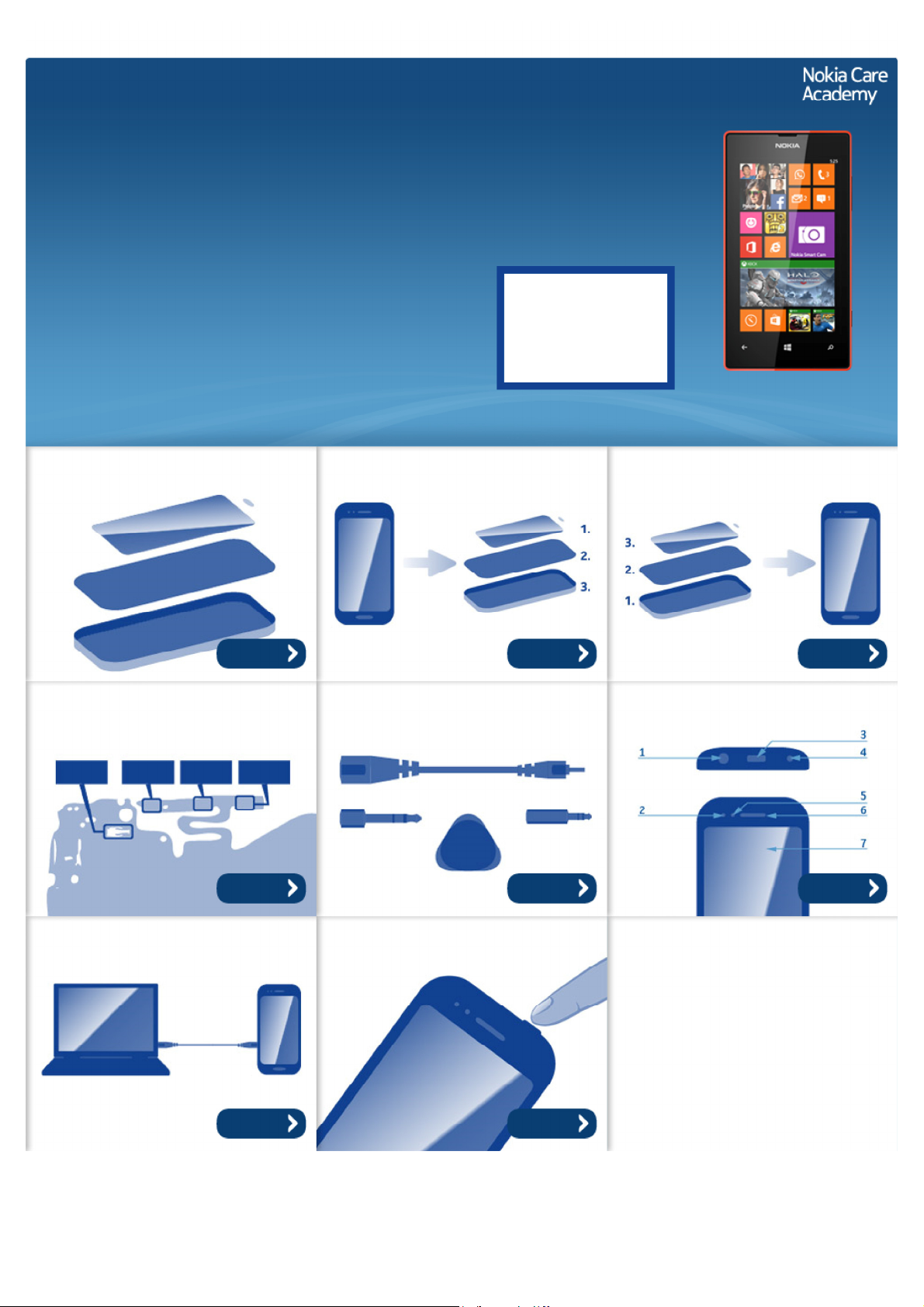
Exploded view Disassembly steps Assembly hints
More More More
Solder components Service devices Product controls and interfaces
More More More
Service concept Phone reset
More More
©2013 Nokia | Nokia Internal Use only | All Rights Reserved.
Service Manual Level 1 and 2
Nokia Lumia 525
RM-998
Version 1.0
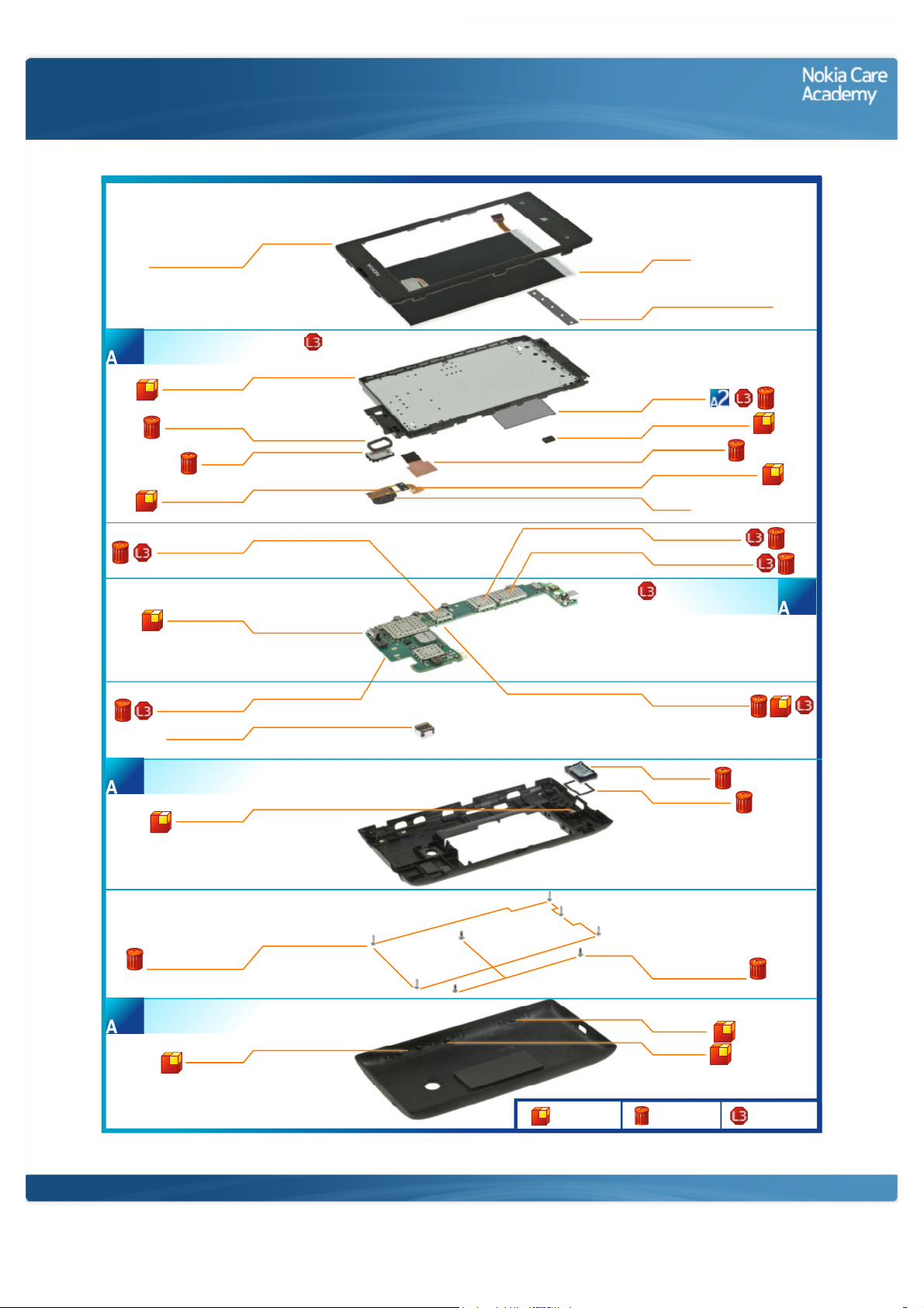
Exploded view
TOUCH WINDOW &
A-COVER ASSEMBLY
DISPLAY SUPPORT ASSEMBLY
(I0003 - I0010)
1
DISPLAY SUPPORT
EARPIECE GASKET
AV JACK ADHESIVE
WCN SHIELDING LID
LIGHT SWAP PWB
PMU SHIELDING LID
CAMERA MODULE
D-COVER ASSEMBLY
(I0022 - I0024)
3
I0001
I0003
I0005
EARPIECE
I0004
I0007
I0019
I0011
I0016
I0015
MAIN ANTENNA
I0024
DISPLAY
I0002
DISPLAY CONDUCTIVE TAPE
I0029
TYPE LABEL
I0012
MICROPHONE GASKET
I0010
HEAT SPREADER
I0009
AV JACK FLEX ADHESIVE
I0008
AV JACK
I0006
RF IC SHIELDING LID
I0018
CELL PA SHIELDING LID
I0021
LIGHT SWAP PACKAGE
EMMC SHIELDING LID
I0017
IHF SPEAKER
I0023
SPEAKER GASKET
I0022
(I0011 - I0012)
2
SIZE 4 M1.4 x 4.5
B-COVER ASSEMBLY
(I0026 - I0028)
4
SCREW TORX+
I0025
VOLUME KEY
I0026
Only available
as assembly
©2013 Nokia | Nokia Internal Use only | All Rights Reserved.
SCREW TORX+
SIZE 4 M1.4 X 3.4
I0013
CAMERA KEY
I0027
POWER KEY
I0028
Not reuseable
after removal
Repair/swap
only in level 3
Service Manual Level 1 and 2
Nokia Lumia 525
RM- 998
Version 1.0
Disassembly steps
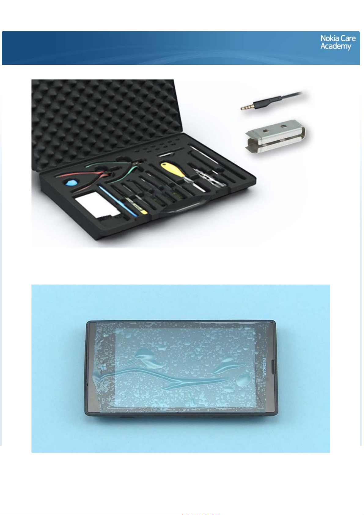
1) For disassembling you need the Nokia Standard toolkit version 2. You will also need the camera
removal tool SS-305 and an AV plug.
2) Protect the TOUCH WINDOW with protective film.
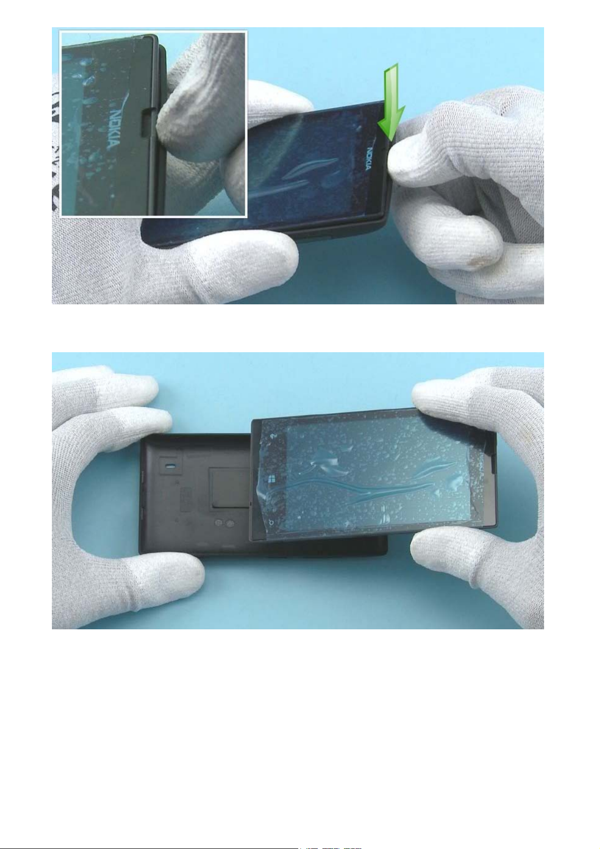
3) Release the BACK COVER by pushing from the top.
4) Remove the BACK COVER.
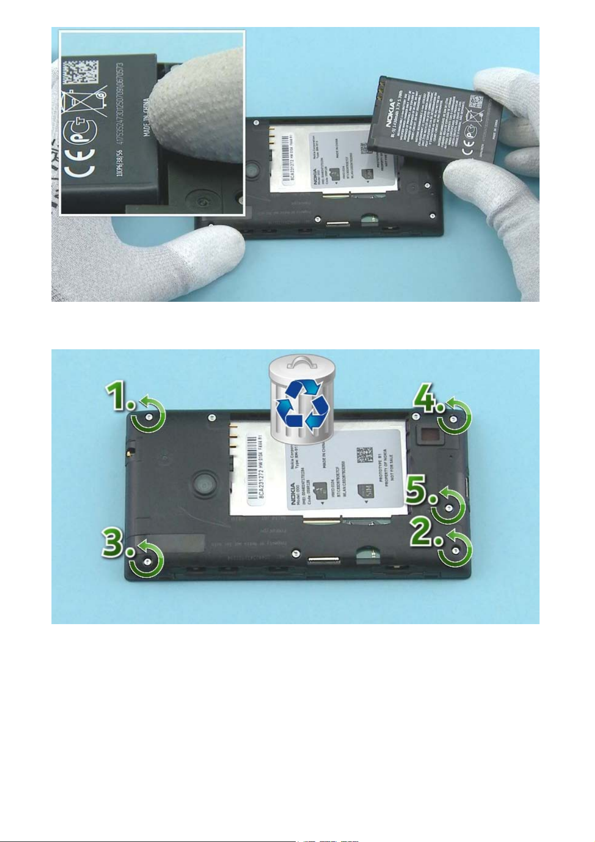
5) Lift up the BATTERY from the bottom and remove it.
6) Unscrew the five Torx+ size 4 screws in the order shown. Do not use them again. Discard them.
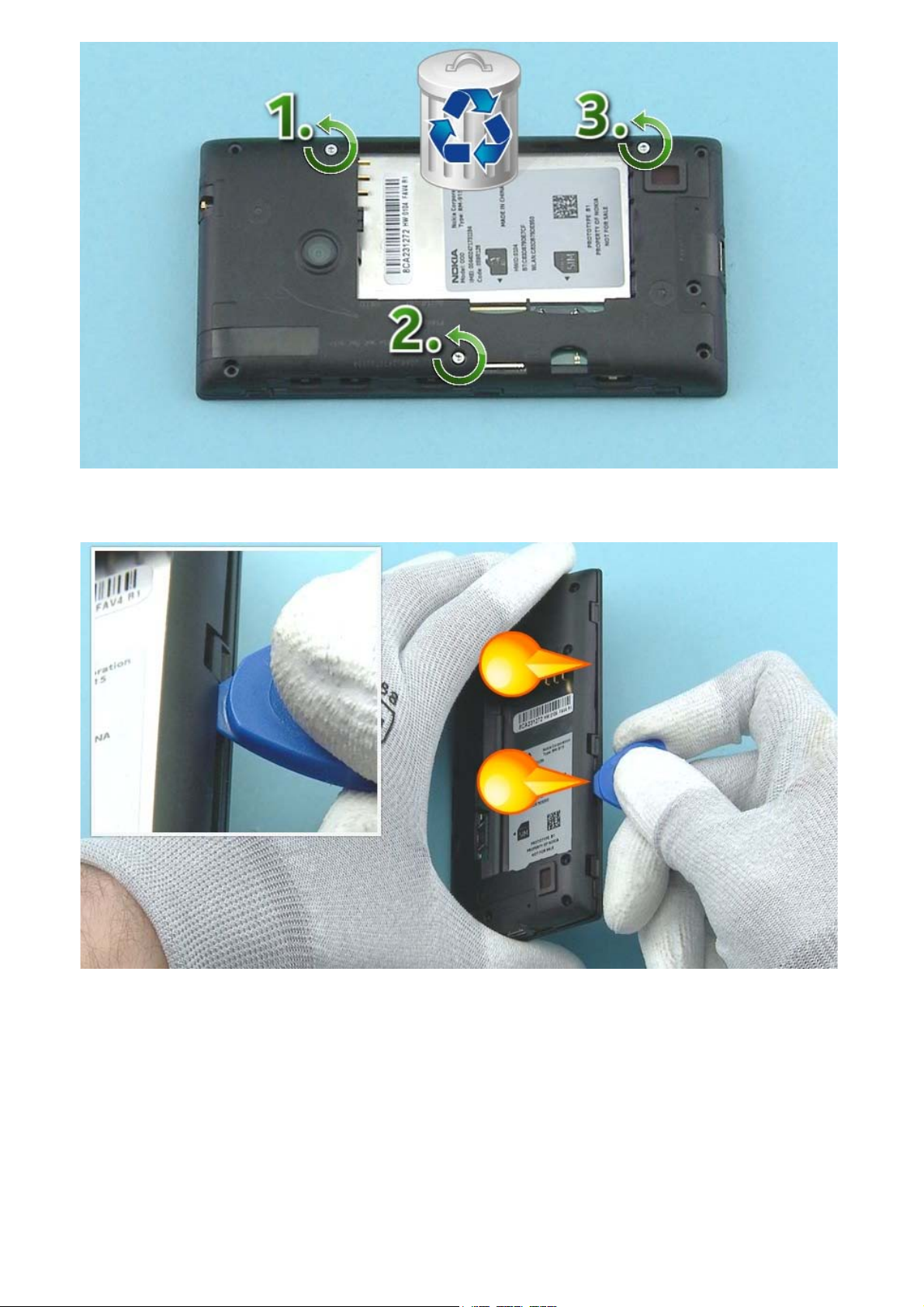
7) Unscrew the three Torx+ size 4 screws in the order shown. Do not use them again. Discard them.
8) Release the two clips on the left side of the D-COVER with the SRT-6, starting from the bottom.
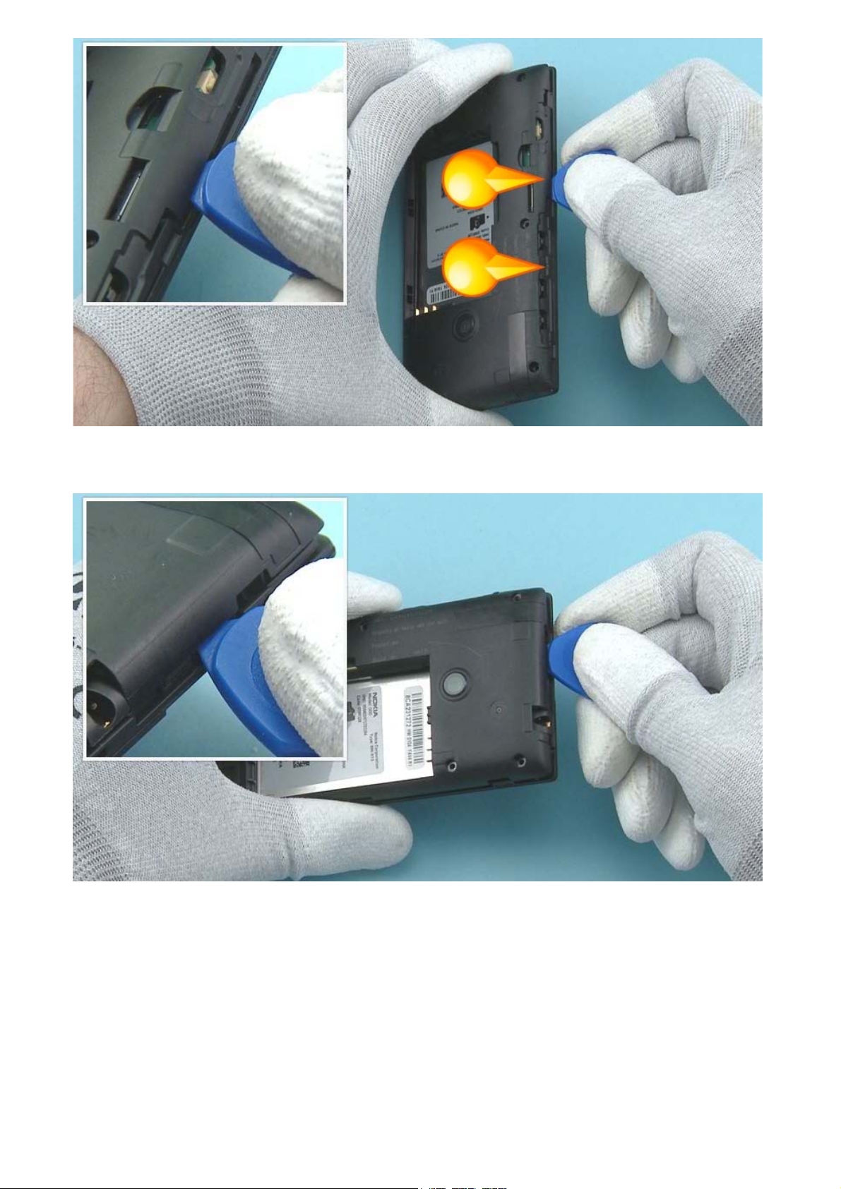
9) Then release the two clips on the right side of the D-COVER, starting from the bottom.
10) Release also the top side of the D-COVER from the shown place.
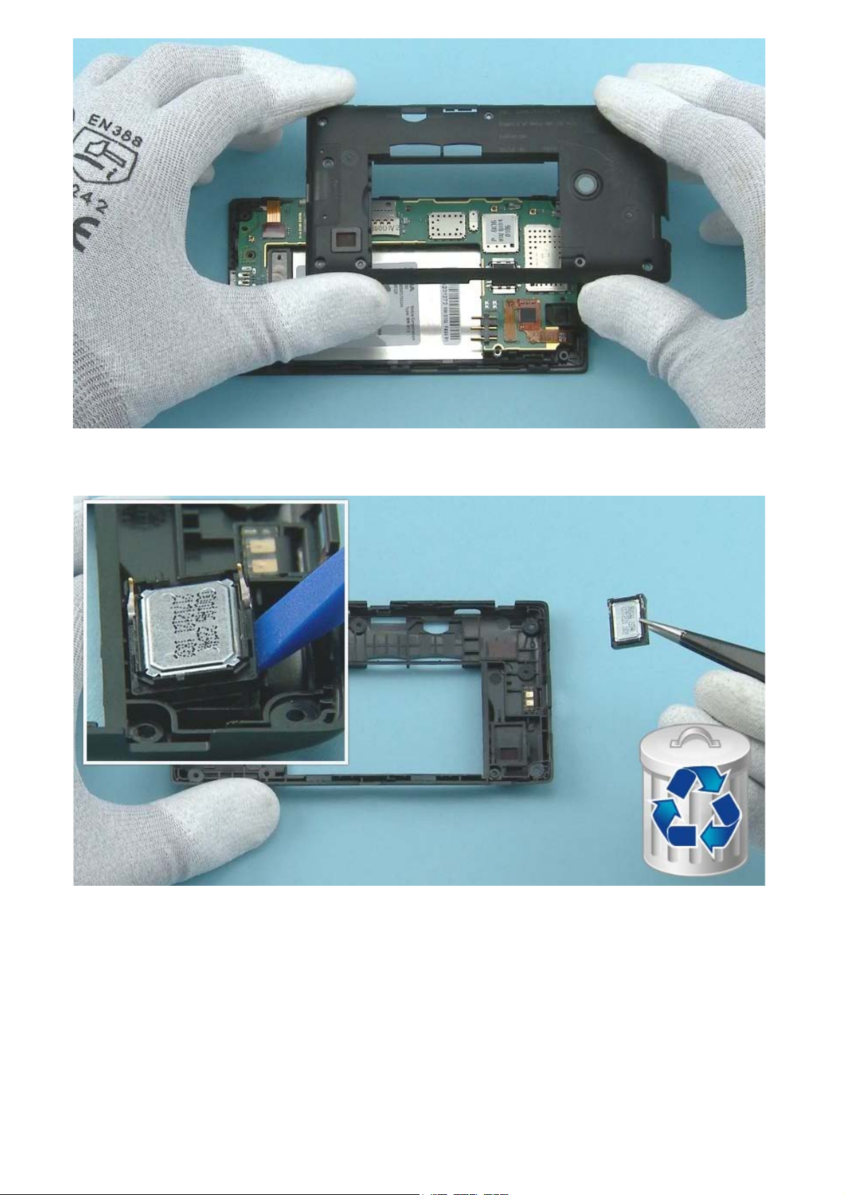
11) Lift up and remove the D-COVER.
12) Release the IHF SPEAKER with the SS-93 and remove it with tweezers. Do not use it again. Discard it.
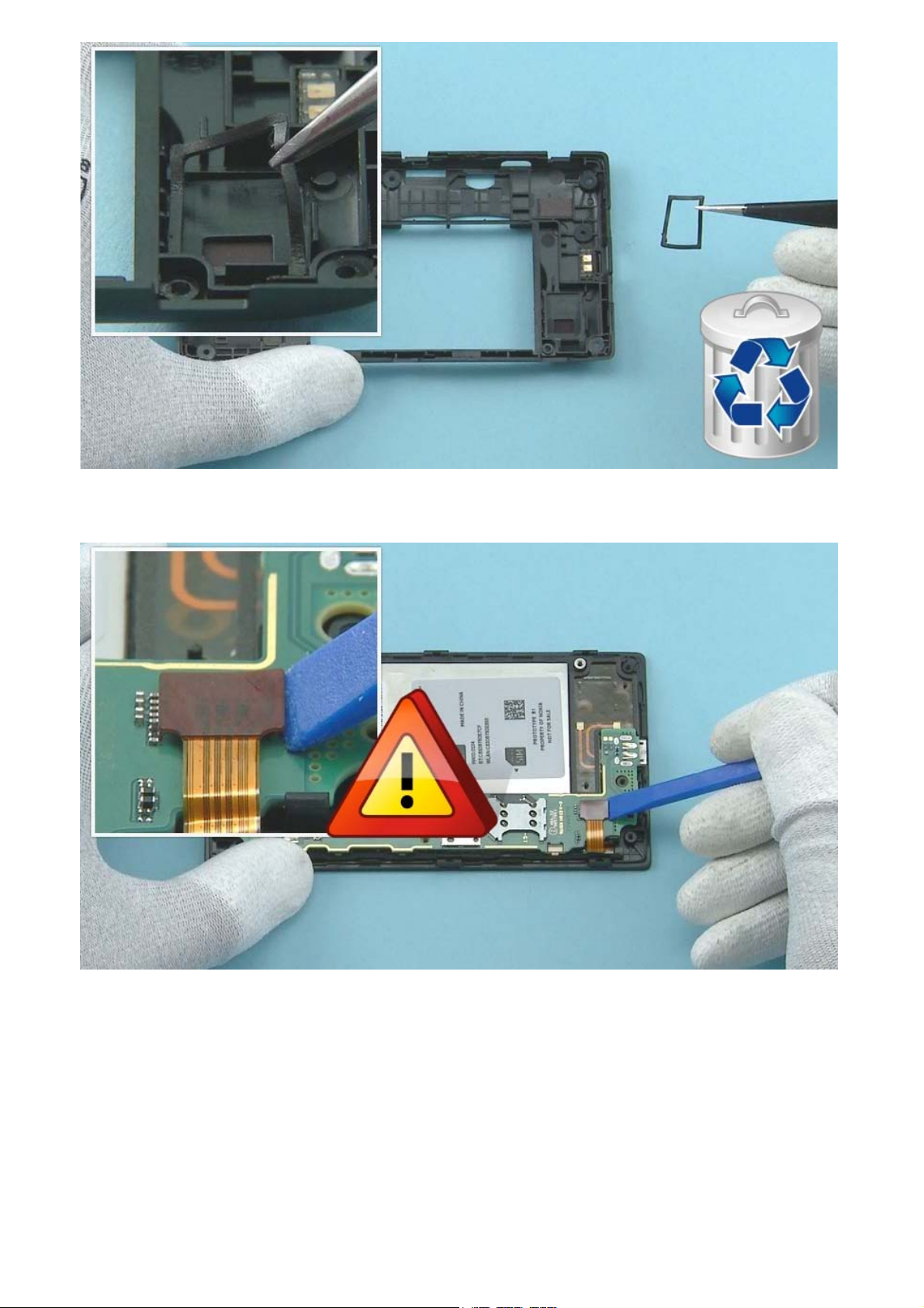
13) Remove the SPEAKER GASKET with tweezers. Do not use it again. Disard it.
14) Open the DISPLAY connector with the SS-93. Be careful not to damage the connector or any
components nearby.
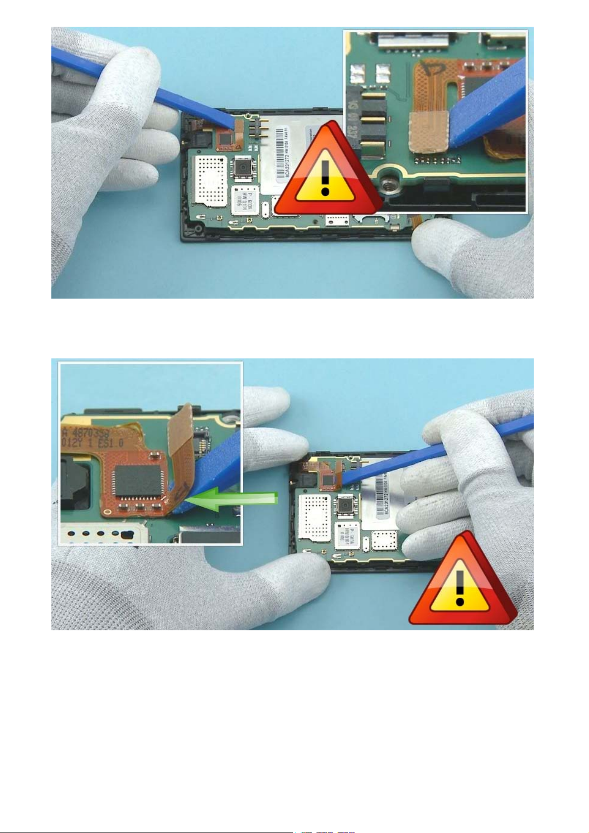
15) Open the TOUCH WINDOW connector with the SS-93. Be careful not to damage the connector or any
components nearby.
16) Release the TOUCH WINDOW connector flex from the ENGINE BOARD by carefully pushing it with the
SS-93. Be careful not to damage the flex.
 Loading...