

Page 1
Page 2

RM-84/99
Nokia Customer Care Disassembly/Reassembly Instructions
(This page left intentionally blank.)
Page 1–2 Company Confidential Issue 1
Copyright ©2005 Nokia. All Rights Reserved.
Page 3

RM-84/99
Disassembly/Reassembly Instructions Nokia Customer Care
Table of Contents
Disassembly / reassembly............................................................................................................................................................1–5
Issue 1 Company Confidential Page 1–3
Copyright ©2005 Nokia. All Rights Reserved.
Page 4

RM-84/99
Nokia Customer Care Disassembly/Reassembly Instructions
(This page left intentionally blank.)
Page 1–4 Company Confidential Issue 1
Copyright ©2005 Nokia. All Rights Reserved.
Page 5
RM-84/99
Disassembly/Reassembly Instructions Nokia Customer Care
Disassembly / reassembly
Before you begin
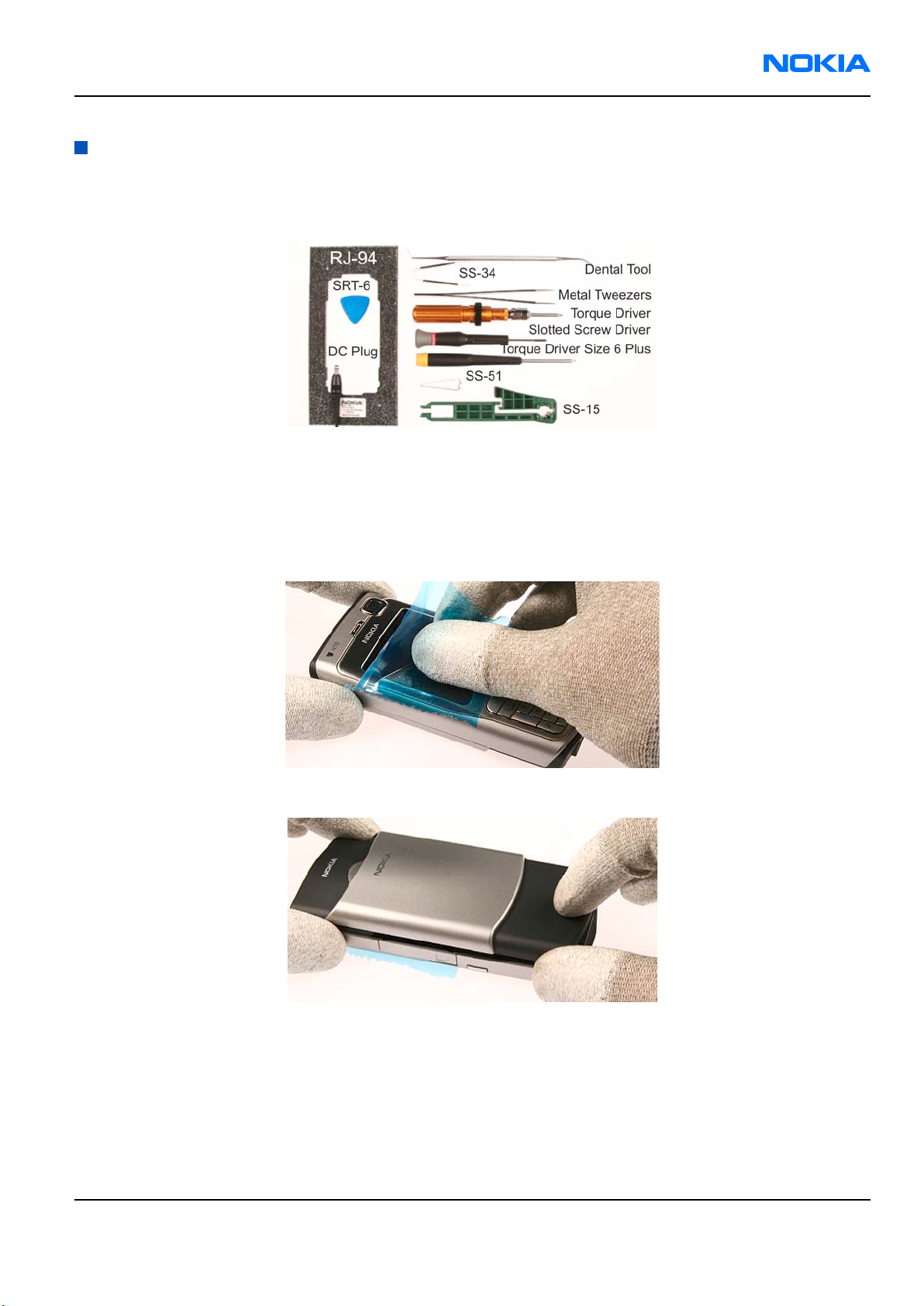
Required tools for RM-84 disassembly:
Note: Reassembly takes places in the reverse order.
Note the reassembly-specific instructions in steps 12., 13., 18., 20., 27., 31., and 33..
Steps
1. Always protect the window with a plastic film.
2. Remove the C-Cover.
Issue 1 Company Confidential Page 1–5
Copyright ©2005 Nokia. All Rights Reserved.
Page 6

RM-84/99
Nokia Customer Care Disassembly/Reassembly Instructions
3. Place SRT-6 between the A-Cover and Chassis; release the 4 plastic clips beginning from the bottom side
as shown.
4. Remove the Keymat.
5. Protect the LCD with a plastic film.
6. Protect the inner side window of the A-Cover with a film.
Page 1–6 Company Confidential Issue 1
Copyright ©2005 Nokia. All Rights Reserved.
Page 7

RM-84/99
Disassembly/Reassembly Instructions Nokia Customer Care
7. Remove the MMC door from the A-Cover.
8. Insert SRT-6 between the Antenna Cover and Chassis, and open the Antenna Cover clips.
Note: Additional force may be required to open the clips.
9. Use the tweezers to remove the Power Key.
10. Protect the Camera Bezel with a plastic film before turning the unit.
Issue 1 Company Confidential Page 1–7
Copyright ©2005 Nokia. All Rights Reserved.
Page 8

RM-84/99
Nokia Customer Care Disassembly/Reassembly Instructions
11. Remove the Camera Gasket.
12. Unlock and remove the VGA Camera with the SS-51 camera removal tool.
Note: When reassembling, note the correct position of the Camera when fitting it back into its
compartment.
13. Unscrew the 6 Torx size 6 plus screws in the order shown.
Note: When reassembling, use the reverse order and the torque of 25 Ncm.
Page 1–8 Company Confidential Issue 1
Copyright ©2005 Nokia. All Rights Reserved.
Page 9

RM-84/99
Disassembly/Reassembly Instructions Nokia Customer Care
14. Lift the UI Frame from the Chassis. Be careful not to damage the flex foil of the LCD, which is still connected.
15. Open the flex connector with the SS-34 flex connector opening tool.
Note: Be careful not to damage the surrounding components when using the tool.
After you have opened the flex connector, you can remove the UI Frame.
16. To open each clip of the LCD from the UI Frame, carefully move the UI Frame sideward while pulling the
LCD forward.
17. Use the dental tool to remove the Earpiece.
Issue 1 Company Confidential Page 1–9
Copyright ©2005 Nokia. All Rights Reserved.
Page 10

RM-84/99
Nokia Customer Care Disassembly/Reassembly Instructions
18. Use the tweezers to remove the Earpiece Gasket from its compartment.
Note: When reassembling, always use a new gasket.
19. Use SRT-6 to unlatch the BB shield.
20. To remove the BB shield from the UI Frame, hold the frame in your left hand and push down the BB
Shield with SRT-6.
Note: When reassembling, always use a new BB Shield.
21. To unlock the UI PWB from the UI Frame, carefully pull the PWB upwards.
Page 1–10 Company Confidential Issue 1
Copyright ©2005 Nokia. All Rights Reserved.
Page 11

RM-84/99
Disassembly/Reassembly Instructions Nokia Customer Care
22. Remove the UI PWB.
23. Remove the Engine Module and place it onto the RJ-94 jig.
24. Use the tweezers to remove the Vibra Motor.
25. Use the tweezers to pull out the Microphone.
Issue 1 Company Confidential Page 1–11
Copyright ©2005 Nokia. All Rights Reserved.
Page 12

RM-84/99
Nokia Customer Care Disassembly/Reassembly Instructions
26. Use the DC plug to remove the DC Jack.
27. Use the tweezers to lift out the IHF speaker.
Note: When reassembling, note the guide pin.
28. Unlock the 5 plastic clips of the Antenna in the places shown.
29. Carefully separate the Antenna from the UI Frame.
Page 1–12 Company Confidential Issue 1
Copyright ©2005 Nokia. All Rights Reserved.
Page 13

RM-84/99
Disassembly/Reassembly Instructions Nokia Customer Care
30. Use SRT-6 to lift out the Camera Rear Bezel Assy.
31. Use SRT-6 to completely remove the residues of the Camera Rear Bezel Assy adhesive.
Note: When reassembling, always use new adhesive.
32. To prevent mechanical stress to the PWB, place the Engine Module onto RJ-94, and use SS-15 to remove
the Camera module.
33. Attention: The following steps are for reassembly only!
• Use the assembly side of SS-15 to fit the Camera module back into its compartment.
• When reassembling, note the correct position of the Camera module.
Issue 1 Company Confidential Page 1–13
Copyright ©2005 Nokia. All Rights Reserved.
Page 14

RM-84/99
Nokia Customer Care Disassembly/Reassembly Instructions
Page 1–14 Company Confidential Issue 1
Copyright ©2005 Nokia. All Rights Reserved.
 Loading...