

Nokia Asha 500 Dual SIM RM 934, Asha 500 RM-973, Asha 500, RM 934, RM-972 Service Manual
...Page 1
Check the repair
policy before
performing any
mechanical repair
on Service Level
1&2!
Service Manual for L1 andL
2
Nokia Asha 500 Dual SIM
RM-934, RM-97
2
Nokia Asha 500
RM-973
Key features
z
2.8" QVGA Display
z
Capacitive touch screen and back key
z
2 MP Camera
z
Wi-Fi support
z
Micro SD card support up to 32 GB
Version 1.0
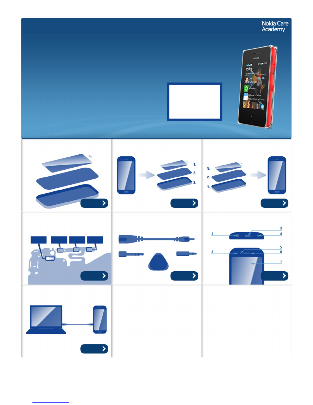
Exploded view Disassembly steps Assembly hints
Solder components Service devices Product controls and interfaces
Service concept
©2013 Nokia | Nokia Internal Use only | All Rights Reserved.
More More More
More More More
More
Page 2
Service Manual Level 1 and 2
Nokia Asha 500 Dual SIM, Nokia Asha 500
RM-934 RM-972 (Dual SIM), RM-973 (Single SIM)
Version 1.0
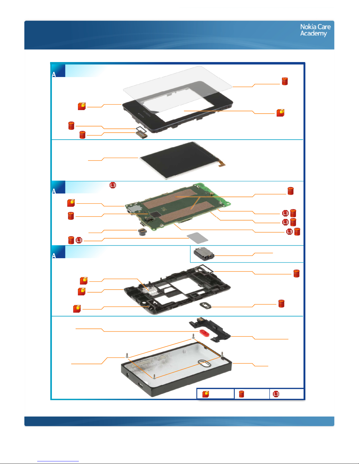
Exploded view
EARPIECE GASKET
I0004
RELEASE BUTTON
I0022
A-COVER
I0001
EARPIECE
I0003
DISPLAY
I0014
LIGHT SWAP PWB
I0008
CAMERA
I0006
D-COVER
I0020
BT ANTENNA
I0018
SIM LID
I0019
TYPE LABEL
I0013
TOUCH IC GASKET
I0007
TOUCH PANEL
I0002
DISPLAY CONDUCTIVE
ADHESIVE
I0012
TOUCH WINDOW
PROTECTIVE TAPE
I0005
IHF SPEAKER
I0015
SPEAKER MESH
I0017
SPEAKER BOTTOM GASKET
I0016
GSM ANTENNA MODULE
I0021
B-COVER
I0024
BB SHIELDING LID
I0009
RF SHIELDING LID
I0010
WLAN SHIELDING LID
I0011
SCREW TORX+ SIZE 6
M1.6 x 4.3
I0023
LIGHT SWAP PACKAGE
(I0006 - I0013)
2
D-COVER ASSEMBLY
(I0016 - I0020)
3
A-COVER ASSEMBLY
(I0001 - I0005)
1
Only available
as assembly
Not reuseable
after removal
Repair/swap
only in level 3
©2013 Nokia | Nokia Internal Use only | All Rights Reserved.
Page 3
Service Manual Level 1 and 2
Nokia Asha 500 Dual SIM, Nokia Asha 500
RM- 934 RM -972 (Dual SIM), RM -973 (Single SIM)
Version 1.0
Disassembly steps
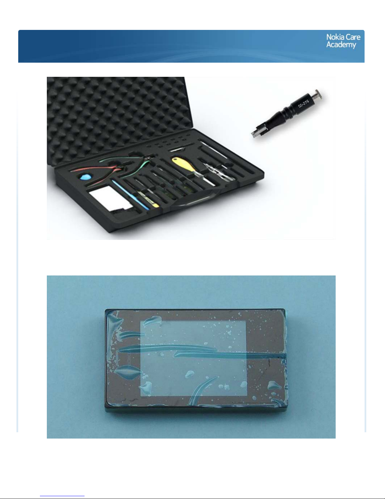
1) For disassembling you need the Nokia Standard toolkit version 2. You will also need the camera
removal tool SS-276.
2) Protect the TOUCH PANEL with protective film.
Page 4
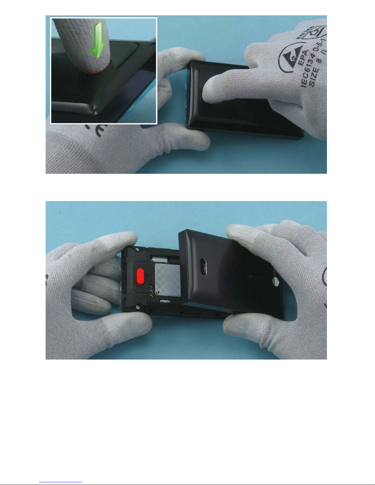
3) Push from the RELEASE BUTTON to release the B-COVER.
4) Remove the B-COVER.
Page 5
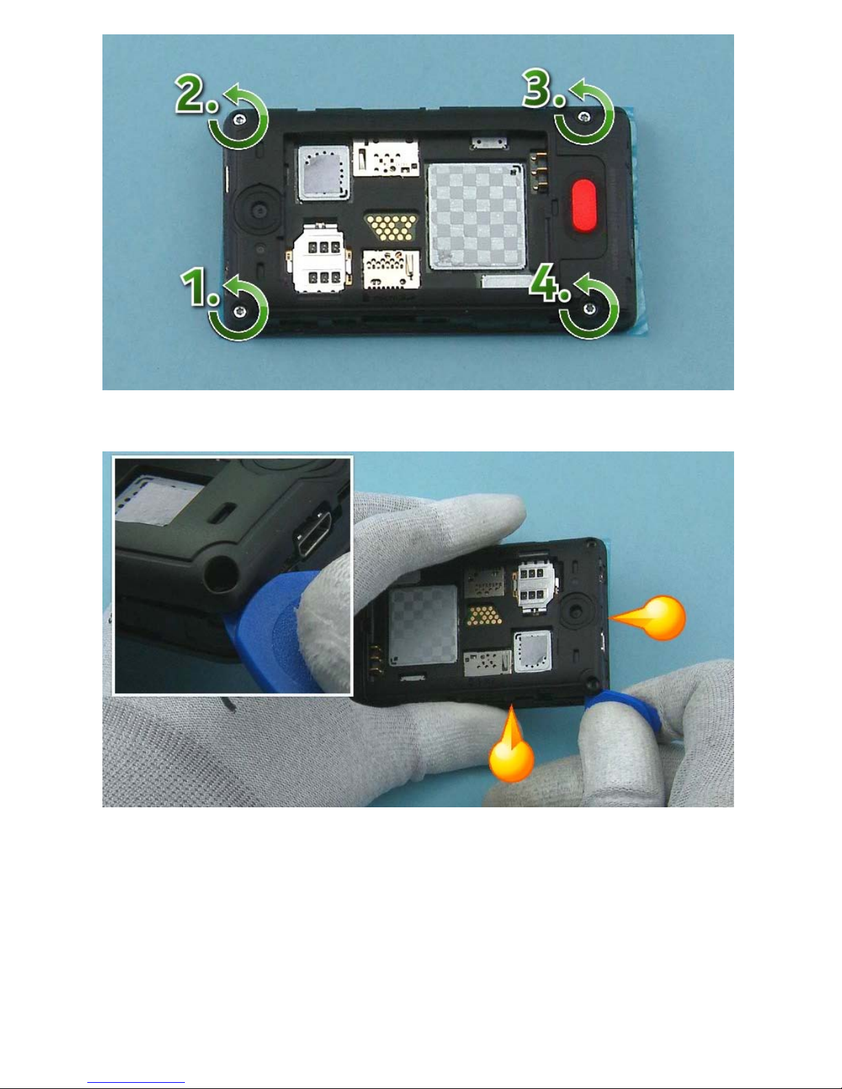
5) Unscrew the four Torx+ size 6 screws in the order shown.
6) Start releasing the D-COVER from the top left corner with the SRT-6 to detach the two shown clips.
Page 6
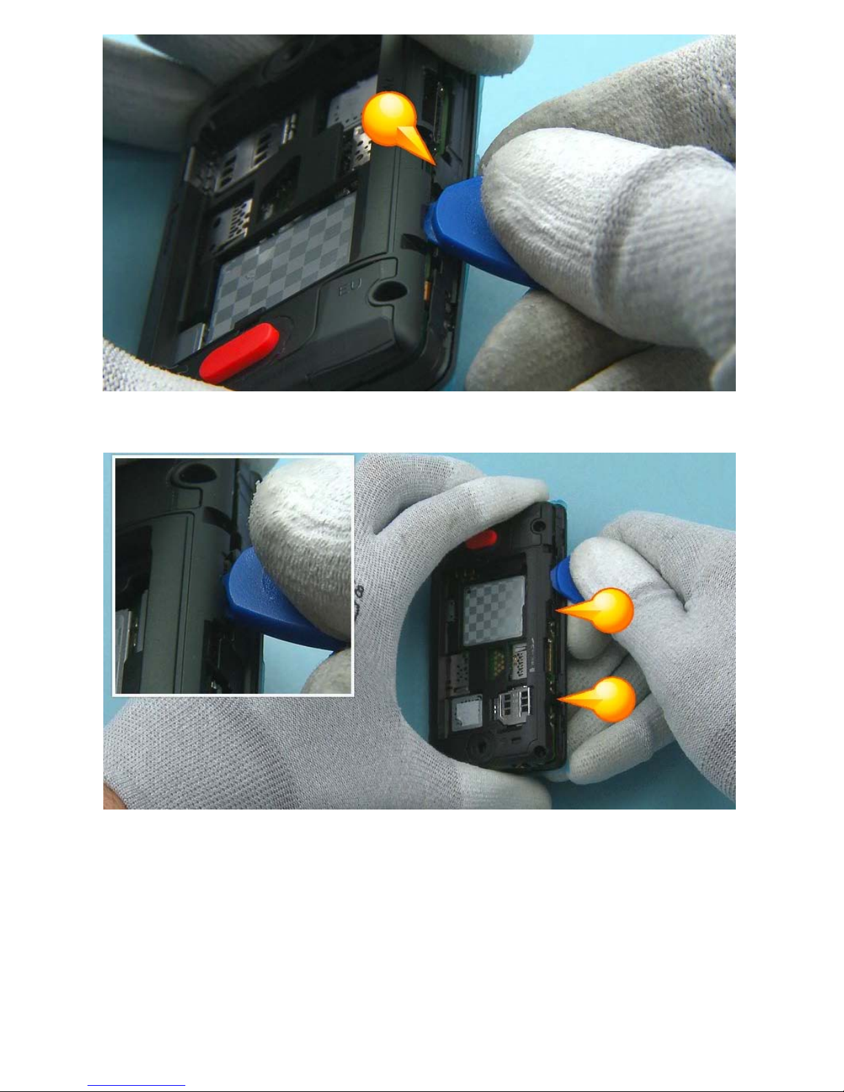
7) Then release the other clip on the left side of the device.
8) Then release the two clips on the right side of the device
Page 7
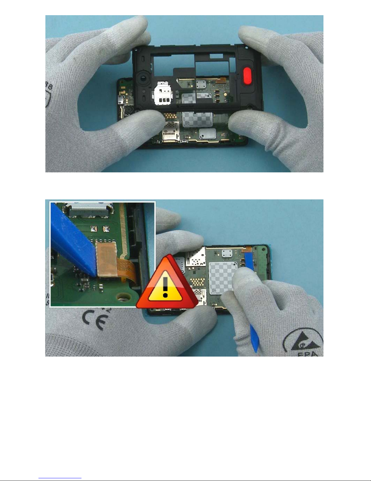
9) Remove the D-COVER.
10) Open the DISPLAY connector. Be careful not to damage the connector or any components nearby.
Page 8

11) To remove the ENGINE BOARD, first release the shown clip with the SRT-6.
12) Then release the other shown clip with the SRT-6.
Page 9

13) Remove the ENGINE BOARD.
14) Protect the DISPLAY with protective film.
Page 10

15) Release the DISPLAY by carefully sliding the SS-93 under it to detach the adhesive.
16) Remove the DISPLAY.
Page 11

17) Release one corner of the TOUCH IC GASKET with the dental tool and remove it with tweezers. Be
careful not to injure yourself or damage the ENGINE BOARD with the sharp end of the dental tool. Do not
use the TOUCH IC GASKET again. Disard it.
18) Peel off the two DISPLAY CONDUCTIVE ADHESIVES with the SS-93. Do not use them again. Discard
them.
Page 12

19) Use the SS-276 to remove the CAMERA. Push the SS-276 to the CAMERA socket and hold down the
button on top of the SS-276.
20) Pull up the CAMERA.
Page 13

21) Use the SS-93 to release the IHF SPEAKER. Remove the IHF SPEAKER with tweezers.
22) Remove and discard the SPEAKER BOTTOM GASKET with the dental tool.
Page 14

23) Use the SS-93 to release the hook holding the ANTENNA MODULE.
24) Push up to release the ANTENNA MODULE as shown with the SRT-6. Remove the ANTENNA MODULE.
Page 15

25) Release the RELEASE BUTTON with the SRT-6 and remove it.
26) Release one corner of the SPEAKER MESH with the dental tool and peel it off with tweezrs. Do not use
the SPEAKER MESH again. DIscard it.
Page 16

27) Protect the other side of the TOUCH PANEL with protective film.
28) Release the EARPIECE with the dental tool and remove it with weezers. Do not use the EARPIECE
again. Discard it.
Page 17

29) Remove and discard the EARPIECE GASKET.
30) The Nokia Asha 500 disassembly procedure is complete.
-END OF DISASSEMBLY-
©2013 Nokia | Nokia Internal Use only | All Rights Reserved.
Page 18

Service Manual Level 1 and 2
Nokia Asha 500 Dual SIM, Nokia Asha 500
RM- 934 RM -972 (Dual SIM), RM -973 (Single SIM)
Version 1.0
Assembly hints
1) Fasten the four Torx+ size 6 screws in the order shown to the torque of 20 Ncm.
©2013 Nokia | Nokia Internal Use only | All Rights Reserved.
Page 19

Service Manual Level 1 and 2
Nokia Asha 500 Dual SIM, Nokia Asha 500
RM-934 RM-972 (Dual SIM), RM-973 (Single SIM)
Version 1.0
Solder components
J7402S1002S1000
J7400J7401
GSM Ant
gnd spring
Power/Lock
switch
Volume -
switch
Volume +
switch
GSM Ant
spring
GSM Ant
gnd spring
TOP
BOTTOM
©2013 Nokia | Confidential | All Rights Reserved.
Page 20

Service Manual Level 1 and 2
Nokia Asha 500 Dual SIM, Nokia Asha 500
RM-934 RM-972 (Dual SIM), RM-973 (Single SIM)
Version 1.0
Service devices
AC-20 Travel charger BL-4U Battery SS-276 Camera removal tool
Nokia Standard Toolkit (v2)
For more information, refer to the Service
Bulletin (SB-011) on Nokia Online. Supplier or
manufacturer contacts for tool re-order can
be found in “Recommended service
equipment” document on Nokia Online.
©2013 Nokia | Nokia Internal Use only | All Rights Reserved.
Page 21

Service Manual Level 1 and 2
Nokia Asha 500 Dual SIM, Nokia Asha 500
RM-934 RM-972 (Dual SIM), RM-973 (Single SIM)
Version 1.0
Product controls and interfaces
8 — Volume/Zoom up
7 — Camera
6 — Microphone
5 — Back key
4 — Touch screen
3 — Earpiece
2 — 3.5 mm AHJ connector
1 — Micro-USB connector
9 — Volume/Zoom down
10 — Lock/Power key
12 — BT/WLAN Antenna area
14 — Main antenna area
13 — Loudspeaker
11 — Back cover release button
2
4
5
1
3
8
9
10
11
6
14
12
13
7
©2013 Nokia | Nokia Internal Use only | All Rights Reserved.
Page 22

Service Manual Level 1 and 2
Nokia Asha 500 Dual SIM, Nokia Asha 500
RM-934 RM-972 (Dual SIM), RM-973 (Single SIM)
Version 1.0
Service concept
Flashing concept
Transceiver
Service
software
CA-101
Care Dummy Battery
with power supply
via Nokia charger
or product
specific battery
©2013 Nokia | Nokia Internal Use only | All Rights Reserved.
Page 23

Service Manual Level 1 and 2
Nokia Asha 500 Dual SIM, Nokia Asha 500
RM-934 RM-972 (Dual SIM), RM-973 (Single SIM)
Version 1.0
Version histor
y
Version Date Description
1.0 27.11.2013 First published version
©2013 Nokia | Nokia Internal Use only | All Rights Reserved.
 Loading...