

Page 1
Service Manual for L1 and L2
3
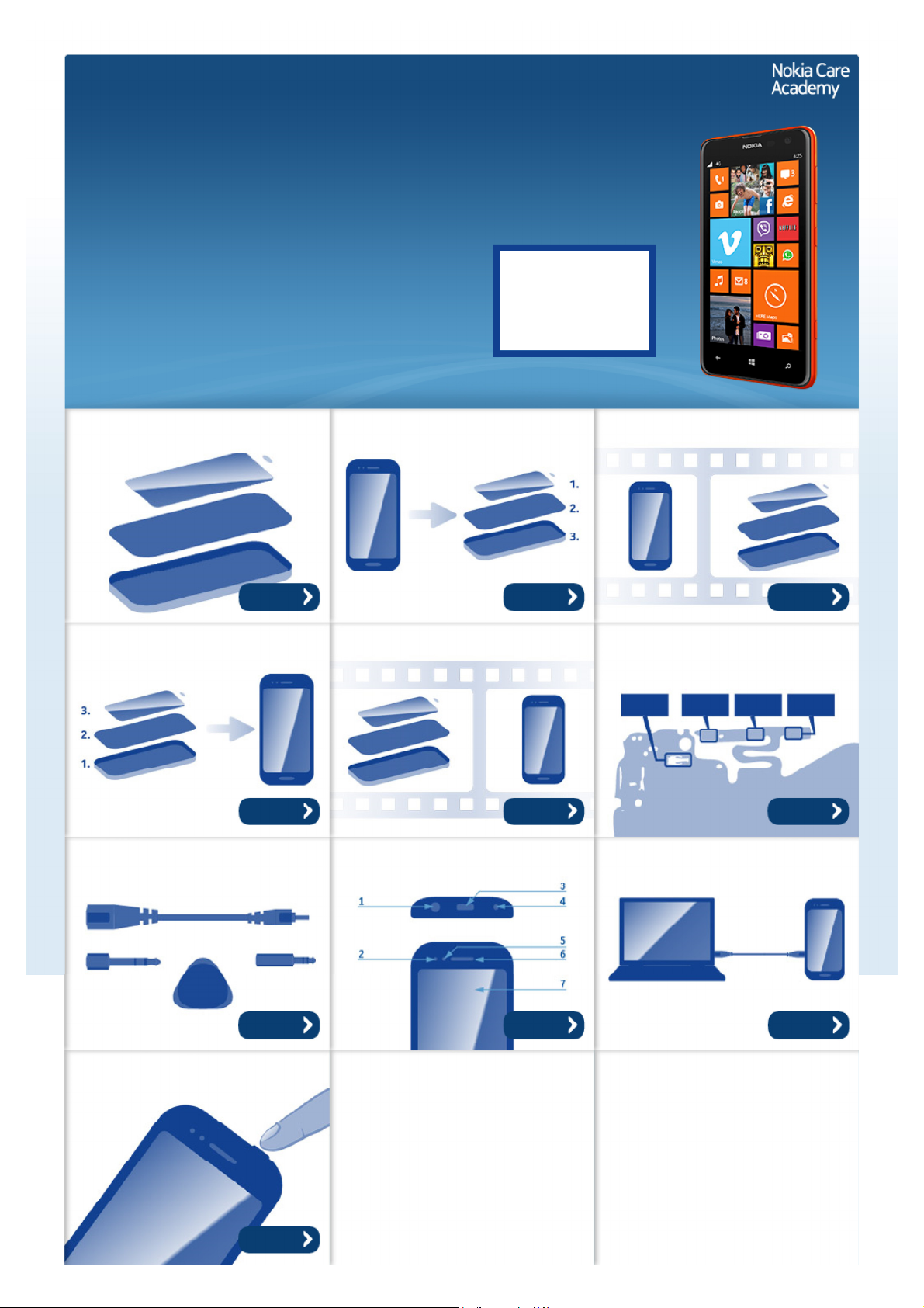
Nokia Lumia 625
RM-941, RM-942, RM-94
Key features
z 4.7" LCD Display
z 2G/3G/4G connectivity
z Bluetooth 4.0 with Bluetooth LE
z 5 Mpix main camera and 0.3 Mpix front camera
Version 1.0
Exploded view Disassembly steps Disassembly video
Check the repair
policy before
performing any
mechanical repair
on Service Level
1&2!
More More More
Assembly steps Assembly video Solder components
More More More
Service devices Product controls and interfaces Service concept
More More More
Phone reset
More
©2013 Nokia | Nokia Internal Use only | All Rights Reserved.
Page 2
Service Manual Level 1 and 2
Nokia Lumia 625
RM-941, RM-942, RM-943
Version 1.0
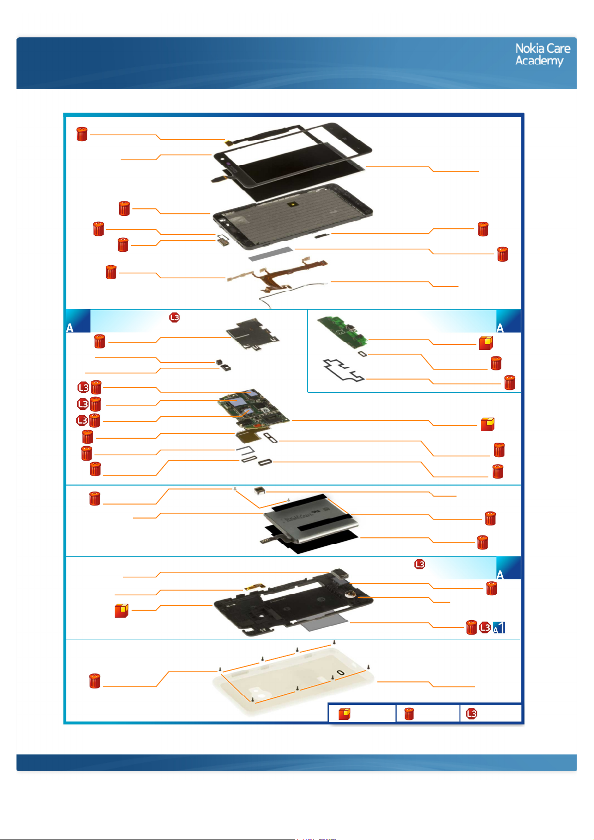
Exploded view
DISPLAY CONNECTOR FILM
TOUCH PANEL
EARPIECE ADHESIVE
SIDE KEY FLEX
LIGHT SWAP PACKAGE
(I0010 - I0022)
1
TOP SHIELDING LID
FRONT CAMERA RUBBER
PROXIMITY SENSOR RUBBER
THERMAL PAD U2700
THERMAL PAD U500
THERMAL PAD U1100
BOTTOM SHIELDING LID
AV CONNECTOR SPONGE
TOUCH PANEL
CONNECTOR RUBBER
SCREW TORX+ SIZE 5
I0003
I0001
A-COVER
I0005
I0007
EARPIECE
I0006
I0008
I0012
I0018
I0017
I0021
I0019
I0020
I0011
I0013
I0016
M2.5 x 2.8
I0024
BATTERY
I0026
DISPLAY MODULE
I0002
DISPLAY MYLAR
I0038
DISPLAY FLEX ADHESIVE
I0004
RF CABLE
I0009
SUB BOARD ASSEMBLY
(I0033 - I0035)
SUB BOARD PWB
I0033
SIDE KEY SUB BOARD
CONNECTOR RUBBER
I0034
SPEAKER SEALING SPONGE
I0035
LIGHT SWAP PWB
I0010
DISPLAY AND SIDE KEY
CONNECTOR RUBBER
I0015
BATTERY CONNECTOR
RUBBER
I0014
CAMERA
I0023
BATTERY ADHESIVE
I0025
BATTERY MYLAR
I0027
3
IHF SPEAKER
I0029
I0032
D-COVER
I0028
SCREW TORX+ SIZE 5
M2.5 x 3.6
I0036
Only available
as assembly
©2013 Nokia | Nokia Internal Use only | All Rights Reserved.
D-COVER ASSEMBLY
(I0028 - I0032)
SPEAKER ADHESIVE
I0030LED FLASH FLEX
VIBRA
I0031
TYPE LABEL
I0022
BATTERY COVER
I0037
Not reuseable
after removal
2
Repair/swap
only in level 3
Page 3
Service Manual Level 1 and 2
Nokia Lumia 625
RM- 941, RM-942, RM-943
Version 1.0
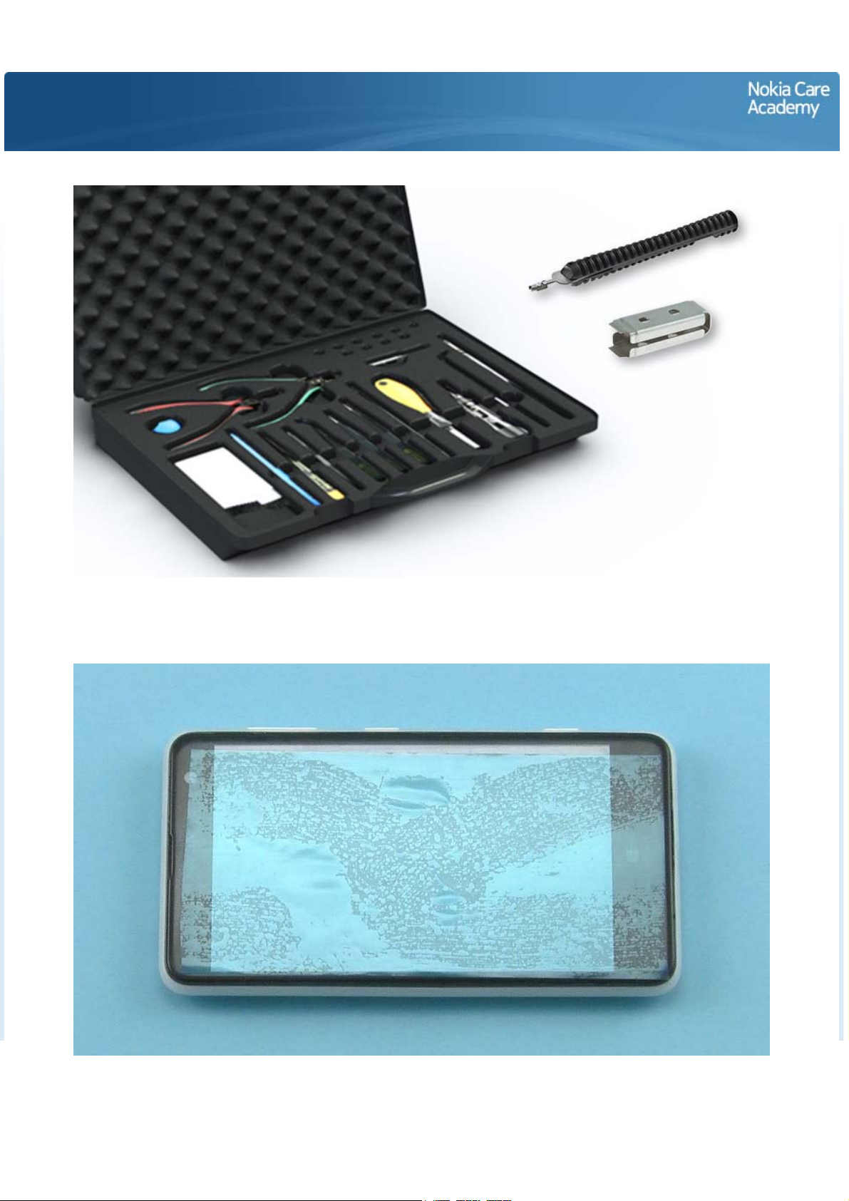
Disassembly steps
1) For disassembling you need the Nokia Standard Tool kit version 2. You will also need the RF connector
disassembly/assembly tool SS-231 or the SS-298 and the camera removal tool SS-305.
2) Protect the TOUCH PANEL with protective film.
Page 4
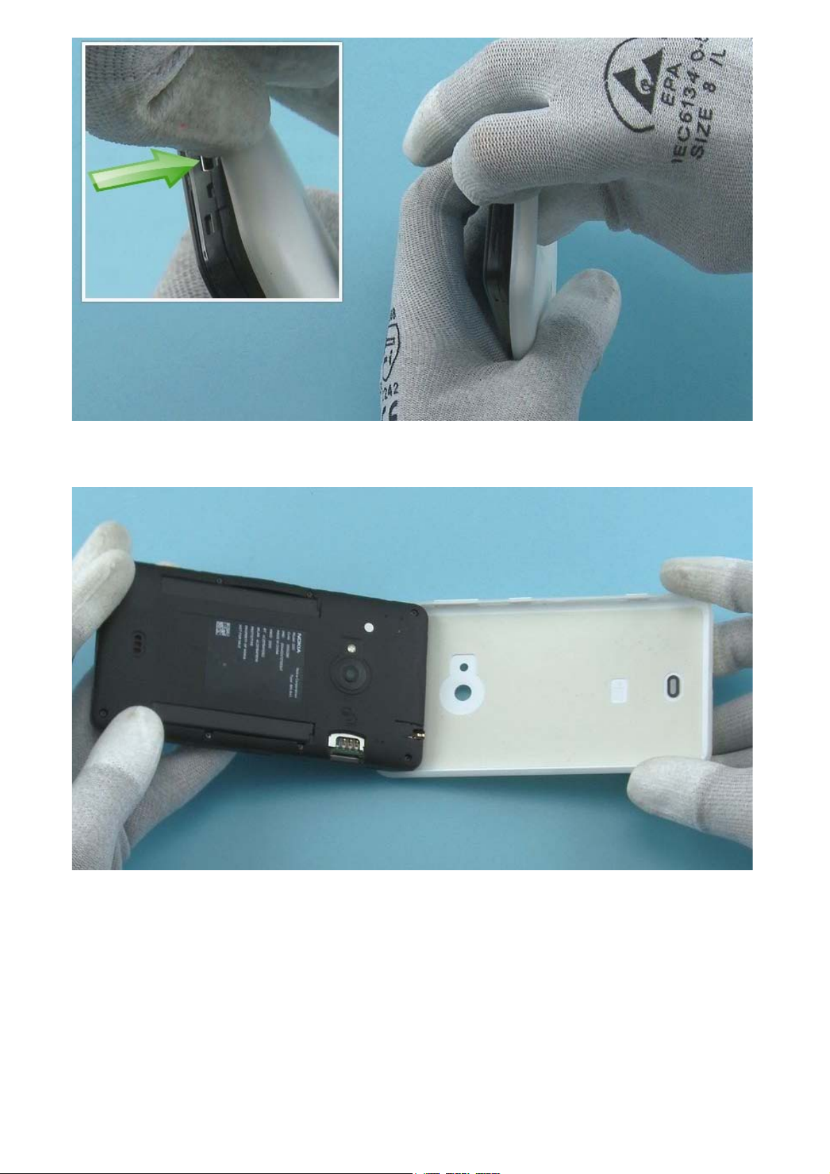
3) Release the BATTERY COVER from the bottom end by pushing from the USB connector hole.
4) Remove the BATTERY COVER.
Page 5
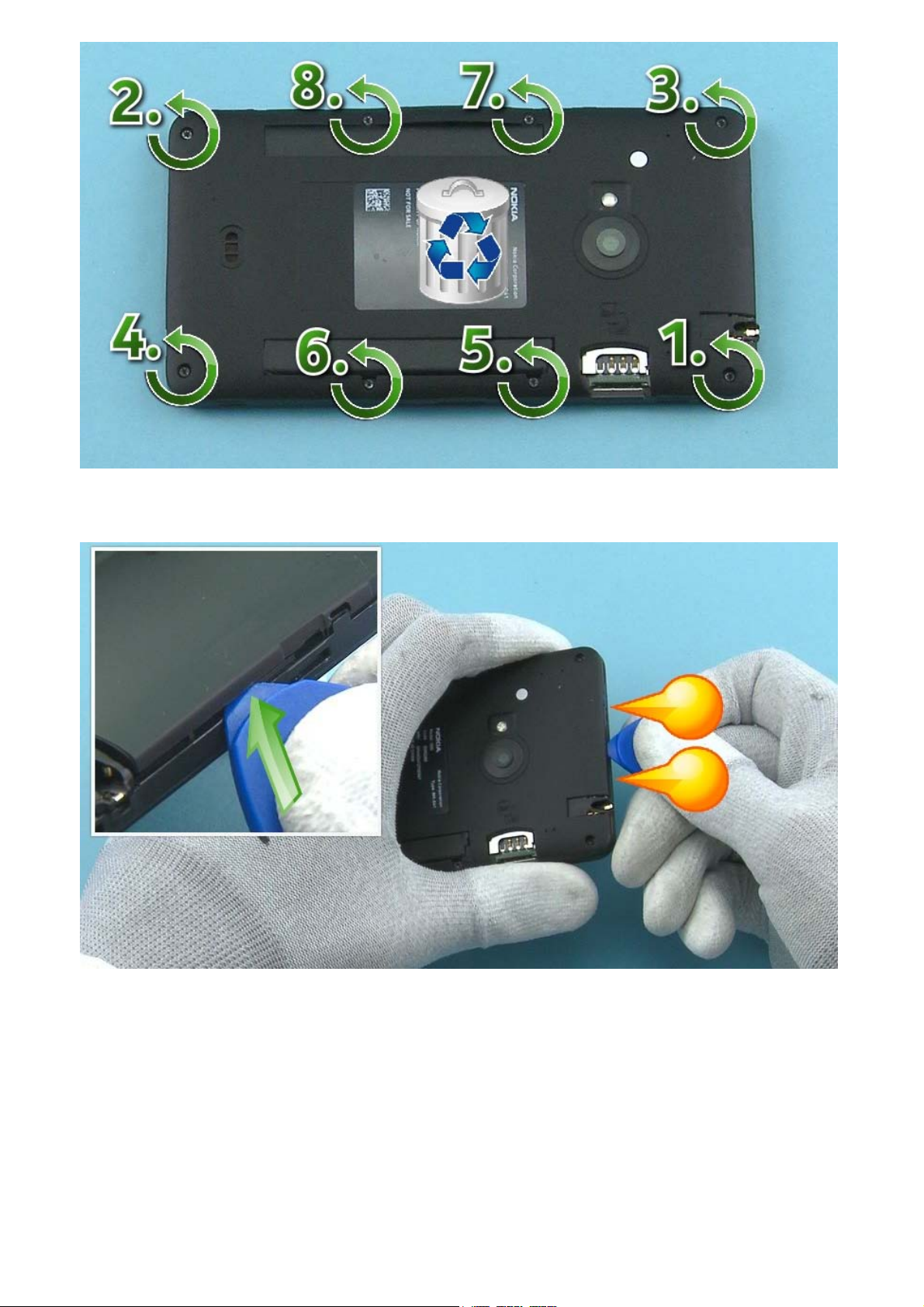
5) Unscrew the eight Torx+ size 5 screws in the order shown. Do not use the screws again. Discard them.
6) To remove the D-COVER, first release the two shown clips on the top of the device. Use the SRT-6 to
push up the D-COVER from the shown place.
Page 6
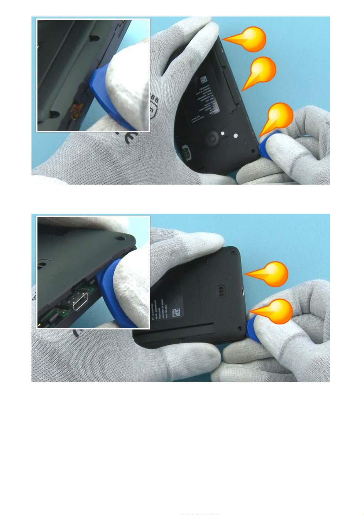
7) Then release the three shown clips from the right side of the device with the SRT-6.
8) Then release the two shown clips from the bottom of the device.
Page 7
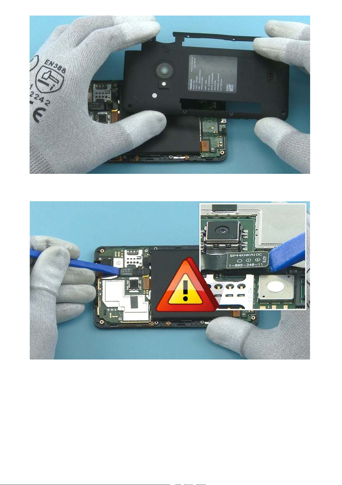
9) Lift up and remove the D-COVER.
10) Open the BATTERY connector with the SS-93. Be careful not to damage the connector or any
components nearby.
Page 8
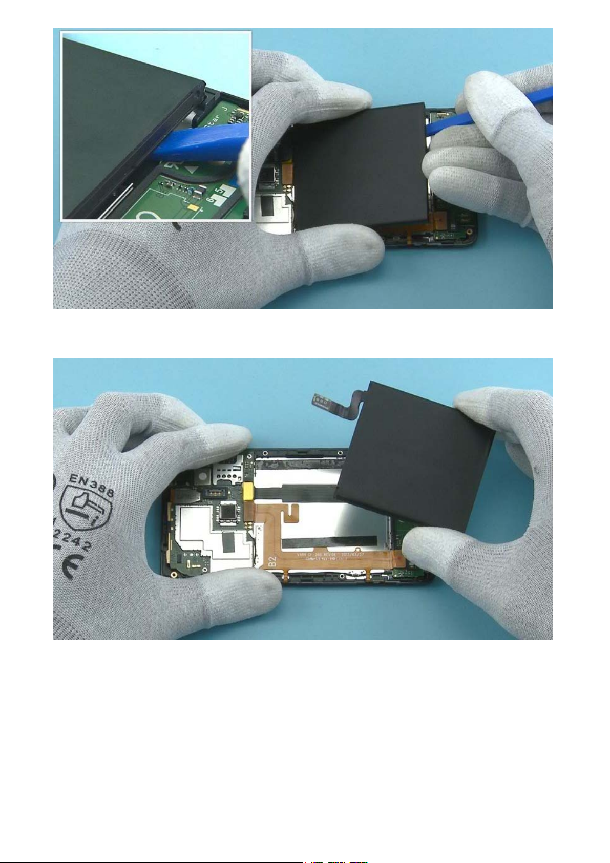
11) Release the adhesive holding the BATTERY from the bottom with the SS-93.
12) Remove the BATTERY.
Page 9
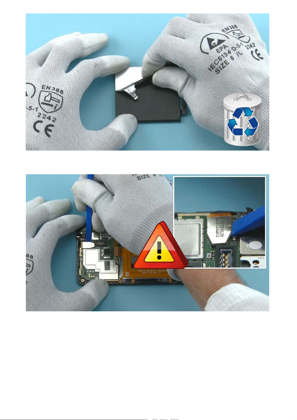
13) Peel off the BATTERY MYLAR. Do not use it again. Discard it.
14) Open the TOUCH PANEL connector with the SS-93. Be careful not to damage the connector or any
components nearby.
Page 10
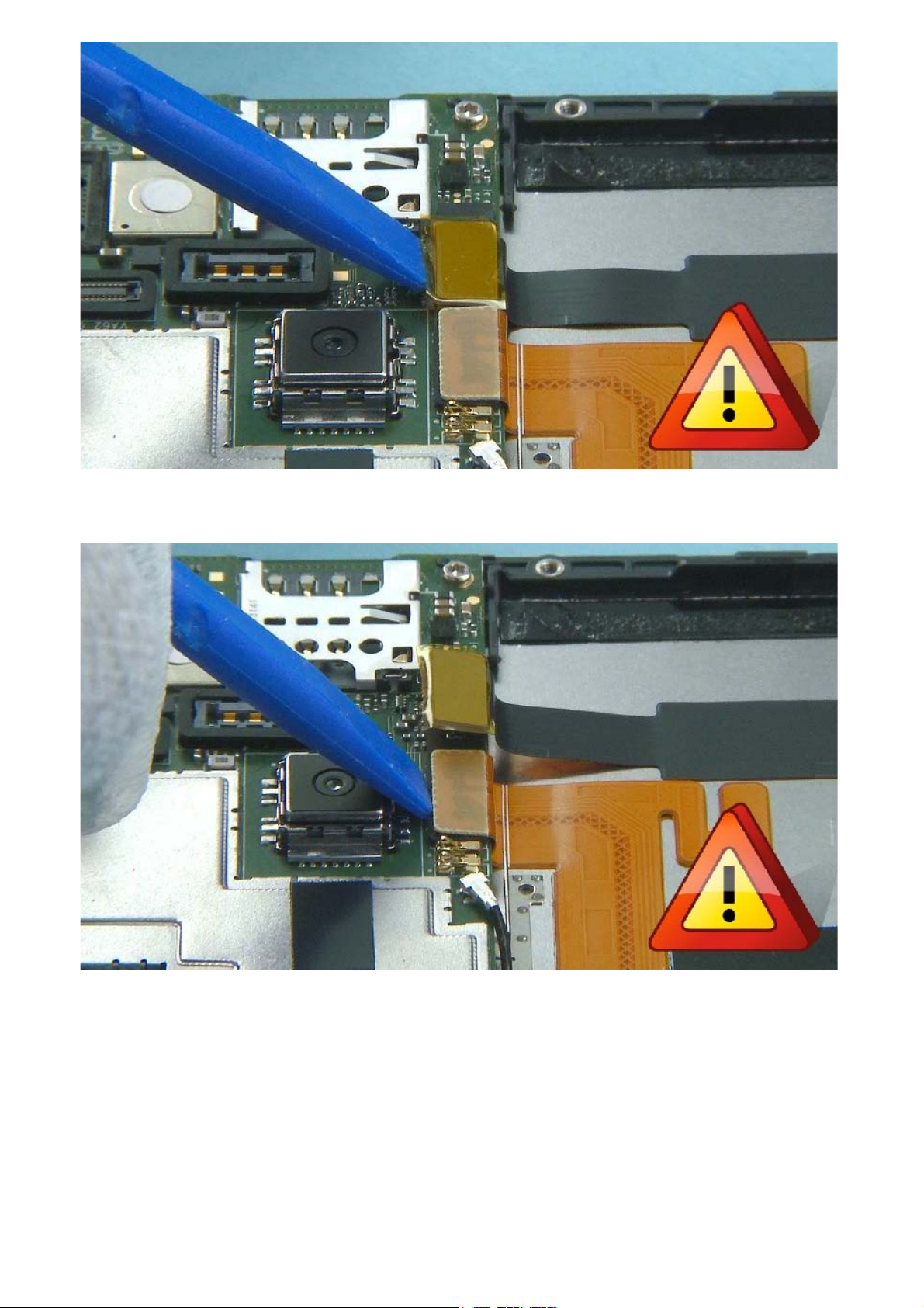
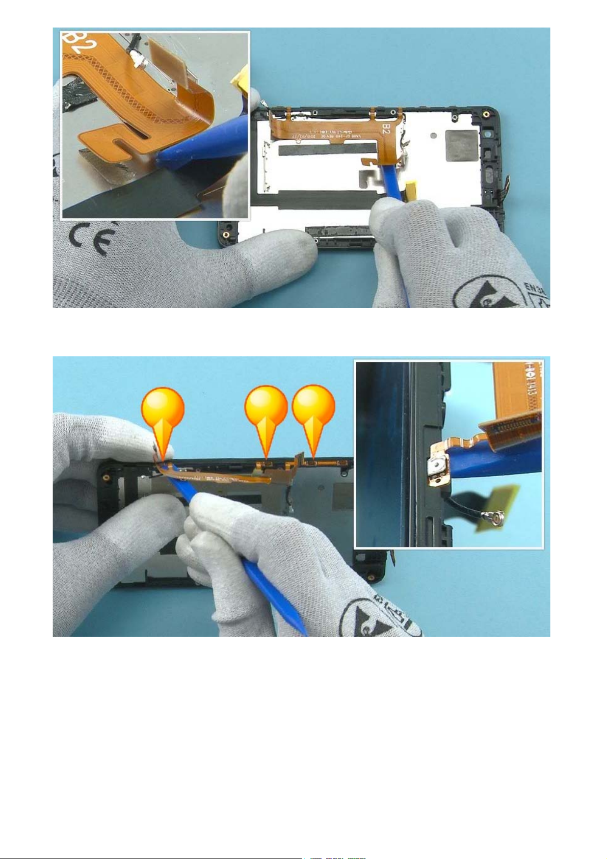
15) Open the DISPLAY connector.
16) Open the SIDE KEY FLEX connector.
Page 11
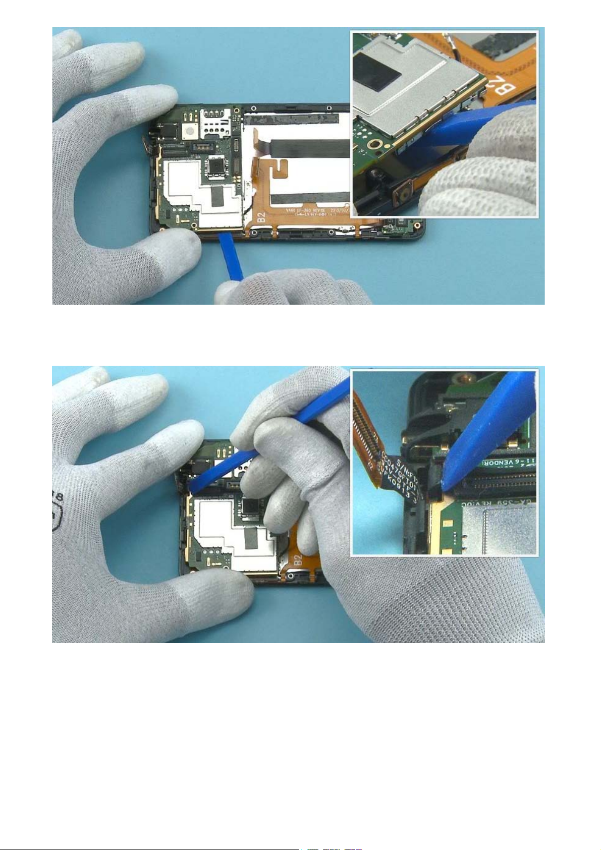
17) Open the SUB BOARD SIDE KEY FLEX connector.
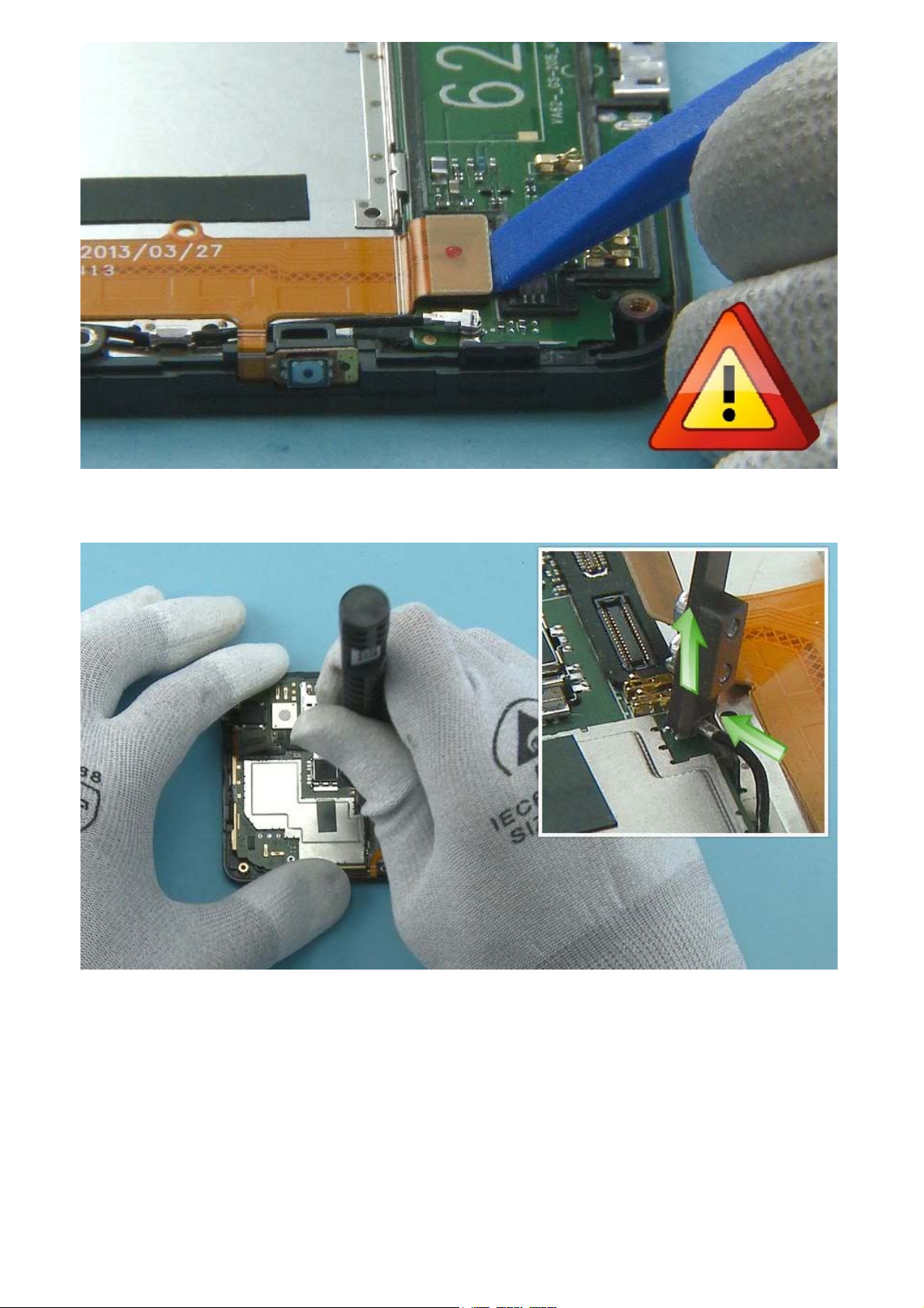
18) Release the RF-CABLE connector from the main ENGINE BOARD with the SS-231. Lock the SS-231 to
the top of the connector as shown and lift it up carefully. Note that the SS-298 can also be used to
disconnect the RF CABLE.
Page 12
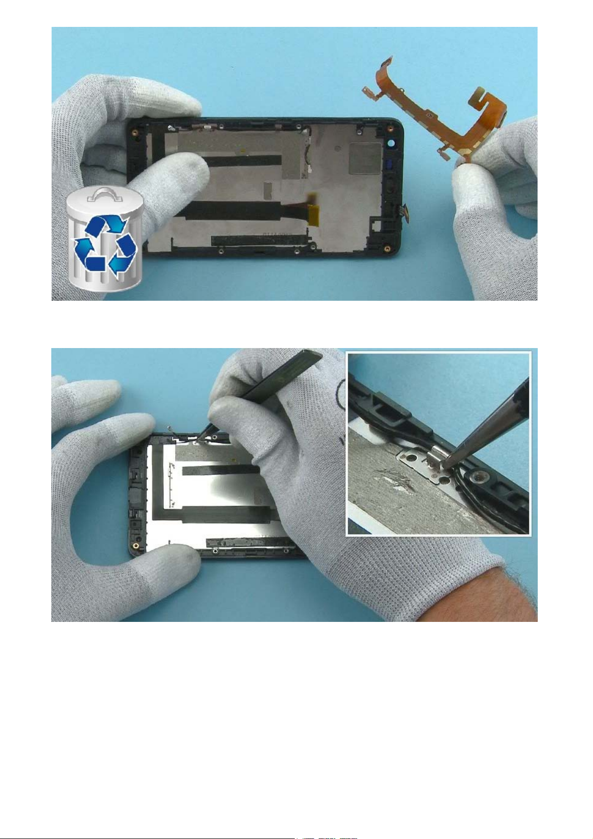
19) Release the RF CABLE connector also from the SUB BOARD side.
20) Unscrew the two Torx+ size 5 screws. Do not use the screws again. Discard them.
Page 13
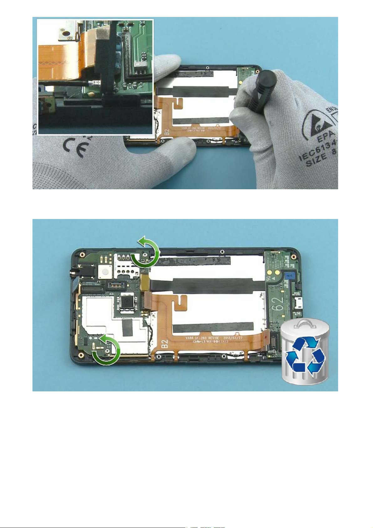
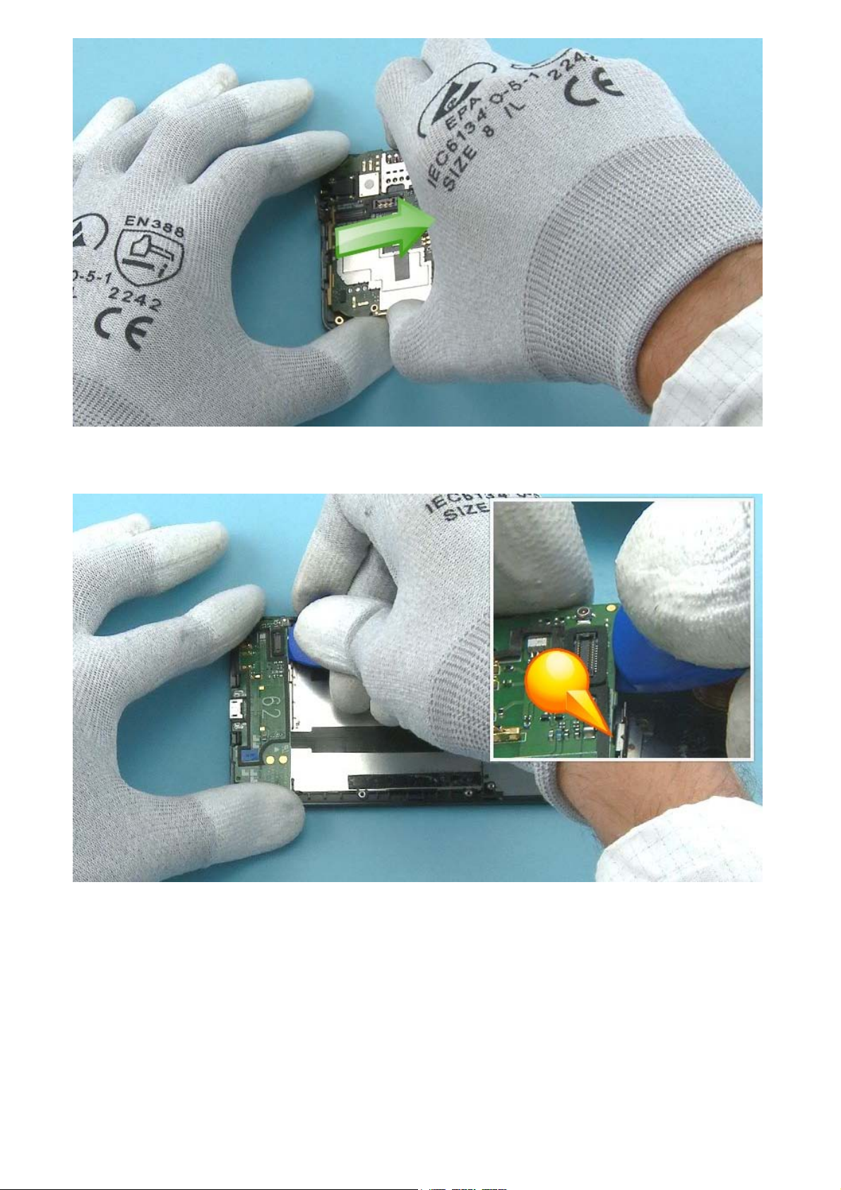
21) To remove the main ENGINE BOARD, first release the adhesive holding it from the shown side with
the SS-93.
22) Then push with SS-93 to release the clip located by the TOUCH PANEL connector.
Page 14
23) Lift up the ENGINE BOARD from the bottom end and remove it.
24) To remove the SUB BOARD, first release the shown clip with the SRT-6 from the shown place.
Page 15
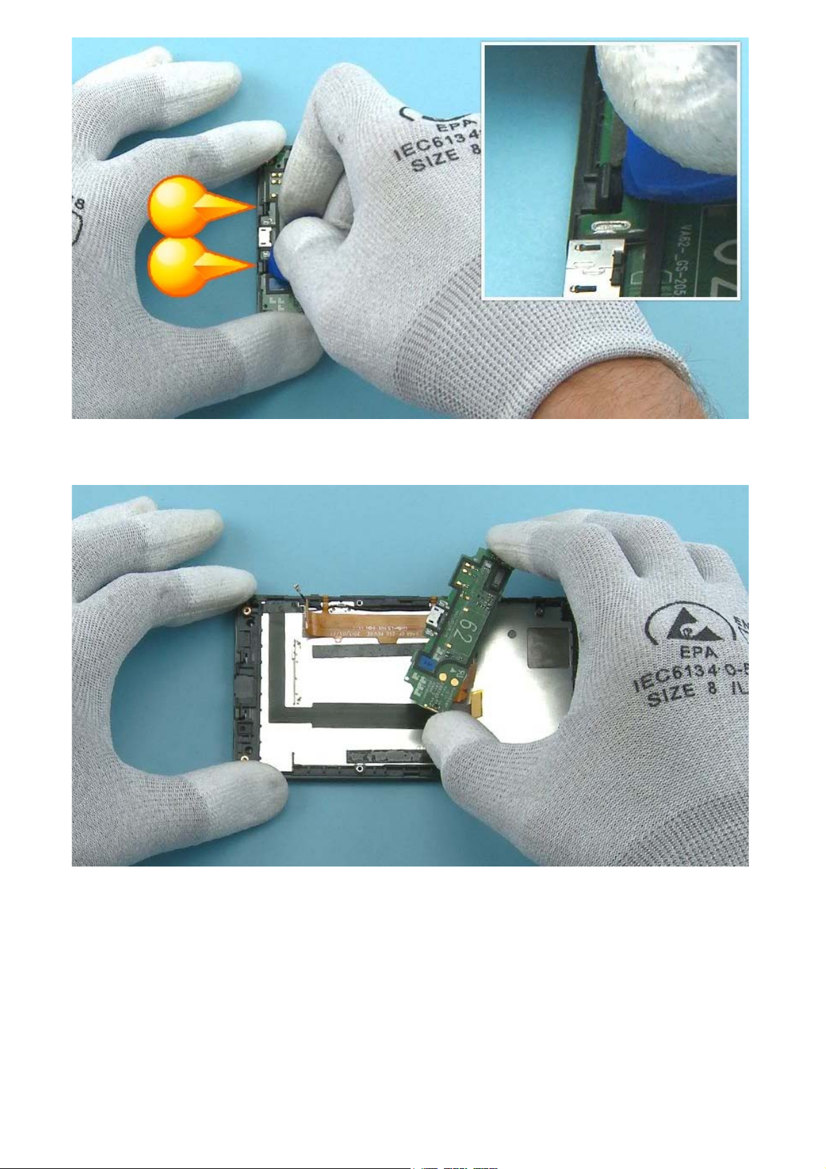
25) Then release the two clips located on both sides of the USB connector.
26) Lift up and remove the SUB BOARD.
Page 16
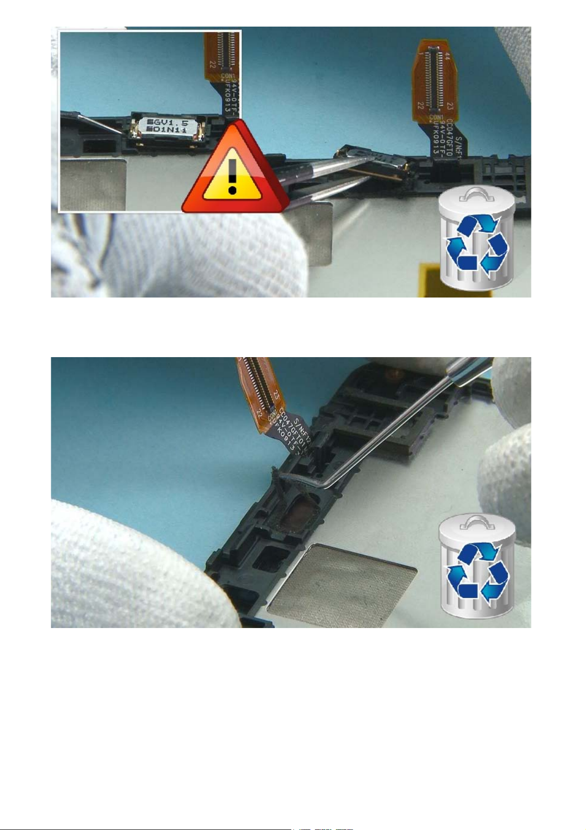
27) Release the EARPIECE with the dental tool. Be careful not to injure yourself with the sharp end of the
dental tool. Remove the EARPIECE with tweezers. Do not use it again. Discard it.
28) Remove and discard the EARPIECE ADHESIVE with the dental tool.
Page 17
29) Peel off the SIDE KEY FLEX from the A-COVER with the SS-93.
30) Then release the SIDE KEYS from the side of the A-COVER.
Page 18
31) Remove the SIDE KEY FLEX. Do not use it again. Discard it.
32) Remove the RF CABLE by first releasing it from the two metal holders on the A-COVER.
Page 19
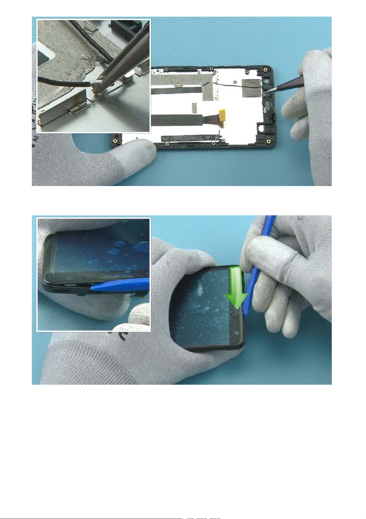
33) Grab the RF CABLE from the metal sheet and remove it.
34) Start releasing the TOUCH PANEL by inserting the SS-93 to the EARPIECE hole. Turn the SS-93
sideways and slide it to the direction shown.
Page 20
35) Then release the right side of the TOUCH PANEL by sliding the SRT-6 along the side.
36) Then release the bottom side of the TOUCH PANEL by sliding the SS-93 under it. Keep the edge of
the SS-93 outside the TOUCH PANEL to avoid damaging the sponge underneath.
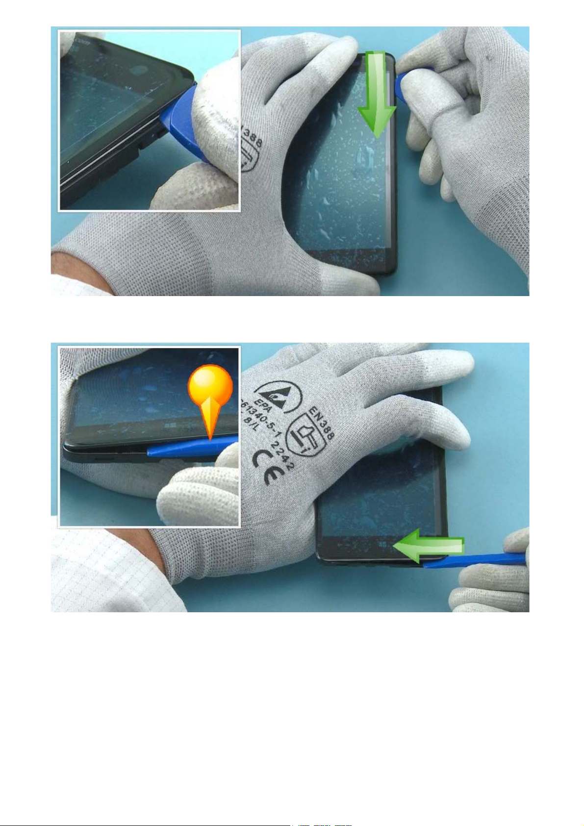
Page 21
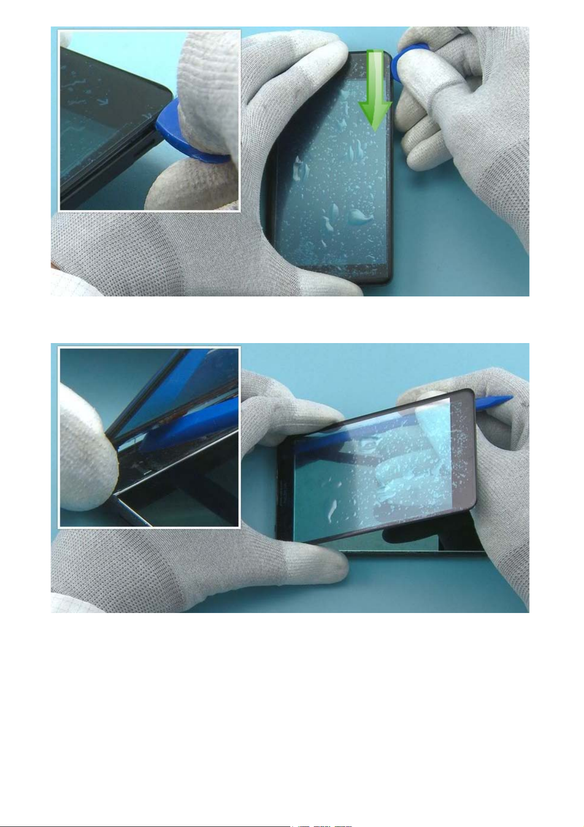
37) Then release the left side of the TOUCH PANEL by sliding the SRT-6 along the side.
38) Lift up the TOUCH PANEL from the bottom and use the SS-93 to release the rest of the adhesive
from the top end.
Page 22
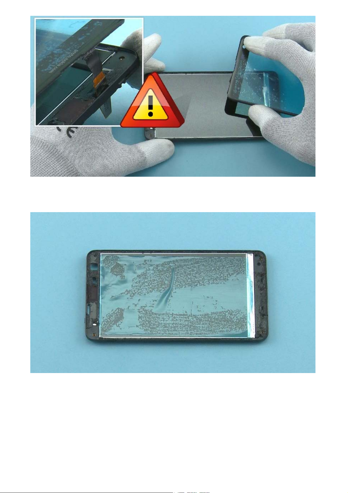
39) Remove the TOUCH PANEL. Be careful not to damage the connector when guiding it through the ACOVER.
40) Protect the DISPLAY with protective film.
Page 23

41) Remove and discard the DISPLAY MYLAR with tweezers.
42) Peel off the DISPLAY flex from the A-COVER.
Page 24
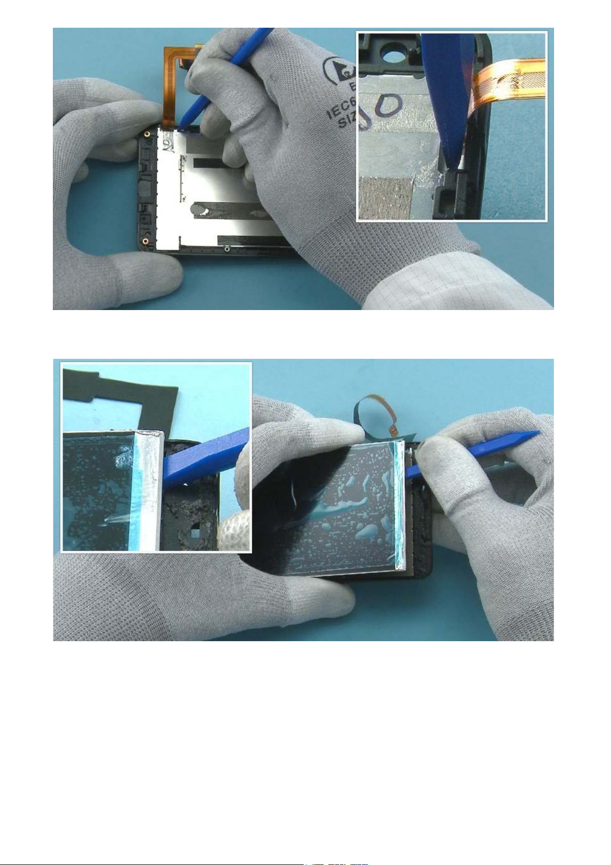
43) Release the DISPLAY by slightly pushing it out from the shown place with the sharp end of the SS-93.
44) Then carefully push the SS-93 under the DISPLAY from the shown place and release the adhesive
holding it.
Page 25

45) Lift up the DISPLAY and carefully guide the DISPLAY flex through the A-COVER. Be careful not to
damage the flex or the connector.
46) Note that if the TOUCH PANEL or the DISPLAY is removed, the A-COVER is not reusable.
Page 26

47) Peel off and discard the DISPLAY CONNECTOR FILM.
48) Peel off and discard the DISPLAY FLEX ADHESIVE with the SS-93. If available, use a hot air gun to heat
up the adhesive before peeling it off. This makes it easier to remove all of the adhesive residue.
Page 27

49) Peel off and discard the SIDE KEY FLEX adhesive with the SS-93. If available, use a hot air gun to
make the procedure easier.
50) Peel off and discard the BATTERY ADHESIVE.
Page 28

51) Peel off and discard the second BATTERY ADHESIVE.
52) Remove the PROXIMITY SENSOR RUBBER from the ENGINE BOARD with tweezers.
Page 29

53) Remove the FRONT CAMERA RUBBER.
54) Release the sides of the TOP SHIELDING LID with the dental tool.
Page 30

55) Remove and discard the TOP SHIELDING LID.
56) Remove the CAMERA by first pushing the SS-305 to the CAMERA socket.
Page 31

57) Then hold from the sides of the SS-305 and lift up the CAMERA.
58) Release the sides of the BOTTOM SHIELDING LID with the dental tool.
Page 32

59) Remove and discard the BOTTOM SHIELDING LID.
60) Remove and discard the TOUCH PANEL CONNECTOR RUBBER with tweezers.
Page 33

61) Remove and discard the BATTERY CONNECTOR RUBBER.
62) Remove and discard the DISPLAY AND SIDE KEY CONNECTOR RUBBER.
Page 34

63) Remove and discard the AV CONNECTOR SPONGE.
64) Remove and discard the SIDE KEY SUB BOARD CONNECTOR RUBBER.
Page 35

65) Remove and discard the SPEAKER SEALING SPONGE.
66) Release the LED FLASH FLEX with the dental tool and remove it with tweezers.
Page 36

67) Release the IHF SPEAKER with the dental tool and remove it with tweezers.
68) Remove and discard the SPEAKER ADHESIVE with the dental tool.
Page 37

69) Remove and discard the SPEAKER ADHESIVE residue from the IHF SPEAKER.
70) Release the VIBRA with the sharp end of the SS-93 and remove it with tweezers.
Page 38

71) The Nokia Lumia 625 disassembly procedure is complete.
-END OF DISASSEMBLY-
©2013 Nokia | Nokia Internal Use only | All Rights Reserved.
Page 39

Service Manual Level 1 and 2
Nokia Lumia 625
RM- 941, RM-942, RM-943
Version 1.0
Assembly steps
1) For assembling you need the Nokia Standard Tool kit version 2. You will also need the RF connector
disassembly/assembly tool SS-231 or the SS-298.
2) Peel off the protective film from the A-COVER.
Page 40

3) Guide the DISPLAY flex through the A-COVER. Be careful not to damage the DISPLAY connector or the
flex.
4) Place the DISPLAY on the A-COVER bottom end first and then lower down the other end.
Page 41

5) Peel off the DISPLAY FLEX ADHESIVE protective film.
6) Attach the DISPLAY flex to the A-COVER.
Page 42

7) Use the guiding lines on the A-COVER to get the right alignment. Press firmly to activate the adhesive.
8) Place the DISPLAY MYLAR to its place.
Page 43

9) Remove the protective film from the inner side of the TOUCH PANEL.
10) Remove the DISPLAY protective film.
Page 44

11) Assemble the TOUCH PANEL to the A-COVER top end first. Be careful not to damage the TOUCH
PANEL connector when guiding it through the A-COVER.
12) Lower down the bottom end of the TOUCH PANEL.
Page 45

13) Press around the device to get the TOUCH PANEL firmly attached.
14) Assemble the RF CABLE to the A-COVER. Attach the metal sheet of the RF CABLE to the metal holder
on the A-COVER. Make sure the RF CABLE goes around the shown corner.
Page 46

15) Attach also the other metal sheet of the RF CABLE.
16) Remove the protective films from SIDE KEY FLEX.
Page 47

17) Remove the protective films also from SIDE KEYS.
18) Attach the SIDE KEY FLEX to the A-COVER. Use the guiding lines on the A-COVER to get the right
alignment.
Page 48

19) Press firmly to activate the adhesive.
20) Then attach the SIDE KEYS to the side of the A-COVER.
Page 49

21) Use the sharp end of the SS-93 to bend the flexes as shown so that there is no extra space between
the flexes and the A-COVER and the RF CABLE.
22) Remove the EARPIECE ADHESIVE protective film from the EARPIECE slot.
Page 50

23) Place the EARPIECE to its place and press it gently. Make sure the two shown pins are facing the right
way.
24) Peel off the BATTERY ADHESIVE protective film.
Page 51

25) Place the second BATTERY ADHESIVE to the shown place. Use the guiding line on the A-COVER to get
the right positioning.
26) Press firmly and remove the protective film.
Page 52

27) When assembling the ENGINE BOARD and the SUB BOARD be careful not to damage any components.
28) Place the BOTTOM SHIELDING LID to the ENGINE BOARD. Press from the sides with the SS-93 to get
it properly attached.
Page 53

29) Place the CAMERA to the CAMERA socket with tweezers. Make sure the shown clip is facing the right
way.
30) Carefully press the CAMERA inside the socket from the sides with the SS-93.
Page 54

31) Place the TOUCH PANEL CONNECTOR RUBBER to its place with tweezers.
32) Place the BATTERY CONNECTOR RUBBER to its place.
Page 55

33) Place the DISPLAY AND SIDE KEY CONNECTOR RUBBER to its place.
34) Place the AV CONNECTOR SPONGE to its place.
Page 56

35) Place the TOP SHIELDING LID to the ENGINE BOARD. Press from the sides with the SS-93 to get it
completely attached.
36) Place the FRONT CAMERA RUBBER to its place.
Page 57

37) Place the PROXIMITY SENSOR RUBBER to its place.
38) Place the SPEAKER SEALING SPONGE on the SUB BOARD. Use the guiding lines on the SUB BOARD to
get the right placement.
Page 58

39) Press around the sponge and peel off the protective film.
40) Place the SIDE KEY SUB BOARD CONNECTOR RUBBER to its place.
Page 59

41) Assemble the SUB BOARD to the A-COVER shown side first. Press it towards the bottom of the
device to attach the two shown clips.
42) Then press by the connector to attach the shown clip.
Page 60

43) Place the ENGINE BOARD on the A-COVER. Align the two screw holes.
44) Press from the shown place to attach the shown clip.
Page 61

45) Fasten the two Torx+ size 5 screws in the order shown to the torque of 9.8 +/- 1 Ncm.
46) Connect the RF CABLE connector to the SUB BOARD with the SS-231. Lock the SS-231 to the top of
the connector as shown and press down gently. Note that the SS-298 can also be used to connect the
RF CABLE.
Page 62

47) Connect the other end of the RF CABLE to the ENGINE BOARD.
48) Connect both of the SIDE KEY FLEX connectors, then the DISPLAY connector and the TOUCH PANEL
connector. Be careful not to damage the connectors or any nearby components.
Page 63

49) Make sure the flexes fold firmly to the A-COVER. Fold the flexes with the SS-93 if needed.
50) Place the DISPLAY connector protective film to its place.
Page 64

51) Peel off the middle part of the BATTERY MYLAR protective film. Place the BATTERY MYLAR on the
BATTERY as shown.
52) Peel off the sides of the protective film from the BATTERY MYLAR and press around firmly to get the
BATTERY MYLAR properly attached.
Page 65

53) Place the BATTERY to the BATTERY compartment top end first.
54) Lower down the bottom end and press to activate the adhesive.
Page 66

55) Connect the BATTERY connector.
56) Place the LED FLASH FLEX to the D-COVER with tweezers and press it gently with the SS-93 to get it
firmly in place.
Page 67

57) Place the VIBRA to its place and press gently to activate the adhesive.
58) Peel off the SPEAKER ADHESIVE protective film.
Page 68

59) Place the IHF SPEAKER to its place and press gently to activate the adhesive. Make sure the shown
pins are facing the right way.
60) Place the D-COVER on the device.
Page 69

61) Press together all the sides of the device to get the D-COVER firmly attached.
62) Fasten the first four Torx+ size 5 screws in the order shown to the torque of 9.8 +/- 1 Ncm.
Page 70

63) Then fasten the remaining four Torx+ size 5 screws in the order shown to the torque of 5 +/- 1 Ncm.
64) Assemble the BATTERY COVER top end first, then lower down the bottom end.
Page 71

65) Press from the sides of the device to get the BATTERY COVER firmly attached.
66) The Nokia Lumia 625 assembly procedure is complete.
-END OF ASSEMBLY-
©2013 Nokia | Nokia Internal Use only | All Rights Reserved.
Page 72

Service Manual Level 1 and 2
Nokia Lumia 625
RM-941, RM-942, RM-943
Version 1.0
TOP
Solder components
BOTTOM
GPS Antenna
spring
S3500
MIMO Antenna
GND spring
GPS Antenna
GND spring
S3501
S2600S2601
MIMO Antenna
spring
Battery
connector
J1100
SP1603 F300SP1602
LED Flash
GND spring
LED Flash
spring
Current
fuse
©2013 Nokia | Confidential | All Rights Reserved.
Page 73

Service Manual Level 1 and 2
s
Nokia Lumia 625
RM-941, RM-942, RM-943
Version 1.0
Service device
CA-101 Service cable AC-20 Fast USB charger
(AC-21 for China, AC-10UC for Taiwan)
SS-231/SS-298 RF connector
disassembly/assembly tool
Bulletin (SB-011) on Nokia Online. Supplier or
manufacturer contacts for tool re-order can
©2013 Nokia | Nokia Internal Use only | All Rights Reserved.
Nokia Standard Toolkit (v2)
For more information, refer to the Service
be found in “Recommended service
equipment” document on Nokia Online.
SS-305 Camera removal tool
Page 74

Service Manual Level 1 and 2
Nokia Lumia 625
RM-941, RM-942, RM-943
Version 1.0
Product controls and interfaces
10
1
1 — 3.5 mm headset connector
2 — Earpiece
2
3
4
3 — Front camera
4 — Ambient light & proximity sensor
5 — Touch screen
6 — Back key
7 — Search key
8 — Start key
5
9 — Microphone
10 — Micro-USB connector
11 — Camera flash
12 — Camera lens
6
7
8
9
13 — Volume keys
14 — Power/lock key
15 — Camera key
16 — Loudspeaker
17 — MIMO antenna
11
12
13
14
15
16
18 — Cellular antenna
19 — Bluetooth, Wi-Fi & GPS antenna
1917
18
©2013 Nokia | Nokia Internal Use only | All Rights Reserved.
Page 75

Service Manual Level 1 and 2
Nokia Lumia 625
RM-941, RM-942, RM-943
Version 1.0
Flashing concept
Service
software
Service concept
CA-101
Note: Charged
battery is mandatory
Transceiver with
embedded battery
©2013 Nokia | Nokia Internal Use only | All Rights Reserved.
Page 76

Service Manual Level 1 and 2
0
t
u
Nokia Lumia 625
RM-941, RM-942, RM-943
Version 1.
Phone rese
Hardware reset
If the phone hardware is jammed, you should first recommend that
the consumer performs a hardware reset. The hardware reset does
not reset the Windows Live ID or remove any consumer data. Because
the consumer cannot remove the battery to reset the phone the
phone has a special electronic circuit which cuts the phone power
when the volume down and power keys are pressed for 10-15
seconds.
To perform the hardware reset, press and hold the Volume down and
Power keys at the same time for about 10-15 seconds until a short
vibration is felt. The phone should restart by itself.
Software / operating system (OS) reset
The software / operating system (OS) reset returns the phone to its out-of-the-box state. Note that this
procedure erases all consumer data! Always first try to perform a hardware reset.
Option 1: About men
- Use this option if the consumer knows the lock code
- This option warns the consumer about data loss!
-Tap Settings > About > reset your phone
Page 77

Option 2: Hardware key combination
- Use this option if the phone is locked and the consumer does not know the code
- Note: no warning about data loss!
- Do not advertise this feature to consumers!
Follow next steps to perform OS reset with phone keys.
Step 1
Make sure the phone is turned Off.
1. Press and hold the power key
2. Phone vibrates (release the
power key)
3. Press and hold the volume
down key
4. Exclamation mark is shown on
the screen (release the volume
down key)
Step 2
Input the following key
combination:
1. Volume up
2. Volume down
3. Power
4. Volume down
Step 3
The phone will reset and boot up
automatically
©2013 Nokia | Nokia Internal Use only | All Rights Reserved.
Page 78

Service Manual Level 1 and 2
V
Nokia Lumia 625
RM-941, RM-942, RM-943
Version 1.0
Version Date Description
1.0 24.07.2013 First published version
ersion history
©2013 Nokia | Nokia Internal Use only | All Rights Reserved.
 Loading...