

Page 1
Service Manual for L1 and L2
Nokia Lumia 610
RM-835 RM-836
Key features
Most affordable Nokia Lumia yet
Updated Windows Phone operating system
8 GB internal mass memory
3.7" WVGA 800 x 480 pixels LCD TFT display
Version 1.0
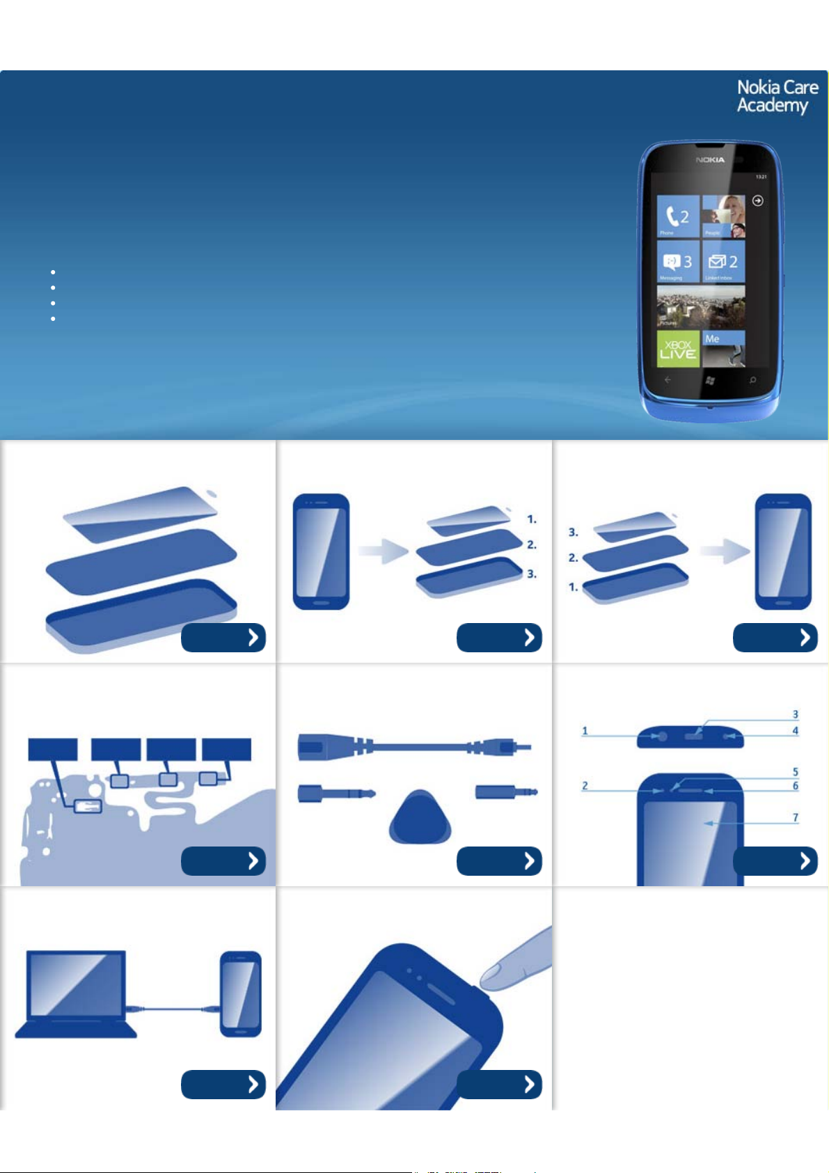
Exploded view Disassembly steps Assembly steps
More More More
Solder components Service devices Product controls and interfaces
More More More
Service concept Phone reset
More More
©2012 Nokia | Nokia Internal Use only | All Rights Reserved.
Page 2
Service Manual Level 1 and 2
Nokia Lumia 610
RM-835 RM-836
Version 1.0
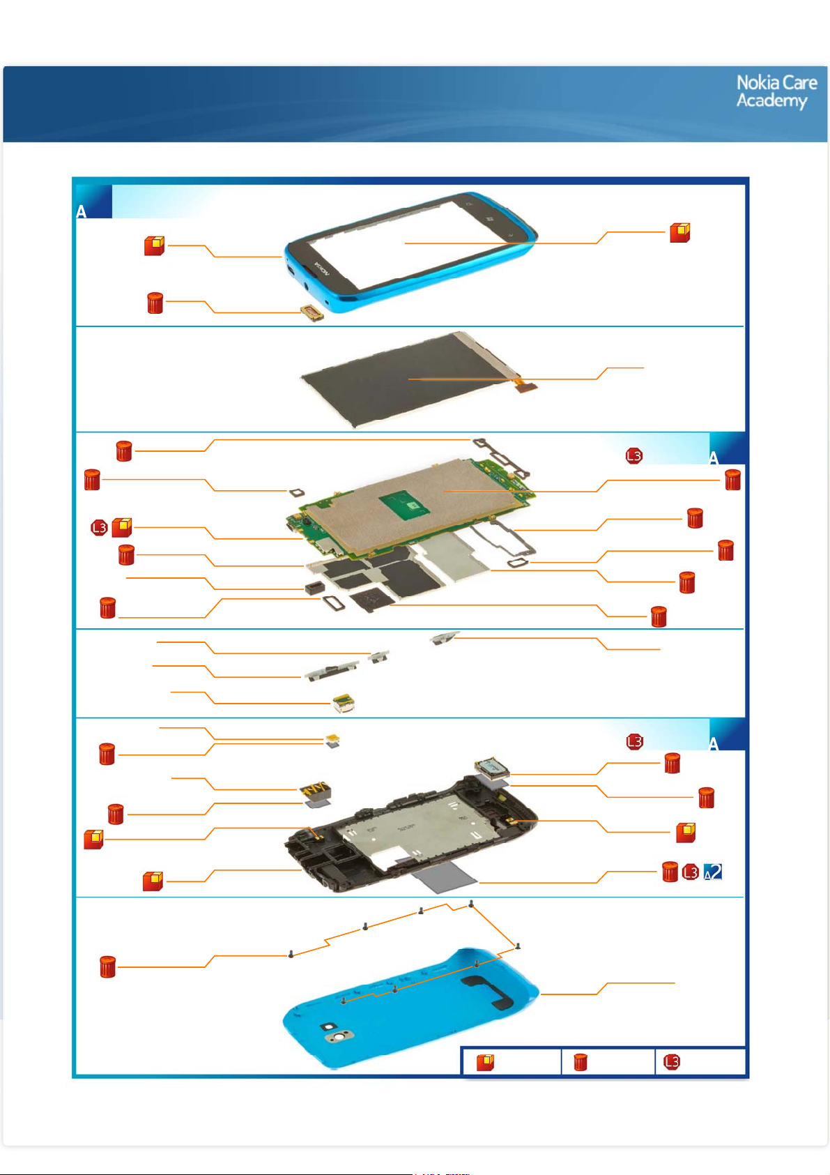
A-COVER ASSEMBLY
(I0001 - I0003)
1
A-COVER
I0002
EARPIECE
I0003
Exploded view
TOUCH PANEL
I0001
DISPLAY
I0007
KEY LED RUBBER
SECONDARY MIC RUBBER
LIGHT SWAP PWB
SHIELDING LID 2
LED FLASH RUBBER
CONNECTOR RUBBER
LED FLASH ADHESIVE
AV JACK ADHESIVE
BT/GPS/WLAN ANTENNA
I0009
I0008
I0018
I0016
I0017
TOUCH PANEL
I0012
POWER KEY
I0006
VOLUME KEY
I0004
CAMERA
I0020
LED FLASH
I0025
I0026
AV JACK
I0023
I0024
I0028
D-COVER
I0029
LIGHT SWAP PACKAGE
D-COVER ASSEMBLY
(I0008 - I0019)
DISPLAY CONDUCTIVE TAPE
I0010
ANTENNA RUBBER
I0014
LCD CONNECTOR RUBBER
I0011
SHIELDING LID 1
I0015
SIM TAPE
I0013
CAMERA KEY
I0005
(I0021 - I0029)
IHF SPEAKER
I0021
IHF SPEAKER GASKET
I0022
MAIN ANTENNA
I0027
TYPE LABEL
I0019
2
3
SCREW TORX+ SIZE 4
I0030
Only available
as assembly
©2012 Nokia | Nokia Internal Use only | All Rights Reserved.
BATTERY COVER
I0031
Not reuseable
after removal
Repair/swap
only in level 3
Page 3
Service Manual Level 1 and 2
Nokia Lumia 610
RM- 835, RM -836
Version 1.0
Disassembly steps
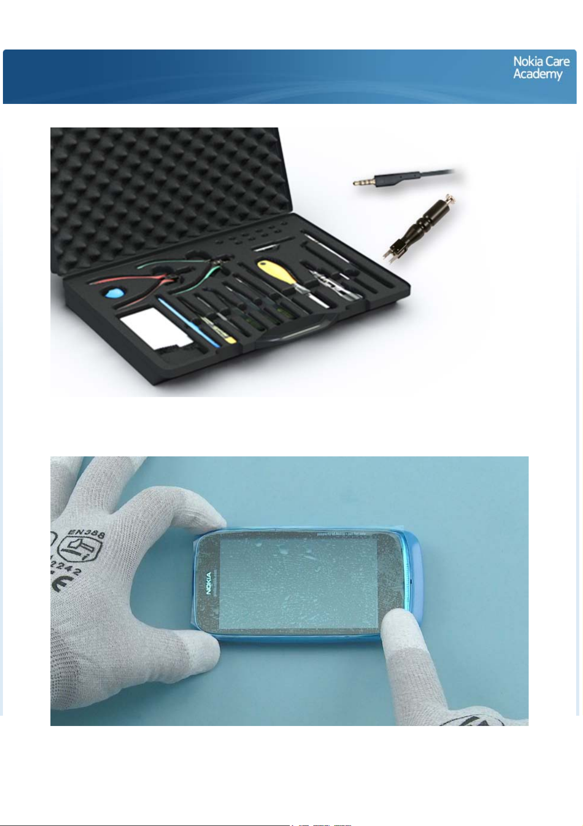
For disassembling you need the Nokia Standard toolkit version 2. You will also need the camera removal
tool SS-287 and an AV plug.
Protect the A-COVER with protective film.
Page 4
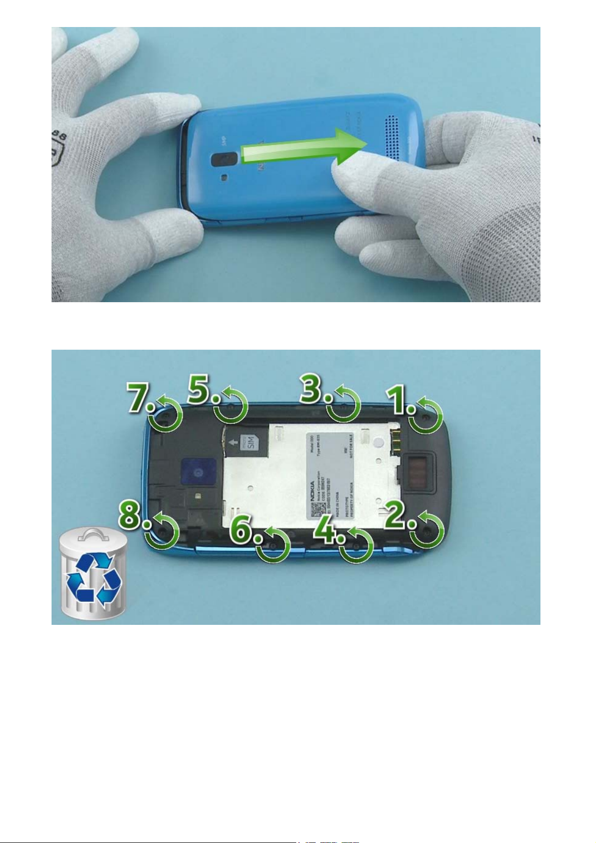
Open the BATTERY COVER by pulling it to the direction shown. Remove the BATTERY COVER.
Unscrew the eight Torx+ size 4 screws in the order shown. Do not use them again. Discard them.
Page 5
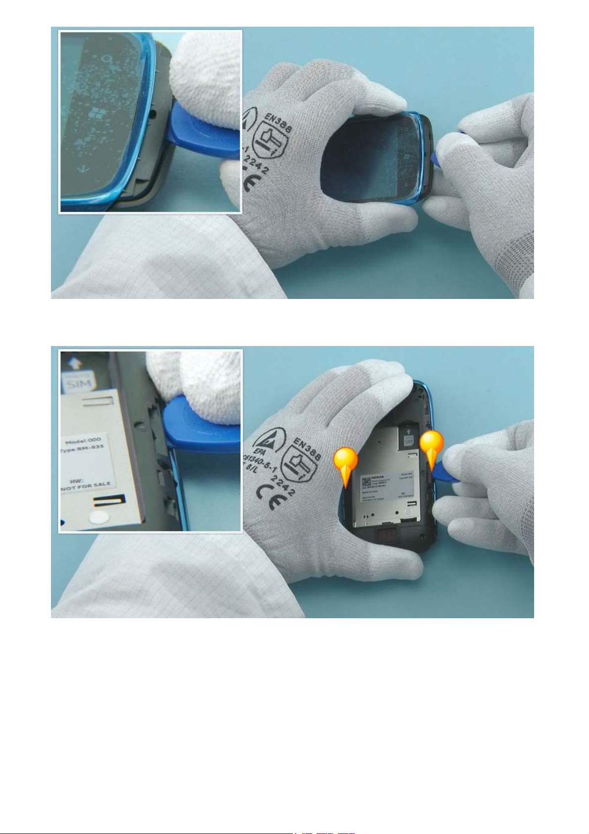
Insert the SRT-6 to the shown place and release the bottom end of the D-COVER.
Release also both sides of the D-COVER with the SRT-6.
Page 6
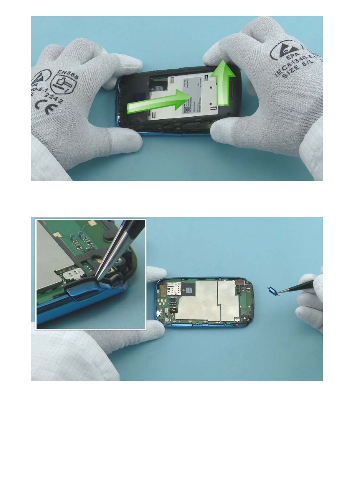
Lift up the bottom end of the D-COVER and pull it to the direction shown. The D-COVER can now be
separated.
Remove the CAMERA KEY with tweezers.
Page 7
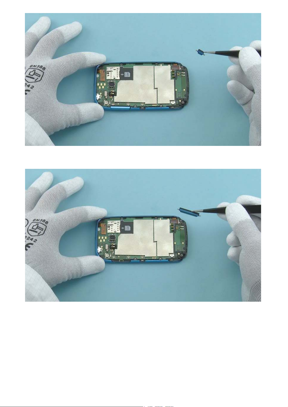
Remove the POWER KEY with tweezers.
Remove the VOLUME KEY with tweezers.
Page 8
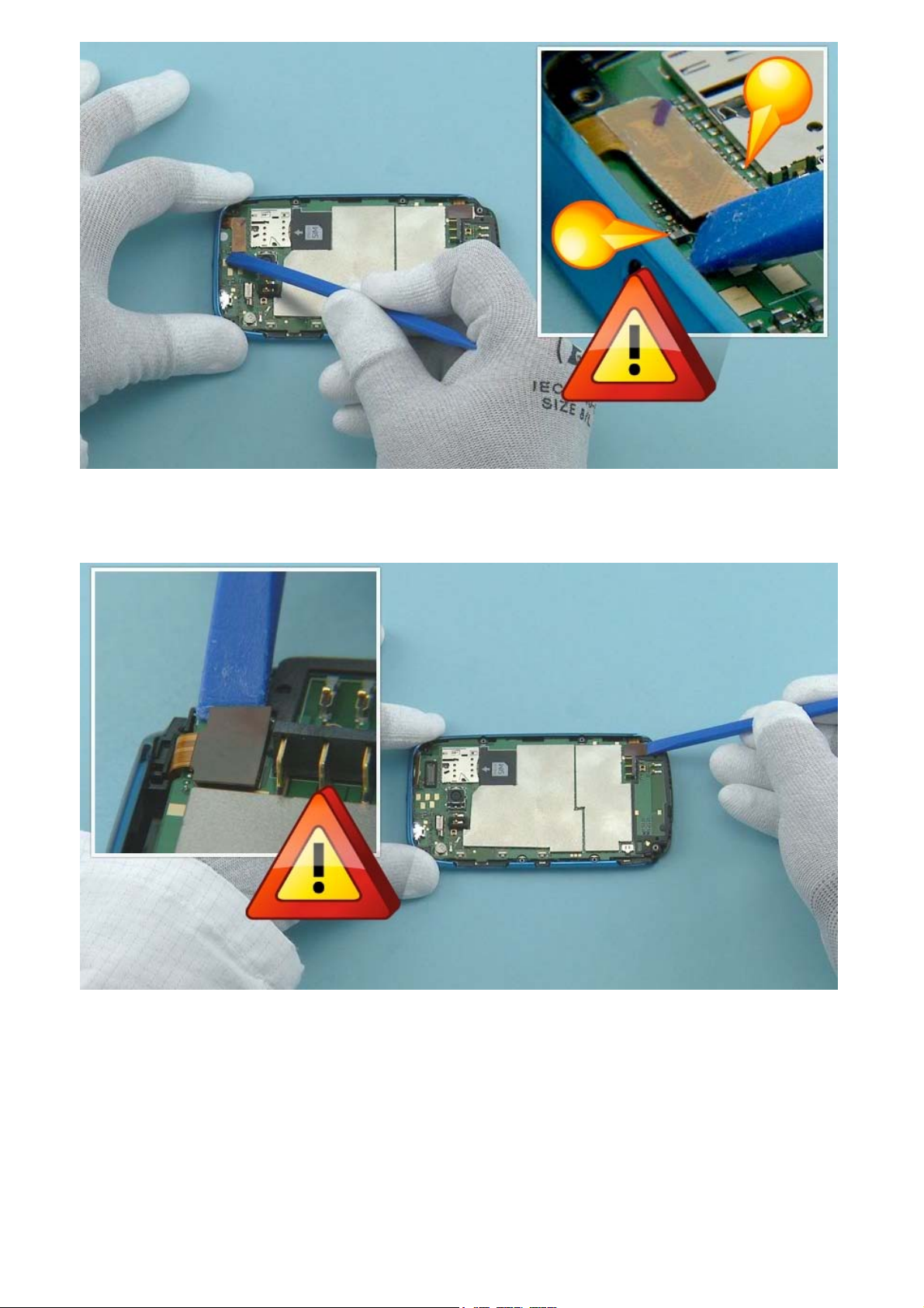
Use the SS-93 to open the TOUCH PANEL connector. Be very careful not to damage the connector or
the small components around the connector.
Open the DISPLAY connector with the SS-93. Be careful not to damage the connector or components
nearby.
Page 9
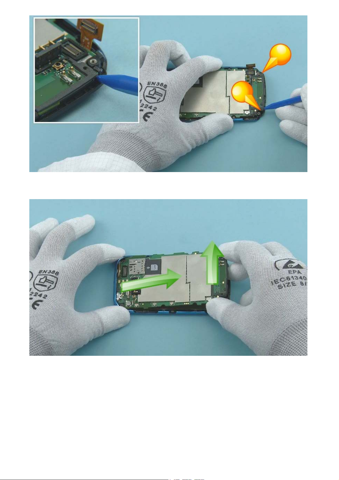
Open the two shown clips holding the ENGINE BOARD with the sharp end of the SS-93.
Lift up the bottom end of the ENGINE BOARD and pull it to the direction shown. The ENGINE BOARD can
now be separated.
Page 10

Lift up the DISPLAY with the SS-93 and remove it.
Protect the other side of the A-COVER with protective film.
Page 11

Protect the DISPLAY with protective film.
Release the EARPIECE with the dental tool. Be careful not to injure yourself with the sharp end of the
dental tool! Remove the EARPIECE with tweezers. Do not use it again. Discard it.
Page 12

Remove the EARPIECE adhesive remains from the A-COVER. Discard them.
Release the IHF SPEAKER with the SS-93 as shown.
Page 13

Remove the IHF SPEAKER and discard it.
Remove the IHF SPEAKER GASKET. The IHF SPEAKER GASKET is not reusable. Disacrd it.
Page 14

Lift up and remove the AV JACK with an AV plug.
Remove the AV JACK ADHESIVE from the D-COVER. Do not use it again.
Page 15

Push the LED FLASH gently with the sharp end of the SS-93. Remove the LED FLASH with tweezers.
Remove the LED FLASH ADHESIVE. Discard it.
Page 16

Release the LED FLASH RUBBER with the dental tool. Be careful not to damage the nearby components.
Remove the LED FLASH RUBBER with tweezers.
Remove the CAMERA with the camera removal tool SS-287. Please note that the tool used in this picture
is not SS-287.
Page 17

Release the SHIELDING LID 2 with the SS-93. Remove it with tweezers and discard it.
Release also the SHIELDING LID 1 with the SS-93. Remove it with tweezers. Do not use it again. Discard
it.
Page 18

Release the LCD CONNECTOR RUBBER with the dental tool. Be careful not to damage the nearby
components. Remove it with tweezers. Do not use it again. Discard it.
Release the TOUCH PANEL CONNECTOR RUBBER with the dental tool. Be careful not to damage the
nearby components. Remove it with tweezers. Do not use it again. Discard it.
Page 19

Lift up the SIM TAPE with the dental tool. Be careful not to damage the nearby components. Remove it
with tweezers. Do not use it again. Discard it.
Release the ANTENNA RUBBER with the dental tool. Be careful not to damage the nearby components.
Remove it with tweezers. Discard it.
Page 20

Release the SECONDARY MIC RUBBER with the dental tool. Be careful not to damage the SECONDARY MIC
or any nearby components. Remove it with tweezers. Do not use it again.
Release the KEY LED RUBBER with the dental tool. Be careful not to damage the nearby components.
Remove it with tweezers. Do not use it again. Discard it.
Page 21

Release one corner of the DISPLAY CONDUCTIVE TAPE with the dental tool. Be careful not to damage the
ENGINE BOARD. Slowly peel off the DISPLAY CONDUCTIVE TAPE.
The DISPLAY CONDUCTIVE TAPE is not reusable. Discard it.
Page 22

Remove the DISPLAY CONDUCTIVE TAPE adhesive remains from the engine board with the SS-93.
The Nokia Lumia 610 disassembly procedure is complete.
-END OF DISASSEMBLY-
©2012 Nokia | Nokia Internal Use only | All Rights Reserved.
Page 23

Service Manual Level 1 and 2
Nokia Lumia 610
RM- 835 RM -836
Version 1.0
Assembly steps
Fasten the eight Torx+ size 4 screws to the torque of 9 Ncm in the order shown.
©2012 Nokia | Nokia Internal Use only | All Rights Reserved.
Page 24

Service Manual Level 1 and 2
Nokia Lumia 610
RM-835 RM-836
Version 1.0
Solder components
Grounding
spring
PAD3902
PAD3911PAD3901 LED3705
Grounding
spring
Grounding
spring
Grounding
spring
Grounding
spring
Grounding
spring
PAD3906 PAD3910
PAD3903 PAD3905
Grounding
spring
Grounding
spring
Search key
LED
PAD3907
Grounding
spring
Start key
LED
Back key
LED
BOTTOM
USB
Fuse
F1601
v1.0
LED flash
connector
PD2302 PD2301
PAD3501
BT/WLAN/GPS
LED flash
connector
up switch
Volume
BT/WLAN/GPS
antenna connector
PAD3502
Volume
down switch
RF antenna
spring connector
RF antenna
spring connector
PAD3202 PAD3201 SH11
SK3702SK3701SK3704SK3703
Power
switch
Camera
switch
Grounding
spring
©2012 Nokia | Confidential | All Rights Reserved.
Page 25

Service Manual Level 1 and 2
V
0
s
Nokia Lumia 610
RM-835 RM-836
ersion 1.
Service device
CA-190CD Service cable AC-50 USB charger SS-287 Camera removal tool
Nokia Standard Toolkit (v2)
For more information, refer to the Service
Bulletin (SB-011) on Nokia Online. Supplier or
manufacturer contacts for tool re-order can be
found in “Recommended service equipment”
document on Nokia Online.
©2012 Nokia | Nokia Internal Use only | All Rights Reserved.
Page 26

Service Manual Level 1 and 2
Nokia Lumia 610
RM-835 RM-836
Version 1.0
Product controls and interfaces
1
2
9
11
10
3
4
5
1 — Strap holder
2 — Nokia AV 3.5 mm connector
3 — Micro USB connector
6
4 — Secondary microphone
5 — Earpiece
6 — Ambient light &
Proximity sensor
7 — Touch screen
7
8 — Start key
9 — Back key
10 — Search key
11 — Microphone
8
12 — Camera
13 — Camera flash
14 — Volume keys
15 — Power/Lock key
16 — Camera key
12
13
17
17 — Loudspeaker
14
15
16
©2012 Nokia | Nokia Internal Use only | All Rights Reserved.
Page 27

Service Manual Level 1 and 2
Nokia Lumia 610
RM-835 RM-836
Version 1.0
Flashing concept
Service concept
Service
CA-101
software
On Device Diagnostics Tool (ODDT)
The ODDT is an app for performing basic device hardware
troubleshooting at Nokia Care Points. The ODDT is not visible on
retail phones and it is intended only for use by trained personnel at
Nokia Care Points.
Care Dummy Bat tery with power
supply via Nokia
charger or product
specific battery
Transceiver
To install the ODDT:
1. Enter ##634# on the on-screen keypad
2. Diagnostics app appears in Apps list
To remove the ODDT:
1. Tap and hold Diagnostics
2. Tap uninstall
Note: always uninstall the tool before returning the phone to the
consumer!
For more information on using the ODDT, see KICS TR2816.
©2012 Nokia | Nokia Internal Use only | All Rights Reserved.
Page 28

Service Manual Level 1 and 2
0
u
Nokia Lumia 610
RM-835 RM-836
Version 1.
Phone reset
Hardware reset
If the phone hardware is jammed, you should first
recommend that the consumer performs a hardware reset.
The hardware reset does not reset the Windows Live ID or
remove any consumer data.
To perform a hardware reset remove the battery and
reinsert it. Boot up the phone normally.
Software / operating system (OS) reset
The software / operating system (OS) reset returns the phone to its out-of-the-box state. Note that this
procedure erases all consumer data! Always first try to perform a hardware reset.
About men
- Use this procedure if the consumer knows the lock code
- This procedure warns the consumer about data loss!
-Tap Settings > About > reset your phone
Note
- Nokia Lumia 610 does not support OS reset using hardware keys!
©2012 Nokia | Nokia Internal Use only | All Rights Reserved.
Page 29

Service Manual Level 1 and 2
Nokia Lumia 610
RM- 835 RM -836
Version 1.0
Version Date Description
1.0 05.03.2012 First published version
Version history
©2012 Nokia | Nokia Internal Use only | All Rights Reserved.
 Loading...