

Page 1

Nokia Customer Care
Service Manual
RM-645 (Nokia C5-00; L3&4)
Mobile Terminal
Part No: (Issue 1)
COMPANY CONFIDENTIAL
Copyright © 2010 Nokia. All rights reserved.
Page 2

Amendment Record Sheet
Amendment No Date Inserted By Comments
Issue 1 03/2010 MT
RM-645
Amendment Record Sheet
Page ii COMPANY CONFIDENTIAL Issue 1
Copyright © 2010 Nokia. All rights reserved.
Page 3

RM-645
Copyright
Copyright
Copyright © 2010 Nokia. All rights reserved.
Reproduction, transfer, distribution or storage of part or all of the contents in this document in any form
without the prior written permission of Nokia is prohibited.
Nokia, Nokia Connecting People, and Nokia X and Y are trademarks or registered trademarks of Nokia
Corporation. Other product and company names mentioned herein may be trademarks or tradenames of
their respective owners.
Nokia operates a policy of continuous development. Nokia reserves the right to make changes and
improvements to any of the products described in this document without prior notice.
Under no circumstances shall Nokia be responsible for any loss of data or income or any special, incidental,
consequential or indirect damages howsoever caused.
The contents of this document are provided "as is". Except as required by applicable law, no warranties of
any kind, either express or implied, including, but not limited to, the implied warranties of merchantability
and fitness for a particular purpose, are made in relation to the accuracy, reliability or contents of this
document. Nokia reserves the right to revise this document or withdraw it at any time without prior notice.
The availability of particular products may vary by region.
IMPORTANT
This document is intended for use by qualified service personnel only.
Issue 1 COMPANY CONFIDENTIAL Page iii
Copyright © 2010 Nokia. All rights reserved.
Page 4

RM-645
Warnings and cautions
Warnings and cautions
Warnings
•
IF THE DEVICE CAN BE INSTALLED IN A VEHICLE, CARE MUST BE TAKEN ON INSTALLATION IN VEHICLES FITTED
WITH ELECTRONIC ENGINE MANAGEMENT SYSTEMS AND ANTI-SKID BRAKING SYSTEMS. UNDER CERTAIN FAULT
CONDITIONS, EMITTED RF ENERGY CAN AFFECT THEIR OPERATION. IF NECESSARY, CONSULT THE VEHICLE DEALER/
MANUFACTURER TO DETERMINE THE IMMUNITY OF VEHICLE ELECTRONIC SYSTEMS TO RF ENERGY.
•
THE PRODUCT MUST NOT BE OPERATED IN AREAS LIKELY TO CONTAIN POTENTIALLY EXPLOSIVE ATMOSPHERES,
FOR EXAMPLE, PETROL STATIONS (SERVICE STATIONS), BLASTING AREAS ETC.
•
OPERATION OF ANY RADIO TRANSMITTING EQUIPMENT, INCLUDING CELLULAR TELEPHONES, MAY INTERFERE
WITH THE FUNCTIONALITY OF INADEQUATELY PROTECTED MEDICAL DEVICES. CONSULT A PHYSICIAN OR THE
MANUFACTURER OF THE MEDICAL DEVICE IF YOU HAVE ANY QUESTIONS. OTHER ELECTRONIC EQUIPMENT MAY
ALSO BE SUBJECT TO INTERFERENCE.
•
BEFORE MAKING ANY TEST CONNECTIONS, MAKE SURE YOU HAVE SWITCHED OFF ALL EQUIPMENT.
Cautions
•
Servicing and alignment must be undertaken by qualified personnel only.
•
Ensure all work is carried out at an anti-static workstation and that an anti-static wrist strap is worn.
•
Ensure solder, wire, or foreign matter does not enter the telephone as damage may result.
•
Use only approved components as specified in the parts list.
•
Ensure all components, modules, screws and insulators are correctly re-fitted after servicing and
alignment.
•
Ensure all cables and wires are repositioned correctly.
•
Never test a mobile phone WCDMA transmitter with full Tx power, if there is no possibility to perform the
measurements in a good performance RF-shielded room. Even low power WCDMA transmitters may disturb
nearby WCDMA networks and cause problems to 3G cellular phone communication in a wide area.
•
During testing never activate the GSM or WCDMA transmitter without a proper antenna load, otherwise
GSM or WCDMA PA may be damaged.
Page iv COMPANY CONFIDENTIAL Issue 1
Copyright © 2010 Nokia. All rights reserved.
Page 5

RM-645
For your safety
For your safety
QUALIFIED SERVICE
Only qualified personnel may install or repair phone equipment.
ACCESSORIES AND BATTERIES
Use only approved accessories and batteries. Do not connect incompatible products.
CONNECTING TO OTHER DEVICES
When connecting to any other device, read its user’s guide for detailed safety instructions. Do not connect
incompatible products.
Issue 1 COMPANY CONFIDENTIAL Page v
Copyright © 2010 Nokia. All rights reserved.
Page 6

RM-645
ESD protection
ESD protection
Nokia requires that service points have sufficient ESD protection (against static electricity) when servicing
the phone.
Any product of which the covers are removed must be handled with ESD protection. The SIM card can be
replaced without ESD protection if the product is otherwise ready for use.
To replace the covers ESD protection must be applied.
All electronic parts of the product are susceptible to ESD. Resistors, too, can be damaged by static electricity
discharge.
All ESD sensitive parts must be packed in metallized protective bags during shipping and handling outside
any ESD Protected Area (EPA).
Every repair action involving opening the product or handling the product components must be done under
ESD protection.
ESD protected spare part packages MUST NOT be opened/closed out of an ESD Protected Area.
For more information and local requirements about ESD protection and ESD Protected Area, contact your local
Nokia After Market Services representative.
Page vi COMPANY CONFIDENTIAL Issue 1
Copyright © 2010 Nokia. All rights reserved.
Page 7

RM-645
Care and maintenance
Care and maintenance
This product is of superior design and craftsmanship and should be treated with care. The suggestions below
will help you to fulfil any warranty obligations and to enjoy this product for many years.
•
Keep the phone and all its parts and accessories out of the reach of small children.
•
Keep the phone dry. Precipitation, humidity and all types of liquids or moisture can contain minerals that
will corrode electronic circuits.
•
Do not use or store the phone in dusty, dirty areas. Its moving parts can be damaged.
•
Do not store the phone in hot areas. High temperatures can shorten the life of electronic devices, damage
batteries, and warp or melt certain plastics.
•
Do not store the phone in cold areas. When it warms up (to its normal temperature), moisture can form
inside, which may damage electronic circuit boards.
•
Do not drop, knock or shake the phone. Rough handling can break internal circuit boards.
•
Do not use harsh chemicals, cleaning solvents, or strong detergents to clean the phone.
•
Do not paint the phone. Paint can clog the moving parts and prevent proper operation.
•
Use only the supplied or an approved replacement antenna. Unauthorised antennas, modifications or
attachments could damage the phone and may violate regulations governing radio devices.
All of the above suggestions apply equally to the product, battery, charger or any accessory.
Issue 1 COMPANY CONFIDENTIAL Page vii
Copyright © 2010 Nokia. All rights reserved.
Page 8

RM-645
Company policy
Company policy
Our policy is of continuous development; details of all technical modifications will be included with service
bulletins.
While every endeavour has been made to ensure the accuracy of this document, some errors may exist. If
any errors are found by the reader, NOKIA MOBILE PHONES Business Group should be notified in writing/email.
Please state:
•
Title of the Document + Issue Number/Date of publication
•
Latest Amendment Number (if applicable)
•
Page(s) and/or Figure(s) in error
Please send to:
NOKIA CORPORATION
Nokia Mobile Phones Business Group
Nokia Customer Care
PO Box 86
FIN-24101 SALO
Finland
E-mail: Service.Manuals@nokia.com
Page viii COMPANY CONFIDENTIAL Issue 1
Copyright © 2010 Nokia. All rights reserved.
Page 9

RM-645
Battery information
Battery information
Note: A new battery's full performance is achieved only after two or three complete charge and
discharge cycles!
The battery can be charged and discharged hundreds of times but it will eventually wear out. When the
operating time (talk-time and standby time) is noticeably shorter than normal, it is time to buy a new battery.
Use only batteries approved by the phone manufacturer and recharge the battery only with the chargers
approved by the manufacturer. Unplug the charger when not in use. Do not leave the battery connected to
a charger for longer than a week, since overcharging may shorten its lifetime. If left unused a fully charged
battery will discharge itself over time.
Temperature extremes can affect the ability of your battery to charge.
For good operation times with Li-Ion batteries, discharge the battery from time to time by leaving the product
switched on until it turns itself off (or by using the battery discharge facility of any approved accessory
available for the product). Do not attempt to discharge the battery by any other means.
Use the battery only for its intended purpose.
Never use any charger or battery which is damaged.
Do not short-circuit the battery. Accidental short-circuiting can occur when a metallic object (coin, clip or
pen) causes direct connection of the + and - terminals of the battery (metal strips on the battery) for example
when you carry a spare battery in your pocket or purse. Short-circuiting the terminals may damage the battery
or the connecting object.
Leaving the battery in hot or cold places, such as in a closed car in summer or winter conditions, will reduce
the capacity and lifetime of the battery. Always try to keep the battery between 15°C and 25°C (59°F and 77°
F). A phone with a hot or cold battery may temporarily not work, even when the battery is fully charged.
Batteries' performance is particularly limited in temperatures well below freezing.
Do not dispose of batteries in a fire!
Dispose of batteries according to local regulations (e.g. recycling). Do not dispose as household waste.
Issue 1 COMPANY CONFIDENTIAL Page ix
Copyright © 2010 Nokia. All rights reserved.
Page 10

RM-645
Battery information
(This page left intentionally blank.)
Page x COMPANY CONFIDENTIAL Issue 1
Copyright © 2010 Nokia. All rights reserved.
Page 11

RM-645
Nokia C5-00; L3&4 Service Manual Structure
Nokia C5-00; L3&4 Service Manual Structure
1 General Information
2 Service Tools and Service Concepts
3 BB Troubleshooting and Manual Tuning Guide
4 RF Troubleshooting
5 Camera Module Troubleshooting
6 System Module
Glossary
Issue 1 COMPANY CONFIDENTIAL Page xi
Copyright © 2010 Nokia. All rights reserved.
Page 12

RM-645
Nokia C5-00; L3&4 Service Manual Structure
(This page left intentionally blank.)
Page xii COMPANY CONFIDENTIAL Issue 1
Copyright © 2010 Nokia. All rights reserved.
Page 13

Nokia Customer Care
1 — General Information
Issue 1 COMPANY CONFIDENTIAL Page 1 – 1
Copyright © 2010 Nokia. All rights reserved.
Page 14

RM-645
General Information
(This page left intentionally blank.)
Page 1 – 2 COMPANY CONFIDENTIAL Issue 1
Copyright © 2010 Nokia. All rights reserved.
Page 15

RM-645
General Information
Table of Contents
Product selection................................................................................................................................................... 1–5
Product features and sales package.................................................................................................................... 1–6
Product and module list ....................................................................................................................................... 1–7
Mobile enhancements........................................................................................................................................... 1–8
Technical specifications........................................................................................................................................ 1–9
Transceiver general specifications ................................................................................................................. 1–9
Main RF characteristics for GSM850/900/1800/1900 and WCDMA VIII (900) and WCDMA I (2100)
phones..................................................................................................................................................... 1–9
Environmental conditions ............................................................................................................................ 1–10
List of Tables
Table 1 Audio......................................................................................................................................................... 1–8
Table 2 Car.............................................................................................................................................................. 1–8
Table 3 Data ........................................................................................................................................................... 1–8
Table 4 Music ......................................................................................................................................................... 1–8
Table 5 Messaging................................................................................................................................................. 1–9
Table 6 Power........................................................................................................................................................ 1–9
List of Figures
Figure 1 View of RM-645....................................................................................................................................... 1–5
Issue 1 COMPANY CONFIDENTIAL Page 1 – 3
Copyright © 2010 Nokia. All rights reserved.
Page 16

RM-645
General Information
(This page left intentionally blank.)
Page 1 – 4 COMPANY CONFIDENTIAL Issue 1
Copyright © 2010 Nokia. All rights reserved.
Page 17
RM-645
General Information
Product selection
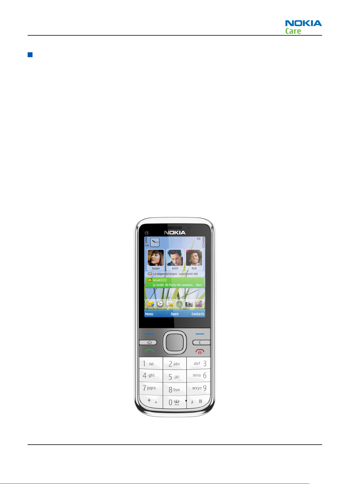
RM-645 is a HSDPA/HSUPA/WCDMA/GSM handportable phone with a monoblock form factor and A-GPS support.
It supports EGSM850/900/1800/1900 and WCDMA900/2100 bands, and GPRS/EGPRS, WCDMA/HSDPA/HSUPA
data bearers.
For WCDMA the maximum bit rate is up to 384 kbit/s for downlink and 384 kbit/s for uplink with simultaneous
CS speech or CS video (max. 64 kbit/s). The HSDPA peak is 10.2 Mbps and HSUPA peak is 2 Mbps (with limited
use cases).
For GPRS/EGPRS networks, RM-645 is a Class B EGPRS MSC 32 (5 Rx + 3 Tx, max sum 6), which means a maximum
upload speed of up to 298 kbit/s with EGPRS, and download speed of up to 178.8 kbit/s with GPRS. The device
also supports Dual Transfer Mode (DTM) for simultaneous voice and packet data connection in GSM/EDGE
networks; simple class A, multi slot class 11, (3 Rx + 2Tx), UL/DL=178.8/118.2 kbit/s.
RM-645 is an MMS (Multimedia Messaging Service) enabled multimedia device. The MMS implementation
follows the OMA MMS standard release 1.2. The device also supports Bluetooth 2.0 standard with stereo audio
profiles (A2DP & AVRCP).
RM-645 has a large 2.2’’ QVGA (320 x 240 pixels) display with 16.7 million colors, a 3.2 Megapixel main camera
that has an integrated LED flash and a digital zoom, and a 2nd VGA camera for video calls.
RM-645 uses Symbian 9.3 operating system, S60 (release 3.2) UI, and supports the full Web Browser for S60,
which brings desktop-like Web browsing experience to mobile devices.
RM-645 also supports MIDP Java 2.0, providing a good platform for compelling 3rd party applications.
Figure 1 View of RM-645
Issue 1 COMPANY CONFIDENTIAL Page 1 – 5
Copyright © 2010 Nokia. All rights reserved.
Page 18

Product features and sales package
Bearers and transport
•
GPRS/EGPRS Class B, Multi slot class 32
•
Dual Transfer Mode (DTM) class A, multi slot class 11
•
WCDMA DL 384kbit/s, UL 384 kbit/s
•
HSDPA up to 10.2Mbps, HSUPA 2Mbps
Connectivity
•
Assisted GPS (A-GPS)
•
Bluetooth 2.0 with stereo audio profiles (A2DP and AVRCP)
•
High Speed USB with micro USB connector
•
MicroSD memory card - support up to 16GB
•
3.5 mm AV connector
•
2.0 mm DC connector
•
USB charging
RM-645
General Information
Display
•
Large 2.2’’ QVGA (320 x 240 pixels) display with 16.7 million colors
Imaging and video
•
3.2 Megapixel EDOF (Extended Depth of Field) camera with a digital zoom, and an integrated LED flash
•
2nd VGA camera for video calls
•
Video streaming and sharing
•
Horizontal camera mode
•
Image capture, recording and zooming by navi key
•
Media player with MPEG-4, H. 263 and H.264 support
•
Image and video editors
Music
•
MP3 player supporting MP3, MP4, AAC, eAAC+ and WMA, progressive download from music player
•
Stereo FM Radio
Productivity
Context management
•
OMA DRM version 2.0
•
PIM (Calendar + Contacts + Active Notes) & Presence enhanced contacts
•
OTA provisioning & over the air SW update (FOTA)
•
Ovi Suite
•
Active Standby
•
Local/remote SyncML data sync
•
Web Browser (OSS), Java ™ MIDP 2.0, XHTML browsing over TCP/IP
Messaging
Page 1 – 6 COMPANY CONFIDENTIAL Issue 1
Copyright © 2010 Nokia. All rights reserved.
Page 19
RM-645
General Information
•
E-mail (SMTP, IMAP4, POP3)
•
SMS, MMS (OMA 1.2)
•
Audio Messaging (AMS)
Voice
•
Rich Calls: 2-way video conferencing (video call), video sharing
•
Voice commands, enhanced voice dialling (SIND)
•
Audio message reader for text messages and E-mail
Add-on software framework
•
Symbian OS
•
Nokia Series 60, 3rd edition, feature pack 3.2
•
Java: MIDP2.0
•
C++ and Java SDKs
Additional features
•
Tutorial
•
MP3 and AAC ringing tones, 64 polyphonic, 3D stereo ringing tones, video ringing tones
•
Flashlite 2.0
•
Vibrating alert
•
Speech codec support for AMR, EFR, FR
•
Nokia Online Share 4.3 (OVI Share)
•
Nokia Maps 3.0
Basic sales package
Basic sales package, there may be sales area variations.
•
Transceiver RM-645
•
Battery (BL-5CT/1050 mAh)
•
Travel charger (AC-8)
•
Stereo headset (WH-102)
•
Micro USB connectivity cable (CA-101)
•
MicroSD card 2GB (MU-37) with pre-loaded maps and OVI Suite 2.0
•
Short user guide
Product and module list
Module name Type code Notes
System/RF module PWB 3FT
UI flex 3FU
Issue 1 COMPANY CONFIDENTIAL Page 1 – 7
Copyright © 2010 Nokia. All rights reserved.
Page 20
Mobile enhancements
Table 1 Audio
Enhancement Type
Wired headsets HS-45/AD-44
WH-102 (inbox)
Bluetooth headsets BH-102
Bluetooth headsets (stereo) BH-103
BH-604
Table 2 Car
Enhancement Type
Car kit CK-15W
CK-300 (BT & plug-in)
RM-645
General Information
CK-7W
Holder CR-39
CR-82
CR-115
HH-17
Plug-in car handsfree HF-510
Table 3 Data
Enhancement Type
MicroSD card MU-22, 1 GB
MU-37, 2 GB (inbox)
MU-41, 4 GB
MU-43, 8 GB
MU-44, 16 GB
Connectivity cable CA-101D (inbox)
Table 4 Music
Enhancement Type
Bluetooth speakers MD-7W (BT & plug-in)
Mini speakers MD-9
Page 1 – 8 COMPANY CONFIDENTIAL Issue 1
Copyright © 2010 Nokia. All rights reserved.
Page 21
RM-645
General Information
Table 5 Messaging
Enhancement Type
Wireless keyboard SU-8W
Table 6 Power
Enhancement Type
Battery 1050 mAh Li-ion BL-5CT
Charger AC-6
AC-8 or AC-15 (inbox)
AC-10
Technical specifications
Transceiver general specifications
Unit Dimensions (L x W x T)
Transceiver with BL-5CT
1050 mAh Li-ion battery
back
(mm)
112.3 x 46 x 12.3 95 56.2
Weight (g)
Volume (cm3)
Main RF characteristics for GSM850/900/1800/1900 and WCDMA VIII (900) and WCDMA I (2100) phones
Parameter Unit
Cellular system GSM850, EGSM900, GSM1800/1900, WCDMA VIII
(900) and WCDMA I (2100)
Rx frequency band GSM850: 869 - 894 MHz
EGSM900: 925 - 960 MHz
GSM1800: 1805 - 1880 MHz
GSM1900: 1930 - 1990 MHz
WCDMA VIII (900): 925- 960 MHz
WCDMA I (2100): 2110 - 2170 MHz
Tx frequency band GSM850: 824 - 849 MHz
EGSM900: 880 - 915 MHz
GSM1800: 1710 - 1785 MHz
GSM1900: 1850 - 1910 MHz
WCDMA VIII (900): 880 - 915 MHz
WCDMA I (2100): 1920 - 1980 MHz
Issue 1 COMPANY CONFIDENTIAL Page 1 – 9
Copyright © 2010 Nokia. All rights reserved.
Page 22
General Information
Parameter Unit
Output power GSM850: +5 ...+33dBm/3.2mW ... 2W
GSM900: +5 … +33dBm/3.2mW … 2W
GSM1800: +0 … +30dBm/1.0mW … 1W
GSM1900: +0 … +30dBm/1.0mW … 1W
WCDMA VIII (900): -50 ... +24 dBm/0.01μW ...
251.2mW
WCDMA I (2100): -50 ... +24 dBm/0.01μW ...
251.2mW
EDGE output power EDGE850: +5 … +27dBm/3.2mW … 501mW
EDGE900: +5 … +27dBm/3.2mW … 501mW
EDGE1800: +0 … +26dBm/1.0mW … 400mW
EDGE1900:+0 … +26dBm/1.0mW … 400mW
Number of RF channels GSM850: 124
RM-645
GSM900: 174
GSM1800: 374
GSM1900: 299
WCDMA VIII (900): 152
WCDMA I (2100): 277
Channel spacing 200 kHz
Number of Tx power levels GSM850: 15
GSM900: 15
GSM1800: 16
GSM1900: 16
WCDMA VIII (900): 75
WCDMA I (2100): 75
Environmental conditions
Temperature conditions
Environmental condition Ambient temperature Notes
Normal operation
Reduced performance
Intermittent operation
Page 1 – 10 COMPANY CONFIDENTIAL Issue 1
-15oC...+55oC
-25oC...-15oC
+55oC...+70oC
-40oC...-15oC
+70oC...+85 oC
Copyright © 2010 Nokia. All rights reserved.
Specifications fulfilled
Operational for shorts periods
only
Operation not guaranteed but an
attempt to operate does not
damage the phone.
Page 23
RM-645
General Information
Environmental condition Ambient temperature Notes
No operation or storage
Charging allowed
Long term storage conditions
<-40oC...>+85oC
-25oC...+50oC
0oC...+85oC
No storage or operation: an
attempt may damage the phone.
Humidity
Relative humidity range is 5...95%.
The HW module is not protected against water. Condensed or splashed water might cause malfunction. Any
submersion of the phone will cause permanent damage. Long-term high humidity, with condensation, will
cause permanent damage because of corrosion.
Vibration
The module should withstand the following vibrations:
•
5 - 10 Hz; +10dB / octave
•
10 - 50 Hz; 5.58 m2 / s3 (0.0558 g2/ Hz)
•
50 - 300 Hz; - 10 dB / octave
ESD strength
Conducted discharge is 8 kV (>10 discharges) and air contact 15 kV ( >10 discharges ).
The standard for electrostatic discharge is IEC 61000-4-2, and this device fulfils level 4 requirements.
RoHS
This device uses RoHS compliant components and lead-free soldering process.
Issue 1 COMPANY CONFIDENTIAL Page 1 – 11
Copyright © 2010 Nokia. All rights reserved.
Page 24

RM-645
General Information
(This page left intentionally blank.)
Page 1 – 12 COMPANY CONFIDENTIAL Issue 1
Copyright © 2010 Nokia. All rights reserved.
Page 25

Nokia Customer Care
2 — Service Tools and Service
Concepts
Issue 1 COMPANY CONFIDENTIAL Page 2 – 1
Copyright © 2010 Nokia. All rights reserved.
Page 26

RM-645
Service Tools and Service Concepts
(This page left intentionally blank.)
Page 2 – 2 COMPANY CONFIDENTIAL Issue 1
Copyright © 2010 Nokia. All rights reserved.
Page 27

RM-645
Service Tools and Service Concepts
Table of Contents
Service tools........................................................................................................................................................... 2–5
Product specific tools....................................................................................................................................... 2–5
FS-150........................................................................................................................................................... 2–5
MJ-276 .......................................................................................................................................................... 2–5
SA-131 .......................................................................................................................................................... 2–6
General tools..................................................................................................................................................... 2–6
AC-35............................................................................................................................................................. 2–6
ACF-8............................................................................................................................................................. 2–6
CU-4............................................................................................................................................................... 2–7
FLS-5 ............................................................................................................................................................. 2–8
FPS-21........................................................................................................................................................... 2–8
JXS-1.............................................................................................................................................................. 2–9
PK-1............................................................................................................................................................... 2–9
RJ-230 ........................................................................................................................................................... 2–9
SB-6............................................................................................................................................................... 2–9
SRT-6............................................................................................................................................................. 2–9
SS-46.......................................................................................................................................................... 2–10
SS-62.......................................................................................................................................................... 2–10
SS-88.......................................................................................................................................................... 2–10
SS-93.......................................................................................................................................................... 2–10
SX-4............................................................................................................................................................ 2–10
Cables.............................................................................................................................................................. 2–10
CA-101 ....................................................................................................................................................... 2–11
CA-128RS ................................................................................................................................................... 2–11
CA-31D ....................................................................................................................................................... 2–11
CA-89DS ..................................................................................................................................................... 2–12
DAU-9S....................................................................................................................................................... 2–12
PCS-1.......................................................................................................................................................... 2–12
XRS-6.......................................................................................................................................................... 2–13
Service concepts ................................................................................................................................................. 2–13
POS (Point of Sale) flash concept ................................................................................................................. 2–13
Flash concept with FPS-21............................................................................................................................ 2–14
CU-4 flash concept with FPS-21.................................................................................................................... 2–15
Module jig service concept........................................................................................................................... 2–16
BB/RF tuning concept with module jig ....................................................................................................... 2–17
Bluetooth testing concept with SB-6 .......................................................................................................... 2–18
GPS testing concept with GPS RF coupler.................................................................................................... 2–19
List of Figures
Figure 2 POS flash concept ................................................................................................................................ 2–13
Figure 3 Basic flash concept with FPS-21......................................................................................................... 2–14
Figure 4 CU-4 flash concept with FPS-21.......................................................................................................... 2–15
Figure 5 Module jig service concept ................................................................................................................. 2–16
Figure 6 Service concept for RF testing and RF/BB tuning ............................................................................. 2–18
Figure 7 RF testing concept with RF coupler ................................................................................................... 2–19
Issue 1 COMPANY CONFIDENTIAL Page 2 – 3
Copyright © 2010 Nokia. All rights reserved.
Page 28

RM-645
Service Tools and Service Concepts
(This page left intentionally blank.)
Page 2 – 4 COMPANY CONFIDENTIAL Issue 1
Copyright © 2010 Nokia. All rights reserved.
Page 29
RM-645
Service Tools and Service Concepts
Service tools
Product specific tools
The table below gives a short overview of service devices that can be used for testing, error analysis, and
repair of product RM-645. For the correct use of the service devices, and the best effort of workbench setup,
please refer to various concepts.
FS-150 Flash adapter For flashing (also dead phones) with SS-46. CU-4 supported.
MJ-276 Module jig MJ-276 is meant for component level troubleshooting.
The jig includes an RF interface for GSM, WCDMA and Bluetooth. In
addition, it has the following features:
•
Provides mechanical interface with the engine module
•
Provides galvanic connection to all needed test pads in module
•
Multiplexing between USB and FBUS media, controlled by Vusb
•
MMC interface
•
Duplicated SIM connector
•
Connector for control unit
•
Access for AV- and USB connectors
•
CA-128RS cable is used together with this jig for RF testing
•
Attenuation values for galvanic RF connection MJ-276
Band Default f/
MHz RX
GSM 850 881.6 18.0 836.6 18.0
GSM 900 942.4 18.0 897.4 18.0
Att. RX Default f/
MHz TX
Att. TX
GSM 1800 1842.8 24.0 1747.8 24.0
GSM 1900 1960.0 24.0 1880.0 24.0
WCDMA I 2140.0 17.0 1950.0 17.0
WCDMA VIII 942.6 18.0 897.6 18.0
Issue 1 COMPANY CONFIDENTIAL Page 2 – 5
Copyright © 2010 Nokia. All rights reserved.
Page 30
RM-645
Service Tools and Service Concepts
SA-131 RF coupler SA-131 is a generic device for GPS testing. It is used together with
SS-62.
General tools
The table below gives a short overview of service devices that can be used for testing, error analysis, and
repair of product RM-645. For the correct use of the service devices, and the best effort of workbench setup,
please refer to various concepts.
AC-35 Power supply Universal power supply for FPS-21; included in the FPS-21 sales
package.
Input 100V…230V 50Hz…60Hz, output voltage of 12 V and output
current up to 3 A.
ACF-8 Universal power
supply
The ACF-8 universal power supply is used to power FLS-5.
Page 2 – 6 COMPANY CONFIDENTIAL Issue 1
Copyright © 2010 Nokia. All rights reserved.
Page 31

RM-645
Service Tools and Service Concepts
CU-4 Control unit CU-4 is a general service tool used with a module jig and/or a flash
adapter. It requires an external 12 V power supply.
The unit has the following features:
•
software controlled via USB
•
EM calibration function
•
Forwards FBUS/Flashbus traffic to/from terminal
•
Forwards USB traffic to/from terminal
•
software controlled BSI values
•
regulated VBATT voltage
•
2 x USB2.0 connector (Hub)
•
FBUS and USB connections supported
When using CU-4, note the special order of connecting cables and
other service equipment:
Instructions
1 Connect a service tool (jig, flash adapter) to CU-4.
2 Connect CU-4 to your PC with a USB cable.
3 Connect supply voltage (12 V)
4 Connect an FBUS cable (if necessary).
5 Start Phoenix service software.
Note: Phoenix enables CU-4 regulators via USB when it is
started.
Reconnecting the power supply requires a Phoenix restart.
Issue 1 COMPANY CONFIDENTIAL Page 2 – 7
Copyright © 2010 Nokia. All rights reserved.
Page 32

RM-645
Service Tools and Service Concepts
FLS-5 Flash device FLS-5 is a dongle and flash device incorporated into one package,
developed specifically for POS use.
Note: FLS-5 can be used as an alternative to PK-1.
FPS-21 Flash prommer
FPS-21 sales package:
•
FPS-21 prommer
•
AC-35 power supply
•
CA-31D USB cable
FPS-21 interfaces:
Front
•
Service cable connector
Provides Flashbus, USB and VBAT connections to a mobile device.
•
SmartCard socket
A SmartCard is needed to allow DCT-4 generation mobile device
programming.
Rear
•
DC power input
For connecting the external power supply (AC-35).
•
Two USB A type ports (USB1/USB3)
Can be used, for example, for connecting external storage memory
devices or mobile devices
•
One USB B type device connector (USB2)
For connecting a PC.
•
Phone connector
Service cable connection for connecting Flashbus/FLA.
•
Ethernet RJ45 type socket (LAN)
For connecting the FPS-21 to LAN.
Inside
•
Four SD card memory slots
For internal storage memory.
Note: In order to access the SD memory card slots inside
FPS-21, the prommer needs to be opened by removing the
front panel, rear panel and heatsink from the prommer body.
Page 2 – 8 COMPANY CONFIDENTIAL Issue 1
Copyright © 2010 Nokia. All rights reserved.
Page 33

RM-645
Service Tools and Service Concepts
JXS-1 RF shield box Because the WCDMA network disturbs the RX side testing of the WCDMA
phone and the Tx signal of the WCDMA phone can severely disturb the
WCDMA network, a shield box is needed in all testing, tuning and fault
finding which requires WCDMA RF signal.
The shield box is not an active device, it contains only passive filtering
components for RF attenuation.
PK-1 Software protection
key
PK-1 is a hardware protection key with a USB interface. It has the same
functionality as the PKD-1 series dongle.
PK-1 is meant for use with a PC that does not have a series interface.
To use this USB dongle for security service functions please register
the dongle in the same way as the PKD-1 series dongle.
RJ-230 Soldering jig
RJ-230 is a soldering jig used for soldering and as a rework jig for the
engine module.
SB-6 Bluetooth test and
interface box (sales
package)
The SB-6 test box is a generic service device used to perform Bluetooth
bit error rate (BER) testing, and establishing cordless FBUS connection
via Bluetooth. An ACP-8x charger is needed for BER testing and an
AXS-4 cable in case of cordless interface usage testing .
Sales package includes:
•
SB-6 test box
•
Installation and warranty information
SRT-6 Opening tool SRT-6 is used to open phone covers.
Note: The SRT-6 is included in the Nokia Standard Toolkit.
Issue 1 COMPANY CONFIDENTIAL Page 2 – 9
Copyright © 2010 Nokia. All rights reserved.
Page 34

RM-645
Service Tools and Service Concepts
SS-46 Interface adapter SS-46 acts as an interface adapter between the flash adapter and
FPS-21.
SS-62 Generic flash adapter
base for BB5
•
generic base for flash adapters and couplers
•
SS-62 equipped with a clip interlock system
•
provides standardised interface towards Control Unit
•
multiplexing between USB and FBUS media, controlled by VUSB
SS-88 Camera removal tool The camera removal tool SS-88 is used to remove/attach the camera
module from/to the socket.
SS-93 Opening tool SS-93 is used for opening JAE connectors.
Note: The SS-93 is included in Nokia Standard Toolkit.
SX-4 Smart card SX-4 is a BB5 security device used to protect critical features in tuning
and testing.
SX-4 is also needed together with FPS-21 when DCT-4 phones are
flashed.
Cables
The table below gives a short overview of service devices that can be used for testing, error analysis, and
repair of product RM-645. For the correct use of the service devices, and the best effort of workbench setup,
please refer to various concepts.
Page 2 – 10 COMPANY CONFIDENTIAL Issue 1
Copyright © 2010 Nokia. All rights reserved.
Page 35

RM-645
Service Tools and Service Concepts
CA-101 Micro USB cable The CA-101 is a USB-to-microUSB data cable that allows connections
between the PC and the phone.
CA-128RS RF tuning cable Product-specific adapter cable for RF tuning.
CA-31D USB cable The CA-31D USB cable is used to connect FPS-21 to a PC. It is included
in the FPS-21 sales package.
Issue 1 COMPANY CONFIDENTIAL Page 2 – 11
Copyright © 2010 Nokia. All rights reserved.
Page 36

RM-645
Service Tools and Service Concepts
CA-89DS Cable Provides VBAT and Flashbus connections to mobile device
programming adapters.
DAU-9S MBUS cable The MBUS cable DAU-9S has a modular connector and is used, for
example, between the PC's serial port and module jigs, flash adapters
or docking station adapters.
Note: Docking station adapters valid for DCT4 products.
PCS-1 Power cable The PCS-1 power cable (DC) is used with a docking station, a module
jig or a control unit to supply a controlled voltage.
Page 2 – 12 COMPANY CONFIDENTIAL Issue 1
Copyright © 2010 Nokia. All rights reserved.
Page 37

RM-645
Service Tools and Service Concepts
Service concepts
POS (Point of Sale) flash concept
XRS-6 RF cable The RF cable is used to connect, for example, a module repair jig to
the RF measurement equipment.
SMA to N-Connector approximately 610 mm.
Attenuation for:
•
GSM850/900: 0.3+-0.1 dB
•
GSM1800/1900: 0.5+-0.1 dB
•
WCDMA2100/WLAN: 0.6+-0.1 dB
•
WCDMA900: 0.3+-0.1 dB
Figure 2 POS flash concept
Type Description
Product specific tools
BL-5CT Battery
Other tools
FLS-5 POS flash dongle
PC with Phoenix service software
Issue 1 COMPANY CONFIDENTIAL Page 2 – 13
Copyright © 2010 Nokia. All rights reserved.
Page 38

Type Description
Cables
CA-101 Micro USB cable
Flash concept with FPS-21
RM-645
Service Tools and Service Concepts
Figure 3 Basic flash concept with FPS-21
Type Description
Product specific devices
FS-150 Flash adapter
Other devices
FPS-21 Flash prommer box
AC-35 Power supply
PK-1 SW security device
SS-46 Interface adapter
PC with Phoenix service software
Cables
CA-89DS Service cable
Page 2 – 14 COMPANY CONFIDENTIAL Issue 1
Copyright © 2010 Nokia. All rights reserved.
Page 39

RM-645
Service Tools and Service Concepts
Type Description
USB cable
CU-4 flash concept with FPS-21
Figure 4 CU-4 flash concept with FPS-21
Type Description
Product specific devices
FS-150 Flash adapter
Other devices
CU-4 Control unit
FPS-21 Flash prommer box
AC-35 Power supply
PK-1 SW security device
SS-62 Flash adapter base
SX-4 Smart card (for DCT-4 generation mobile device programming)
PC with Phoenix service software
Cables
Issue 1 COMPANY CONFIDENTIAL Page 2 – 15
Copyright © 2010 Nokia. All rights reserved.
Page 40

Type Description
PCS-1 Power cable
CA-89DS Service cable
Standard USB cable
USB cable
Module jig service concept
RM-645
Service Tools and Service Concepts
Figure 5 Module jig service concept
Type Description
Phone specific devices
MJ-276 Module jig
Other devices
CU-4 Control unit
FPS-21 Flash prommer box
PK-1 SW security device
SX-4 Smart card
PC with VPOS and Phoenix service software
Measurement equipment
Cables
CA-89DS Service cable
Page 2 – 16 COMPANY CONFIDENTIAL Issue 1
Copyright © 2010 Nokia. All rights reserved.
Page 41

RM-645
Service Tools and Service Concepts
Type Description
PCS-1 DC power cable
XRS-6 RF cable
USB cable
GPIB control cable
BB/RF tuning concept with module jig
Type Description
Product specific tools
MJ-276 Module jig
Other tools
CU-4 Control unit
PK-1 SW security device
SX-4 Smart card
PC with Phoenix service software
Smart card reader
Cables
DAU-9S MBUS cable
PCS-1 Power cable
Issue 1 COMPANY CONFIDENTIAL Page 2 – 17
Copyright © 2010 Nokia. All rights reserved.
Page 42

Type Description
XRS-6 RF cable
USB cable
Bluetooth testing concept with SB-6
RM-645
Service Tools and Service Concepts
Figure 6 Service concept for RF testing and RF/BB tuning
Type Description
Product specific devices
FS-150 Flash adapter
Other devices
CU-4 Control unit
SS-62 Flash adapter base
PK-1 SW security device
SX-4 Smart card
SB-6 Bluetooth test and interface box
Smart card reader
PC with Phoenix service software
Cables
DAU-9S MBUS cable
PCS-1 DC power cable
Page 2 – 18 COMPANY CONFIDENTIAL Issue 1
Copyright © 2010 Nokia. All rights reserved.
Page 43

RM-645
Service Tools and Service Concepts
Type Description
USB cable
GPS testing concept with GPS RF coupler
Figure 7 RF testing concept with RF coupler
Type Description
Product specific devices
FS-150 Flash adapter
SA-131 GPS RF coupler
Other devices
CU-4 Control unit
SX-4 Smart card
JXS-1 RF shield box
PK-1 SW security device
SS-62 Flash adapter base
Smart card reader
Measurement equipment
PC with Phoenix service software
Cables
Issue 1 COMPANY CONFIDENTIAL Page 2 – 19
Copyright © 2010 Nokia. All rights reserved.
Page 44

Type Description
CA-128RS RF service cable (product-specific adapter cable)
PCS-1 Power cable
DAU-9S MBUS cable
XRS-6 RF cable
20dB attenuator
Interface cable
USB cable
RM-645
Service Tools and Service Concepts
Page 2 – 20 COMPANY CONFIDENTIAL Issue 1
Copyright © 2010 Nokia. All rights reserved.
Page 45

Nokia Customer Care
3 — BB Troubleshooting and
Manual Tuning Guide
Issue 1 COMPANY CONFIDENTIAL Page 3 – 1
Copyright © 2010 Nokia. All rights reserved.
Page 46

RM-645
BB Troubleshooting and Manual Tuning Guide
(This page left intentionally blank.)
Page 3 – 2 COMPANY CONFIDENTIAL Issue 1
Copyright © 2010 Nokia. All rights reserved.
Page 47

RM-645
BB Troubleshooting and Manual Tuning Guide
Table of Contents
Baseband self tests in Phoenix ............................................................................................................................ 3–5
Power and charging troubleshooting................................................................................................................. 3–7
Dead or jammed device troubleshooting...................................................................................................... 3–7
Power key troubleshooting............................................................................................................................. 3–9
General voltage checking troubleshooting .................................................................................................. 3–9
General power checking............................................................................................................................... 3–12
Charging troubleshooting ............................................................................................................................ 3–13
USB charging troubleshooting..................................................................................................................... 3–13
Battery current measuring fault troubleshooting ..................................................................................... 3–15
Clocking troubleshooting ............................................................................................................................. 3–16
Interface troubleshooting ................................................................................................................................. 3–17
Flash programming fault troubleshooting................................................................................................. 3–17
SIM card troubleshooting ............................................................................................................................. 3–20
MicroSD card troubleshooting...................................................................................................................... 3–22
USB data interface troubleshooting............................................................................................................ 3–23
User interface troubleshooting......................................................................................................................... 3–24
Keyboard and side keys troubleshooting ................................................................................................... 3–24
Keyboard LEDs troubleshooting................................................................................................................... 3–26
Display module troubleshooting................................................................................................................. 3–27
General instructions for display troubleshooting................................................................................. 3–27
Display fault troubleshooting ................................................................................................................. 3–29
Display backlight troubleshooting ......................................................................................................... 3–29
Audio troubleshooting....................................................................................................................................... 3–30
Audio troubleshooting test instructions..................................................................................................... 3–30
Internal earpiece troubleshooting .............................................................................................................. 3–34
Internal microphone troubleshooting........................................................................................................ 3–35
Internal handsfree (IHF) troubleshooting................................................................................................... 3–36
External earpiece troubleshooting.............................................................................................................. 3–36
External microphone troubleshooting........................................................................................................ 3–38
Acoustics troubleshooting............................................................................................................................ 3–39
Introduction to acoustics troubleshooting ........................................................................................... 3–39
Earpiece troubleshooting........................................................................................................................ 3–40
IHF troubleshooting................................................................................................................................. 3–41
Microphone troubleshooting .................................................................................................................. 3–42
Vibra troubleshooting................................................................................................................................... 3–43
GPS troubleshooting .......................................................................................................................................... 3–43
GPS antenna................................................................................................................................................... 3–43
GPS layout and basic test points.................................................................................................................. 3–45
GPS settings for Phoenix............................................................................................................................... 3–45
GPS control................................................................................................................................................ 3–45
Oscillator test............................................................................................................................................ 3–47
Receiver self test ...................................................................................................................................... 3–48
CW Test...................................................................................................................................................... 3–49
Quick Test window................................................................................................................................... 3–50
GPS failure troubleshooting......................................................................................................................... 3–51
GPS basic checks troubleshooting ............................................................................................................... 3–52
Bluetooth and FM radio troubleshooting ........................................................................................................ 3–53
Bluetooth and FM radio introduction.......................................................................................................... 3–53
Bluetooth and FM radio component placement ........................................................................................ 3–54
Bluetooth and FM Radio Self Tests .............................................................................................................. 3–55
Issue 1 COMPANY CONFIDENTIAL Page 3 – 3
Copyright © 2010 Nokia. All rights reserved.
Page 48

RM-645
BB Troubleshooting and Manual Tuning Guide
Bluetooth BER test......................................................................................................................................... 3–56
Bluetooth and FM radio module troubleshooting ..................................................................................... 3–57
Baseband manual tuning guide........................................................................................................................ 3–58
Certificate restoring for BB5 products......................................................................................................... 3–58
Energy management calibration................................................................................................................. 3–63
List of Tables
Table 7 Display module troubleshooting cases............................................................................................... 3–27
Table 8 Pixel defects .......................................................................................................................................... 3–27
Table 9 Calibration value limits ........................................................................................................................ 3–63
List of Figures
Figure 8 Flashing pic 1. Take single trig measurement for the rise of the BSI signal................................. 3–18
Figure 9 Flashing pic 2. Take single trig measurement for the rise of the BSI signal................................. 3–19
Figure 10 AV_IN – HP_OUT, single-ended loop measurement........................................................................ 3–32
Figure 11 AV_IN – IHF_L_OUT, single-ended loop measurement without filter............................................ 3–33
Figure 12 AV_IN – AV_L _OUT, single-ended loop measurement.................................................................... 3–33
Figure 13 GPS antenna....................................................................................................................................... 3–44
Figure 14 GPS layout and basic test points...................................................................................................... 3–45
Figure 15 GPS Control dialog box...................................................................................................................... 3–46
Figure 16 Simple Tests – Oscillator Test & Receiver Self Test ........................................................................ 3–47
Figure 17 Simple Tests – Oscillator Test........................................................................................................... 3–48
Figure 18 Simple Tests – Receiver Self Test ..................................................................................................... 3–49
Figure 19 CW Test window................................................................................................................................ 3–50
Figure 20 GPS Quick Test window for GPS troubleshooting .......................................................................... 3–51
Figure 21 Key component placement for BTHFMRDS2.2D .............................................................................. 3–55
Figure 22 BT antenna......................................................................................................................................... 3–55
Page 3 – 4 COMPANY CONFIDENTIAL Issue 1
Copyright © 2010 Nokia. All rights reserved.
Page 49

RM-645
BB Troubleshooting and Manual Tuning Guide
Baseband self tests in Phoenix
Context
Always start the troubleshooting procedure by running the Phoenix self tests. If a test fails, please follow the
diagram below.
If the phone is dead and you cannot perform the self tests, go to
Dead or jammed device troubleshooting.
Issue 1 COMPANY CONFIDENTIAL Page 3 – 5
Copyright © 2010 Nokia. All rights reserved.
Page 50

Troubleshooting flow
RM-645
BB Troubleshooting and Manual Tuning Guide
Page 3 – 6 COMPANY CONFIDENTIAL Issue 1
Copyright © 2010 Nokia. All rights reserved.
Page 51

RM-645
BB Troubleshooting and Manual Tuning Guide
Power and charging troubleshooting
Dead or jammed device troubleshooting
Troubleshooting flow - Page 1 of 2
Issue 1 COMPANY CONFIDENTIAL Page 3 – 7
Copyright © 2010 Nokia. All rights reserved.
Page 52

Troubleshooting flow - Page 2 of 2
RM-645
BB Troubleshooting and Manual Tuning Guide
Page 3 – 8 COMPANY CONFIDENTIAL Issue 1
Copyright © 2010 Nokia. All rights reserved.
Page 53

RM-645
BB Troubleshooting and Manual Tuning Guide
Power key troubleshooting
Troubleshooting flow
Issue 1 COMPANY CONFIDENTIAL Page 3 – 9
Copyright © 2010 Nokia. All rights reserved.
Page 54

General voltage checking troubleshooting
Troubleshooting flow - Page 1 of 2
RM-645
BB Troubleshooting and Manual Tuning Guide
Page 3 – 10 COMPANY CONFIDENTIAL Issue 1
Copyright © 2010 Nokia. All rights reserved.
Page 55

RM-645
BB Troubleshooting and Manual Tuning Guide
Troubleshooting flow - Page 2 of 2
Issue 1 COMPANY CONFIDENTIAL Page 3 – 11
Copyright © 2010 Nokia. All rights reserved.
Page 56

General power checking
Check the following voltages:
RM-645
BB Troubleshooting and Manual Tuning Guide
Signal
Rename
VIO Gazoo ON ON 1.8 Memory, I/Os,
VSIM Gazoo ON ON 1.8/3.0 SIM card
VAUX1 Gazoo ON ON 2.8 Display
VMEM Gazoo OFF OFF 2.9 MicroSD Disabled in
VDIGMIC Gazoo OFF OFF 1.8 Audio
Regulator Sleep Idle Nominal
voltage
Main user Notes
display
sleep
Page 3 – 12 COMPANY CONFIDENTIAL Issue 1
Copyright © 2010 Nokia. All rights reserved.
Page 57

RM-645
BB Troubleshooting and Manual Tuning Guide
Charging troubleshooting
Troubleshooting flow
Issue 1 COMPANY CONFIDENTIAL Page 3 – 13
Copyright © 2010 Nokia. All rights reserved.
Page 58

USB charging troubleshooting
Troubleshooting flow
RM-645
BB Troubleshooting and Manual Tuning Guide
Page 3 – 14 COMPANY CONFIDENTIAL Issue 1
Copyright © 2010 Nokia. All rights reserved.
Page 59

RM-645
BB Troubleshooting and Manual Tuning Guide
Battery current measuring fault troubleshooting
Troubleshooting flow
Issue 1 COMPANY CONFIDENTIAL Page 3 – 15
Copyright © 2010 Nokia. All rights reserved.
Page 60

Clocking troubleshooting
Troubleshooting flow
RM-645
BB Troubleshooting and Manual Tuning Guide
Page 3 – 16 COMPANY CONFIDENTIAL Issue 1
Copyright © 2010 Nokia. All rights reserved.
Page 61

RM-645
BB Troubleshooting and Manual Tuning Guide
Interface troubleshooting
Flash programming fault troubleshooting
Troubleshooting flow - Page 1 of 2
Issue 1 COMPANY CONFIDENTIAL Page 3 – 17
Copyright © 2010 Nokia. All rights reserved.
Page 62

Troubleshooting flow - Page 2 of 2
RM-645
BB Troubleshooting and Manual Tuning Guide
Figure 8 Flashing pic 1. Take single trig measurement for the rise of the BSI signal
Page 3 – 18 COMPANY CONFIDENTIAL Issue 1
Copyright © 2010 Nokia. All rights reserved.
Page 63

RM-645
BB Troubleshooting and Manual Tuning Guide
Figure 9 Flashing pic 2. Take single trig measurement for the rise of the BSI signal
Issue 1 COMPANY CONFIDENTIAL Page 3 – 19
Copyright © 2010 Nokia. All rights reserved.
Page 64

SIM card troubleshooting
Troubleshooting flow
RM-645
BB Troubleshooting and Manual Tuning Guide
Page 3 – 20 COMPANY CONFIDENTIAL Issue 1
Copyright © 2010 Nokia. All rights reserved.
Page 65

RM-645
BB Troubleshooting and Manual Tuning Guide
Issue 1 COMPANY CONFIDENTIAL Page 3 – 21
Copyright © 2010 Nokia. All rights reserved.
Page 66

MicroSD card troubleshooting
Troubleshooting flow
RM-645
BB Troubleshooting and Manual Tuning Guide
Page 3 – 22 COMPANY CONFIDENTIAL Issue 1
Copyright © 2010 Nokia. All rights reserved.
Page 67

RM-645
BB Troubleshooting and Manual Tuning Guide
USB data interface troubleshooting
Troubleshooting flow - Page 1 of 2
Issue 1 COMPANY CONFIDENTIAL Page 3 – 23
Copyright © 2010 Nokia. All rights reserved.
Page 68

Troubleshooting flow - Page 2 of 2
RM-645
BB Troubleshooting and Manual Tuning Guide
User interface troubleshooting
Keyboard and side keys troubleshooting
Context
There are two possible failure modes in the keyboard module:
•
One or more keys are stuck, so that the key does not react when a keydome or a side key is pressed. This
kind of failure is caused by mechanical reasons (dirt, rust, mechanical damage, etc.)
Page 3 – 24 COMPANY CONFIDENTIAL Issue 1
Copyright © 2010 Nokia. All rights reserved.
Page 69

RM-645
BB Troubleshooting and Manual Tuning Guide
•
Malfunction of several keys at the same time. This happens when one or more rows or columns in the key
matrix are failing (shortcut or open connection).
If the failure mode is not clear, start with the Keyboard test in Phoenix.
In this phone the keyboard is connected to D2800 I/O pins.
Troubleshooting flow
Issue 1 COMPANY CONFIDENTIAL Page 3 – 25
Copyright © 2010 Nokia. All rights reserved.
Page 70

Keyboard LEDs troubleshooting
Troubleshooting flow
RM-645
BB Troubleshooting and Manual Tuning Guide
Page 3 – 26 COMPANY CONFIDENTIAL Issue 1
Copyright © 2010 Nokia. All rights reserved.
Page 71

RM-645
BB Troubleshooting and Manual Tuning Guide
Display module troubleshooting
General instructions for display troubleshooting
Context
•
The display is in a normal mode when the phone is in active use.
•
The operating modes of the display can be controlled with the help of
Table 7 Display module troubleshooting cases
Display blank There is no image on the display. The display looks
the same when the phone is on as it does when the
phone is off. The backlight can be on in some cases.
Image on the display not correct Image on the display can be corrupted or a part of
the image can be missing.
•
If a part of the image is missing, change the
display module.
•
If the image is otherwise corrupted, follow the
display fault troubleshooting flowchart.
Phoenix
.
Backlight dim or not working at all Backlight LED components are inside the display
module. Backlight failure can also be in the
connector or in the backlight power source in the
main engine of the phone.
This means that in case the display is working
(image OK), the backlight is faulty.
Visual defects (pixel) Pixel defects can be checked by controlling the
display with Phoenix. Use both colours, black and
white, on a full screen.
The display may have some random pixel defects
that are acceptable for this type of display. The
criteria when pixel defects are regarded as a display
failure, resulting in a replacement of the display, are
presented the following table.
Table 8 Pixel defects
Item White dot defect Black dot
defect
1 Defect counts R G B White Dot
Total
1 1
Total
1 1 1 1
2 Combined
defect counts
Issue 1 COMPANY CONFIDENTIAL Page 3 – 27
Not allowed.
Two single dot defects that are within 5 mm of each other should be
interpreted as combined dot defect.
Copyright © 2010 Nokia. All rights reserved.
Page 72

BB Troubleshooting and Manual Tuning Guide
Steps
1. Verify with a working display that the fault is not on the display module itself.
The display module cannot be repaired.
2. Check that the cellular engine is working normally.
i To check the functionality, connect the phone to a docking station.
ii Start
iii Read the phone information to check that also the application engine is functioning normally (you
3. Proceed to the display fault troubleshooting flowchart.
Use the Display Test tool in
Phoenix
should be able to read the APE ID).
service software.
Phoenix
to find the detailed fault mode.
RM-645
Page 3 – 28 COMPANY CONFIDENTIAL Issue 1
Copyright © 2010 Nokia. All rights reserved.
Page 73

RM-645
BB Troubleshooting and Manual Tuning Guide
Display fault troubleshooting
Troubleshooting flow
Issue 1 COMPANY CONFIDENTIAL Page 3 – 29
Copyright © 2010 Nokia. All rights reserved.
Page 74

Display backlight troubleshooting
Troubleshooting flow
RM-645
BB Troubleshooting and Manual Tuning Guide
Audio troubleshooting
Audio troubleshooting test instructions
External earpiece, internal earpiece and internal handsfree outputs can be measured either with a singleended or a differential probe.
When measuring with a single-ended probe each output is measured against the ground.
The input signal for each loop test is single-ended.
Page 3 – 30 COMPANY CONFIDENTIAL Issue 1
Copyright © 2010 Nokia. All rights reserved.
Page 75

RM-645
BB Troubleshooting and Manual Tuning Guide
Required equipment
The following equipment is needed for the tests:
•
Oscilloscope
•
Function generator (sine waveform)
•
Phoenix service software
•
Battery voltage 3.7V
Test procedure
Audio can be tested using the Phoenix audio routings option. Three different audio loop paths are used in
the tests:
•
AV mic to AV ear
•
AV mic to HP ear
•
Ext microphone in Int handsfree out
Note: The internal uplink microphones can be tested using the Phoenix self test "ST-DIGIMIC-TEST".
If the test result is PASS, the uplink microphones are electrically OK. For more thorough testing, see
section
Each audio loop sets routing from the specified input to the specified output enables a quick in-out test. Loop
path gains are fixed and they cannot be changed using Phoenix. Correct pins and signals for each test are
presented in a table in the following section.
Internal microphone troubleshooting
.
Phoenix audio loop tests and test results
The results presented in this table apply when no accessory is connected and battery voltage is set to 3.7V.
Earpiece, internal microphone and speakers are in place during measurement. Applying a headset accessory
during measurement causes a significant drop in measured quantities.
The gain values presented in the table apply for a differential output vs. single-ended/differential input.
Loop test Input
terminal
AV mic to AV ear HS_MIC
and GND
AV mic to HP ear HS_MIC
and GND
Output
terminal
HS_EAR_R and
GND
HS_EAR_L and
GND
B2101 pad1
and GND
B2101 pad2
and GND
Path gain
[dB] (fixed)
+21.3 100 584 0
+18.2 100 407 1.5
Input voltage,
1 kHz sine
[mVp-p]
Single-ended
output
voltage [mVp-
p]
Output
DC level
[V]
Issue 1 COMPANY CONFIDENTIAL Page 3 – 31
Copyright © 2010 Nokia. All rights reserved.
Page 76

RM-645
BB Troubleshooting and Manual Tuning Guide
Loop test Input
terminal
Ext microphone
in Int handsfree
out
HS_MIC
and GND
Measurement data
Output
terminal
B2102 pad1
and GND
B2102 pad2
and GND
B2103 pad1
and GND
B2103 pad2
and GND
Path gain
[dB] (fixed)
+3.6 with
lowpass
filter
Input voltage,
1 kHz sine
[mVp-p]
1000 758 with
Single-ended
output
voltage [mVp-
lowpass filter
See the
Measurement
data
graphics
below
Output
DC level
[V]
p]
NA
Figure 10 AV_IN – HP_OUT, single-ended loop measurement
Page 3 – 32 COMPANY CONFIDENTIAL Issue 1
Copyright © 2010 Nokia. All rights reserved.
Page 77

RM-645
BB Troubleshooting and Manual Tuning Guide
Figure 11 AV_IN – IHF_L_OUT, single-ended loop measurement without filter
Figure 12 AV_IN – AV_L _OUT, single-ended loop measurement
Issue 1 COMPANY CONFIDENTIAL Page 3 – 33
Copyright © 2010 Nokia. All rights reserved.
Page 78

Internal earpiece troubleshooting
Troubleshooting flow
RM-645
BB Troubleshooting and Manual Tuning Guide
Page 3 – 34 COMPANY CONFIDENTIAL Issue 1
Copyright © 2010 Nokia. All rights reserved.
Page 79

RM-645
BB Troubleshooting and Manual Tuning Guide
Internal microphone troubleshooting
Troubleshooting flow
Issue 1 COMPANY CONFIDENTIAL Page 3 – 35
Copyright © 2010 Nokia. All rights reserved.
Page 80

Internal handsfree (IHF) troubleshooting
Troubleshooting flow
RM-645
BB Troubleshooting and Manual Tuning Guide
Page 3 – 36 COMPANY CONFIDENTIAL Issue 1
Copyright © 2010 Nokia. All rights reserved.
Page 81

RM-645
BB Troubleshooting and Manual Tuning Guide
External earpiece troubleshooting
Troubleshooting flow
Issue 1 COMPANY CONFIDENTIAL Page 3 – 37
Copyright © 2010 Nokia. All rights reserved.
Page 82

External microphone troubleshooting
Troubleshooting flow
RM-645
BB Troubleshooting and Manual Tuning Guide
Page 3 – 38 COMPANY CONFIDENTIAL Issue 1
Copyright © 2010 Nokia. All rights reserved.
Page 83

RM-645
BB Troubleshooting and Manual Tuning Guide
Acoustics troubleshooting
Introduction to acoustics troubleshooting
Acoustics design ensures that the sound is detected correctly with a microphone and properly radiated to
the outside of the device by the speaker. The acoustics of the phone include three basic systems: earpiece,
stereo integrated handsfree (IHF) and digital microphone.
The sound reproduced from the earpiece readiates through a single hole on the front cover (A-cover). The
sound reproduced from the 2 IHF speakers radiates from the sound holes located on the bottom part of the
back cover. The microphone is located on the top side of the PWB, and the sound hole is in the keyboard near
the 0-key.
For a correct functionality of the phone, all sound holes must be always open. When the phone is used, care
must be taken not to close any of those holes with a hand or fingers. The phone should be dry and clean,
and no objects must be located in such a way that they close any of the holes.
Issue 1 COMPANY CONFIDENTIAL Page 3 – 39
Copyright © 2010 Nokia. All rights reserved.
Page 84

Earpiece troubleshooting
Troubleshooting flow
RM-645
BB Troubleshooting and Manual Tuning Guide
Page 3 – 40 COMPANY CONFIDENTIAL Issue 1
Copyright © 2010 Nokia. All rights reserved.
Page 85

RM-645
BB Troubleshooting and Manual Tuning Guide
IHF troubleshooting
Troubleshooting flow
Issue 1 COMPANY CONFIDENTIAL Page 3 – 41
Copyright © 2010 Nokia. All rights reserved.
Page 86

Microphone troubleshooting
Troubleshooting flow
RM-645
BB Troubleshooting and Manual Tuning Guide
Page 3 – 42 COMPANY CONFIDENTIAL Issue 1
Copyright © 2010 Nokia. All rights reserved.
Page 87

RM-645
BB Troubleshooting and Manual Tuning Guide
Vibra troubleshooting
Troubleshooting flow
GPS troubleshooting
GPS antenna
The GPS antenna is located on the back side of the B-cover (left-hand side, upper corner).
Issue 1 COMPANY CONFIDENTIAL Page 3 – 43
Copyright © 2010 Nokia. All rights reserved.
Page 88

RM-645
BB Troubleshooting and Manual Tuning Guide
Figure 13 GPS antenna
Page 3 – 44 COMPANY CONFIDENTIAL Issue 1
Copyright © 2010 Nokia. All rights reserved.
Page 89

RM-645
BB Troubleshooting and Manual Tuning Guide
GPS layout and basic test points
Figure 14 GPS layout and basic test points
VBat, ASIC internal LDO voltages, clocks and one test pad J6200 (activity on this pad indicates the GPS is
operating) are available as shown in figure "GPS layout and basic test points" above.
GPS settings for Phoenix
GPS control
Context
Use the following to test GPS using Phoenix.
Steps
1. Start Phoenix service software.
2. From the File menu, select Scan Product and check that the correct product version is displayed.
Issue 1 COMPANY CONFIDENTIAL Page 3 – 45
Copyright © 2010 Nokia. All rights reserved.
Page 90

RM-645
BB Troubleshooting and Manual Tuning Guide
3. From the Testing menu, select GPS Control. This opens up
GPS Control
dialogue box, as shown in the
figure below, and enables the GPS.
Select Idle to confirm the GPS is enabled and is in idle mode; at this point all clocks should be present,
GPS_En_Reset should be high (1.8V), and Vdd_Dig (1.1V), Vcc_TCXO (2.5V) & Vcc_PLL/VCO (1.35V) should be
present. Turning Receiver Action
On
will turn on all the RF sections of the ASIC and so all LDOs will be
on.
Note: These checks are part of GPS basic checks troubleshooting (page 3–52 ) .
Figure 15 GPS Control dialog box
Page 3 – 46 COMPANY CONFIDENTIAL Issue 1
Copyright © 2010 Nokia. All rights reserved.
Page 91

RM-645
BB Troubleshooting and Manual Tuning Guide
Figure 16 Simple Tests – Oscillator Test & Receiver Self Test
Oscillator test
Context
The 16.368 MHz GPS Clk is compared against the CE Ref Clk and the output is the GPS Clk offset.
Steps
1. Start Phoenix service software.
2. From the Testing menu, select GPS Control. This opens up
In the
result will be returned and should be within the limits of +- 84Hz.
Rx Control
window, go to the Simple Tests section, select Oscillator Test and click Start. The Offset
GPS Control
dialogue box and enables the GPS.
Issue 1 COMPANY CONFIDENTIAL Page 3 – 47
Copyright © 2010 Nokia. All rights reserved.
Page 92

RM-645
BB Troubleshooting and Manual Tuning Guide
Figure 17 Simple Tests – Oscillator Test
Receiver self test
Context
Receiver self test can be used to check the correct functionality of the receiver core. For the test, GPS software
configures internal test source to generate synthetic GPS-like data, processing it in the baseband and writing
the results into the channel processor memory. The test compares the data in the channel memory against
the expected value and reports a PASS/FAIL status.
Steps
1. Start Phoenix service software.
2. From the Testing menu, select GPS Control. This opens up
In the
test returns a PASS/FAIL result.
Rx Control
Note: The Oscillator Test should not be run after the Receiver Self Test. This sequence of tests may
cause the Oscillator test to prolong and result in Phoenix timing out. If you are carrying out both of
these tests, run the Oscillator Test first, after which you can run the Receiver Self Test.
window, go to the Simple Tests section, select Receiver Self Test and click Start. The
GPS Control
dialogue box and enables the GPS.
Page 3 – 48 COMPANY CONFIDENTIAL Issue 1
Copyright © 2010 Nokia. All rights reserved.
Page 93

RM-645
BB Troubleshooting and Manual Tuning Guide
Figure 18 Simple Tests – Receiver Self Test
CW Test
Context
This test reports the SNR of a CW signal input to the GPS antenna port.
Steps
1. Start Phoenix service software.
2. From the Testing menu, select GPS Control. This opens up
In the
tone at the GPS antenna test connector at a level of -110dBm and click Start.
For Pin = -110dBm and negligible other losses, the expected result ranges are:
•
•
CW Test
Galvanic 29.8dB to 38.1dB
Radiated 25.8dB to 38.1dB
window, ensure the input settings are as shown in the figure below. Inject 1575.52 MHz
GPS Control
dialogue box and enables the GPS.
Issue 1 COMPANY CONFIDENTIAL Page 3 – 49
Copyright © 2010 Nokia. All rights reserved.
Page 94

RM-645
BB Troubleshooting and Manual Tuning Guide
Figure 19 CW Test window
Quick Test window
Because the
Oscillator Test
Test (page 3–47 ) , Receiver Self Test (page 3–48 ) and CW Test (page 3–49 ) individually will give more
valid results.
Quick Test
. It does not necessarily mean that Oscillator Test has failed, but carrying out the Oscillator
runs the
Receiver Self Test
before the
Oscillator Test
, it may cause a timeout on the
Page 3 – 50 COMPANY CONFIDENTIAL Issue 1
Copyright © 2010 Nokia. All rights reserved.
Page 95

RM-645
BB Troubleshooting and Manual Tuning Guide
Figure 20 GPS Quick Test window for GPS troubleshooting
GPS failure troubleshooting
Context
GPS troubleshooting is broken down into two parts: General GPS failure and GPS basic checks. The GPS failure
troubleshooting flow can be followed and, where applicable, will feed into the basic checks troubleshooting
flow.
Issue 1 COMPANY CONFIDENTIAL Page 3 – 51
Copyright © 2010 Nokia. All rights reserved.
Page 96

Troubleshooting flow
RM-645
BB Troubleshooting and Manual Tuning Guide
Page 3 – 52 COMPANY CONFIDENTIAL Issue 1
Copyright © 2010 Nokia. All rights reserved.
Page 97

RM-645
BB Troubleshooting and Manual Tuning Guide
GPS basic checks troubleshooting
Troubleshooting flow
Bluetooth and FM radio troubleshooting
Bluetooth and FM radio introduction
The Bluetooth and FM radio are combined in the same ASIC, so both features are checked when
troubleshooting. The following problems can occur with the Bluetooth and FM radio hardware:
Issue 1 COMPANY CONFIDENTIAL Page 3 – 53
Copyright © 2010 Nokia. All rights reserved.
Page 98

BB Troubleshooting and Manual Tuning Guide
Symptom Problem Repair solution
RM-645
Unable to switch on
Bluetooth on phone
user interface.
Able to send data file
to another Bluetooth
device, but unable to
hear audio through
functional Bluetooth
headset.
Able to turn on
Bluetooth on phone
user interface, but
unable to detect other
Bluetooth devices.
Able to turn on FM
radio and Bluetooth
on phone user
interface, but unable
to detect local FM radio
stations with FM
headset inserted.
Open circuit solder joints or
component failure of BTH/
FM ASIC/module BB ASICs or
SMD components.
Open circuit solder joints or
component failure of BTH/
FM ASIC/module BB ASICs
(PCM interface).
Open circuit solder joints or
detached component in
Bluetooth antenna circuit
or Pogo Pin not making
contact with C-cover.
Open circuit solder joints or
detached component in FM
antenna circuit.
Replacement of the engine.
Replacement of the engine.
Repair of the Bluetooth antenna circuit
or replacement of the BT/GPS antenna (Ccover).
Repair of the FM antenna circuit or
replacement of the AV connector.
Able to perform scans
to detect local FM radio
stations with
functional FM headset
inserted, but unable to
hear FM audio through
headset.
Open circuit solder joints or
detached component in FM
audio path between
Bluetooth/FM ASIC and
headset.
Repair or replacement of the FM audio AV
connector and circuits.
Bluetooth and FM radio component placement
The figure below shows the key component placement for BTHFMRDS2.2D in RM-645.
Page 3 – 54 COMPANY CONFIDENTIAL Issue 1
Copyright © 2010 Nokia. All rights reserved.
Page 99

RM-645
BB Troubleshooting and Manual Tuning Guide
Figure 21 Key component placement for BTHFMRDS2.2D
The Bluetooth antenna element and the antenna pogo pin are attached to the B-cover, and the Bluetooth RF
signal is routed through X front-end module.
Figure 22 BT antenna
The FM radio audio signal is routed to the headset connector through the BB ASIC shared by the phone audio
functions.
Bluetooth and FM Radio Self Tests
Context
A flash adapter (or phone data cable) connected to a PC with Phoenix service software is required.
Steps
1. Place the phone in the flash adapter.
2. Start Phoenix service software.
3. Choose File → Scan Product.
4. From the Mode drop-down menu, set to Local.
5. Choose Testing → Self Tests.
Issue 1 COMPANY CONFIDENTIAL Page 3 – 55
Copyright © 2010 Nokia. All rights reserved.
Page 100

BB Troubleshooting and Manual Tuning Guide
6. In the Self Tests window check the following Bluetooth and FM Radio tests:
•
ST_LPRF_IF_TEST
•
ST_LPRF_AUDIO_LINES_TEST
•
ST_BT_WAKEUP_TEST
•
ST_RADIO_TEST
7. To run the test, click Start
RM-645
Bluetooth BER test
JBT-9 or SB-6 Bluetooth test box (BT box) is required to perform a BER test. If a BT box is not available,
Bluetooth functionality can be checked by transferring a file to another Bluetooth phone.
Page 3 – 56 COMPANY CONFIDENTIAL Issue 1
Copyright © 2010 Nokia. All rights reserved.
 Loading...