

Page 1

Nokia Customer Care
Service Manual
RM-583 (Nokia 3806; L3&4)
Mobile Terminal
Part No: (Issue 1)
COMPANY CONFIDENTIAL
Copyright © 2009 Nokia. All rights reserved.
Page 2

Amendment Record Sheet
Amendment No Date Inserted by Comments
Issue 1 10/2009 Lancy.Yang
RM-583
Amendment Record Sheet
ii
COMPANY CO NFIDENTIA L
Issue 1
Copyright © 2009 Nokia. All rights reserved.
Page 3

RM-583
Copyright
Copyright
Copyright© 2009 Nokia. All rights reserved.
Reproduction, transfer, distribution or storage of part or all of the contents in this document in any form without
the prior written permission of Nokia is prohibite d.
Nokia, Nokia Connecting People, X and Y are trademarks or registered trademarks of Nokia Corporation. Other
product and company names mentioned her ein may be trademarks or tradenames of their respective owners.
Nokia operates a policy of continuous dev elopment. Nokia reserves the right to make changes and
improvements to any of the products described in this document without prior notice.
Under no circumstances shall Nokia be r esp onsible for any loss of data or income or any special, i ncidental,
consequential or indirect damages howsoever caused.
The contents of this document are provide d "as is". Except as required by applicable law, no w arranties of any
kind, either express or implied, including, but not limited to, the implied warranties of merchantability and fitness
for a particular purpose, are made in relation to the accurac y, reliability or contents of this document. Nokia
reserves the right to revise this document or withdraw it at any time without prior notice.
The availability of particular products may vary by region.
IMPORTANT
This document is intended for use by qualified service personnel only.
Issue 1
COMPANY CO NFIDENTIA L
Copyright © 2009 Nokia. All rights reserved.
iii
Page 4

RM-583
Warnings and cautions
Warnings and cautions
Please refer to the phone’s user guide for instructions relating to operation, care and maintenance including
important safety information. Note also the follow ing:
WARNINGS
z CARE MUST BE TAKEN ON INSTALLATION IN VEHICLES FITTED WITH ELECTRONIC ENGINE
MANAGEMENT SYSTEMS AND ANTI–SKID BRAKING SYSTEMS. UNDER CERTAIN FAULT
CONDITIONS, EMITTED RF ENERGY CAN AFFECT THEIR OPERATION. IF NECESSARY, CONSULT
THE VEHICLE DEALER/MANUFACTURER TO DETERMINE THE IMMUNITY OF VEHICLE
ELECTRONIC SYSTEMS TO RF ENERGY.
z THE HANDPORTABLE TELEPHONE MUST NOT BE OPERATED IN AREAS LIKELY TO CONTAIN
POTENTIALLY EXPLOSIVE ATMOSPHERES, EG PETROL STATIONS (SERVICE STATIONS),
BLASTING AREAS ETC.
z OPERATION OF ANY RADIO TRANSMITTING EQUIPMENT, INCLUDING CELLULAR TELEPHONES,
MAY INTERFERE WITH THE FUNCTIONALITY OF INADEQUATELY PROTECTED MEDICAL DEVICES.
CONSULT A PHYSICIAN OR THE MANUFACTURER OF THE MEDICAL DEVICE IF YOU HAVE ANY
QUESTIONS. OTHER ELECTRONIC EQUIPMENT MAY ALSO BE SUBJECT TO INTERFERENCE.
CAUTIONS
z Servicing and alignment must be undertaken by qualified personnel only.
z Ensure that all work is carried out at in anti–static workstation and that an anti–static wrist strap is worn.
z Use only approved components as specified in the parts list.
z Ensure that all components, modules screws and insulators are correctly re–fitted after servicing a nd
alignment.
z Ensure that all cables and wires are correctly repositioned.
iv
COMPANY CO NFIDENTIA L
Issue 1
Copyright © 2009 Nokia. All rights reserved.
Page 5

RM-583
For your satety
For your safety
QUALIFIED SERVICE
Only qualified personnel may install or repair mobile terminal equipment.
ACCESSORIES AND BATTERIES
Use only approved accessories and batteries. Do n ot connect incompatible products.
CONNECTING TO OTHER DEVICES
When connecting to any other device, read its user’s guide for detailed safety instructions. Do not connect
incompatible products.
Issue 1
COMPANY CO NFIDENTIA L
v
Copyright © 2009 Nokia. All rights reserved.
Page 6
ESD protection
RM-583
ESD protection
Nokia requires that product service points have sufficient ESD protection (against
static electricity) when servicing products.
Any product of which the covers are r em oved must b e ha ndl ed wit h E SD pr otectio n.
The SIM card can be replaced without ESD protectio n if the product is otherwise
ready for use.
To replace the covers ESD protection must be applied.
All electronic parts of the product are susceptible to E SD. Resistors, too, can be
damaged by static electricity discharge.
All ESD sensitive parts must be packed in metalliz ed protective bags during
shipping and handling outside any ESD Protected Area (EPA).
Every repair action involving opening the product or handling the product
components must be done under ESD protection.
ESD protected spare part packages MUST NOT be opened/closed out of an ESD
Protected Area.
For more information and local requirem ents about ESD protection and ESD
Protected Area, contact your local Nokia After Market Services represe ntative.
vi
Copyright © 2009 Nokia. All rights reserved.
COMPANY CO NFIDENTIA L
Issue 1
Page 7

RM-583
Care and maintenance
Care and maintenance
This product is of superior design and craftsmanship and should be treated with care. The suggestions
below will help you to fulfill any warranty obligations and to enjoy this product for many years.
Keep the phone and all its parts and accessories out of the reach of small children.
Keep the phone dry. Precipitation, humidity and all types of liquids or m oisture can contain minerals that will
corrode electronic circuits.
Do not use or store the phone in dusty, dirty areas. Its moving parts can be damaged.
Do not store the phone in hot areas. High temperatures can shorten the life of electronic devic es, damage
batteries, and warp or melt certain plastics.
Do not store the phone in cold areas. When it warms up (to its normal temperature), moisture can form
inside, which may damage electronic circuit bo ards.
Do not drop, knock or shake the phone. R ough handling can break internal circ uit boards.
Do not use harsh chemicals, cleaning solvents, or strong detergents to clean the phone.
Do not paint the phone. Paint can clog the moving parts and prevent proper operation.
Use only the supplied or an approved r eplacement antenna. Unauthorized anten nas, modifications or
attachments could damage the phone and m ay violate regulations governing radio devices.
All of the above suggestions apply equally to the pro duct, battery, charger or any accessory.
Issue 1
COMPANY CO NFIDENTIA L
Copyright © 2009 Nokia. All rights reserved.
vii
Page 8

RM-583
Company policy
Company policy
Our policy is of continuous development; details of all technical modifications will be included with service
bulletins.
While every endeavor has been made to ensure t he accuracy of this document, some errors may exist. If
any errors are found by the reader, NOKIA MOBILE PHONES Bus iness Group should be notified in writing.
Please state:
Title of the Document + Issue Number/Date of publication
Latest Amendment Number (if applicable)
Page(s) and/or Figure(s) in error
Please send to:
NOKIA CORPORATION
Nokia Mobile Phones Business Group
Nokia Customer Care
PO Box 86
FIN-24101 SALO
Finland
viii
Copyright © 2009 Nokia. All rights reserved.
COMPANY CO NFIDENTIA L
Issue 1
Page 9

RM-583
Battery information
Battery information
Note that a new battery's full performance is achiev ed only after two or three complete charge and
discharge cycles!
The battery can be charged and discharged hundreds of times but it will eventually wear out. When the
operating time (talk-time and standby time) is noticeably shorter than normal, it is time to buy a new battery.
Use only batteries approved by the phone manufacturer and recharge the battery only with the chargers
approved by the manufacturer. Unplug the charger when not in use. Do not leave the battery connected to a
charger for longer than a week, since overchargin g ma y shorten its lifetime. If left unused a fully charged
battery will discharge itself over time.
Temperature extremes can affect the ability of your battery to charge.
For good operation times with Ni-Cd/NiMh batteries, discharge the battery from time to time by leaving the
product switched on until it turns itself off (or by using the b attery d ischarge facility of any approved
accessory available for the product). Do not attempt to discharge the battery by any other means.
Use the battery only for its intended purpose.
Never use any charger or battery that is damaged.
Do not short-circuit the battery. Accidental short-circuiting can occu r when a meta llic obje ct (coin, clip or pen)
causes direct connection of the + and – terminals of the battery (metal strips on the battery) for example
when you carry a spare battery in your pocke t or purse. Short-circuiting the terminals may damage the
battery or the connecting object.
Leaving the battery in hot or cold places, such as in a closed car in summer or winter conditions, will reduce
the capacity and lifetime of the battery. Always try to keep the battery b etween 15°C and 25°C (59°F and
77°F). A phone with a hot or cold battery may temporarily not work, even when the battery is fully charged.
Batteries' performance is particularly limited in tem peratures well below freezing.
Do not dispose of batteries in a fire!
Dispose of batteries according to local regul ations (e.g. recycling). Do not dispose as household waste.
Issue 1
COMPANY CO NFIDENTIA L
ix
Copyright © 2009 Nokia. All rights reserved.
Page 10

RM-583
Battery information
(This page left intentionally blank.)
x
COMPANY CO NFIDENTIA L
Issue 1
Copyright © 2009 Nokia. All rights reserved.
Page 11

RM-583
Nokia 3806 Service Manual Structure
Nokia 3806 Service Manual Structure
1- General Information
2- Parts Lists and Exploded View
3- Service Software Instruction
4- Service Tools
5- Antenna Description and Troubleshooting
6- Baseband Description and Troubleshooting
7- RF Description and Troubleshooting
8- Schematics
Glossary
Issue 1
COMPANY CO NFIDENTIA L
xi
Copyright © 2009 Nokia. All rights reserved.
Page 12

RM-583
Nokia 3806 Service Manual Structure
(This page left intentionally blank.)
xii
COMPANY CO NFIDENTIA L
Issue 1
Copyright © 2009 Nokia. All rights reserved.
Page 13

Nokia Customer Care
1- General Information
Issue 1
Copyright © 2009 Nokia. All rights reserved.
COMPANY CO NFIDENTIA L
Page 1-1
Page 14

RM-583
General Information
(This page left intentionally blank.)
COMPANY CO NFIDENTIA L
Copyright © 2009 Nokia. All rights reserved.
Issue 1 Page 1-2
Page 15

RM-583
General Information
Table of Contents
Product selection....................................................................................................................page 1-5
RM-583 PCI overview...............................................................................................................page 1-6
Phone features and sales package.......................................................................................... page 1-7
Accessories............................................................................................................................page 1-8
Technical Specifications..........................................................................................................page 1-9
General specifications.....................................................................................................page 1-9
Battery endurance...........................................................................................................page 1-9
COMPANY CO NFIDENTIA L
Copyright © 2009 Nokia. All rights reserved.
Page 1-3 Issue 1
Page 16

RM-583
General Information
(This page left intentionally blank.)
COMPANY CO NFIDENTIA L
Copyright © 2009 Nokia. All rights reserved.
Issue 1 Page 1-4
Page 17
RM-583
General Information
Product selection
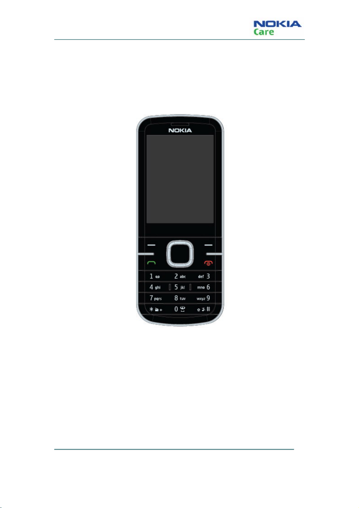
RM-583 (Nokia 3806) mobile terminal offers a CDMA single band engine and supports following
features:
Figure 1: View of RM-583
COMPANY CO NFIDENTIA L
Copyright © 2009 Nokia. All rights reserved.
Page 1-5 Issue 1
Page 18
RM-583 PCI overview
RM-583
General Information
COMPANY CO NFIDENTIA L
Issue 1 Page 1-6
Copyright © 2009 Nokia. All rights reserved.
Page 19

RM-583
General Information
Phone features and sales package
Hardware & Mechanics
z 800MHz, CDMA2000 1xRTT
z 2.2” 240*320 QVGA, 262K
z Camera 1.92MP
z 4-way Navigation Keys
z Internal antenna
z IHF speaker
z Battery (860mAh, BL-4C)
z FM radio
z RUIM
z 2.5mm stereo and mono headset jack
z Micro-USB 2.0
z White Backlighting
z Lanyard notch/ hole
z Bluetooth 2.1
z SDCC 2.0
SW
z Brew 3.1
z Voice mail
z Multimedia (music/video/media player)
z Download/DRM
z Keypad lock via software
z WAP browser
z Long SMS, MMS, Instant Messaging and vCard
z Alarm Clock; Calculator; Calendar; Timer; World Clock; Translator Application
z OTAPA/OTASP supported
COMPANY CO NFIDENTIA L
Copyright © 2009 Nokia. All rights reserved.
Page 1-7 Issue 1
Page 20
z Airplane Mode supported
z OMSI Interface supported
z Support GIF,JPG,PNG image formats and BMP image formats
z 72 polyphonic chords, MIDI, AAC, AAC+, EAAC+, MP3 supported
Sales package contents
z Transceiver: RM-583
z Standard Battery (860 mAh Li-on): BL-4C
z Charger: AC-6
z User Guide
RM-583
General Information
Accessories
Supported accessories
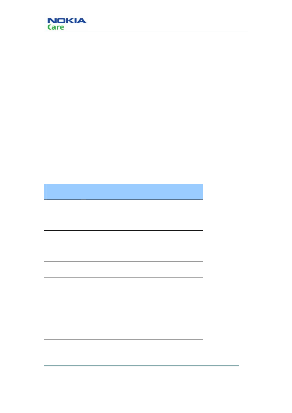
Type Name
DC-6 Car Charger
AC-6 Travel Charger
HF200 Car Kits
HS-47 Stereo Headset
WH-200 Mono Headset
BH214 Stereo Bluetooth
BH104 Mono Bluetooth
HF310 BT speakerphone
CA-101 Micro USB Cable
COMPANY CO NFIDENTIA L
Issue 1 Page 1-8
Copyright © 2009 Nokia. All rights reserved.
Page 21
RM-583
General Information
Technical Specifications
General specifications
Unit Dimension (mm) Weight(g) Volume(cc)
Transceiver with
110*45.4*12.5 83.5 54
BL-4C;860 mAh Li-Ion
battery pack
Battery endurance
Battery NMP Talk Time NMP standby Time
BL-4C 860 mAh Li-ion 5hours China 2 to 8.3 days
SEAP/MEA/LTA 4 to 8.3 days
COMPANY CO NFIDENTIA L
Copyright © 2009 Nokia. All rights reserved.
Page 1-9 Issue 1
Page 22

RM-583
General Information
(This page left intentionally blank.)
COMPANY CO NFIDENTIA L
Copyright © 2009 Nokia. All rights reserved.
Issue 1 Page 1-10
Page 23

Nokia Customer Care
2- Parts Lists and Exploded View
Issue 1
Copyright © 2009 Nokia. All rights reserved.
COMPANY CO NFIDENTIA L
Page 2-1
Page 24

RM-583
Parts lists and Exploded View
(This page left intentionally blank.)
COMPANY CO NFIDENTIA L
Copyright © 2009 Nokia. All rights reserved.
Issue 1 Page 2-2
Page 25

RM-583
Parts lists and Exploded View
Table of Contents
Phone exploded view........................................................................................................................page 2-5
Spare parts overview........................................................................................................................page 2-5
Issue 1
COMPANY CO NFIDENTIA L
Copyright © 2009 Nokia. All rights reserved.
Page 2-3
Page 26

RM-583
Parts lists and Exploded View
(This page left intentionally blank.)
COMPANY CO NFIDENTIA L
Copyright © 2009 Nokia. All rights reserved.
Issue 1 Page 2-4
Page 27
RM-583
Parts lists and Exploded View
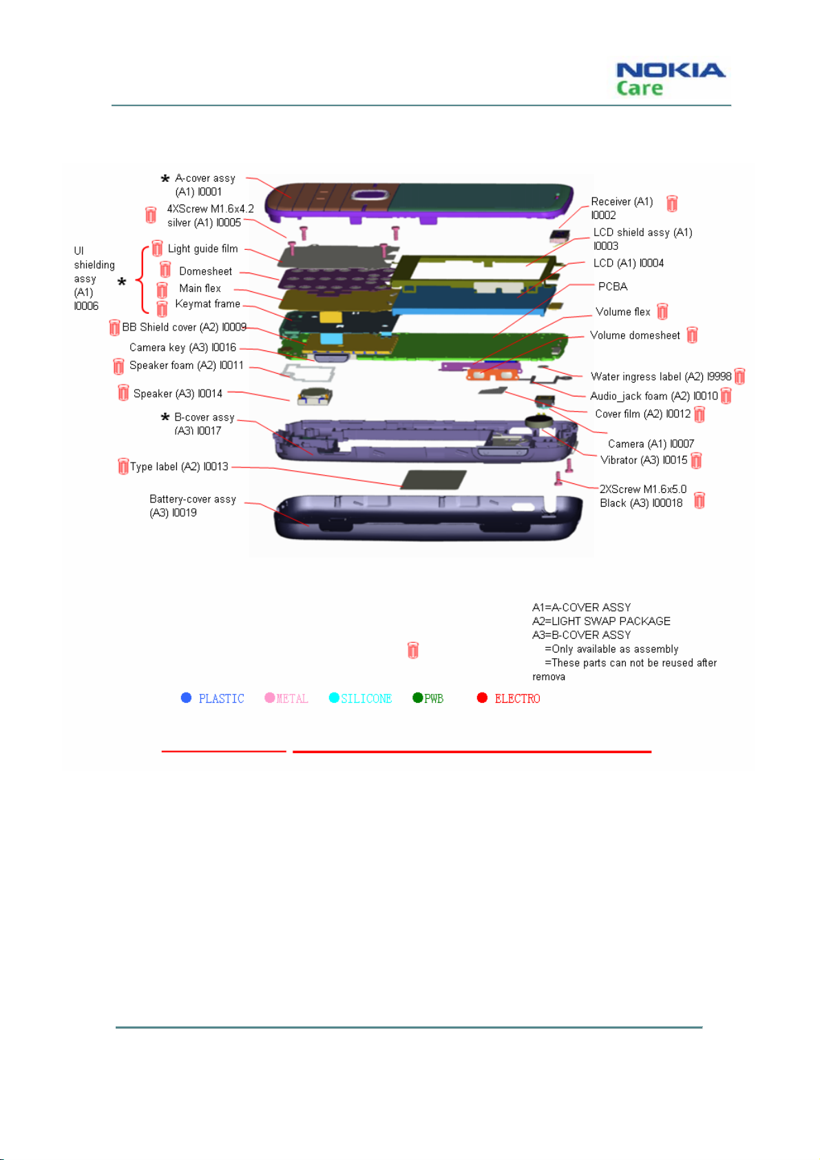
Phone exploded view
Spare parts overview
Spare parts list
Refer to the latest Service Bulletins (spare parts, SWAP units and service tools) on the Nokia Onl ine website for
RM-583 (Nokia 3806).
COMPANY CO NFIDENTIA L
Copyright © 2009 Nokia. All rights reserved.
Page 2-5Issue 1
Page 28

RM-583
Parts lists and Exploded View
(This page left intentionally blank.)
COMPANY CO NFIDENTIA L
Copyright © 2009 Nokia. All rights reserved.
Issue 1 Page 2-6
Page 29

Nokia Customer Care
3- Service Software Instructions
Issue 1
Copyright © 2009 Nokia. All rights reserved.
COMPANY CO NFIDENTIA L
Page 3-1
Page 30

RM-583
Service Software Instruction
(This page left intentionally blank.)
COMPANY CO NFIDENTIA L
Copyright © 2009 Nokia. All rights reserved.
Issue 1 Page 3-2
Page 31

RM-583
Service Software Instruction
Table of Contents
Software summary.............................................................................................................................page 3-5
Hardware, operating system and environment request................................................... page 3-5
Software utilization......................................................................................................... page 3-5
Installation..................................................................................................................... page 3-5
Use of AMS...........................................................................................................................page 3-18
Bload mode...................................................................................................................page 3-18
General mode.......................................................................................................................... page 3-25
Issue 1 Page 3-3
COMPANY CO NFIDENTIA L
Copyright © 2009 Nokia. All rights reserved.
Page 32

RM-583
Service Software Instruction
(This page left intentionally blank.)
COMPANY CO NFIDENTIA L
Copyright © 2009 Nokia. All rights reserved.
Issue 1 Page 3-4
Page 33

RM-583
Service Software Instruction
Software summary
In order to understand the requests of operating device and driver for the software, the user should read
this chapter carefully before using Nokia 3806 AMS tool.
Hardware, operating system and environment request
Operating system: Windows XP, Windows Vista
PC Minimum Requirement
Processor 1000MHz
RAM 256MB
Required Disk space 500MB
Interface ports USB
Table.1 Lowest request for Hardware configuration
Software utilization
Insert dongle
AMS has two function modes: Bload mo de and Gene ral mode. When in Bload mode, the handset must
be working in Bload mode. When in general m od e, the handset must be working in power up mode.
Bload mode only has one type: Download.
General mode includes seven types: Download, PRI Operation, Display Capture, Label Printing, RF
Backup, RF Calibration and Write NV.
Installation
Follow the steps below to install Nokia 3806 AMS tool successfully:
1. First, install Phone driver and Dongle driver separately.
Issue 1 Page 3-5
COMPANY CO NFIDENTIA L
Copyright © 2009 Nokia. All rights reserved.
Page 34

2. Second, install AMS software directly.
3. Third, install Calibration Tool Run Time, which supports RF calibration.
Steps for installing phone driver
1. Double click the NOKIA 3806 USB DRIVER Ver1.1.msi.
2. Click “Next” to continue with the following steps.
RM-583
Service Software Instruction
COMPANY CO NFIDENTIA L
Copyright © 2009 Nokia. All rights reserved.
Issue 1 Page 3-6
Page 35

RM-583
Service Software Instruction
3. Click “Install” to continue with the following steps.
Issue 1 Page 3-7
COMPANY CO NFIDENTIA L
Copyright © 2009 Nokia. All rights reserved.
Page 36

4. Click “Finish” button to complete the installation.
RM-583
Service Software Instruction
Steps for installing dongle driver
Note: If you don’t have dongle, you must have User ID and password, otherwise you can’t use AMS
tool.
1. Double click Sentinel System Driver Installer 7.5.0.exe.
2. Click “Next” to continue with the following steps.
COMPANY CO NFIDENTIA L
Copyright © 2009 Nokia. All rights reserved.
Issue 1 Page 3-8
Page 37

RM-583
Service Software Instruction
3. Select “I accept the license ag reeme nt ”, then click “Next” but ton.
Issue 1 Page 3-9
COMPANY CO NFIDENTIA L
Copyright © 2009 Nokia. All rights reserved.
Page 38

4. Select “Complete” setup type then click “Next” button.
RM-583
Service Software Instruction
COMPANY CO NFIDENTIA L
Copyright © 2009 Nokia. All rights reserved.
Issue 1 Page 3-10
Page 39

RM-583
Service Software Instruction
5. Click “Install” to continue with the following steps.
Issue 1 Page 3-11
COMPANY CO NFIDENTIA L
Copyright © 2009 Nokia. All rights reserved.
Page 40

6. Click “Finish” button to complete the installation.
RM-583
Service Software Instruction
Steps for installing calibration tool run time
1. Double click setup.exe.
2. Click “Next” to continue with the following steps.
COMPANY CO NFIDENTIA L
Copyright © 2009 Nokia. All rights reserved.
Issue 1 Page 3-12
Page 41

RM-583
Service Software Instruction
Issue 1 Page 3-13
COMPANY CO NFIDENTIA L
Copyright © 2009 Nokia. All rights reserved.
Page 42

3. Select “I accept the License Agreement(s)” and “Next ”.
RM-583
Service Software Instruction
COMPANY CO NFIDENTIA L
Copyright © 2009 Nokia. All rights reserved.
Issue 1 Page 3-14
Page 43

RM-583
Service Software Instruction
Issue 1 Page 3-15
COMPANY CO NFIDENTIA L
Copyright © 2009 Nokia. All rights reserved.
Page 44

4. Click “Next ”.
RM-583
Service Software Instruction
COMPANY CO NFIDENTIA L
Copyright © 2009 Nokia. All rights reserved.
Issue 1 Page 3-16
Page 45

RM-583
Service Software Instruction
5. Waiting for installati on.
Issue 1 Page 3-17
COMPANY CO NFIDENTIA L
Copyright © 2009 Nokia. All rights reserved.
Page 46

6. Click “Finish” button to complete the installation.
RM-583
Service Software Instruction
Use of AMS
Bload mode
Download
First install the SW package in the local PC to support the download. This package contains all the BIN
files requested by the phone, which are also supported on the general mode.
Follow the steps below to enter the download mod e:
1. Resume power supply after the mobile phone is powered off.
2. Press “Down key” for about 5 seconds till USB cable is connected between the PC and the phone.
Steps for installing package
1. Double-click the package you want to install. It disp lays as below.
COMPANY CO NFIDENTIA L
Copyright © 2009 Nokia. All rights reserved.
Issue 1 Page 3-18
Page 47

RM-583
Service Software Instruction
2. Click “Next >”.
3. Click “Install” to start the installation.
Issue 1 Page 3-19
COMPANY CO NFIDENTIA L
Copyright © 2009 Nokia. All rights reserved.
Page 48

RM-583
Service Software Instruction
4. Installing.
COMPANY CO NFIDENTIA L
Copyright © 2009 Nokia. All rights reserved.
Issue 1 Page 3-20
Page 49

RM-583
Service Software Instruction
5. Wait until the installation is finished.
The “Download” tab will show all available software versions for update according to the CPC code
input by you or by the combo box.
1. Click the “Download” tab.
Issue 1 Page 3-21
COMPANY CO NFIDENTIA L
Copyright © 2009 Nokia. All rights reserved.
Page 50

RM-583
Service Software Instruction
COMPANY CO NFIDENTIA L
Copyright © 2009 Nokia. All rights reserved.
Issue 1 Page 3-22
Page 51

RM-583
Service Software Instruction
2. Input CPC cod e or select CPC code from combo box, click “Search SW Version” button.
Note: If the warning dialog pops up, refer to below instructions:
1. You have input an incorrect CPC code.
2. Yo u have not installed the appropriate package.
3. Select the exa ct SW Version you need.
Issue 1 Page 3-23
COMPANY CO NFIDENTIA L
Copyright © 2009 Nokia. All rights reserved.
Page 52

RM-583
Service Software Instruction
COMPANY CO NFIDENTIA L
Copyright © 2009 Nokia. All rights reserved.
Issue 1 Page 3-24
Page 53

RM-583
Service Software Instruction
4. Click “Start” to start download.
5. Wait till the downl oad is 100% completed.
General mode
General Mode provides seven functions, they are “Download”, “Display Capture”, “Label Printing”,
“Write NV “, “RF Backup”, “PRI Operation” and “RF Calibration”.
Note: The handset must be in Power Up status.
Download
“Download” function in General mode is same as that in Bload mode. Details please refer to Page 3-23.
Issue 1 Page 3-25
COMPANY CO NFIDENTIA L
Copyright © 2009 Nokia. All rights reserved.
Page 54

Service Software Instruction
PRI operation
PRI settings editor
PRI Settings Editor supports loading the file on PC to P hone, reading and writing PRI NV value.
1. Click “PRI Operation” on the left panel to enter PRI operation interface:
RM-583
COMPANY CO NFIDENTIA L
Copyright © 2009 Nokia. All rights reserved.
Issue 1 Page 3-26
Page 55

RM-583
Service Software Instruction
2. Click “Read” button to read the PRI NV value from the Phone.
Issue 1 Page 3-27
COMPANY CO NFIDENTIA L
Copyright © 2009 Nokia. All rights reserved.
Page 56

RM-583
Service Software Instruction
COMPANY CO NFIDENTIA L
Copyright © 2009 Nokia. All rights reserved.
Issue 1 Page 3-28
Page 57

RM-583
Service Software Instruction
3. Click “NAM” and choose the N V you need.
Issue 1 Page 3-29
COMPANY CO NFIDENTIA L
Copyright © 2009 Nokia. All rights reserved.
Page 58

4. Click “Search” to find the NV item by NV ID o r NV name and then “Find”.
RM-583
Service Software Instruction
COMPANY CO NFIDENTIA L
Issue 1 Page 3-30
Copyright © 2009 Nokia. All rights reserved.
Page 59

RM-583
Service Software Instruction
5. Double click PRI NV item to change PRI NV value.
Double click them to
change the value
6. Click “Write” and “Save to file” to write PRI NV value to phone.
7. Click “Open” to open a PRI file on PC to write to the phone.
Issue 1 Page 3-31
COMPANY CO NFIDENTIA L
Copyright © 2009 Nokia. All rights reserved.
Page 60

RM-583
Service Software Instruction
8. Repeat steps 4 to 7.
PRI compare
PRI Compare compares two PRI files and indicates the difference between them.
Note: Before the compare operation, you must read the PRI from the phone o nce.
1. Click “PRI Compare” to enter PRI compare interface.
COMPANY CO NFIDENTIA L
Copyright © 2009 Nokia. All rights reserved.
Issue 1 Page 3-32
Page 61

RM-583
Service Software Instruction
2. Select two PRI files on PC by “Browse…” button.
3. Click “Start”, the comparison will be shown on the list left.
Issue 1 Page 3-33
COMPANY CO NFIDENTIA L
Copyright © 2009 Nokia. All rights reserved.
Page 62

RM-583
Service Software Instruction
COMPANY CO NFIDENTIA L
Copyright © 2009 Nokia. All rights reserved.
Issue 1 Page 3-34
Page 63

RM-583
Service Software Instruction
4. Click “+” to see the detailed difference of each NV it em.
5. Save the difference by “Save as” button.
Label printing
Label Printing is used to print out the product label. Read out th e data from the handset first, transfer
into file and print it out.
Set up the printer
Select Start->Control panel->Printer and fax on your PC.
Issue 1 Page 3-35
COMPANY CO NFIDENTIA L
Copyright © 2009 Nokia. All rights reserved.
Page 64

Service Software Instruction
1. Click right button to set Zebra 110XiIII Plus (600dpi) printer as the default printer.
Right click the icon, select Properties, choose Port sheet, select Lpt1 port
RM-583
Click “OK” button, finish the configuration.
COMPANY CO NFIDENTIA L
Copyright © 2009 Nokia. All rights reserved.
Issue 1 Page 3-36
Page 65

RM-583
Service Software Instruction
2. Click “Label Printing” button to enter label printing interface:
3. Click “Refresh”.
4. Read out data and transfer into printing file.
Issue 1 Page 3-37
COMPANY CO NFIDENTIA L
Copyright © 2009 Nokia. All rights reserved.
Page 66

RM-583
Service Software Instruction
Note: Before printing, y ou can adjust X, Y offset for proper label printing configuration if needed, the
default coordinate of the label’s top-left corner is set as (0, 0). Only the lat est X, Y offset adjusted by you
will be reserved when you open the tool next time.
5. Click “print” to start printing.
RF backup
Critical Data Backup is used to backup the data, N V, RF parameters.
1. Switch to “RF Backup”:
COMPANY CO NFIDENTIA L
Copyright © 2009 Nokia. All rights reserved.
Issue 1 Page 3-38
Page 67

RM-583
Service Software Instruction
Issue 1 Page 3-39
COMPANY CO NFIDENTIA L
Copyright © 2009 Nokia. All rights reserved.
Page 68

2. Click “Backup”.
RM-583
Service Software Instruction
COMPANY CO NFIDENTIA L
Copyright © 2009 Nokia. All rights reserved.
Issue 1 Page 3-40
Page 69

RM-583
Service Software Instruction
3. Backup succ essfully.
RF calibration
RF calibration is a tool for automatic tuning of RF values. Check the hardware setup before the
calibration.
Issue 1 Page 3-41
COMPANY CO NFIDENTIA L
Copyright © 2009 Nokia. All rights reserved.
Page 70

RM-583
Service Software Instruction
1. Click “RF Calibration”.
COMPANY CO NFIDENTIA L
Copyright © 2009 Nokia. All rights reserved.
Issue 1 Page 3-42
Page 71

RM-583
Service Software Instruction
2.1 Log Display
Log Display: Show calibration information.
2.2 Control Setting and information
Text information: Show test information.
Start button: Start tuning.
3. Program Setting
There are two files which need to be configured before using the tool:
3.1 Sysconfig.ini
3.1.1 [COM]
9 The section is to set com port number and its baud rate. If using RS232 Cable between PC and
DUT’s UART1, see “Hardware Connection”, then:
ComPort = 1 or 2;
9 Note: It is recommended to use UART1 to communicate wi th PC; if using USB cable between PC
Issue 1 Page 3-43
COMPANY CO NFIDENTIA L
Copyright © 2009 Nokia. All rights reserved.
Page 72

RM-583
Service Software Instruction
and DUTUSB port, see “Hardware Connection”.
ComPort = above 2
9 depend on the port number in “Device manager” of PC);
Baudrate=115200
9 default setting,
3.1.2 [Call Box]
9 the section is to select the radio communication test set and set its primary address, see below:
Type=2 (1:cmu200,2:hp8960)
9 Address=14
3.1.3 [PS]
9 the section is to select the power supply type and set its address and voltage if control by remote;
Type=0;
9 0:no, 0: indicates the power supply is used without GPIB remote, PS, 1:E3631A, 2:HP66309,
3:HP66311, 4:Keithley2306, 5:Keithley2304
Address=5
NormalVoltage=3.7
LowVoltage=3.2
9 For Low Battery Calibraton
HighVoltage=4.2
9 For High Battery Calibration
3.1.4 [cable loss]
9 The section is to set the using RF cable’s loss;
3.1.5 [T est item]
Item = 1
9 The Item is always set to 1;
3.2 Sysconfig.ini
9 In the file, only “[CaliItem]” section is required to select item to calibrate; other Sections include test
parameters and test specification, which can not be changed.
3.2.1 [CaliItem]
COMPANY CO NFIDENTIA L
Copyright © 2009 Nokia. All rights reserved.
Issue 1 Page 3-44
Page 73

RM-583
Service Software Instruction
VBat=0
CalCell=1
CalPCS=0
GPSTest=0
9 Note: 0: indicates “Not Select”; 1: indicates “Select”.
4. Turn on device
Make sure that which com port is used, and connect all ki nds of cable sh own as “H ardwa re Conn ection ”,
configure sysconfig.ini and calibrationconfig.ini according to the introduction above;
5. Start Test
Click “Start” Button, pop up input dialog and i np ut d evice serial number, shown as below
After input serial number, Press “Enter” key to begin to calibrate, shown as below:
Issue 1 Page 3-45
COMPANY CO NFIDENTIA L
Copyright © 2009 Nokia. All rights reserved.
Page 74

RM-583
Service Software Instruction
Waiting for about 80s, till calibration pass, shown as below:
COMPANY CO NFIDENTIA L
Copyright © 2009 Nokia. All rights reserved.
Issue 1 Page 3-46
Page 75

RM-583
Service Software Instruction
Display capture
Display Capture supports screen capture.
1. Click “Disp lay Capture”.
Issue 1 Page 3-47
COMPANY CO NFIDENTIA L
Copyright © 2009 Nokia. All rights reserved.
Page 76

2. Click “Capture”:
RM-583
Service Software Instruction
3. Save the picture to PC by “Save as” or clear the picture by “Clear”.
Write NV
“Write NV” function supports Phone NV value set.
1. Click “Write NV”:
COMPANY CO NFIDENTIA L
Copyright © 2009 Nokia. All rights reserved.
Issue 1 Page 3-48
Page 77

RM-583
Service Software Instruction
2. Click “Write” to write the N V value.
Issue 1 Page 3-49
COMPANY CO NFIDENTIA L
Copyright © 2009 Nokia. All rights reserved.
Page 78

RM-583
Service Software Instruction
3. When all NV are written, a pop-up is displayed.
4. Click “Refres h” to see the updated Phone information.
COMPANY CO NFIDENTIA L
Copyright © 2009 Nokia. All rights reserved.
Issue 1 Page 3-50
Page 79

Nokia Customer Care
4- Service Tools
Issue 1
Copyright © 2009 Nokia. All rights reserved.
COMPANY CO NFIDENTIA L
Page 4-1
Page 80

RM-583
Service Tools
(This page left intentionally blank.)
COMPANY CO NFIDENTIA L
Copyright © 2009 Nokia. All rights reserved.
Issue 1 Page 4-2
Page 81

RM-583
Service Tools
Table of Contents
Introduction ........................................................................................................................... page 4-5
L3 service configuration......................................................................................................... page 4-5
Service tools.................................................................................................................. page 4-5
L3 service configuration................................................................................................. page 4-6
MJ-272 handling instructions................................................................................................. page 4-6
External connections & switch instructions.................................................................... page 4-6
MJ-272 PWB pin definition.............................................................................................. page 4-8
Handling instruction....................................................................................................... page 4-8
Power on sequence...............................................................................................................page 4-11
AC power supply...........................................................................................................page 4-11
DC power supply...........................................................................................................page 4-12
Issue 1
COMPANY CO NFIDENTIA L
Copyright © 2009 Nokia. All rights reserved.
Page 4-3
Page 82

RM-583
Service Tools
(This page left intentionally blank.)
COMPANY CO NFIDENTIA L
Copyright © 2009 Nokia. All rights reserved.
Issue 1 Page 4-4
Page 83

RM-583
Service Tools
Introduction
This document explains relevant service softwar e, service tools and handling instructions for RM-583.
Service configuration
Service tools
The table below gives an overview of servic e tools with M odu le jig t hat woul d be us ed in servi ce testing,
tuning and error analysis.
CA-101 Data Service Cable
This cable provides a connection from the USB port of the personal
computer or notebook to the micro USB connector of the phone and
allows Point of Sale (POS) locations to flash the mobile terminal.
MJ-272 Module Jig
This jig allows PWB-level service and troubleshooting. It supports
regulated and unregulated DC input voltag es, a headset jack for audio
tests and a RUIM card reader. It also supports simultaneous RF
connections to the CDMA engine.
AK05G-0650400W2 AC power adapter
This AC power adapter (with 5.50mm power cord connector) is used to
provide DC power to the mobile ph one and service tools (e.g. Module
Jig) from power supply for CDMA tuning (packaged with the module jig).
CA-128RS RF Service Cable
This test cable is used for RF engine testing and tuning. It snaps directly
on the mobile terminal’s RF connector and converts the output to a
Issue 1
surface mounting assembly connector.
COMPANY CO NFIDENTIA L
Copyright © 2009 Nokia. All rights reserved.
Page 4-5
Page 84

PK-86 AMS SW Protection Key
This hardware dongle connected to the USB port of the service
computer, enables the use of the service software. It is not possible to
use the service software without the dongle.
Service configuration
The following diagram illustrates service setup with Module Jig.
RM-583
Service Tools
MJ-272 handling instructions
External connections & switch instructions
COMPANY CO NFIDENTIA L
Copyright © 2009 Nokia. All rights reserved.
Issue 1 Page 4-6
Page 85

RM-583
Service Tools
1- Micro USB c onnect or
2- CN5 & CN7 for current meter (0~1A)
3- CN4 & CN6 for backup power supply
4- CN3 Main power supply (Vcc: 6.5V~7.5V)
5- RF connector
6- UIM slot
7- S2 switch for download and test mode (will be removed in MP stage)
8- S3 switch for power on and off
9- S1 switch for current measurement
10- S4 switch for main power and backup power supply
Issue 1
COMPANY CO NFIDENTIA L
Copyright © 2009 Nokia. All rights reserved.
Page 4-7
Page 86

MJ-272 PWB pin definition
RM-583
Service Tools
Handling instruction
1. Put PWB onto the module jig.
COMPANY CO NFIDENTIA L
Copyright © 2009 Nokia. All rights reserved.
Issue 1 Page 4-8
Page 87

RM-583
Service Tools
2. Close the module jig up.
Issue 1
COMPANY CO NFIDENTIA L
Copyright © 2009 Nokia. All rights reserved.
Page 4-9
Page 88

RM-583
Service Tools
3. Connectio n with PC
COMPANY CO NFIDENTIA L
Copyright © 2009 Nokia. All rights reserved.
Issue 1 Page 4-10
Page 89

RM-583
Service Tools
1) RF calibration
RF Cable provides a connection from RF connector on the jig to RF connector on CMU200 or
Agilent8960 and executes RF calibration function in AMS.
2) SW update / flashing
USB Cable CA-101 provides a connection from the USB p ort of the personal computer or notebook to
the micro USB connector on Module jig for SW update/flashing.
3) Full Phone functionality
Press *0521# in idle mode to enter test mode > manual test to perform full phone functionality check.
Power on sequence
AC power supply
1. S4 @right Vcc1:6.5V-7.5V,Imax=1A;
2. S1@right measure main current with current meter;
Issue 1
COMPANY CO NFIDENTIA L
Copyright © 2009 Nokia. All rights reserved.
Page 4-11
Page 90

3. S3@right power on.
DC power supply
RM-583
Service Tools
1. S4 @left V
2. S
@right power on.
3
: 3.7V~4.2V;
cc2
COMPANY CO NFIDENTIA L
Copyright © 2009 Nokia. All rights reserved.
Issue 1 Page 4-12
Page 91

Nokia Customer Care
5- Antenna Description
Issue 1
Copyright © 2009 Nokia. All rights reserved.
COMPANY CO NFIDENTIA L
Page 5-1
Page 92

Antenna Description and Troubleshooting
(This page left intentionally blank.)
Page 5-2 Issue 1
COMPANY CO NFIDENTIA L
RM-583
Copyright © 2009 Nokia. All rights reserved.
Page 93

RM-583
Antenna Description and Troubleshooting
Table of Contents
Introduction ...................................................................................................................................................... page 5-5
Visual quality requirements................................................................................................................... page 5-5
Failures and corrective measures.................................................................................................................. page 5-5
Damaged RF feed point pin.................................................................................................................... page 5-6
Obstructed RF feed point pad........................................................................................................................ page 5-7
RF connector failure........................................................................................................................................ page 5-8
Issue 1
COMPANY CO NFIDENTIA L
Page 5-3
Copyright © 2009 Nokia. All rights reserved.
Page 94

RM-583
Antenna Description and Troubleshooting
(This page left intentionally blank.)
Page 5-4 Issue 1
COMPANY CO NFIDENTIA L
Copyright © 2009 Nokia. All rights reserved.
Page 95

RM-583
Antenna Description and Troubleshooting
Introduction
RM-583 includes two internal antennas. On e is for cellular frequency bands and this internal ant enna assembly
adopts PIFA Antenna structure for the cellular engine, the other is for Bluetooth module, a PIFA antenna too,
Visual quality requirements
Below are the minimum acceptable visual quality req uirements of the internal antenna assembly:
z Wear gloves to assemble the antenna. Don’t touch the antenna radiator with bare hands.
z No visual cracks or mechanical defects.
z No oil, dirt or particles attached on the parts.
z Radiator must be flat without warping and aligned with the plastic housing.
z The length of all pins must be identical and the pins align.
Failures and corrective measures
The two antennas are assembled i nto B Cover as shown in Figure 1. If no internal antenna is installed, the
antenna gain is degraded by more than 2 0 dB.
z If the internal antenna is missing, install antenna-a sm Module.
z If the radiator is damaged, replace it with a new ante nna-asm Module.
Figure 1: B Cover Assembly
Issue 1
COMPANY CO NFIDENTIA L
Copyright © 2009 Nokia. All rights reserved.
Page 5-5
Page 96

RM-583
Antenna Description and Troubleshooting
Damaged RF feed point pin
The pin (spring clip) of the antenna must be properly connected to the PWB.
z If the main antenna’s RF feed point pin does not touch the PWB, the antenna gain degrades by more than
17 dB.
z If the RF feed pin is broken or bent, replace the anten na-asm Module.
z If the RF feed pin spring turns out damaged, replace the antenna-asm Module.
Figure 2: Back view of internal antennas
Page 5-6 Issue 1
COMPANY CO NFIDENTIA L
Copyright © 2009 Nokia. All rights reserved.
Page 97

RM-583
Antenna Description and Troubleshooting
Obstructed RF feed point pad
If the RF feed point pad is obstructed, removed or covered , the antenna pin does not touch the PWB and the
antenna performance degrades.
z If there is any corrosion or the pad is missing, replace th e PWB.
z If a pad is obstructed or covered by something, clea n the pad.
z If any component of antenna match circuit is missing, r ep lace the related component.
Figure 3: PWB layout of RF feed point and antenna match circuit for main antenna
Figure 4: PWB layout of RF feed point and antenna match circuit for Bluetooth antenna
Issue 1
COMPANY CO NFIDENTIA L
Copyright © 2009 Nokia. All rights reserved.
Page 5-7
Page 98

RM-583
Antenna Description and Troubleshooting
RF connector failure
The RF connector fails when it does not properly connect RF input terminal to RF output terminal during
SMT. If this happens the antenna gain degrades by 25 dB. Check this failure by measuring the
resistance value between the input and out put of RF connector, if the value is close to zero, replace the
RF connector.
Note: Do not insert RF cable to RF connector when testing the resistance value. Because the RF
connector is also a switch, when RF cable is inserted, RF output is d isconnected from RF input.
z RF input terminal – connect to duplexer.
z RF output terminal – connect to the antenn a pad through antenna match circuit.
z RF connector terminal – connect to RF coaxial cable.
Figure 5: RF input / output terminal for main antenna
Page 5-8 Issue 1
COMPANY CO NFIDENTIA L
Copyright © 2009 Nokia. All rights reserved.
Page 99

Nokia Customer Care
6- Baseband Description and
Troubleshooting
Issue 1
Copyright © 2009 Nokia. All rights reserved.
COMPANY CO NFIDENTIA L
Page 6-1
Page 100

RM-583
Baseband Description and Troubleshooting
(This page left intentionally blank.)
COMPANY CO NFIDENTIA L
Copyright © 2009 Nokia. All rights reserved.
Issue 1 Page 6-2
 Loading...