

Page 1

Nokia Customer Care
2505 (RM-307)
Mobile Terminal
Technical Summary
Issue 1 04/2007 Company Confidential © 2007 Nokia Corporation
Page 2

2505 (RM-307)
Technical Summary
Contents Page
Introduction............................................................................................................... 3
Sales Package ..................................................................................................4
Supported Accessories......................................................................................4
Exploded View.......................................................................................................... 5
Assembly Parts List...........................................................................................6
Baseband Module Overview.................................................................................... 7
QSC6010TM.......................................................................................................7
Flash Memory....................................................................................................8
RF Module Overview................................................................................................ 9
Transmitter........................................................................................................9
Receiver............................................................................................................9
Page 2 © 2007 Nokia Corporation Company Confidential Issue 1 04/2007
Page 3
2505 (RM-307)
Nokia Customer Care Technical Summary
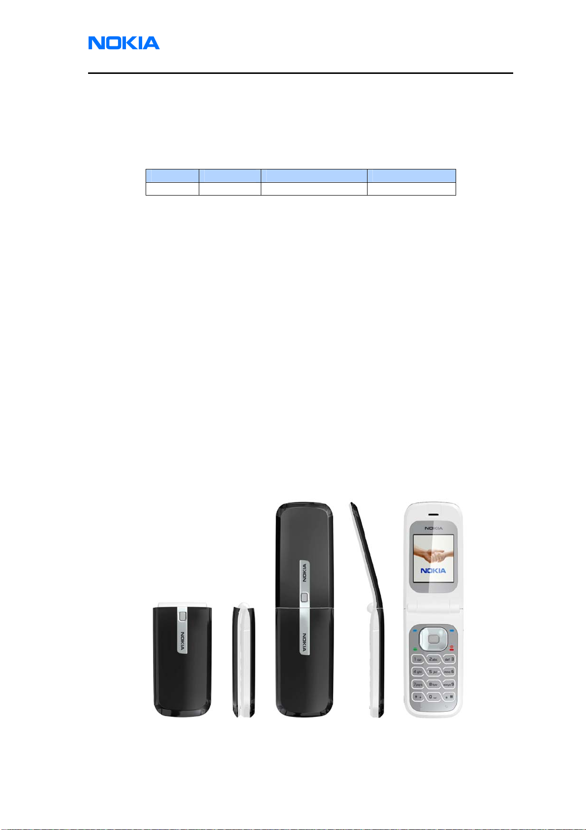
Introduction
The Nokia 2505 mobile terminal offers a CDMA single band engine and includes
the following features:
Model Type Frequency(MHz) GPS Module
2505 RM-307 800 No
z 800MHz, IS95, CDMA2000 1xRTT
z 128 x 160 pixel color display with 65K colors
z Removable User Information Module (RUIM), disabled in non-RUIM markets
z Internal antenna
z Internal vibra
z EVRC Vocoder
z 32 polyphonic MIDI ringtone and 30 pre-loaded ringtones
z Predictive text
z Speakerphone
z FM Radio
z Flashlight
z 4-way navigation key for easy navigation
z Calendar, alarm clock, calculator, stopwatch, countdown timer and voice memo
z 3 pre-loaded games and 10 pre-loaded wallpapers
z Downloadable ringtones and wallpapers via BREW
Issue 1 04/2007 © 2007 Nokia Corporation Company Confidential Page 3
Page 4

2505 (RM-307)
Technical Summary
Parameter Value and Unit
BL-4B
Talk time
Standby time
Dimensions:
Volume
Length
Width
Thickness
Weight
Up to 180 minutes
Up to 168 hours
50.7 cc
82 mm
42 mm
16.65 mm
63 grams (w/ battery)
Sales Package
Name Type
Transceiver RM-307
Standard Battery
(700 mAh Li-Ion)
Charger AC-3
Headset HS-9 (Optional)
Product literature,
user guide and
quick start guide
Carrier specific
literature
BL-4B
Supported Accessories
Type Name
AC-3 Compact Charger
AC-4 Travel Charger
DC-4 Car Power Adapter
ACP-12 Travel Charger
AC-5 Charger
CA-44 Charger Adapter
HS-9 CDMA 2.5mm headset
BL-4B (700mAh) Battery
Page 4 © 2007 Nokia Corporation Company Confidential Issue 1 04/2007
Page 5

Nokia Customer Care Technical Summary
Exploded View
Keymat
Keymat
I0009
I0009
Shaft Alloy (A2)
Shaft Alloy (A2)
I0010
I0010
C Cover Sub-Assy(A2)
C Cover Sub-Assy(A2)
I0011
*
I0011
*
Earphone Jack Cover
Earphone Jack Cover
I0012
I0012
Domesheet Assy (A5)
Domesheet Assy (A5)
I0016
I0016
Microphone (A5)
Microphone (A5)
I0017
I0017
Engine Module (A5)
Engine Module (A5)
I0018
I0018
2505 (RM-307)
Left Screw Cover
Left Screw Cover
I0001
I0001
Screw M1.4X2.8
Screw M1.4X2.8
I0003
I0003
Right Screw Cover
Right Screw Cover
I0002
I0002
Lens Protect Film (A1)
Lens Protect Film (A1)
I0004
I0004
B Cover Sub-Assy (A1)
B Cover Sub-Assy (A1)
I0005 *
I0005 *
Hinge (A1)
Hinge (A1)
I0006
I0006
Speaker (A1)
Speaker (A1)
I0008
I0008
Magnet (A1)
Magnet (A1)
I0007
I0007
LCD Module Assy (A3)
LCD Module Assy (A3)
I0013
I0013
Main Shielding Cover (A5)
Main Shielding Cover (A5)
I0019
I0019
Type Label
Type Label
I0021
I0021
DC Jack (A6)
DC Jack (A6)
I0022
I0022
Microphone Guider (A6)
Microphone Guider (A6)
I0023
I0023
D Cover Sub-Assy(A6)
D Cover Sub-Assy(A6)
I0027 *
I0027 *
Earphone Jack (A6)
Earphone Jack (A6)
I0028
I0028
Screw D14X0.57X4mm
Screw D14X0.57X4mm
I0030
I0030
Batter y Cover Assy
Batter y Cover Assy
I0031
I0031
Disposal Legend:
Disposal Legend:
Disposal Legend:
Silicon Metal Plastic PWB Cover
Silicon Metal Plastic PWB Cover
Electro
Electro
Electro
SiliconSilicon Metal PlasticPlastic PWBPWB CoverCover
Button Stopper
Button Stopper
I0014
I0014
A Cover Assy (A4)
A Cover Assy (A4)
I0015
I0015
FM Shieldin g Co v er (A5)
FM Shieldin g Co v er (A5)
I0020
I0020
Vibrator Clip (A6)
Vibrator Clip (A6)
I0024
I0024
Vibrator (A6)
Vibrator (A6)
I0025
I0025
Vibrator Rubber (A6)
Vibrator Rubber (A6)
I0026
I0026
Earphone Jack Rubber (A6)
Earphone Jack Rubber (A6)
I0029
I0029
A1 = B Cover Assy
A1 = B Cover Assy
A2 = C Cover Assy
A2 = C Cover Assy
A3 = LCD Module Assy
A3 = LCD Module Assy
A4 = A Cover Assy
A4 = A Cover Assy
A5 = Engine Module Assy
A5 = Engine Module Assy
A6 = D Cover Assy
A6 = D Cover Assy
Only Available as Assembly
*
Only Available as Assembly
*
Issue 1 04/2007 © 2007 Nokia Corporation Company Confidential Page 5
Page 6

2505 (RM-307)
Technical Summary
Assembly Parts List
Qty Description CCT Code
1 Left Screw Cover I0001
1 Right Screw Cover I0002
2 Screw M1.4x2.8 I0003
1 Lens Protect Film I0004
1 B Cover Sub-Assy I0005
1 Hinge I0006
1 Magnet I0007
1 Speaker I0008
1 Keymat I0009
1 Shaft Alloy I0010
1 C Cover Sub-Assy I0011
1 Earphone Jack Cover I0012
1 LCD Module Assy I0013
1 Button Stopper I0014
1 A Cover Assy I0015
1 Domesheet Assy I0016
1 Microphone I0017
1 Engine Module I0018
1 Main Shielding Cover I0019
1 FM Shielding Cover I0020
1 Type Label I0021
1 DC Jack I0022
1 Microphone Guider I0023
1 Vibrator Clip I0024
1 Vibrator I0025
1 Vibrator Rubber I0026
1 D Cover Sub-Assy I0027
1 Earphone Jack I0028
1 Earphone Jack Rubber I0029
4 Screw D14X0.57X4mm I0030
1 Battery Cover Assy I0031
Page 6 © 2007 Nokia Corporation Company Confidential Issue 1 04/2007
Page 7

2505 (RM-307)
Nokia Customer Care Technical Summary
Baseband Module Overview
The mobile terminal uses a CDMA single mode engine (Cellular/ 800) with
Qualcomm baseband consisting of two ASICs:
z Qualcomm Single Chip 6010
z 64Mb Flash memory with 16Mb of Psram memory
QSC6010
TM
The QSC6010 device represents QCT’s next generation of chipset architecture
and enhancements for voice and entry-level multimedia handsets by integrating
Mobile Station Modem™ (MSM™) baseband, radioOne RF, and power
management functionality into a single 15 mm x 15 mm mini scale package (MSP).
Together these functions perform all of the signal processing and power
management tasks within a subscriber unit. This enables reduced handset
TM
complexity, cost, time to market, and board-space requirements while providing
many features and functionalities.
The QSC6010
TM
device integrates a mixed-signal baseband chip that enables
manufacturers to meet or exceed the specifications of mobile stations for
worldwide cdmaOne and 3G CDMA systems, including IS-95-A, IS-95-B, IS-2000
1x Release 0.
Subsystems within the QSC6010
TM
device include a CDMA processor, a DFM
processor, QCT’s QDSP4000™ DSP for voice compression, PLL and an ARM®
ARM926EJ-S™ microprocessor. Also integrated in the QSC6010
TM
device are an
audio voice codec and analog interfaces for the radioOne RF ASICs. Controllers
for an R-UIM, GPIOs, and peripheral interfaces complete the system integration.
The QSC6010
TM
device integrates all low-cost wireless handset power
management, general housekeeping, and user interface support functions into a
single mixed signal IC. Its versatile design is suitable for low-cost CDMA handsets.
The power management portion accepts power from common sources – battery,
external charger or adapter – and generates all the regulated voltages needed to
power the appropriate handset electronics. It monitors and controls the power
sources, detecting which sources are applied, verifying that they are within
acceptable operational limits, and coordinates battery recharging while maintaining
the handset electronics supply voltages. On-chip voltage regulators generate nine
Issue 1 04/2007 © 2007 Nokia Corporation Company Confidential Page 7
Page 8

2505 (RM-307)
Technical Summary
programmable output voltages using low dropout voltage regulators, all derived
from a common trimmed voltage reference.
Flash Memory
The Simultaneous Read/Write architecture provides simultaneous operation by
dividing the memory space into 4 banks, which can be considered to be four
separate memory arrays. The device can improve overall system performance by
allowing a host system to program or erase in one bank, then immediately and
simultaneously read from another bank with zero latency.
This device requires a single 3.0 volt power supply for both read and write functions.
Its command set is entirely compatible with the JEDEC single-power-supply Flash
standard.
Page 8 © 2007 Nokia Corporation Company Confidential Issue 1 04/2007
Page 9

2505 (RM-307)
Nokia Customer Care Technical Summary
RF Module Overview
The RF module receives and demodulates the radio frequency signals from the
base station and transmits the modulated RF signals to the base station. It
communicates between QSC6010 , PA and Antenna.
Transmitter
The transmitter module is a baseband -to- RF module, an integral component of
QUALCOMM’s QSC6010 chipset. All radioOne ICs are highly integrated and fulfill
CDMA2000 standard. Overall radioOne performance depends on the combined,
complementary performance of all the ICs in the chipset.
The transmitter module in the QSC6010 provides the Zero-IF transmit signal path
for Cellular-CDMA transmission. For this module, Cellular-CDMA refers to band
classes 0 as defined by the cdma2000 standard, with mobile station transmitters
operating between 824 and 849 MHz. The transmit signal path includes baseband
amplifiers, quadrature upconversion, gain control RF amplification, and an output
driver amplifier.
Receiver
The receiver module is an RF-to-baseband module, an integral component of
QUALCOMM’s QSC6010 chipset. All radioOne ICs are highly integrated and fulfill
CDMA2000 standard. Overall radioOne performance depends on the combined,
complementary performance of all the ICs in the chipset.
The receiver module in the QSC6010 provides the Zero-IF receiver signal path for
Cellular-CDMA reception. For this module, Cellular-CDMA refers to band classes 0
as defined by the cdma2000 standard, with mobile station receivers operating
between 869 and 894 MHz. The Rx signal path includes the LNA, quadrature
downconversion, and baseband functions.
Issue 1 04/2007 © 2007 Nokia Corporation Company Confidential Page 9
Page 10

2505 (RM-307)
Technical Summary
This page intentionally left blank.
Page 10 © 2007 Nokia Corporation Company Confidential Issue 1 04/2007
 Loading...