

Page 1

Nokia Customer Care
2505 (RM-307)
Mobile Terminal
Disassembly/Assembly
Issue 1 04/2007 Company Confidential © 2007 Nokia Corporation
Page 2

2505 (RM-307)
Disassembly/Assembly
Contents Page
Safety Information.................................................................................................... 3
ESD Protection..................................................................................................3
Disassembly Instructions.......................................................................................... 4
1. Remove Battery Cover (B-cover) ..................................................................4
2. Remove D-Cover...........................................................................................5
3. Remove Engine Module................................................................................7
4. Remove Keymat and C-Cover.......................................................................8
5. Remove Earphone Jack................................................................................9
6. Remove Vibrator ...........................................................................................9
7. Remove DC Jack ........................................................................................10
8. Remove A-Cover/B-Cover Assy from C-Cover............................................10
9. Separate A-Cover from B-Cover..................................................................12
10. Remove Button Stopper............................................................................14
11. Remove LCD Module Assy........................................................................14
12. Remove Speaker.......................................................................................15
Assembly Instructions ............................................................................................ 16
Page 2 © 2007 Nokia Corporation Company Confidential Issue 1 04/2007
Page 3

2505 (RM-307)
Nokia Customer Care Disassembly/Assembly
Safety Information
Adhere to the following guidelines when assembling and disassembling the
mobile terminals.
z QUALIFIED SERVICE
Only qualified personnel may install or repair mobile terminal equipment.
z ACCESSORIES AND BATTERIES
Use only approved accessories and batteries. Do not connect
incompatible products.
z CONNECTING TO OTHER DEVICES
When connecting to any other device, read its user’s guide for detailed
safety instructions. Do not connect incompatible products
ESD Protection
Always follow ESD protection guidelines when disassembling and assembling
the mobile terminal. To avoid potential ESD damage, the recommendation is
to treat all assemblies and components as if they are sensitive to ESD.
(1) All Surface Mounted components must be handled as electrostatic
sensitive components.
(2) Prevent static discharge failures to all semiconductors and modules
containing ESD sensitive components by using appropriate ESD protective
equipment.
(3) Do not touch the component with bare hands, and always wear a
grounded wrist strap or footwear.
(4) A mobile terminal that is ready for use can be handled normally without
ESD protection. The battery can be replaced in normal conditions of use.
(5) All ESD-sensitive parts must be packed in metallized protective bags
during shipping and handling outside any ESD Protected Area (EPA).
Be especially careful to avoid contaminating the mobile terminal with any dust
during assembly.
Issue 1 04/2007 © 2007 Nokia Corporation Company Confidential Page 3
Page 4
2505 (RM-307)
Disassembly/Assembly
Disassembly Instructions
Use the following steps to disassemble the mobile terminal.
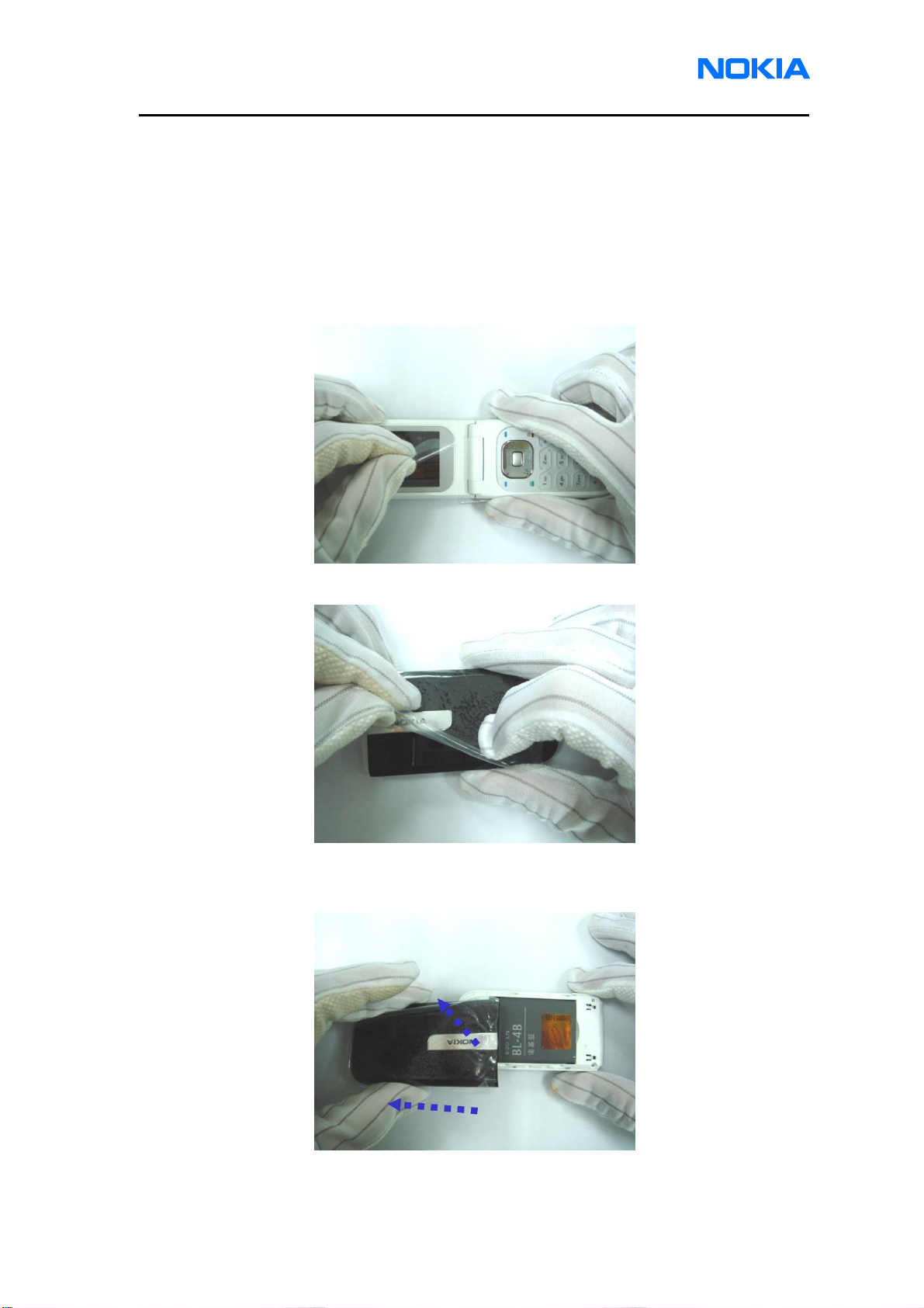
1. Remove Battery Cover (B-cover)
A. Turn the mobile terminal off.
B. Protect the main display surface with a film
C. Protect the A-Cover and Battery Cover surface with a film
D. Force to unsnap of the snaps of battery cover, and slide Battery cover away
from the mobile terminal.
Page 4 © 2007 Nokia Corporation Company Confidential Issue 1 04/2007
Page 5
2505 (RM-307)
Nokia Customer Care Disassembly/Assembly
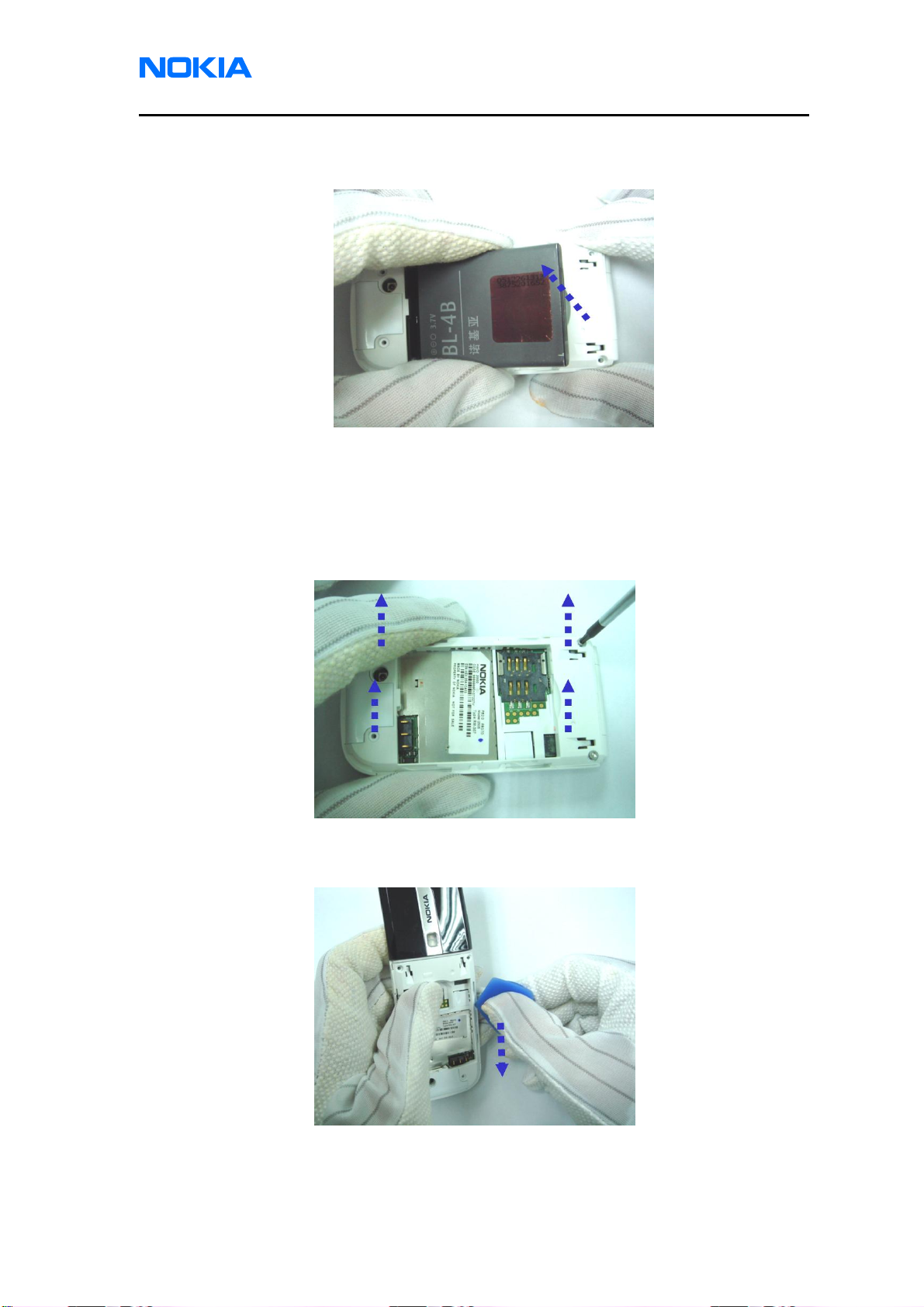
E. Remove battery.
2. Remove D-Cover
A. Use a TORX 5IP screwdriver to loosen and remove the four Torx screws
(T1.4x4). When using torque driver, set torque to 9Ncm @ 450 rpm. The
tolerance is +/-2Ncm.
B. Place the SRT-6 into the gap between C-Cover and D-Cover, move along with
perimeter and lever the snaps to separate C-Cover and D-Cover. (Left Side)
Issue 1 04/2007 © 2007 Nokia Corporation Company Confidential Page 5
Page 6

2505 (RM-307)
Disassembly/Assembly
C. Place the SRT-6 into the gap between C-Cover and D-Cover, move along with
perimeter and lever the snaps to separate C-Cover and D-Cover. (Right Side)
D. Place the SRT-6 into the gap between C-Cover and D-Cover, move along with
perimeter and lever the snaps to separate C-Cover and D-Cover. (Bottom Side)
E. Pull D-Cover away from hook of C-Cover.
Page 6 © 2007 Nokia Corporation Company Confidential Issue 1 04/2007
Page 7

2505 (RM-307)
Nokia Customer Care Disassembly/Assembly
3. Remove Engine Module
A. Use tweezers to clip white paper sticker away from Shielding Frame.
B. Use tweezers to clip FPC Cable connector and pull upward to remove it.
C. Release two hooks of C-Cover and carefully grip both sides of the mobile
terminal and gently pulls out the Engine Module vertically, so as to free it
from C-Cover.
Issue 1 04/2007 © 2007 Nokia Corporation Company Confidential Page 7
Page 8

2505 (RM-307)
Disassembly/Assembly
4. Remove Keymat and C-Cover
A. Press Keymat downward
B. Pull Keymat upward to remove it.
C. Remove C-Cover. Piece parts list.
Page 8 © 2007 Nokia Corporation Company Confidential Issue 1 04/2007
Page 9

2505 (RM-307)
Nokia Customer Care Disassembly/Assembly
5. Remove Earphone Jack
A. Use tweezers to clip Earphone Jack Rubber and pull out it from the D-Cover.
B. Use tweezers to clip Earphone and pull upward to remove it from the D-Cover.
6. Remove Vibrator
A. Use tweezers to clip Vibrator holder and pull upward to remove it from the
D-over.
Issue 1 04/2007 © 2007 Nokia Corporation Company Confidential Page 9
Page 10

2505 (RM-307)
Disassembly/Assembly
B. Use tweezers to clip Vibrator and pull upward to remove it from the D-Cover.
.
7. Remove DC Jack
Use tweezers to clip DC Jack and pull upward to remove it from the D-Cover.
8. Remove A-Cover/B-Cover Assy from C-Cover
A. Use 2mm width “ – ” type screw bit press the hinge inward to remove
A-Cover/B-Cover Assy from the C-Cover.
Page 10 © 2007 Nokia Corporation Company Confidential Issue 1 04/2007
Page 11

2505 (RM-307)
Nokia Customer Care Disassembly/Assembly
B. Pull A-Cover/B-Cover Assy from C-Cover.
C. Pull FPC Cable connector away from C-Cover.
D. Use tweezers to clip Shaft Alloy part away from the hinge hole of C-Cover.
Issue 1 04/2007 © 2007 Nokia Corporation Company Confidential Page 11
Page 12

2505 (RM-307)
Disassembly/Assembly
9. Separate A-Cover from B-Cover
A. Place SRT-6 into the gap between A-Cover and Screw-Cove to remove
Screw-Cover. (Left)
B. Place the SRT-6 into the gap between A-Cover and Screw Cove to remove
Screw Cover. (Right)
C. Use a TORX T5 screwdriver to loosen and remove the Torx screw (M1.4x2).
When using torque driver, set torque to 9 Ncm @ 450 rpm. The tolerance is
+/-2Ncm.
Page 12 © 2007 Nokia Corporation Company Confidential Issue 1 04/2007
Page 13

2505 (RM-307)
Nokia Customer Care Disassembly/Assembly
D. Place SRT-6 into the gap between A-Cover and B-Cover, move along with
perimeter and lever the snaps to separate A-Cover and B-Cover. (Left Side)
E. Place SRT-6 into the gap between A-Cover and B-Cover, move along with
perimeter and lever the snaps to separate A-Cover and B-Cover. (Right Side)
F. Pull A-Cover away from the hook of B-Cover.
Issue 1 04/2007 © 2007 Nokia Corporation Company Confidential Page 13
Page 14

2505 (RM-307)
Disassembly/Assembly
G. Open A-Cover.
10. Remove Button Stopper
Use tweezers to clip Button Stopper away from LCD Module Assy.
11. Remove LCD Module Assy
A. Place SRT-6 into the gap between B-Cover and LCD Module Assy
Page 14 © 2007 Nokia Corporation Company Confidential Issue 1 04/2007
Page 15

2505 (RM-307)
Nokia Customer Care Disassembly/Assembly
B. Pull upward to remove LCD Module Assy.
C. Pull FPC Cable connector away from the hole of B-Cover.
12. Remove Speaker
Use tweezers clip Speaker away from B-Cover.
Issue 1 04/2007 © 2007 Nokia Corporation Company Confidential Page 15
Page 16

2505 (RM-307)
Disassembly/Assembly
Assembly Instructions
To assemble the mobile terminal, follow the “Disassembly Instructions” in reverse
order.
Page 16 © 2007 Nokia Corporation Company Confidential Issue 1 04/2007
 Loading...