

Page 1
CMO Operations & Logistics
Training and Vendor Development
Multimedia Creation & Support
SERVICE MANUAL
Page (14)
CONFIDENTIAL
1
Level 1&2
Approved 1.0
MGR
13.Sep.2007
RM-272
RM-273
Transceiver characteristics:
Band:
-RM-272: Tri-band EDGE phone for EGSM 900/1800/1900MHz
-RM-273: Tri-band EDGE phone for EGSM 850/1800/1900MHz
Camera: 2.0 Megapixel, 8x digital zoom
Display: Active TFT color display with 262.144 colors,
resolution 128 x 160 pixel
Operating System: Series 40
Bluetooth
FM stereo radio
Memory card: microSD
Connector: mini USB Connector, AV Connector
3500c RM-272/RM-273
Transceiver with BL-4c Li-Ion battery pack
Talk time Standby Note
up to 3.5h up to 14.5days
Environmental characteristics:
• Lead-free soldered
Copyright © 2007 NOKIA Corporation. All rights reserved.
Depends on network
parameters
Page 2

Page (14)
CMO Operations & Logistics
Training and Vendor Development
Multimedia Creation & Support CONFIDENTIAL
2
Approved 1.0
MGR
13.Sep.2007
TABLE OF CONTENTS
1.
2.
3.
4.
5.
6.
7.
INTRODUCTION 3
EXPLODED VIEW
LEVEL 2 SOLDER COMPONENTS
SERVICE DEVICES
SW-UPDATE
DISASSEMBLY INSTRUCTION
ASSEMBLY HINTS 1
Page
4
5
6
8
9
3
CHANGE HISTORY
Status Version No. Date Comments
Draft 0.1 07.Sep.2007 Initial draft
Approved 1.0 13.Sep.2007 Approval
3500c RM-272/RM-273
Copyright © 2007 NOKIA Corporation. All rights reserved.
Page 3
Page (14)
CMO Operations & Logistics
Training and Vendor Development
Multimedia Creation & Support CONFIDENTIAL
3
Approved 1.0
MGR
13.Sep.2007
INTRODUCTION1.
The purpose of this document is to help NOKIA service levels 1 and 2 workshop technicians to carry out service to
NOKIA products. This Service Manual is to be used only by authorized NOKIA service suppliers, and the content of it is
confidential. Please note that NOKIA provides also other guidance documents (e.g. Service Bulletins) for service suppliers, follow these regularly and comply with the given instructions.
While every endeavor has been made to ensure the accuracy of this document, some errors may exist.
If you find any errors or if you have further suggestions, please notify NOKIA using the address below:
mailto:cc-ts-rc.documentation@nokia.com
Please keep in mind also that this documentation is continuously being updated and modified, so watch always out
for the newest version.
Warnings and Cautions
Please refer to the phone’s user guide for instructions relating to operation, care and maintenance including important safety information. Note also the following:
Warnings:
CARE MUST BE TAKEN ON INSTALLATION IN VEHICLES FITTED WITH ELECTRONIC ENGINE MANAGEMENT SYSTEMS
1.
AND ANTI–SKID BRAKING SYSTEMS. UNDER CERTAIN FAULT CONDITIONS, EMITTED RF ENERGY CAN AFFECT THEIR
OPERATION. IF NECESSARY, CONSULT THE VEHICLE DEALER/MANUFACTURER TO DETERMINE THE IMMUNITY OF VEHICLE ELECTRONIC SYSTEMS TO RF ENERGY.
THE HANDPORTABLE TELEPHONE MUST NOT BE OPERATED IN AREAS LIKELY TO CONTAIN POTENTIALLY EXPLOSIVE
2.
ATMOSPHERES, EG PETROL STATIONS (SERVICE STATIONS), BLASTING AREAS ETC.
OPERATION OF ANY RADIO TRANSMITTING EQUIPMENT, INCLUDING CELLULAR TELEPHONES, MAY INTERFERE WITH
3.
THE FUNCTIONALITY OF INADEQUATELY PROTECTED MEDICAL DEVICES. CONSULT A PHYSICIAN OR THE MANUFACTURER OF THE MEDICAL DEVICE IF YOU HAVE ANY QUESTIONS. OTHER ELECTRONIC EQUIPMENT MAY ALSO BE SUBJECT TO
INTERFERENCE.
Cautions:
1. Servicing and alignment must be undertaken by qualified personnel only.
2. Ensure all work is carried out at an anti–static workstation and that an anti–static wrist strap is worn.
3. Use only approved components as specified in the parts list.
4. Ensure all components, modules screws and insulators are correctly re–fitted after servicing and alignment.
5. Ensure all cables and wires are repositioned correctly.
Electrostatic discharge can easily damage the sensitive components of electronic products.
Therefore every Service Supplier has to take care of all precautions, which are mentioned in the
service level related “Service Partner Requirements”, available on NOKIA Online. Also see ESD
Protection Requirements in this Service Manual.
3500c RM-272/RM-273
Copyright © 2007 NOKIA Corporation. All rights reserved.
Page 4

(14)
Page
CMO Operations & Logistics
Training and Vendor Development
Multimedia Creation & Support CONFIDENTIAL
4
EXPLODED VIEW2.
See corresponding ITEM/CIRCUIT REF in the Spare Parts Service Bulletins on NOL.
Approved 1.0
MGR
13.Sep.2007
3500c RM-272/RM-273
Copyright © 2007 NOKIA Corporation. All rights reserved.
Page 5
Page (14)
CMO Operations & Logistics
Training and Vendor Development
Multimedia Creation & Support CONFIDENTIAL
5
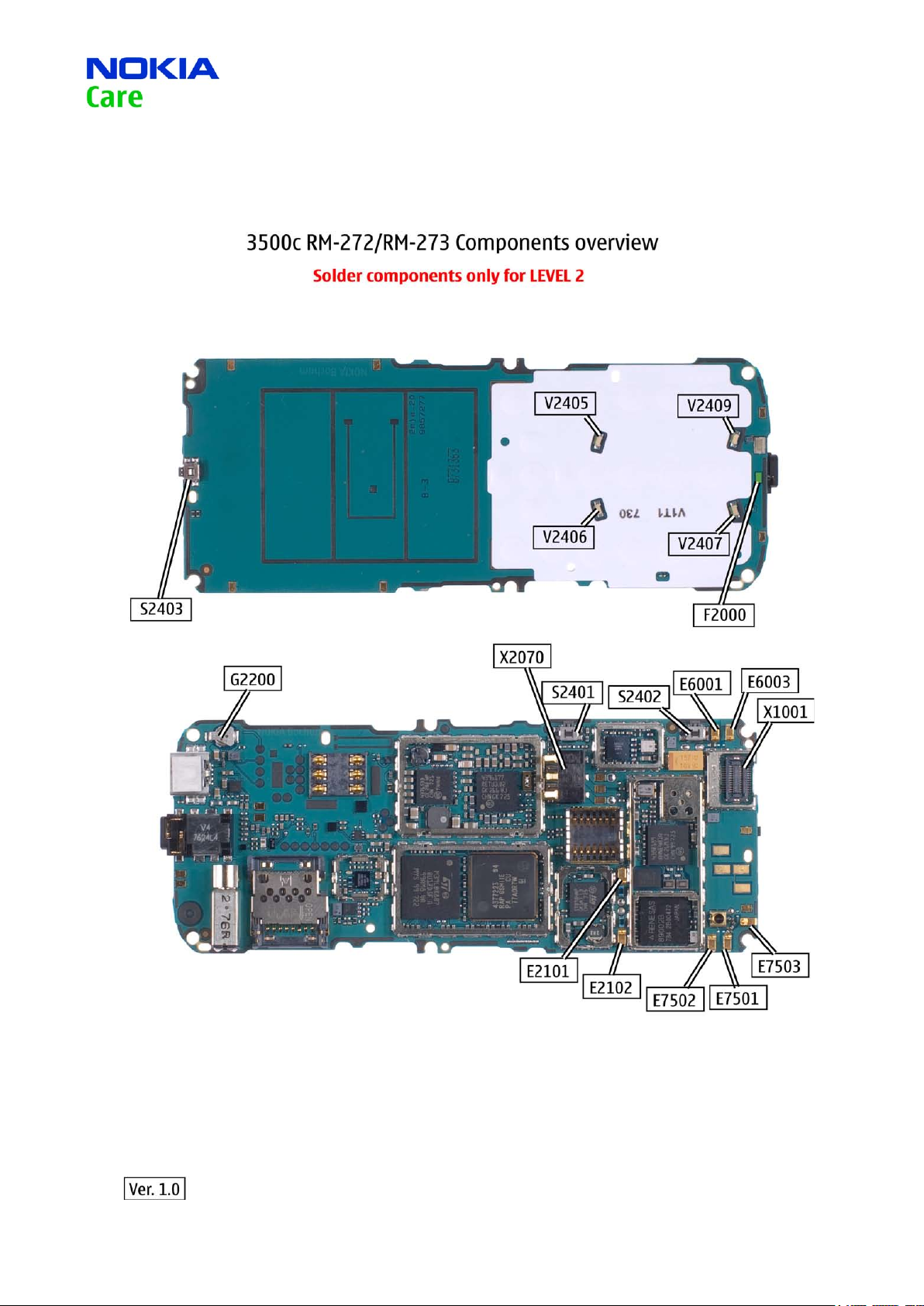
LEVEL 2 SOLDER COMPONENTS3.
Approved 1.0
MGR
13.Sep.2007
3500c RM-272/RM-273
Copyright © 2007 NOKIA Corporation. All rights reserved.
Page 6

Page (14)
CMO Operations & Logistics
Training and Vendor Development
Multimedia Creation & Support CONFIDENTIAL
6
SERVICE DEVICES4.
FLS-5 incl. ACF-8, Driver and User Guide
Dongle and flash device incorporated into one package, developed specifically for POS use.
Approved 1.0
MGR
13.Sep.2007
ACF-8
Universal Power Supply is used to power FLS-4S.
Travel Charger AC-4
Small and lightweight charger for fast charging of your phone
battery.
Internal Battery BL-4c
Inserted under the back cover, this Li-Ion battery provides
power in a lightweight package.
SS-45
Camera removal tool.
3500c RM-272/RM-273
DKE-2
Service Cable to connect the PC with the mini USB connector.
Copyright © 2007 NOKIA Corporation. All rights reserved.
Page 7

Page (14)
7
CMO Operations & Logistics
Training and Vendor Development
Multimedia Creation & Support CONFIDENTIAL
RJ-148
Soldering Jig
Lead-free Solder Wire
Mandatory for lead-free products (Level 2 only).
Approved 1.0
MGR
13.Sep.2007
0772040 NMP Standard Toolkit (V2)
For more informations refer to the Service Bulletin (SB-011) on
NOKIA Online.
Supplier or manufacturer contacts for tool re-order can be
found in “Recommended service equipment” document on
NOKIA Online.
3500c RM-272/RM-273
Copyright © 2007 NOKIA Corporation. All rights reserved.
Page 8

Page (14)
CMO Operations & Logistics
Training and Vendor Development
Multimedia Creation & Support CONFIDENTIAL
8
Approved 1.0
13.Sep.2007
SW-UPDATE5.
Flash Concept – (Point of Sales)
To use FLS-5 Flash Dongle you have to follow the user guide inside the sales package. Please check always for the
latest version of flash software, which is available on
NOKIA Online.
MGR
3500c RM-272/RM-273
Copyright © 2007 NOKIA Corporation. All rights reserved.
Page 9

Page
9
CMO Operations & Logistics
Training and Vendor Development
Multimedia Creation & Support CONFIDENTIAL
DISASSEMBLY INSTRUCTION 6.
(14)
Approved 1.0
MGR
13.Sep.2007
1. Nokia 3500 Classic, disassembly.
3. Unlock and remove the C-COVER.
2. You will need the Nokia Standard Toolkit version 2 and the
camera removal tool SS-45. Also refer to the General Mechanical
Guideline Video for additional hints about the tools and
component handling.
4. Note! Before disassembling the phone, make sure that
the cards are removed. Undo both screws in the order shown
and discard them.
5. Unlock the plastic clips and remove the A-COVER.
3500c RM-272/RM-273
6. Take care to the spring contacts of the A-COVER. Remove the
KEYMAT.
Copyright © 2007 NOKIA Corporation. All rights reserved.
Page 10

Page
10
CMO Operations & Logistics
Training and Vendor Development
Multimedia Creation & Support CONFIDENTIAL
(14)
Approved 1.0
MGR
13.Sep.2007
7. Unscrew the four screws in the order shown.
9. Lift a bit the PWB and remove the USB DOOR.
8. Remove the CONNECTOR COVER.
10. Remove the PWB with DISPLAY from the B-COVER.
11. Take special care to the spring contacts of the PWB.
Remember the correct position of the CAMERA GASKET when
replacing.
3500c RM-272/RM-273
12. Unlock and remove the CAMERA with the SS-45.
Copyright © 2007 NOKIA Corporation. All rights reserved.
Page 11

Page
11
CMO Operations & Logistics
Training and Vendor Development
Multimedia Creation & Support CONFIDENTIAL
(14)
Approved 1.0
MGR
13.Sep.2007
13. Remove the FLEX SHIELDING LID and discard it.
15. Carefully open the DISPLAY connector.
14. Unlock both metal clips of the UI-SHIELD.
16. Separate the DISPLAY from the UI-SHIELD.
17. Remove the EARPIECE ASSEMBLY. Remember its correct
position when assembling the unit.
3500c RM-272/RM-273
18. Unlock and remove the ANTENNA MODULE ASSY.
Copyright © 2007 NOKIA Corporation. All rights reserved.
Page 12

Page
12
CMO Operations & Logistics
Training and Vendor Development
Multimedia Creation & Support CONFIDENTIAL
(14)
Approved 1.0
MGR
13.Sep.2007
19. DC-JACK and MICROPHONE can be removed easily.
21. Then continue on the other side.
20. First unlock the metal clips of the LABEL COVER ASSY on the
shown side.
22. Now separate the parts as shown. The disassembly procedure
is now nished.
3500c RM-272/RM-273
Copyright © 2007 NOKIA Corporation. All rights reserved.
Page 13

Page
13
CMO Operations & Logistics
Training and Vendor Development
Multimedia Creation & Support CONFIDENTIAL
ASSEMBLY HINTS7.
(14)
Approved 1.0
MGR
13.Sep.2007
1. Nokia 3500 Classic, assembly hints.
3. Always use a new FLEX SHIELDING LID when assembling the
unit.
2. You will need the Nokia Standard Toolkit version 2 and the
camera removal tool SS-88. Also refer to the General Mechanical
Guideline Video for additional hints about the tools and
component handling.
4. Insert the LABEL COVER ASSEMBLY into the B-COVER. The LABEL
COVER ASSEMBLY must always be assembled together with the
corresponding engine module!
5. Place the PWB into the B-COVER ASSY as shown.
3500c RM-272/RM-273
6. Take special care to the power switch when assembling the
unit.
Copyright © 2007 NOKIA Corporation. All rights reserved.
Page 14

Page (14)
14
CMO Operations & Logistics
Training and Vendor Development
Multimedia Creation & Support CONFIDENTIAL
Approved 1.0
MGR
13.Sep.2007
7. Lift a bit the PWB and t the USB DOOR into its place. Check
its correct position.
9. Tighten the screws with a torque of 20Ncm in the order
shown.
8. Fit the CONNECTOR COVER onto the B-COVER.
10. Insert new screws and tighten them with a torque of 20Ncm
in the order shown.
3500c RM-272/RM-273
Copyright © 2007 NOKIA Corporation. All rights reserved.
 Loading...