


Nokia Customer Care
Service Manual
RM-242 (Nokia 5610 XpressMusic; L3&4)
Mobile Terminal
Part No: (Issue 2)
COMPANY CONFIDENTIAL
Copyright © 2007 Nokia. All rights reserved.
Amendment Record Sheet
Amendment Record Sheet
Amendment No Date Inserted By Comments
Issue 1 09/2007 GR
Issue 2 10/2007 LB The following updates have been
made to issue 2:
• The product picture has been
updated to the
chapter (1-5)
• Sections
Main RF characteristics
Product selection
for GSM and WCDMA band phones
and
Environmental conditions
have been moved from the
System module
General information
chapter to the
chapter.
RM-242
Page ii COMPANY CONFIDENTIAL Issue 2
Copyright © 2007 Nokia. All rights reserved.

RM-242
Copyright
Copyright
Copyright © 2007 Nokia. All rights reserved.
Reproduction, transfer, distribution or storage of part or all of the contents in this document in any form
without the prior written permission of Nokia is prohibited.
Nokia, Nokia Connecting People, and Nokia X and Y are trademarks or registered trademarks of Nokia
Corporation. Other product and company names mentioned herein may be trademarks or tradenames of
their respective owners.
Nokia operates a policy of continuous development. Nokia reserves the right to make changes and
improvements to any of the products described in this document without prior notice.
Under no circumstances shall Nokia be responsible for any loss of data or income or any special, incidental,
consequential or indirect damages howsoever caused.
The contents of this document are provided "as is". Except as required by applicable law, no warranties of
any kind, either express or implied, including, but not limited to, the implied warranties of merchantability
and fitness for a particular purpose, are made in relation to the accuracy, reliability or contents of this
document. Nokia reserves the right to revise this document or withdraw it at any time without prior notice.
The availability of particular products may vary by region.
IMPORTANT
This document is intended for use by qualified service personnel only.
Issue 2 COMPANY CONFIDENTIAL Page iii
Copyright © 2007 Nokia. All rights reserved.

RM-242
Warnings and cautions
Warnings and cautions
Warnings
• IF THE DEVICE CAN BE INSTALLED IN A VEHICLE, CARE MUST BE TAKEN ON INSTALLATION IN VEHICLES FITTED
WITH ELECTRONIC ENGINE MANAGEMENT SYSTEMS AND ANTI-SKID BRAKING SYSTEMS. UNDER CERTAIN FAULT
CONDITIONS, EMITTED RF ENERGY CAN AFFECT THEIR OPERATION. IF NECESSARY, CONSULT THE VEHICLE DEALER/
MANUFACTURER TO DETERMINE THE IMMUNITY OF VEHICLE ELECTRONIC SYSTEMS TO RF ENERGY.
• THE PRODUCT MUST NOT BE OPERATED IN AREAS LIKELY TO CONTAIN POTENTIALLY EXPLOSIVE ATMOSPHERES,
FOR EXAMPLE, PETROL STATIONS (SERVICE STATIONS), BLASTING AREAS ETC.
• OPERATION OF ANY RADIO TRANSMITTING EQUIPMENT, INCLUDING CELLULAR TELEPHONES, MAY INTERFERE
WITH THE FUNCTIONALITY OF INADEQUATELY PROTECTED MEDICAL DEVICES. CONSULT A PHYSICIAN OR THE
MANUFACTURER OF THE MEDICAL DEVICE IF YOU HAVE ANY QUESTIONS. OTHER ELECTRONIC EQUIPMENT MAY
ALSO BE SUBJECT TO INTERFERENCE.
• BEFORE MAKING ANY TEST CONNECTIONS, MAKE SURE YOU HAVE SWITCHED OFF ALL EQUIPMENT.
Cautions
• Servicing and alignment must be undertaken by qualified personnel only.
• Ensure all work is carried out at an anti-static workstation and that an anti-static wrist strap is worn.
• Ensure solder, wire, or foreign matter does not enter the telephone as damage may result.
• Use only approved components as specified in the parts list.
• Ensure all components, modules, screws and insulators are correctly re-fitted after servicing and
alignment.
• Ensure all cables and wires are repositioned correctly.
• Never test a mobile phone WCDMA transmitter with full Tx power, if there is no possibility to perform the
measurements in a good performance RF-shielded room. Even low power WCDMA transmitters may disturb
nearby WCDMA networks and cause problems to 3G cellular phone communication in a wide area.
• During testing never activate the GSM or WCDMA transmitter without a proper antenna load, otherwise
GSM or WCDMA PA may be damaged.
Page iv COMPANY CONFIDENTIAL Issue 2
Copyright © 2007 Nokia. All rights reserved.

RM-242
For your safety
For your safety
QUALIFIED SERVICE
Only qualified personnel may install or repair phone equipment.
ACCESSORIES AND BATTERIES
Use only approved accessories and batteries. Do not connect incompatible products.
CONNECTING TO OTHER DEVICES
When connecting to any other device, read its user’s guide for detailed safety instructions. Do not connect
incompatible products.
Issue 2 COMPANY CONFIDENTIAL Page v
Copyright © 2007 Nokia. All rights reserved.

RM-242
Care and maintenance
Care and maintenance
This product is of superior design and craftsmanship and should be treated with care. The suggestions below
will help you to fulfil any warranty obligations and to enjoy this product for many years.
• Keep the phone and all its parts and accessories out of the reach of small children.
• Keep the phone dry. Precipitation, humidity and all types of liquids or moisture can contain minerals that
will corrode electronic circuits.
• Do not use or store the phone in dusty, dirty areas. Its moving parts can be damaged.
• Do not store the phone in hot areas. High temperatures can shorten the life of electronic devices, damage
batteries, and warp or melt certain plastics.
• Do not store the phone in cold areas. When it warms up (to its normal temperature), moisture can form
inside, which may damage electronic circuit boards.
• Do not drop, knock or shake the phone. Rough handling can break internal circuit boards.
• Do not use harsh chemicals, cleaning solvents, or strong detergents to clean the phone.
• Do not paint the phone. Paint can clog the moving parts and prevent proper operation.
• Use only the supplied or an approved replacement antenna. Unauthorised antennas, modifications or
attachments could damage the phone and may violate regulations governing radio devices.
All of the above suggestions apply equally to the product, battery, charger or any accessory.
Page vi COMPANY CONFIDENTIAL Issue 2
Copyright © 2007 Nokia. All rights reserved.

RM-242
ESD protection
ESD protection
Nokia requires that service points have sufficient ESD protection (against static electricity) when servicing
the phone.
Any product of which the covers are removed must be handled with ESD protection. The SIM card can be
replaced without ESD protection if the product is otherwise ready for use.
To replace the covers ESD protection must be applied.
All electronic parts of the product are susceptible to ESD. Resistors, too, can be damaged by static electricity
discharge.
All ESD sensitive parts must be packed in metallized protective bags during shipping and handling outside
any ESD Protected Area (EPA).
Every repair action involving opening the product or handling the product components must be done under
ESD protection.
ESD protected spare part packages MUST NOT be opened/closed out of an ESD Protected Area.
For more information and local requirements about ESD protection and ESD Protected Area, contact your local
Nokia After Market Services representative.
Issue 2 COMPANY CONFIDENTIAL Page vii
Copyright © 2007 Nokia. All rights reserved.

RM-242
Battery information
Battery information
Note: A new battery's full performance is achieved only after two or three complete charge and
discharge cycles!
The battery can be charged and discharged hundreds of times but it will eventually wear out. When the
operating time (talk-time and standby time) is noticeably shorter than normal, it is time to buy a new battery.
Use only batteries approved by the phone manufacturer and recharge the battery only with the chargers
approved by the manufacturer. Unplug the charger when not in use. Do not leave the battery connected to
a charger for longer than a week, since overcharging may shorten its lifetime. If left unused a fully charged
battery will discharge itself over time.
Temperature extremes can affect the ability of your battery to charge.
For good operation times with Li-Ion batteries, discharge the battery from time to time by leaving the product
switched on until it turns itself off (or by using the battery discharge facility of any approved accessory
available for the product). Do not attempt to discharge the battery by any other means.
Use the battery only for its intended purpose.
Never use any charger or battery which is damaged.
Do not short-circuit the battery. Accidental short-circuiting can occur when a metallic object (coin, clip or
pen) causes direct connection of the + and - terminals of the battery (metal strips on the battery) for example
when you carry a spare battery in your pocket or purse. Short-circuiting the terminals may damage the battery
or the connecting object.
Leaving the battery in hot or cold places, such as in a closed car in summer or winter conditions, will reduce
the capacity and lifetime of the battery. Always try to keep the battery between 15°C and 25°C (59°F and 77°
F). A phone with a hot or cold battery may temporarily not work, even when the battery is fully charged.
Batteries' performance is particularly limited in temperatures well below freezing.
Do not dispose of batteries in a fire!
Dispose of batteries according to local regulations (e.g. recycling). Do not dispose as household waste.
Page viii COMPANY CONFIDENTIAL Issue 2
Copyright © 2007 Nokia. All rights reserved.

RM-242
Company Policy
Company Policy
Our policy is of continuous development; details of all technical modifications will be included with service
bulletins.
While every endeavour has been made to ensure the accuracy of this document, some errors may exist. If
any errors are found by the reader, NOKIA MOBILE PHONES Business Group should be notified in writing/email.
Please state:
• Title of the Document + Issue Number/Date of publication
• Latest Amendment Number (if applicable)
• Page(s) and/or Figure(s) in error
Please send to:
NOKIA CORPORATION
Nokia Mobile Phones Business Group
Nokia Customer Care
PO Box 86
FIN-24101 SALO
Finland
E-mail: Service.Manuals@nokia.com
Issue 2 COMPANY CONFIDENTIAL Page ix
Copyright © 2007 Nokia. All rights reserved.

RM-242
Company Policy
(This page left intentionally blank.)
Page x COMPANY CONFIDENTIAL Issue 2
Copyright © 2007 Nokia. All rights reserved.

RM-242
Nokia 5610 XpressMusic; L3&4 Service Manual
Structure
Nokia 5610 XpressMusic; L3&4 Service Manual Structure
1 General information
2 Service Devices and Service Concepts
3 BB Troubleshooting and Manual Tuning Guide
4 RF troubleshooting
5 System Module
Glossary
Issue 2 COMPANY CONFIDENTIAL Page xi
Copyright © 2007 Nokia. All rights reserved.

RM-242
Nokia 5610 XpressMusic; L3&4 Service Manual
Structure
(This page left intentionally blank.)
Page xii COMPANY CONFIDENTIAL Issue 2
Copyright © 2007 Nokia. All rights reserved.

Nokia Customer Care
1 — General information
Issue 2 COMPANY CONFIDENTIAL Page 1 –1
Copyright © 2007 Nokia. All rights reserved.

RM-242
General information
(This page left intentionally blank.)
Page 1 –2 COMPANY CONFIDENTIAL Issue 2
Copyright © 2007 Nokia. All rights reserved.

RM-242
General information
Table of Contents
Product selection....................................................................................................................................................1–5
Phone features .......................................................................................................................................................1–5
User interface and software features...................................................................................................................1–6
Accessories..............................................................................................................................................................1–6
Technical specifications.........................................................................................................................................1–7
Main RF characteristics for GSM and WCDMA band phones...........................................................................1–7
General specifications.......................................................................................................................................1–8
Battery endurance.............................................................................................................................................1–8
Environmental conditions ................................................................................................................................1–8
List of Tables
Table 1 Battery and chargers ................................................................................................................................1–6
Table 2 Headsets ....................................................................................................................................................1–7
Table 3 Data cables ................................................................................................................................................1–7
List of Figures
Figure 1 RM-242 (Nokia 5610 XpressMusic) product picture .............................................................................1–5
Issue 2 COMPANY CONFIDENTIAL Page 1 –3
Copyright © 2007 Nokia. All rights reserved.

RM-242
General information
(This page left intentionally blank.)
Page 1 –4 COMPANY CONFIDENTIAL Issue 2
Copyright © 2007 Nokia. All rights reserved.
RM-242
General information
Product selection
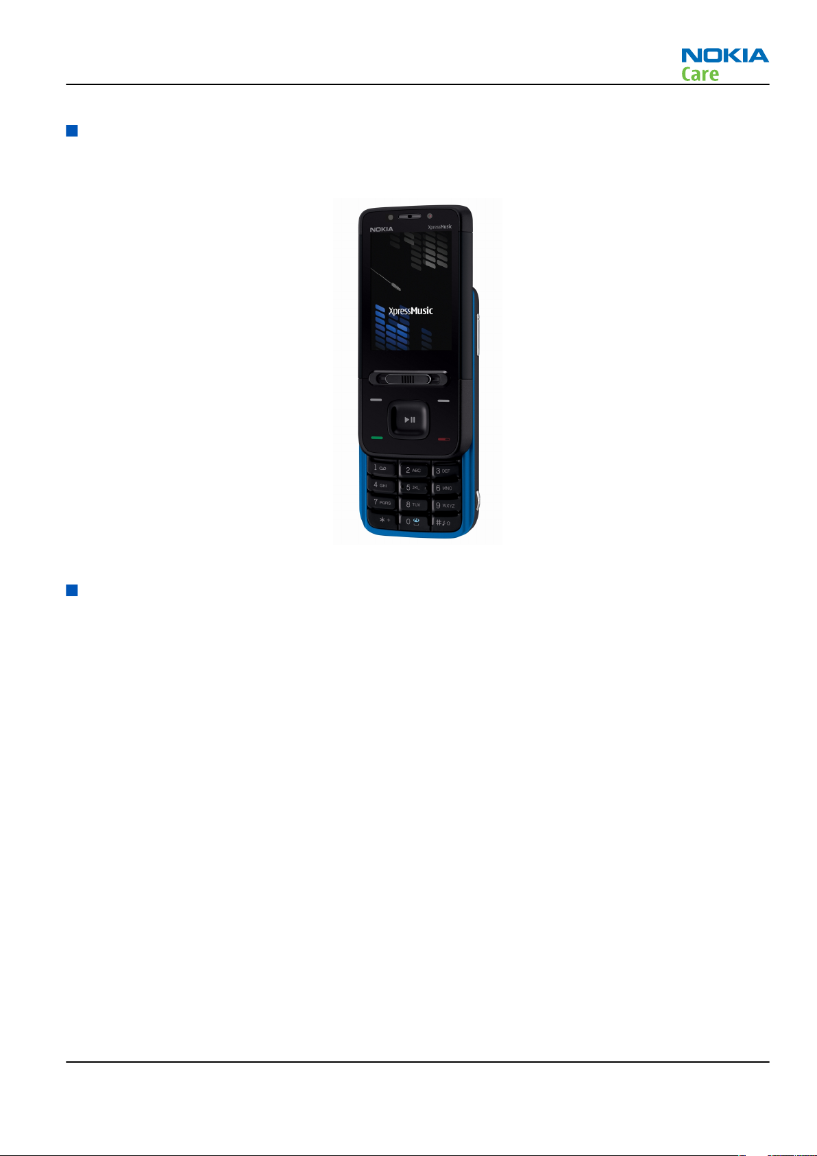
RM-242 (Nokia 5610 XpressMusic) is a WCDMA/GSM dual mode phone, supporting WCDMA 850/2100 bands
and EGSM850/900/1800/1900 bands.
Figure 1 RM-242 (Nokia 5610 XpressMusic) product picture
Phone features
Display and keypad features
• 2.2” 240x320 pixel, 16M colour display (33.5mm x 44.7mm active area)
• Ambient light sensor
• 5-way , navi-key (2 soft-keys, call and end keys)
Hardware features
• 3.2-megapixel auto focus camera with 8x digital zoom and double LED flash
• Secondary camera for video calls
• 2.5mm AV connector for headset
• Micro USB port for data transfer (USB 2.0)
• Bluetooth (version 2.0)
• RDS Stereo radio and music player
• Internal vibrator and antenna
• Plug-in SIM (1.8 V and 3.0 V)
• MicroSD card slot (up to 4GM)
• Two way spring loaded MusicSlider music key
• Side volume keys with zoom functionality
• DAC33 audio ship (for better audio and palyback
Issue 2 COMPANY CONFIDENTIAL Page 1 –5
Copyright © 2007 Nokia. All rights reserved.

RF features
• WCDMA Band I (2100) & V (850)
• GSM/EDGE 850/900/1800/1900
• EDGE: MSC 31
• GPRS: MSC 31
• CSD
User interface and software features
Selection of software applications and services
• Audio messages
• 3GPP streaming / downloading video
• XHTML browsing over TCP/IP
• Themes (wallpapers, icons, colors)
• Music Player supporting MP3, MP4, AAC, ACC+, eAAC+ and WMA
• Nokia Xpress audio messaging (AMS)
• OMA DRM 2.0 (Digital Right Management)
• OMA MMS 1.2, MMS Conformance 3.0, AMR and SMIL
• OMA Client Provisioning v1.1
• Java
• 64 polyphonic ringing tones
• Video ringing tones
• WAP 2.0, XHTML browser over HTTP/TCP/IP stack
• SyncML (local and remote)
• Nokia PC Suite and Nokia Music Manager
RM-242
General information
Accessories
Sales package contents
• Nokia 5610 phone
• Nokia Battery BP-5M
• Nokia Charger: AC-4
• Micro SD memory card: MU-28 or MU-22 (area dependent)
• Nokia wired headset: HS-45 (with Ad56 remote control)
• USB cable CA-101
• CD rom
• User Guide
Table 1 Battery and chargers
Type Name
Note: This phone is charged through the smaller charger Nokia standard interface (2.mm plug). The
standard 3.5mm standard charger can be used together with the CA-44 charger adapter.
Page 1 –6 COMPANY CONFIDENTIAL Issue 2
Copyright © 2007 Nokia. All rights reserved.
RM-242
General information
Type Name
AC-4 Charger
BP-5M Battery 900 mAh Li-Ion
Type Name
Wired
HS-45 Headset (wired)
Type Name
CA-101 Micro USB cable
Table 2 Headsets
Table 3 Data cables
Technical specifications
Main RF characteristics for GSM and WCDMA band phones
Parameter Unit
Cellular system EGSM850/900/1800/1900 + WCDMA band I/V
RX frequency band EGSM850: 869- 894 MHz
EGSM900: 925- 960 MHz
GSM1800: 1805 - 1880 MHz
GSM1900: 1930 - 1990 MHz
WCDMA band I: 2110 - 2170 MHz
WCDMA band V: 869 - 894 MHz
TX frequency band GSM850: 824- 849 MHz
GSM900: 880- 915 MHz
GSM1800: 1710 - 1785 MHz
GSM1900: 1850 - 1910 MHz
WCDMA band I: 1920 - 1980 MHz
WCDMA band V: 824 - 849 MHz
Output power GSM850: +5 ... +33 dBm
EGSM900: +5 … +33 dBm
GSM1800: +0 … +30 dBm
GSM1900: +0 ... +30 dBm
WCDMA band I: -50...+24 dBm
WCDMA band V: -50...+24 dBm
Issue 2 COMPANY CONFIDENTIAL Page 1 –7
Copyright © 2007 Nokia. All rights reserved.
Parameter Unit
Number of RF channels GSM850: 124
EGSM900: 172
GSM1800: 375
GSM1900: 300
WCDMA band I: 277
WCDMA band V: 108
Channel spacing GSM 200 KHz
WCDMA 4.8 MHz
Number of Tx power levels GSM850: 15
GSM900: 15
GSM1800: 16
GSM1900: 16
WCDMA: 75
RM-242
General information
General specifications
Unit Dimension (mm) Weight (g) Volume (cc)
Transceiver with BP-5M
900 mAh Li-Ion battery
pack
111 x 48.5 x 17 111 75
Battery endurance
Battery NMP Talk time NMP Standby time
BP-5M 900 mAh Li-ion Up to 6Hours 13.5 Days
Note: Variation in operation times will occur depending on SIM card, network settings and usage.
Environmental conditions
Environmental
condition
Normal operation
Reduced performance
-15 oC ... +55 oC
55 oC ... +70 oC
Ambient temperature Notes
Specifications fulfilled
Operational only for short periods
Intermittent or no
operation
No operation or
storage
Charging allowed
Page 1 –8 COMPANY CONFIDENTIAL Issue 2
-40 oC ... -15 oC and +70 oC ... +85oC
<-40 oC and >+85 oC
-15 oC ... +55 oC
Copyright © 2007 Nokia. All rights reserved.
Operation not guaranteed but an
attempt to operate will not damage
the phone
No storage. An attempt to operate
may cause permanent damage
RM-242
General information
Environmental
condition
Long term storage
conditions
Humidity and water
resistance
Ambient temperature Notes
0 oC ... +85 oC
Relative humidity range is 5 to 95%.
Condensed or dripping water may
cause intermittent malfunctions.
Protection against dripping water
has to be implemented in (enclosure)
mechanics.
Continuous dampness will cause
permanent damage to the module.
Issue 2 COMPANY CONFIDENTIAL Page 1 –9
Copyright © 2007 Nokia. All rights reserved.

RM-242
General information
(This page left intentionally blank.)
Page 1 –10 COMPANY CONFIDENTIAL Issue 2
Copyright © 2007 Nokia. All rights reserved.

Nokia Customer Care
2 — Service Devices and
Service Concepts
Issue 2 COMPANY CONFIDENTIAL Page 2 –1
Copyright © 2007 Nokia. All rights reserved.

RM-242
Service Devices and Service Concepts
(This page left intentionally blank.)
Page 2 –2 COMPANY CONFIDENTIAL Issue 2
Copyright © 2007 Nokia. All rights reserved.

RM-242
Service Devices and Service Concepts
Table of Contents
Service devices........................................................................................................................................................2–5
Product specific devices....................................................................................................................................2–5
FS-59..............................................................................................................................................................2–5
MJ-136 ...........................................................................................................................................................2–5
RJ-180 ............................................................................................................................................................2–5
SA-149 ...........................................................................................................................................................2–6
General devices..................................................................................................................................................2–6
AC-33..............................................................................................................................................................2–6
ACF-8..............................................................................................................................................................2–6
CU-4................................................................................................................................................................2–7
FLS-4S ............................................................................................................................................................2–8
FLS-5 ..............................................................................................................................................................2–8
FPS-10............................................................................................................................................................2–8
PK-1................................................................................................................................................................2–9
PKD-1 .............................................................................................................................................................2–9
RJ-157 ............................................................................................................................................................2–9
RJ-184 ............................................................................................................................................................2–9
RJ-196 ............................................................................................................................................................2–9
RJ-71 ........................................................................................................................................................... 2–10
RJ-73 ........................................................................................................................................................... 2–10
RJ-93 ........................................................................................................................................................... 2–10
SB-6............................................................................................................................................................. 2–10
SPS-1........................................................................................................................................................... 2–11
SPS-2........................................................................................................................................................... 2–11
SRT-6........................................................................................................................................................... 2–11
SS-46........................................................................................................................................................... 2–11
SS-62........................................................................................................................................................... 2–12
SS-93........................................................................................................................................................... 2–12
ST-26........................................................................................................................................................... 2–12
ST-29........................................................................................................................................................... 2–12
ST-37........................................................................................................................................................... 2–12
ST-40........................................................................................................................................................... 2–13
ST-55........................................................................................................................................................... 2–13
ST-61........................................................................................................................................................... 2–13
SX-4............................................................................................................................................................. 2–13
Cables............................................................................................................................................................... 2–13
CA-28DS ...................................................................................................................................................... 2–14
CA-31D ........................................................................................................................................................ 2–14
CA-35S......................................................................................................................................................... 2–14
CA-89DS ...................................................................................................................................................... 2–15
CA-92U ........................................................................................................................................................ 2–15
DAU-9S........................................................................................................................................................ 2–15
PCS-1........................................................................................................................................................... 2–16
XCS-4........................................................................................................................................................... 2–16
XRS-6........................................................................................................................................................... 2–16
Service concepts .................................................................................................................................................. 2–17
POS (Point of Sale) flash concept .................................................................................................................. 2–17
Flash concept with FPS-10............................................................................................................................. 2–18
CU-4 flash concept with FPS-10..................................................................................................................... 2–19
Module jig service concept............................................................................................................................ 2–20
Issue 2 COMPANY CONFIDENTIAL Page 2 –3
Copyright © 2007 Nokia. All rights reserved.

RM-242
Service Devices and Service Concepts
Module jig MJ-136 set up............................................................................................................................... 2–21
RF testing concept with RF coupler .............................................................................................................. 2–22
Service concept for RF testing and RF/BB tuning........................................................................................ 2–23
List of Figures
Figure 2 POS flash concept ................................................................................................................................. 2–17
Figure 3 Basic flash concept with FPS-10.......................................................................................................... 2–18
Figure 4 CU-4 flash concept with FPS-10........................................................................................................... 2–19
Figure 5 Module jig service concept .................................................................................................................. 2–20
Figure 6 Module jig MJ-136 set up (PWB for RM-240 is used)......................................................................... 2–21
Figure 7 RF testing concept with RF coupler .................................................................................................... 2–22
Figure 8 Service concept for RF testing and RF/BB tuning .............................................................................. 2–23
Page 2 –4 COMPANY CONFIDENTIAL Issue 2
Copyright © 2007 Nokia. All rights reserved.
RM-242
Service Devices and Service Concepts
Service devices
Product specific devices
The table below gives a short overview of service tools that can be used for testing, error analysis and repair
of product RM-242, refer to various concepts.
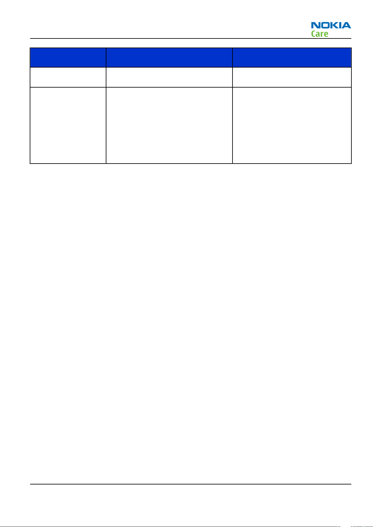
FS-59 Flash adapter
• FS-59 is equipped with a clip interlock system
• provides standardised interface towards Control Unit
• provides RF connection using coupler
• multiplexing between USB and FBUS media, controlled by VUSB
MJ-136 Module jig MJ-136 is meant for component level troubleshooting.
The jig includes an RF interface for GSM, WCDMA and Bluetooth. In
addition, it has the following features:
• Provides mechanical interface with the engine module
• Provides galvanic connection to all needed test pads in module
• Multiplexing between USB and FBUS media, controlled by Vusb
• MMC interface
• Duplicated SIM connector
• Connector for control unit
• Access for AV- and USB connectors
Note: A short user guide is given together with the Module
jig service concept in the end of this chapter.
RJ-180 Rework jig RJ-180 is a jig used for soldering and as a rework jig for the engine
module.
Issue 2 COMPANY CONFIDENTIAL Page 2 –5
Copyright © 2007 Nokia. All rights reserved.
RM-242
Service Devices and Service Concepts
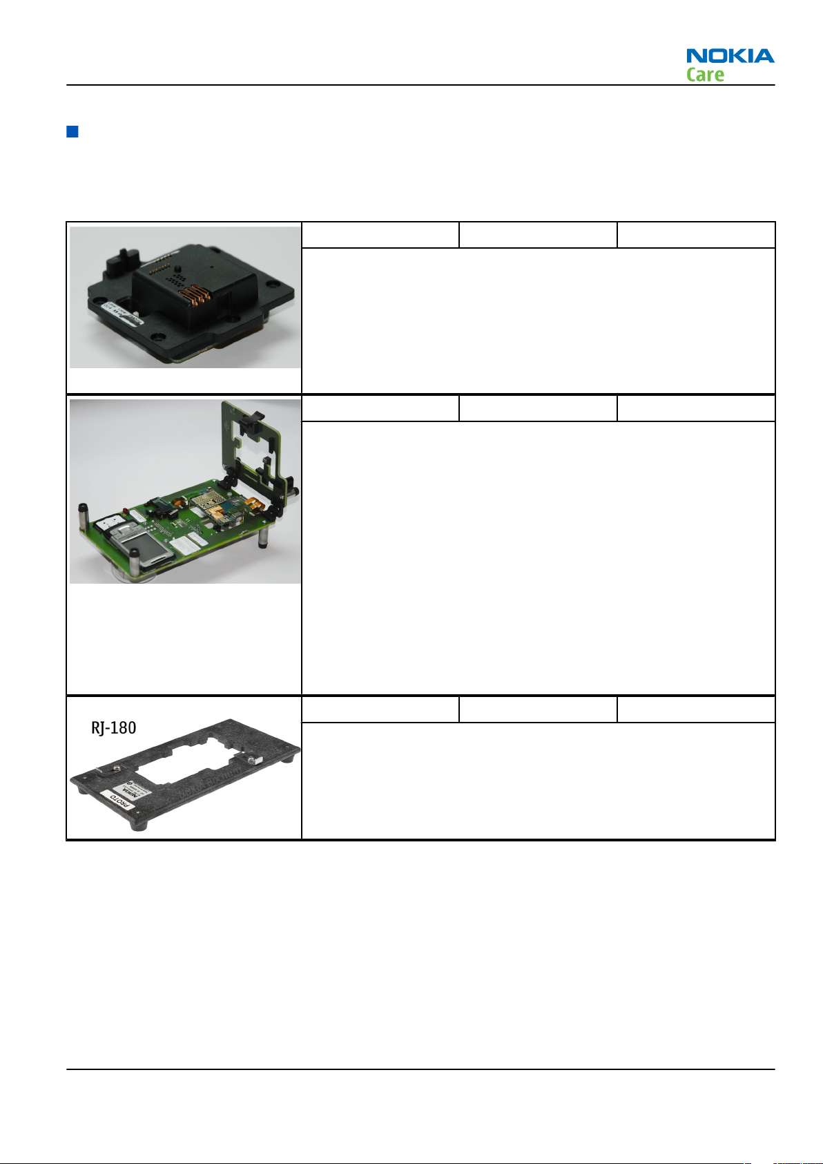
SA-149 RF coupler SA-149 is an RF coupler for WCDMA and GSM RF testing. It is used
together with SS-46 and SS-62.
The following table shows attenuations from the antenna pads of the
mobile terminal to the SMA connectors of SA-149:
•
Frequency Att. (dB)
GSM850 TX Low: 11.5 Mid: 11.4 High: 9.4
GSM850 RX Low: 7.2 Mid: 6.9 High: 6.9
GSM900 TX Low: 6.9 Mid: 7.1 High: 7.3
GSM900 RX Low: 7.1 Mid: 6.9 High: 6.8
GSM1800 TX Low: 6.9 Mid: 7.5 High: 8.2
GSM1800 RX Low: 8.3 Mid: 9.2 High: 9.2
GSM1900 TX Low: 9.3 Mid: 9.2 High: 8.8
GSM1900 RX Low: 8.5 Mid: 8.4 High: 8.4
WCDMA850 TX Low: 11.6 Mid: 11.4 High: 9.7
WCDMA850 RX Low: 7.1 Mid: 6.9 High: 6.9
WCDMA1960 TX Low: 8.6 Mid: 8.4 High: 8.3
WCDMA1900 RX Low: 11.7 Mid: 12.1 High: 11.3
General devices
The table below gives a short overview of service tools that can be used for testing, error analysis and repair
of product RM-242, refer to various concepts.
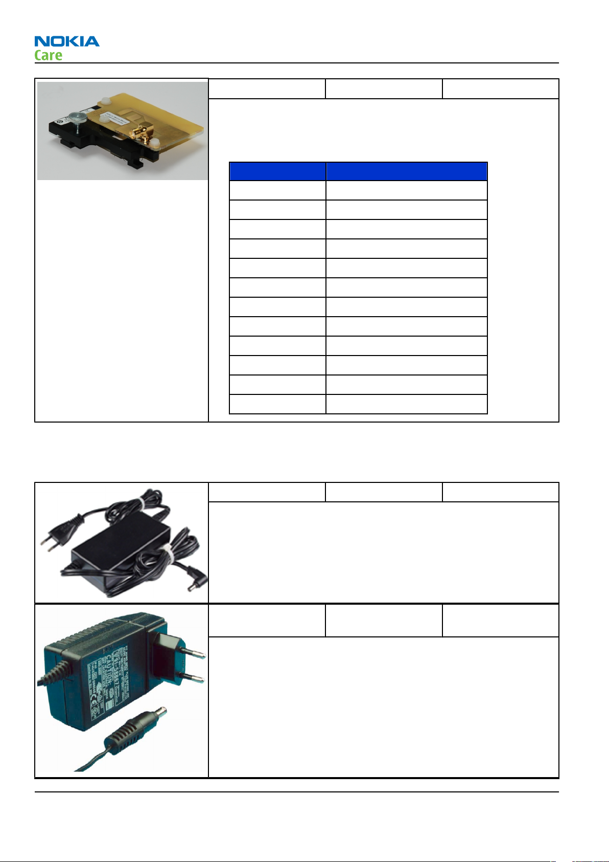
AC-33 Power supply Universal power supply for FPS-10; included in the FPS-10 sales
package.
ACF-8 Universal power
supply
ACF-8 universal power supply is used to power FPS-8. ACF-8 has 6V DC
and 2.1A output.
Page 2 –6 COMPANY CONFIDENTIAL Issue 2
Copyright © 2007 Nokia. All rights reserved.
RM-242
Service Devices and Service Concepts
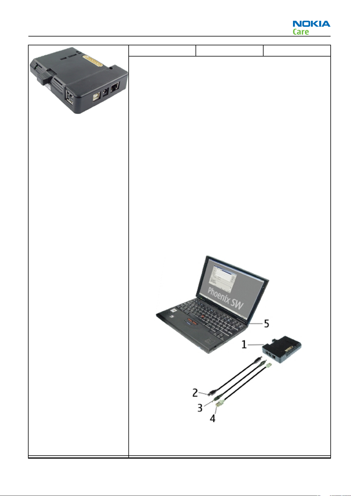
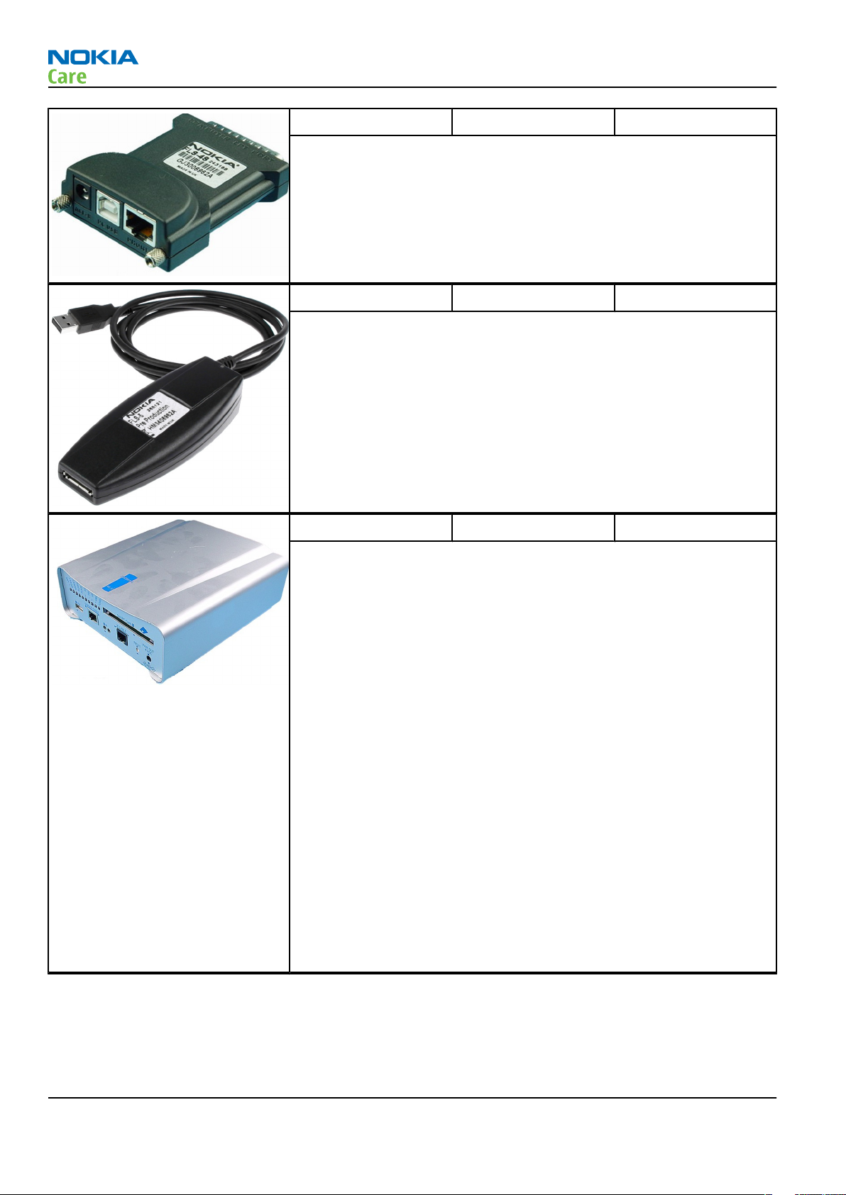
CU-4 Control unit CU-4 is a general service tool used with a module jig and/or a flash
adapter. It requires an external 12 V power supply.
The unit has the following features:
• software controlled via USB
• EM calibration function
• Forwards FBUS/Flashbus traffic to/from terminal
• Forwards USB traffic to/from terminal
• software controlled BSI values
• regulated VBATT voltage
• 2 x USB2.0 connector (Hub)
• FBUS and USB connections supported
When using CU-4, note the special order of connecting cables and
other service equipment:
Instructions
1 Connect a service tool (jig, flash adapter) to CU-4.
2 Connect CU-4 to your PC with a USB cable.
3 Connect supply voltage (12 V)
4 Connect an FBUS cable (if necessary).
5 Start Phoenix service software.
Note: Phoenix enables CU-4 regulators via USB when it is
started.
Reconnecting the power supply requires a Phoenix restart.
Issue 2 COMPANY CONFIDENTIAL Page 2 –7
Copyright © 2007 Nokia. All rights reserved.
RM-242
Service Devices and Service Concepts
FLS-4S Flash device FLS-4S is a dongle and flash device incorporated into one package,
developed specifically for POS use.
FLS-5 Flash device FLS-5 is a dongle and flash device incorporated into one package,
developed specifically for POS use.
Note: FLS-5 can be used as an alternative to PKD-1.
FPS-10 Flash prommer FPS-10 interfaces with:
• PC
• Control unit
• Flash adapter
• Smart card
FPS-10 flash prommer features:
• Flash functionality for BB5 and DCT-4 terminals
• Smart Card reader for SX-2 or SX-4
• USB traffic forwarding
• USB to FBUS/Flashbus conversion
• LAN to FBUS/Flashbus and USB conversion
• Vusb output switchable by PC command
FPS-10 sales package includes:
• FPS-10 prommer
• Power Supply with 5 country specific cords
• USB cable
Note: FPS-21 is substitute FPS-10 if FPS-10 has not been set
up.
Page 2 –8 COMPANY CONFIDENTIAL Issue 2
Copyright © 2007 Nokia. All rights reserved.

RM-242
Service Devices and Service Concepts
PK-1 Software protection
key
PK-1 is a hardware protection key with a USB interface. It has the same
functionality as the PKD-1 series dongle.
PK-1 is meant for use with a PC that does not have a series interface.
To use this USB dongle for security service functions please register
the dongle in the same way as the PKD-1 series dongle.
PKD-1 SW security device
SW security device is a piece of hardware enabling the use of the
service software when connected to the parallel (LPT) port of the PC.
Without the device, it is not possible to use the service software.
Printer or any such device can be connected to the PC through the
device if needed.
RJ-157 Rework jig RJ-157 is a jig used for soldering and as a rework jig for the engine
module. It is used together with the ST-55 stencil.
RJ-184 Rework jig RJ-184 is used as a rework jig for the engine module.
This jig is used in conjunction with the ST-61 stencil for spreading the
soldering paste to the B2201 component.
RJ-196 Rework jig RJ-196 is a rework jig used when servicing the BTHFM (D6000) module.
It is used together with rework stencil ST-37.
Issue 2 COMPANY CONFIDENTIAL Page 2 –9
Copyright © 2007 Nokia. All rights reserved.

Service Devices and Service Concepts
RJ-71 Rework jig RJ-71 is a rework jig used with ST-26 rework stencil.
RJ-73 Rework jig RJ-73 is a rework jig used with ST-29.
RM-242
RJ-93 Rework jig RJ-93 is used as a rework jig for the engine module.
This stencil takes the front end module (FEM) or power amplifier (PA)
module for spreading the soldering paste to the component. Must be
used together with the ST-40 stencil.
SB-6 Bluetooth test and
interface box (sales
package)
The SB-6 test box is a generic service device used to perform Bluetooth
bit error rate (BER) testing, and establishing cordless FBUS connection
via Bluetooth. An ACP-8x charger is needed for BER testing and an
AXS-4 cable in case of cordless interface usage testing .
Sales package includes:
• SB-6 test box
• Installation and warranty information
Page 2 –10 COMPANY CONFIDENTIAL Issue 2
Copyright © 2007 Nokia. All rights reserved.

RM-242
Service Devices and Service Concepts
SPS-1 Soldering Paste
Spreader
The SPS-1 allows spreading of solder to the LGA components pads over
the rework stencils.
SPS-2 Soldering paste
spreader
SRT-6 Opening tool SRT-6 is used to open phone covers.
SS-46 Interface adapter SS-46 acts as an interface adapter between the flash adapter and
FPS-10.
Issue 2 COMPANY CONFIDENTIAL Page 2 –11
Copyright © 2007 Nokia. All rights reserved.

RM-242
Service Devices and Service Concepts
SS-62 Generic flash adapter
base for BB5
• generic base for flash adapters and couplers
• SS-62 equipped with a clip interlock system
• provides standardised interface towards Control Unit
• provides RF connection using galvanic connector or coupler
• multiplexing between USB and FBUS media, controlled by VUSB
SS-93 Opening tool SS-93 is used for opening JAE connectors.
ST-26 Rework stencil ST-26 is a rework stencil used with rework jig RJ-71.
ST-29 rework stencil This stencil is to be used together with RJ-73.
ST-37 BTHFM rework stencil ST-37 stencil is used with the RJ-104 rework jig to service the BTHFM
(D6000) module.
Page 2 –12 COMPANY CONFIDENTIAL Issue 2
Copyright © 2007 Nokia. All rights reserved.

RM-242
Service Devices and Service Concepts
ST-40 Rework stencil ST-40 is a rework stencil and used with RJ-93.
ST-55 Rework stencil ST-55 is a rework stencil used when servicing the Z7540 and Z7541
duplexers. It is used together with the rework jigs RJ-157 and RJ-160.
ST-61 Rework stencil ST-61 is a rework stencil and used with RJ-184.
SX-4 Smart card SX-4 is a BB5 security device used to protect critical features in tuning
and testing.
SX-4 is also needed together with FPS-10 when DCT-4 phones are
flashed.
Cables
The table below gives a short overview of service tools that can be used for testing, error analysis and repair
of product RM-242, refer to various concepts.
Issue 2 COMPANY CONFIDENTIAL Page 2 –13
Copyright © 2007 Nokia. All rights reserved.

RM-242
Service Devices and Service Concepts
CA-28DS Service data cable The CA-28DS service cable is used to connect FLS-4S to the POS flash
adapter for supplying a controlled operating voltage and data
connection.
CA-31D USB cable The CA-31D USB cable is used to connect FPS-10 or FPS-11 to a PC. It is
included in the FPS-10 and FPS-11 sales packages.
CA-35S Power cable CA-35S is a power cable for connecting, for example, the FPS-10 flash
prommer to the Point-Of-Sales (POS) flash adapter.
Page 2 –14 COMPANY CONFIDENTIAL Issue 2
Copyright © 2007 Nokia. All rights reserved.

RM-242
Service Devices and Service Concepts
CA-89DS Cable
CA-92U Video-out cable The CA-92U enables viewing video recordings on a TV screen or
computer monitor. It can also be used while video conferencing.
The cable is used to connect the 2.5mm AV connector of the phone to
the RCA connectors of an AV device.
DAU-9S MBUS cable The MBUS cable DAU-9S has a modular connector and is used, for
example, between the PC's serial port and module jigs, flash adapters
or docking station adapters.
Note: Only ROHS compliant version GM 30083821 allowed.
Note: Docking station adapters valid for DCT4 products.
Issue 2 COMPANY CONFIDENTIAL Page 2 –15
Copyright © 2007 Nokia. All rights reserved.

RM-242
Service Devices and Service Concepts
PCS-1 Power cable The PCS-1 power cable (DC) is used with a docking station, a module
jig or a control unit to supply a controlled voltage.
XCS-4 Modular cable XCS-4 is a shielded (one specially shielded conductor) modular cable
for flashing and service purposes.
XRS-6 RF cable The RF cable is used to connect, for example, a module repair jig to
the RF measurement equipment.
SMA to N-Connector approximately 610 mm.
Attenuation for:
• GSM850/900: 0.3+-0.1 dB
• GSM1800/1900: 0.5+-0.1 dB
• WLAN: 0.6+-0.1dB
Page 2 –16 COMPANY CONFIDENTIAL Issue 2
Copyright © 2007 Nokia. All rights reserved.

RM-242
Service Devices and Service Concepts
Service concepts
POS (Point of Sale) flash concept
Figure 2 POS flash concept
Type Description
Product specific tools
BP-5M Battery
Other tools
FLS-5 POS flash dongle
PC with Phoenix service software
Cables
DKE-2 USB connectivity cable
Issue 2 COMPANY CONFIDENTIAL Page 2 –17
Copyright © 2007 Nokia. All rights reserved.

Flash concept with FPS-10
RM-242
Service Devices and Service Concepts
Figure 3 Basic flash concept with FPS-10
Type Description
Product specific devices
FS-59 Flash adapter
Other devices
FPS-10 Flash prommer box
PKD-1/PK-1 SW security device
SS-46 Interface adapter
PC with Phoenix service software
Cables
XCS-4 Modular cable
CA-35S Power cable
USB cable
Page 2 –18 COMPANY CONFIDENTIAL Issue 2
Copyright © 2007 Nokia. All rights reserved.

RM-242
Service Devices and Service Concepts
CU-4 flash concept with FPS-10
Figure 4 CU-4 flash concept with FPS-10
Type Description
Product specific devices
FS-59 Flash adapter
Other devices
CU-4 Control unit
FPS-10 Flash prommer box
PKD-1/PK-1 SW security device
SS-62 Flash adapter base
SX-4 Smart card
PC with Phoenix service software
Cables
PCS-1 Power cable
XCS-4 Modular cable
Standard USB cable
USB cable
Issue 2 COMPANY CONFIDENTIAL Page 2 –19
Copyright © 2007 Nokia. All rights reserved.
Module jig service concept
RM-242
Service Devices and Service Concepts
Figure 5 Module jig service concept
Type Description
Phone specific devices
MJ-136 Module jig
Other devices
CU-4 Control unit
FPS-10 Flash prommer box
PK-1 SW security device
SX-4 Smart card
PC with VPOS and Phoenix service software
Measurement equipment
Cables
PCS-1 DC power cable
XCS-4 Modular cable
XRF-1 RF cable
USB cable
Page 2 –20 COMPANY CONFIDENTIAL Issue 2
Copyright © 2007 Nokia. All rights reserved.

RM-242
Service Devices and Service Concepts
Type Description
GPIB control cable
Module jig MJ-136 set up
Figure 6 Module jig MJ-136 set up (PWB for RM-240 is used)
1 Remove the PWB, antenna IHF assembly, bottom keymat assembly and bottom flex from the phone.
2 Fit the PWB according to illustration above and connect the top flex connector.
3 Fit the antenna IHF assembly and lock it.
4 Close the supporting frame of the jig over the PWB.
5 Pass the bottom flex connector through the lid in the jig and connect it on the backside of the jig.
6 Fit the bottom flex to the jig by using 2 screws and place the bottom keymat on top.
7 Pass the top flex connector through the jig and connect it on the back side.
8 Put the phone upper part in place on the jig.
Issue 2 COMPANY CONFIDENTIAL Page 2 –21
Copyright © 2007 Nokia. All rights reserved.

RF testing concept with RF coupler
RM-242
Service Devices and Service Concepts
Figure 7 RF testing concept with RF coupler
Type Description
Product specific devices
FS-59 Flash adapter
SA-149 RF coupler
Other devices
CU-4 Control unit
SX-4 Smart card
FPS-10 Flash prommer box
PKD-1/PK-1 SW security device
SS-62 Flash adapter base
Measurement equipment
PC with Phoenix service software
Cables
PCS-1 Power cable
XCS-4 Modular cable
XRS-6 RF cable
Page 2 –22 COMPANY CONFIDENTIAL Issue 2
Copyright © 2007 Nokia. All rights reserved.

RM-242
Service Devices and Service Concepts
Type Description
GPIB control cable
USB cable
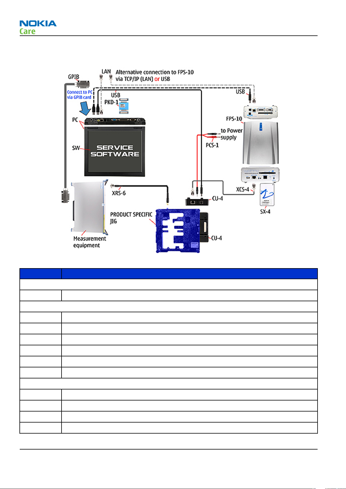
Service concept for RF testing and RF/BB tuning
Figure 8 Service concept for RF testing and RF/BB tuning
Type Description
Product specific devices
MJ-136 Module jig
Other devices
CU-4 Control unit
PK-1 SW security device
SX-4 Smart card
Measurement equipment
Smart card reader
PC with Phoenix service software
Cables
DAU-9S MBUS cable
Issue 2 COMPANY CONFIDENTIAL Page 2 –23
Copyright © 2007 Nokia. All rights reserved.

Type Description
PCS-1 DC power cable
XRS-6 RF cable
GPIB control cable
USB cable
RM-242
Service Devices and Service Concepts
Page 2 –24 COMPANY CONFIDENTIAL Issue 2
Copyright © 2007 Nokia. All rights reserved.

Nokia Customer Care
3 — BB Troubleshooting and
Manual Tuning Guide
Issue 2 COMPANY CONFIDENTIAL Page 3 –1
Copyright © 2007 Nokia. All rights reserved.

RM-242
BB Troubleshooting and Manual Tuning Guide
(This page left intentionally blank.)
Page 3 –2 COMPANY CONFIDENTIAL Issue 2
Copyright © 2007 Nokia. All rights reserved.

RM-242
BB Troubleshooting and Manual Tuning Guide
Table of Contents
Baseband self tests in Phoenix .............................................................................................................................3–5
Power and charging troubleshooting..................................................................................................................3–7
Dead or jammed device troubleshooting.......................................................................................................3–7
General power checking...................................................................................................................................3–9
Charging troubleshooting ............................................................................................................................. 3–11
Interface troubleshooting .................................................................................................................................. 3–12
Flash programming fault troubleshooting.................................................................................................. 3–12
Combo memory troubleshooting ................................................................................................................. 3–15
SD card troubleshooting................................................................................................................................ 3–15
USB interface troubleshooting...................................................................................................................... 3–16
SIM card troubleshooting .............................................................................................................................. 3–17
User interface troubleshooting.......................................................................................................................... 3–19
Keypad and side keys troubleshooting........................................................................................................ 3–19
Display module troubleshooting.................................................................................................................. 3–21
General instructions for display troubleshooting.................................................................................. 3–21
Display troubleshooting ........................................................................................................................... 3–22
Display backlight troubleshooting .......................................................................................................... 3–24
Camera module troubleshooting....................................................................................................................... 3–26
Introduction to camera troubleshooting .................................................................................................... 3–26
Back (main) camera troubleshooting .......................................................................................................... 3–26
Taking and evaluating test pictures with main camera ....................................................................... 3–26
Camera hardware troubleshooting......................................................................................................... 3–27
Camera hardware troubleshooting......................................................................................................... 3–27
Small (front) camera troubleshooting ......................................................................................................... 3–29
Evaluating videocall picture quality from small (front) camera........................................................... 3–29
Small (front) camera bad image quality troubleshooting.................................................................... 3–30
Small (front) camera troubleshooting .................................................................................................... 3–30
Small (front) camera hardware troubleshooting .................................................................................. 3–32
LED camera flash troubleshooting................................................................................................................ 3–33
Audio troubleshooting........................................................................................................................................ 3–33
Audio troubleshooting test instructions...................................................................................................... 3–33
Internal earpiece troubleshooting ............................................................................................................... 3–38
Internal microphone troubleshooting......................................................................................................... 3–38
Internal handsfree (IHF) troubleshooting.................................................................................................... 3–40
External earpiece troubleshooting............................................................................................................... 3–40
Vibra troubleshooting.................................................................................................................................... 3–42
Baseband manual tuning guide......................................................................................................................... 3–42
Certificate restoring for BB5 products.......................................................................................................... 3–42
Energy management calibration.................................................................................................................. 3–48
List of Tables
Table 4 Display module troubleshooting cases................................................................................................ 3–21
Table 5 Pixel defects ........................................................................................................................................... 3–22
Table 6 Calibration value limits ......................................................................................................................... 3–48
List of Figures
Figure 9 Flashing pic 1. Take single trig measurement for the rise of the BSI signal.................................. 3–13
Figure 10 Flashing pic 2. Take single trig measurement for the rise of the BSI signal................................ 3–14
Issue 2 COMPANY CONFIDENTIAL Page 3 –3
Copyright © 2007 Nokia. All rights reserved.

BB Troubleshooting and Manual Tuning Guide
Figure 11 Single-ended output waveform of the Ext_in_HP_out measurement when earpiece is
connected. ................................................................................................................................................. 3–36
Figure 12 Differential output waveform of the Ext_in_IHF_out out loop measurement when speaker is
connected. ................................................................................................................................................. 3–36
Figure 13 Single-ended output waveform of the HP_in_Ext_out loop when microphone is connected....
3–37
RM-242
Page 3 –4 COMPANY CONFIDENTIAL Issue 2
Copyright © 2007 Nokia. All rights reserved.

RM-242
BB Troubleshooting and Manual Tuning Guide
Baseband self tests in Phoenix
Context
Always start the troubleshooting procedure by running the Phoenix self tests. If a test fails, please follow the
diagram below.
If the phone is dead and you cannot perform the self tests, go to
Dead or jammed device troubleshooting.
Issue 2 COMPANY CONFIDENTIAL Page 3 –5
Copyright © 2007 Nokia. All rights reserved.

Troubleshooting flow
RM-242
BB Troubleshooting and Manual Tuning Guide
Page 3 –6 COMPANY CONFIDENTIAL Issue 2
Copyright © 2007 Nokia. All rights reserved.

RM-242
BB Troubleshooting and Manual Tuning Guide
Power and charging troubleshooting
Dead or jammed device troubleshooting
Troubleshooting flow
Issue 2 COMPANY CONFIDENTIAL Page 3 –7
Copyright © 2007 Nokia. All rights reserved.

Troubleshooting flow
RM-242
BB Troubleshooting and Manual Tuning Guide
Page 3 –8 COMPANY CONFIDENTIAL Issue 2
Copyright © 2007 Nokia. All rights reserved.

RM-242
BB Troubleshooting and Manual Tuning Guide
General power checking
Check the following voltages:
Signal name Regulator Sleep Idle Nominal
voltage
VIO AVILMA ON ON 1.82 Memory, I/Os,
VBACK AVILMA ON ON 2.5 Back-up
VSIM1 AVILMA ON ON 1.8/3.0 SIM card
VDRAM AVILMA ON ON 1.82 SDRAM
VAUX AVILMA OFF OFF 2.5 Hall sensor
VANA AVILMA ON ON 2.5 Audio, some
VR1 AVILMA OFF ON 2.5 Crystal
VRFC AVILMA OFF ON 1.8 RAP converters
VRCP1 AVILMA 4.75 To RF parts RF active
VREF AVILMA ON ON 1.35 RF reference
VCORE BETTY ON ON 1.05
1.25
1.35
1.40
Main user Notes
Display
battery
display
pull-ups
oscillators
RAP digital
VOUT BETTY OFF OFF 2.5 Analogue
switch
VCAM_2V8 LP3987ITLX-2.
85/N3300
VCAM_1V8 LM3677TLX-1.
82/L3300
VCAM_1V3 LP5952TLX-1.
3/L3403
VSD LP3928TLX-18
28/Z4800
VLEDOUT TPS61061/
N2301
VDAC LP3985-3/
N2006
VLED TPS75105/
N2401
Issue 2 COMPANY CONFIDENTIAL Page 3 –9
OFF OFF 2.850 Camera Disabled in
OFF OFF 1.800 Camera Disabled in
OFF OFF 1.3 Camera Disabled in
OFF OFF 2.850 MMC/SD card Disabled in
OFF OFF 14.5 LCD Backlight Disabled in
OFF OFF 3.0 DAC-33 Disabled in
OFF OFF 4.0 Keyboard
backlight
Copyright © 2007 Nokia. All rights reserved.
Accessory
connected
sleep
sleep
sleep
sleep
sleep
sleep
Disabled in
sleep

RM-242
BB Troubleshooting and Manual Tuning Guide
Signal name Regulator Sleep Idle Nominal
voltage
VRGB LP5521/
N2440
OFF OFF 4.0 Keyboard
Main user Notes
Disabled in
backlight
sleep
Page 3 –10 COMPANY CONFIDENTIAL Issue 2
Copyright © 2007 Nokia. All rights reserved.

RM-242
BB Troubleshooting and Manual Tuning Guide
Charging troubleshooting
Troubleshooting flow
Issue 2 COMPANY CONFIDENTIAL Page 3 –11
Copyright © 2007 Nokia. All rights reserved.

Interface troubleshooting
Flash programming fault troubleshooting
Part 1
RM-242
BB Troubleshooting and Manual Tuning Guide
Page 3 –12 COMPANY CONFIDENTIAL Issue 2
Copyright © 2007 Nokia. All rights reserved.

RM-242
BB Troubleshooting and Manual Tuning Guide
Part 2
Figure 9 Flashing pic 1. Take single trig measurement for the rise of the BSI signal.
Issue 2 COMPANY CONFIDENTIAL Page 3 –13
Copyright © 2007 Nokia. All rights reserved.

BB Troubleshooting and Manual Tuning Guide
Figure 10 Flashing pic 2. Take single trig measurement for the rise of the BSI signal.
RM-242
Page 3 –14 COMPANY CONFIDENTIAL Issue 2
Copyright © 2007 Nokia. All rights reserved.

RM-242
BB Troubleshooting and Manual Tuning Guide
Combo memory troubleshooting
Troubleshooting flow
Issue 2 COMPANY CONFIDENTIAL Page 3 –15
Copyright © 2007 Nokia. All rights reserved.

SD card troubleshooting
Troubleshooting flow
RM-242
BB Troubleshooting and Manual Tuning Guide
Page 3 –16 COMPANY CONFIDENTIAL Issue 2
Copyright © 2007 Nokia. All rights reserved.

RM-242
BB Troubleshooting and Manual Tuning Guide
USB interface troubleshooting
Troubleshooting flow
Issue 2 COMPANY CONFIDENTIAL Page 3 –17
Copyright © 2007 Nokia. All rights reserved.

SIM card troubleshooting
Troubleshooting flow
RM-242
BB Troubleshooting and Manual Tuning Guide
Page 3 –18 COMPANY CONFIDENTIAL Issue 2
Copyright © 2007 Nokia. All rights reserved.

RM-242
BB Troubleshooting and Manual Tuning Guide
User interface troubleshooting
Keypad and side keys troubleshooting
Context
There are two possible failure modes in the keyboard module:
• One or more keys are stuck, so that the key does not react when a keydome or a side key is pressed. This
kind of failure is caused by mechanical reasons (dirt, rust, mechanical damage, etc.)
• Malfunction of several keys at the same time; this happens when one or more rows or columns in the key
matrix are failing (shortcut or open connection).
If the failure mode is not clear, start with the Keyboard test in Phoenix.
Numeric keypad troubleshooting
Issue 2 COMPANY CONFIDENTIAL Page 3 –19
Copyright © 2007 Nokia. All rights reserved.

Top keypad troubleshooting
RM-242
BB Troubleshooting and Manual Tuning Guide
Page 3 –20 COMPANY CONFIDENTIAL Issue 2
Copyright © 2007 Nokia. All rights reserved.

RM-242
BB Troubleshooting and Manual Tuning Guide
Side keys troubleshooting
Display module troubleshooting
General instructions for display troubleshooting
Context
• The display is in a normal mode when the phone is in active use.
• Display is in a partial idle mode when the phone is in the screen saver mode.
• The operating modes of the display can be controlled with the help of
Table 4 Display module troubleshooting cases
Display blank There is no image on the display. The display looks
the same when the phone is on as it does when the
phone is off. The backlight can be on in some cases.
Image on the display not correct Image on the display can be corrupted or a part of
the image can be missing. If a part of the image is
missing, change the display module. If the image is
otherwise corrupted, follow the appropriate
troubleshooting diagram.
Issue 2 COMPANY CONFIDENTIAL Page 3 –21
Copyright © 2007 Nokia. All rights reserved.
Phoenix
.

RM-242
BB Troubleshooting and Manual Tuning Guide
Backlight dim or not working at all Backlight LED components are inside the display
module. Backlight failure can also be in the
connector or in the backlight power source in the
main engine of the phone.
This means that in case the display is working
(image OK), the backlight is faulty.
Visual defects (pixel) Pixel defects can be checked by controlling the
display with Phoenix. Use both colours, black and
white, on a full screen.
The display may have some random pixel defects
that are acceptable for this type of display. The
criteria when pixel defects are regarded as a display
failure, resulting in a replacement of the display, are
presented the following table.
Table 5 Pixel defects
Item White dot defect Black dot
defect
1 Defect counts R G B White Dot
Total
1 1 1 1
2 Combined
defect counts
Not allowed.
Two single dot defects that are within 5 mm of each other should be
interpreted as combined dot defect.
1 1
Total
Steps
1. Verify with a working display that the fault is not on the display module itself.
The display module cannot be repaired.
2. Check that the cellular engine is working normally.
i To check the functionality, connect the phone to a docking station.
ii Start
iii Read the phone information to check that also the application engine is functioning normally (you
3. Proceed to the display troubleshooting flowcharts.
Use the Display Test tool in
Phoenix
should be able to read the APE ID).
service software.
Phoenix
to find the detailed fault mode.
Display troubleshooting
Context
There are three different display fault cases;
1 No backlights when image is on
2 No image when backlight is on
3 No backlight and no image
Page 3 –22 COMPANY CONFIDENTIAL Issue 2
Copyright © 2007 Nokia. All rights reserved.

RM-242
BB Troubleshooting and Manual Tuning Guide
Note: When assembling/disassembling the phone, all grounding contacts between different levels
(display, display flex, display frame, BTBl connector) must be checked in order to have them properly
connected.
Issue 2 COMPANY CONFIDENTIAL Page 3 –23
Copyright © 2007 Nokia. All rights reserved.

Troubleshooting flow
RM-242
BB Troubleshooting and Manual Tuning Guide
Page 3 –24 COMPANY CONFIDENTIAL Issue 2
Copyright © 2007 Nokia. All rights reserved.

RM-242
BB Troubleshooting and Manual Tuning Guide
Display backlight troubleshooting
Troubleshooting flow
Issue 2 COMPANY CONFIDENTIAL Page 3 –25
Copyright © 2007 Nokia. All rights reserved.

RM-242
BB Troubleshooting and Manual Tuning Guide
Camera module troubleshooting
Introduction to camera troubleshooting
Bad conditions often cause bad pictures. Therefore, the camera operation has to be checked in constant
conditions or by using a second, known-to-be-good Nokia device as reference. Image quality is hard to
measure quantitatively, and the difference between a good and a bad picture can be small. Some training
or experience may be needed to detect what is actually wrong.
When checking for possible errors in camera functionality, knowing what error is suspected significantly
helps the testing by narrowing down the amount of test cases. The following types of image quality problems
are common:
• Dust (black spots)
• Lack of sharpness
• Bit errors
Back (main) camera troubleshooting
Taking and evaluating test pictures with main camera
When
• Avoid bright fluorescent light, 50/60Hz electrical network or high artificial illumination levels
• If the phone is hot, let it rest for a while before taking the picture
• Make sure the optical system is clean
• Use highest possible resolution
• Make sure the light is sufficient (bright office lightning)
• Do not take the picture towards light source
• Hold the phone as still as possible when taking the picture
• Pictures should be taken both at infinity ~>2m and at macro distance ~10-15 cm in order to verify auto
When
• The center of the picture is sharper than the edges
• If phone has auto focus: Remember that the white focussing frame which appears when the camera button
• The image may be blurred, though it does not show in the viewfinder
• Analyse the picture from your PC monitor, full colour setting is recommended
• If possible, compare with a picture of the same motive taken with a similar Nokia device
taking
focus functionality
evaluating
is pressed halfway down, must turn green for auto focus lock. If the frame turns red, the camera is not
focussed!
a test picture, remember the following:
a test picture, remember the following:
Page 3 –26 COMPANY CONFIDENTIAL Issue 2
Copyright © 2007 Nokia. All rights reserved.

RM-242
BB Troubleshooting and Manual Tuning Guide
Camera hardware troubleshooting
Troubleshooting flow
Issue 2 COMPANY CONFIDENTIAL Page 3 –27
Copyright © 2007 Nokia. All rights reserved.

Camera hardware troubleshooting
Troubleshooting flow
RM-242
BB Troubleshooting and Manual Tuning Guide
Page 3 –28 COMPANY CONFIDENTIAL Issue 2
Copyright © 2007 Nokia. All rights reserved.

RM-242
BB Troubleshooting and Manual Tuning Guide
Small (front) camera troubleshooting
Evaluating videocall picture quality from small (front) camera
When testing the picture quality of a videocall, remember the following:
• Avoid bright fluorescent light, 50/60Hz electrical network or high artificial illumination levels
• Make sure the optical system is clean
• Make sure the light is suffiecient (bright office lightning)
• Do not take the picture towards light source
• Hold the phone as still as possible when evaluating the video call image quality.
• Distance should be approximately 40 cm
When
• The center of the picture is sharper than the edges
• If possible, compare with the picture on another Nokia device in a videocall, and of the same motive.
evaluating
Note: Always use the "troubled" phone when evaluating a picture in a video call (top right corner
of display). Do not evaluate the picture on the receiving phone.
the picture quality of a video call, remember the following:
Issue 2 COMPANY CONFIDENTIAL Page 3 –29
Copyright © 2007 Nokia. All rights reserved.

BB Troubleshooting and Manual Tuning Guide
Small (front) camera bad image quality troubleshooting
Troubleshooting flow
RM-242
Page 3 –30 COMPANY CONFIDENTIAL Issue 2
Copyright © 2007 Nokia. All rights reserved.

RM-242
BB Troubleshooting and Manual Tuning Guide
Small (front) camera troubleshooting
Troubleshooting flow
Issue 2 COMPANY CONFIDENTIAL Page 3 –31
Copyright © 2007 Nokia. All rights reserved.

Small (front) camera hardware troubleshooting
Troubleshooting flow
RM-242
BB Troubleshooting and Manual Tuning Guide
Page 3 –32 COMPANY CONFIDENTIAL Issue 2
Copyright © 2007 Nokia. All rights reserved.

RM-242
BB Troubleshooting and Manual Tuning Guide
LED camera flash troubleshooting
Troubleshooting flow
Audio troubleshooting
Audio troubleshooting test instructions
Differential external earpiece and internal earpiece outputs can be measured either with a single-ended or
a differential probe.
When measuring with a single-ended probe each output is measured against the ground.
Internal handsfree output is measured using a current probe, if a special low-pass filter designed for
measuring a digital amplifier is not available. Note also that when using a current probe, the input signal
frequency must be set to 2kHz.
The input signal for each loop test can be either single-ended or differential.
Required equipment
The following equipment is needed for the tests:
Issue 2 COMPANY CONFIDENTIAL Page 3 –33
Copyright © 2007 Nokia. All rights reserved.

RM-242
BB Troubleshooting and Manual Tuning Guide
• Oscilloscope
• Function generator (sine waveform)
• 'Active speaker' or 'speaker and power amplifier'
• Sound level meter
• Current probe (Internal handsfree DPMA output measurement)
• Phoenix service software
• Battery voltage 3.7V
Test procedure
Audio can be tested using the Phoenix audio routings option. Three different audio loop paths can be
activated:
• External microphone to Internal earpiece
• External microphone to Internal handsfree speaker
• Internal microphone to External earpiece
Each audio loop sets routing from the specified input to the specified output enabling a quick in-out test.
Loop path gains are fixed and they cannot be changed using Phoenix. Correct pins and signals for each test
are presented in the following table.
Phoenix audio loop tests and test results
The results presented in the table apply when no accessory is connected and battery voltage is set to 3.7V.
Earpiece, internal microphone and speaker are in place during measurement. Applying a headset accessory
during measurement causes a significant drop in measured quantities.
The gain values presented in the table apply for a differential output vs. single-ended/differential input.
Loop test Input
External Mic to
External Earpiece
terminal
XMICP and
GND
XMICN and
GND
Output
terminal
HSEAR R P,
HSEAR R N
and GND
HSEAR P,
HSEAR N
and GND
HSEAR R P,
HSEAR R N
and GND
HSEAR P,
HSEAR N
and GND
Path
gain [dB]
(fixed)
-2.9 1000 720 1.2 NA
Input
voltage
[mVp-p]
Differential
output
voltage
[mVp-p]
Output
DC level
[V]
Output
current
[mA]
Page 3 –34 COMPANY CONFIDENTIAL Issue 2
Copyright © 2007 Nokia. All rights reserved.

RM-242
BB Troubleshooting and Manual Tuning Guide
Loop test Input
External Mic to
Internal Earpiece
External Mic to
Internal
handsfree
Internal Mic to
External Earpiece
terminal
XMICP and
GND
XMICN and
GND
XMICP and
GND
XMICN and
GND
B2100
(OUT/GND)
Output
terminal
EarP and
GND
EarN and
GND
EarP and
GND
EarN and
GND
B2102 pads -5 1000 560 0 25mA
B2102 pads
HSEAR R P,
HSEAR R N
and GND
Path
gain [dB]
(fixed)
-4.5 1000 600 1.2 NA
22.7 100 1360 1.2 NA
Input
voltage
[mVp-p]
Differential
output
voltage
[mVp-p]
Output
DC level
[V]
Output
current
[mA]
(calc.)
HSEAR P,
HSEAR N
and GND
HSEAR R P,
HSEAR R N
and GND
HSEAR P,
HSEAR N
and GND
Issue 2 COMPANY CONFIDENTIAL Page 3 –35
Copyright © 2007 Nokia. All rights reserved.

Measurement data
RM-242
BB Troubleshooting and Manual Tuning Guide
Figure 11 Single-ended output waveform of the Ext_in_HP_out measurement when earpiece is connected.
If a special low-pass filter designed for measuring digital amplifiers is unavailable, the measurement must be performed with a
current probe and the input signal frequency must be 2kHz.
Figure 12 Differential output waveform of the Ext_in_IHF_out out loop measurement when speaker is connected.
Page 3 –36 COMPANY CONFIDENTIAL Issue 2
Copyright © 2007 Nokia. All rights reserved.

RM-242
BB Troubleshooting and Manual Tuning Guide
Figure 13 Single-ended output waveform of the HP_in_Ext_out loop when microphone is connected.
Issue 2 COMPANY CONFIDENTIAL Page 3 –37
Copyright © 2007 Nokia. All rights reserved.

Internal earpiece troubleshooting
Troubleshooting flow
RM-242
BB Troubleshooting and Manual Tuning Guide
Page 3 –38 COMPANY CONFIDENTIAL Issue 2
Copyright © 2007 Nokia. All rights reserved.

RM-242
BB Troubleshooting and Manual Tuning Guide
Internal microphone troubleshooting
Troubleshooting flow
Issue 2 COMPANY CONFIDENTIAL Page 3 –39
Copyright © 2007 Nokia. All rights reserved.

Internal handsfree (IHF) troubleshooting
Troubleshooting flow
RM-242
BB Troubleshooting and Manual Tuning Guide
Page 3 –40 COMPANY CONFIDENTIAL Issue 2
Copyright © 2007 Nokia. All rights reserved.

RM-242
BB Troubleshooting and Manual Tuning Guide
External earpiece troubleshooting
Troubleshooting flow
Issue 2 COMPANY CONFIDENTIAL Page 3 –41
Copyright © 2007 Nokia. All rights reserved.

Vibra troubleshooting
Troubleshooting flow
RM-242
BB Troubleshooting and Manual Tuning Guide
Baseband manual tuning guide
Certificate restoring for BB5 products
Context
This procedure is performed when the device certificate is corrupted for some reason.
All tunings (RF & Baseband, UI) must be done after performing the certificate restoring procedure.
The procedure for certificate restoring is the following:
• Flash the phone with the latest available software using FPS-8 or FPS-10.
Note: USB flashing does not work for a dead BB5 phone.
• Create a request file.
• Send the file to Nokia by e-mail. Use the following addresses depending on your location:
• APAC: sydney.service@nokia.com
• CHINA: repair.ams@nokia.com
• E&A: salo.repair@nokia.com
• AMERICAS: fls1.usa@nokia.com
• When you receive a reply from Nokia, carry out certificate restoring.
• Tune the phone completely.
Page 3 –42 COMPANY CONFIDENTIAL Issue 2
Copyright © 2007 Nokia. All rights reserved.

RM-242
BB Troubleshooting and Manual Tuning Guide
Note: SX-4 smart card is needed.
• If the phone resets after certificate restoring, reflash the phone again.
Required equipment and setup:
•
Phoenix
• The latest phone model specific
• PKD-1 dongle
• SX-4 smart card (Enables BB5 testing and tuning features)
• External smart card reader
• Activated FPS-8 flash prommer OR FPS-10 flash prommer
• Flash update package 03.18.004 or newer for FPS-8 or FPS-10 flash prommers
• CU-4 control unit
• USB cable from PC USB Port to CU-4 control unit
• Phone model specific adapter for CU-4 control unit
• PCS-1 cable to power CU-4 from external power supply
• XCS-4 modular cable between flash prommer and CU-4
service software v 2007.19 or newer.
Phoenix
Note: The smart card reader is only needed when FPS-8 is used. FPS-10 has an integrated smart card
reader.
Note: CU-4 must be supplied with +12 V from an external power supply in all steps of certificate
restoring.
data package.
Steps
1. Program the phone software.
i Start
ii Update the phone MCU software to the latest available version.
iii Choose the product manually from File→Open Product , and click OK.
iv Go to Flashing→SW Update and wait until
Phoenix
If the new flash is empty and the phone cannot communicate with
Wait for the phone type designator (e.g. “RM-1” ) to be displayed in the status bar.
picture.
and login. Make sure the connection has been managed correctly for FPS-8 or FPS-10.
Phoenix
reads the product data as shown in the following
Phoenix
, reflash the phone.
Issue 2 COMPANY CONFIDENTIAL Page 3 –43
Copyright © 2007 Nokia. All rights reserved.

RM-242
BB Troubleshooting and Manual Tuning Guide
Product is automatically set according to the phone support module which was opened manually,
but the flash files cannot be found because the correct data cannot be read from the phone
automatically.
Code must be chosen manually, it determines the correct flash files to be used. Please choose the
correct product code (can be seen in the phone type label) from the dropdown list.
Flash Type must be set to Phone as Manufactured.
v To continue, click Start.
Progress bars and messages on the screen show actions during phone programming, please wait.
Page 3 –44 COMPANY CONFIDENTIAL Issue 2
Copyright © 2007 Nokia. All rights reserved.

RM-242
BB Troubleshooting and Manual Tuning Guide
Programming is completed when
The product type designator and MCU SW version are displayed in the status bar.
vi Close the
2. Create a
For this procedure, you must supply +12 V to CU-4 from an external power supply.
i To connect the phone with
ii Choose Tools→Certificate Restore .
iii To choose a location for the request file, click Browse.
SW Update
Request
window and then choose File→Close Product .
file.
Phoenix
Flashing Completed
, choose File→Scan Product .
message is displayed.
Issue 2 COMPANY CONFIDENTIAL Page 3 –45
Copyright © 2007 Nokia. All rights reserved.

BB Troubleshooting and Manual Tuning Guide
iv Name the file so that you can easily identify it, and click Open.
The name of the file and its location are shown.
RM-242
v To create the
vi When the file for certificate restore has been created, send it to Nokia as an e-mail attachment.
3. Restore certificate.
For this procedure, you must supply +12 V to CU-4 from an external power supply.
i Save the reply file sent by Nokia to your computer.
ii Start
iii Choose File→Scan Product .
Phoenix
Request
service software.
file, click Start.
Page 3 –46 COMPANY CONFIDENTIAL Issue 2
Copyright © 2007 Nokia. All rights reserved.

RM-242
BB Troubleshooting and Manual Tuning Guide
iv From the Tools menu, choose Certificate Restore and select Process a response file in the
pane.
v To choose the location where response file is saved, click Browse.
vi Click Open.
Action
The name of the file and the path where it is located are shown.
vii To write the file to phone, click Start.
Next actions
After a successful rewrite, you must retune the phone completely by using
Important: Perform all tunings: RF, BB, and UI.
Issue 2 COMPANY CONFIDENTIAL Page 3 –47
Copyright © 2007 Nokia. All rights reserved.
Phoenix
tuning functions.

RM-242
BB Troubleshooting and Manual Tuning Guide
Energy management calibration
Prerequisites
Energy Management (EM) calibration is performed to calibrate the setting (gain and offset) of AD converters
in several channels (that is, battery voltage, BSI, battery current) to get an accurate AD conversion result.
Hardware setup:
• An external power supply is needed.
• Supply 12V DC from an external power supply to CU-4 to power up the phone.
• The phone must be connected to a CU-4 control unit with a product-specific flash adapter.
Steps
1. Place the phone to the docking station adapter (CU-4 is connected to the adapter).
2. Start
3. Choose File→ Scan Product.
4. Choose Tuning→Energy Management Calibration.
5. To show the current values in the phone memory, click Read, and check that communication between
6. Check that the CU-4 used check box is checked.
7. Select the item(s) to be calibrated.
8. Click Calibrate.
Phoenix
the phone and CU-4 works.
Note: ADC calibration has to be performed before other item(s). However, if all calibrations are
selected at the same time, there is no need to perform the ADC calibration first.
The calibration of the selected item(s) is carried out automatically.
The candidates for the new calibration values are shown in the
calibration values seem to be acceptable (please refer to the following "Calibration value limits" table),
click Write to store the new calibration values to the phone permanent memory.
service software.
Calculated values
column. If the new
Table 6 Calibration value limits
Parameter Min. Max.
ADC Offset -20 20
ADC Gain 12000 14000
BSI Gain 1100 1300
VBAT Offset 2400 2650
VBAT Gain 19000 23000
VCHAR Gain N/A N/A
IBAT (ICal) Gain 7750 12250
9. Click Read, and confirm that the new calibration values are stored in the phone memory correctly. If the
values are not stored to the phone memory, click Write and/or repeat the procedure again.
10. To end the procedure, close the
Page 3 –48 COMPANY CONFIDENTIAL Issue 2
Energy Management Calibration
Copyright © 2007 Nokia. All rights reserved.
window.

Nokia Customer Care
4 — RF troubleshooting
Issue 2 COMPANY CONFIDENTIAL Page 4 –1
Copyright © 2007 Nokia. All rights reserved.

RM-242
RF troubleshooting
(This page left intentionally blank.)
Page 4 –2 COMPANY CONFIDENTIAL Issue 2
Copyright © 2007 Nokia. All rights reserved.

RM-242
RF troubleshooting
Table of Contents
RF self tests in Phoenix ..........................................................................................................................................4–5
General RF troubleshooting ..................................................................................................................................4–6
Introduction to RF troubleshooting ................................................................................................................4–6
RF key components ...........................................................................................................................................4–6
Non-replaceable RF components.....................................................................................................................4–7
Auto tuning for BB5.0 ............................................................................................................................................4–8
General voltage checking ......................................................................................................................................4–9
Receiver troubleshooting ................................................................................................................................... 4–12
Introduction to receiver (RX) troubleshooting............................................................................................ 4–12
GSM RX chain activation for manual measurements/GSM RSSI measurement ........................................ 4–12
WCDMA RX chain activation for manual measurement/WCDMA RSSI measurement............................... 4–13
Transmitter troubleshooting ............................................................................................................................. 4–14
General instructions for transmitter (TX) troubleshooting........................................................................ 4–14
GSM transmitter troubleshooting................................................................................................................. 4–14
WCDMA transmitter troubleshooting ........................................................................................................... 4–17
Bluetooth and FM radio troubleshooting ......................................................................................................... 4–18
Bluetooth troubleshooting ........................................................................................................................... 4–18
FM radio troubleshooting.............................................................................................................................. 4–19
List of Figures
Figure 14 Auto tuning concept with CMU200......................................................................................................4–9
Figure 15 General voltage checking test points (main board, top side) ....................................................... 4–11
Figure 16 RX Control window with example settings ..................................................................................... 4–13
Figure 17 Typical readings ................................................................................................................................. 4–16
Figure 18 Troubleshooting diagram: Bluetooth .............................................................................................. 4–18
Issue 2 COMPANY CONFIDENTIAL Page 4 –3
Copyright © 2007 Nokia. All rights reserved.

RM-242
RF troubleshooting
(This page left intentionally blank.)
Page 4 –4 COMPANY CONFIDENTIAL Issue 2
Copyright © 2007 Nokia. All rights reserved.

RM-242
RF troubleshooting
RF self tests in Phoenix
Context
Always start the troubleshooting procedure by running the Phoenix self tests. If a test fails, please follow the
diagram below.
Troubleshooting flow
Issue 2 COMPANY CONFIDENTIAL Page 4 –5
Copyright © 2007 Nokia. All rights reserved.

RM-242
RF troubleshooting
General RF troubleshooting
Introduction to RF troubleshooting
Most RF semiconductors are static discharge sensitive
ESD protection must be applied during repair (ground straps and ESD soldering irons).
Pre-baking
These parts are moisture sensitive and must be pre-baked prior to soldering:
• RFIC N7505
• Front End Module (FEM) N7520
Discrete components
In addition to the key-components, there are a number of discrete components (resistors, inductors and
capacitors) for which troubleshooting is done mainly by
Capacitors: check for short circuits.
Resistors: check value with an ohm meter.
Note: In-circuit measurements should be evaluated carefully
visual inspection
.
Measuring equipment
All measurements should be done using:
• An oscilloscope for low frequency and DC measurements. Recommended probe: 10:1, 10Mohm//8pF.
• A radio communication tester including RF generator and spectrum analyser, for example Rohde & Schwarz
CMU200. (Alternatively a spectrum analyser and an RF generator can be used. Some tests in this guide are
not possible to perform if this solution is chosen).
Note: A mobile phone WCDMA transmitter should never be tested with full TX power (only it possible
to perform the measurements in a good RF-shielded room). Even low power WCDMA transmitters
may disturb nearby WCDMA networks and cause problems to 3G cellular phone communication in
a wide area.
Note: All measurements with an RF coupler should be performed in an RF-shielded environment
because nearby base stations can disturb sensitive receiver measurements. If there is no possibility
to use RF shielded environment, testing at frequencies of nearby base stations should be avoided.
Level of repair
The scope of this guideline is to enable repairs at key-component level. Some key-components are not
accessible, i.e. not replaceable. Please refer to the list of
Note: If the RF shieldning can is removed (for measurement or repair), it must always be replaced
with a new one.
RF key components
Non replaceable RF components
.
Page 4 –6 COMPANY CONFIDENTIAL Issue 2
Copyright © 2007 Nokia. All rights reserved.
 Loading...