

Page 1

Nokia Customer Care
2865/2865i (RM-193)
Mobile Terminals
Disassembly/Assembly
ISSUE 2 - October 2006 Company Confidential ©2006 Nokia Corporation
Page 2

2865/2865i (RM-193)
Disassembly/Assembly Nokia Customer Care
Contents Page
Safety Information......................................................................................................................................... 3
ESD Protection................................................................................................................................................. 3
Disassembly Instructions.............................................................................................................................. 4
1. Remove the Battery Cover ...................................................................................................................5
2. Separate the A- and B-Covers ............................................................................................................5
3. Remove the A-Cover ..............................................................................................................................6
4. Remove the Keypad from the A-Cover .............................................................................................6
5. Remove the UI Module ..........................................................................................................................7
6. Remove the LCD Module from the PWB ..........................................................................................8
7. Remove the Earpiece from the LCD Assembly ................................................................................ 9
8. Remove the Antenna/IHF Speaker Assembly ..................................................................................9
9. Remove the UHJ Sliding Cover .........................................................................................................10
10. Remove the Push-to-Talk Key ........................................................................................................10
11. Remove the Volume Key ...................................................................................................................11
12. Remove the DC Jack ..........................................................................................................................11
13. Remove the Microphone Module ..................................................................................................12
14. Remove the Vibra Assembly ............................................................................................................12
15. Remove the IR Lens ...........................................................................................................................13
16. Remove the SIM Cover .....................................................................................................................14
Assembly Instructions ................................................................................................................................ 15
1. Install the SIM Cover ...........................................................................................................................15
2. Install the IR Lens .................................................................................................................................15
3. Install the Battery Cover Clip and Vibra Assembly .....................................................................17
4. Install the Vibra Assembly ..................................................................................................................18
5. Install the Microphone Module ........................................................................................................18
6. Install the DC Jack ................................................................................................................................19
7. Install the Volume Key ........................................................................................................................19
8. Install the Push-to-Talk Key ..............................................................................................................20
9. Install the UHJ Sliding Cover .............................................................................................................21
10. Install the Antenna/IHF Speaker Assembly .................................................................................22
11. Install the Earpiece from LCD Assembly ....................................................................................
12. Install the LCD module on the PWB .............................................................................................24
13. Install the UI Module ........................................................................................................................24
14. Install the Keypad from A-Cover ...................................................................................................26
15. Combining the A- and B-Covers ....................................................................................................27
16. Install the Battery Cover ..................................................................................................................28
..22
Page 2 Company Confidential ISSUE 2 - October 2006
Page 3
2865/2865i (RM-193)
Nokia Customer Care Disassembly/Assembly
Safety Information
Adhere to the following guidelines when assembling and disassembling the mobile
terminal.
•QUALIFIED SERVICE
Only qualified personnel may install or repair mobile terminal equipment.
• ACCESSORIES AND BATTERIES
Use only approved accessories and batteries. Do not connect incompatible
products.
• CONNECTING TO OTHER DEVICES
When connecting to any other device, read its user’s guide for detailed safety
instructions. Do not connect incompatible products.
ESD Protection
Nokia requires that mobile terminal repair centers have sufficient ESD protection against
static electricity when servicing mobile terminals. Use the following guidelines:
• A cellular phone that is ready for use can be handled normally without ESD
protection. The battery can be replaced in normal conditions of use.
• Use ESD protection when replacing a color cover, except for the phone covers
which can be replaced by the customer.
• All electronic parts of the phone, including the display, are susceptible to ESD.
Resistors also can be damaged by static electricity discharge.
• All ESD-sensitive parts must be packed in metallized protective bags during
shipping and handling outside any ESD Protected Area (EPA).
• Every repair action involving opening the phone or handling the phone
components must be done under ESD protection.
• ESD-protected spare part packages MUST NOT be opened/closed outside an EPA.
For more detailed information about ESD protection and EPAs, contact your local Nokia
Customer Care representative.
ISSUE 2 - October 2006 Company Confidential Page 3
Page 4
2865/2865i (RM-193)
Disassembly/Assembly Nokia Customer Care
Disassembly Instructions
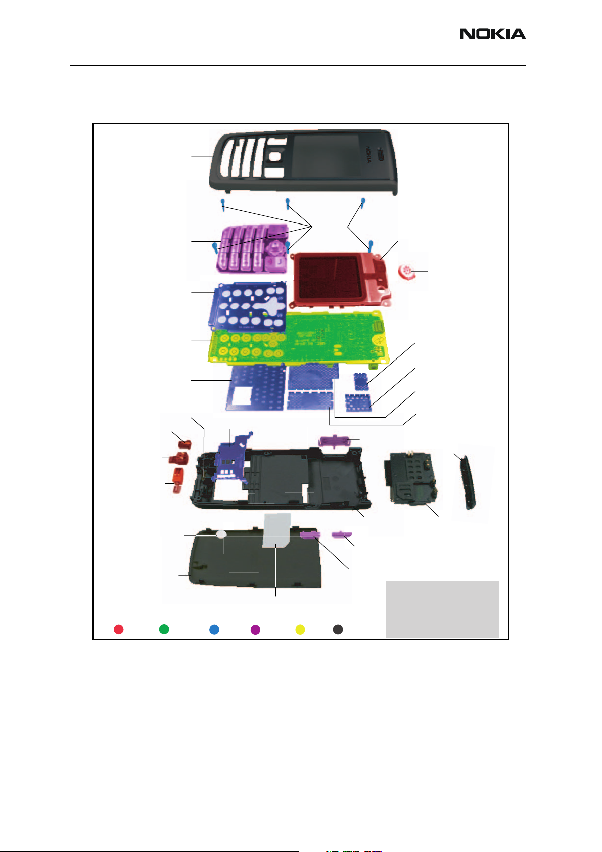
The following illustration shows an exploded view of the 2865/2865i.
A-Cover Assembly
Keymat
Domesheet Frame
Engine Module
BB Shield Lid
Bluetooth Antenna (A2)
* I019
DC Jack (A2)
I024
Microphone (A2)
I022
Vibra Motor (A2)
I023
I001
I002
I006
I007
I011
RUIM Flap (A2)-I020
Screws
M1.6x6.0
I003
LCD Module (A1)
* I004
Speaker (A1)
I005
Duplexor Shield Lid
I012
GPS Shield Lid
I008
RX Shield Lid
I009
TX Shield Lid
I010
Volume Key (A2)-I017
IR Window (A2)
I015
Antenna PIFA (A2)
I021
Water Ingress Label (A2)
I025
Battery Cover
I026
Type Label (A2)
I013
Disposal Legend:
Electro Silicone Metal Plastic PWB Cover
B-Cover (A2)-* I014
UHJ Jack Sliding Cover (A2)
I016
Push to Talk Key (A2)
I018
A1-UI Module Assembly
A2-B Cover Sub-Assembly
*-Available only as Assembly
Figure 1: 2865/2865i Exploded View
Page 4 Company Confidential ISSUE 2 - October 2006
Page 5
2865/2865i (RM-193)
Nokia Customer Care Disassembly/Assembly
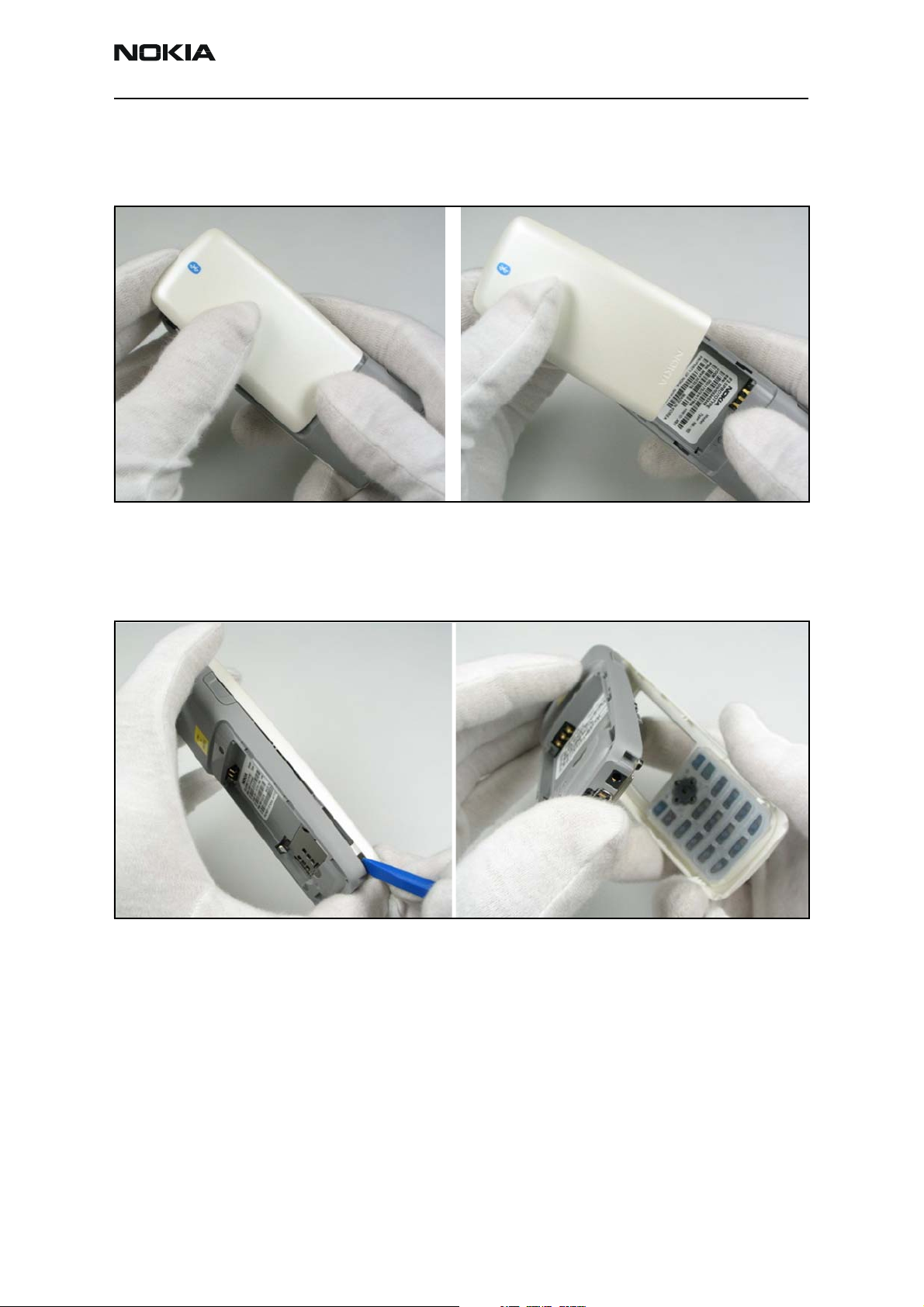
1. Remove the Battery Cover
Gently push down on the battery cover while sliding it away from the body of the mobile
terminal.
Remove the battery (if installed).
2. Separate the A- and B-Covers
Use the SS-90 wedge tool to separate the A-cover from the B-cover.
ISSUE 2 - October 2006 Company Confidential Page 5
Page 6
2865/2865i (RM-193)
Disassembly/Assembly Nokia Customer Care
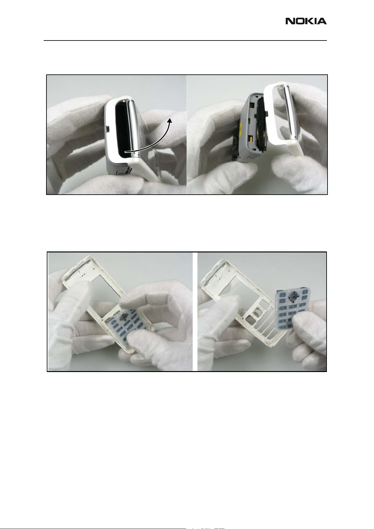
3. Remove the A-Cover
Starting from the Pop-port, rotate the A-cover up from the face of the mobile terminal.
Note: Be careful of the header cap and the retaining snaps along either side and at
the top.
4. Remove the Keypad from the A-Cover
After separating the A-cover, remove the keypad.
Page 6 Company Confidential ISSUE 2 - October 2006
Page 7
2865/2865i (RM-193)
Nokia Customer Care Disassembly/Assembly
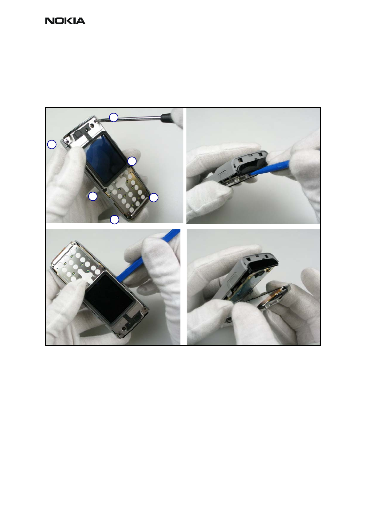
5. Remove the UI Module
Remove the six Torx retaining screws in the order below to free the UI module from the
B-cover.
Place protective plastic onto the LCD display to prevent scratches.
Use the SS-93 to gently lift and separate the UI Assembly from the B-cover.
Screw Removal Order:
1.
2.
3.
4.
6.
5.
Note: Be careful as the LCD connector is the only point physically retaining the two
modules together. Mishandling might cause serious damage
ISSUE 2 - October 2006 Company Confidential Page 7
Page 8

2865/2865i (RM-193)
Disassembly/Assembly Nokia Customer Care
6. Remove the LCD Module from the PWB
Use the SS-93 to gently pry the LCD Assembly connector from the PWB. Be careful not to
damage the LCD contacts.
Note: Be careful as the LCD connector is the only point physically retaining the two
modules together. Mishandling might cause serious damage.
Page 8 Company Confidential ISSUE 2 - October 2006
Page 9

2865/2865i (RM-193)
Nokia Customer Care Disassembly/Assembly
7. Remove the Earpiece from the LCD Assembly
Use the locating tab to gently lift and remove the speaker from its mount.
Note: Be careful not to touch the spring contacts.
8. Remove the Antenna/IHF Speaker Assembly
Gently pry the IHF Module from its position within the B-cover.
Gently grasp the module and remove it by hand. Be careful not to damage any of the
electrical contacts.
ISSUE 2 - October 2006 Company Confidential Page 9
Page 10

2865/2865i (RM-193)
Disassembly/Assembly Nokia Customer Care
9. Remove the UHJ Sliding Cover
Prior to removing the UHJ sliding cover, note the relative slot/tab arrangement and
position it so the tab lines up with the opening slot.
Use tweezers to gently pull the UHJ sliding cover away from the B-Cover.
10. Remove the Push-to-Talk Key
Use finger pressure to gently press the Push-To-Talk key inwards to free it from the
assembly.
Gently lift the Push-To-Talk key from its resting position within the B-Cover.
Page 10 Company Confidential ISSUE 2 - October 2006
Page 11

2865/2865i (RM-193)
Nokia Customer Care Disassembly/Assembly
11. Remov e the Vo l u m e K e y
Apply gentle finger pressure on the volume key towards the inside of the B-cover to
remove it.
12. Remove the DC Jack
Use the CA-44 to lift the DC Jack from within the B-cover.
Note: Be careful not to damage the spring contacts in the process.
ISSUE 2 - October 2006 Company Confidential Page 11
Page 12

2865/2865i (RM-193)
Disassembly/Assembly Nokia Customer Care
13. Remove the Microphone Module
Gently lift the microphone module from position within the B-cover.
Note: Be careful not to damage the spring contacts in the process.
14. Remove the Vibra Assembly
Carefully remove the vibra module from the B-cover.
Page 12 Company Confidential ISSUE 2 - October 2006
Page 13

2865/2865i (RM-193)
Nokia Customer Care Disassembly/Assembly
After removing, check the small metal clip in the bottom of the vibra placeholder for
damages. (This clip holds the battery cover in place). If necessary, gently remove with
tweezers and replace.
15. Remove the IR Lens
Gently grasp the B-cover and unsnap the IR Lens from the assembly.
ISSUE 2 - October 2006 Company Confidential Page 13
Page 14

2865/2865i (RM-193)
Disassembly/Assembly Nokia Customer Care
Note: The B-cover holds the IR lens at both ends and by three small locating pins.
Ensure that neither the B-cover nor the IR lens is damaged in the removal
process.
16. Remove the SIM Cover
Hold the B-cover so that you can open the SIM cover.
Page 14 Company Confidential ISSUE 2 - October 2006
Page 15

2865/2865i (RM-193)
Nokia Customer Care Disassembly/Assembly
Assembly Instructions
Use the following procedure to assemble the mobile terminal.
1. Install the SIM Cover
Insert one end of the SIM cover into the B-cover, then lock the other end into place.
1.
2.
Flip down and close the SIM cover.
2. Install the IR Lens
Align the five pins and holes on the IR lens and B-cover. Gently snap the IR lens into the
assembly.
ISSUE 2 - October 2006 Company Confidential Page 15
Page 16

2865/2865i (RM-193)
Disassembly/Assembly Nokia Customer Care
Note: The B-cover holds the IR lens at both ends and by three small locating pins.
Ensure that neither the B-cover nor the IR lens is damaged in the installation
process.
Page 16 Company Confidential ISSUE 2 - October 2006
Page 17

2865/2865i (RM-193)
Nokia Customer Care Disassembly/Assembly
3. Install the Battery Cover Clip and Vibra Assembly
If the battery cover clip has been removed, replace it. If not, skip to installing the vibra
assembly.
Check
for
clip.
Insert
clip if
missing
If you need to install the battery cover clip, gently grasp the clip with tweezers and insert
into the slot.
ISSUE 2 - October 2006 Company Confidential Page 17
Page 18

2865/2865i (RM-193)
Disassembly/Assembly Nokia Customer Care
4. Install the Vibra Assembly
Using tweezers, carefully insert the vibra module into the B-cover. If required, gently
push down to seat the assembly into place.
5. Install the Microphone Module
Using tweezers, carefully insert the microphone module into the B-cover.
Note: Be careful not to damage the spring contacts in the process.
Page 18 Company Confidential ISSUE 2 - October 2006
Page 19

2865/2865i (RM-193)
Nokia Customer Care Disassembly/Assembly
6. Install the DC Jack
Insert the CA-44 into the DC jack, and snap it into the B-cover.
Note: Be careful not to damage the spring contacts in the process.
If required, carefully gently press down on the DC jack to ensure it is properly seated.
7. Install the Volume Key
Align the two end fins and center pin of the volume key to match up with the slot in the
B-cover.
ISSUE 2 - October 2006 Company Confidential Page 19
Page 20

2865/2865i (RM-193)
Disassembly/Assembly Nokia Customer Care
After alignment, slip the volume key into place.
If required, gently push the key towards the outside of the mobile terminal to properly
seat the key into the B-cover.
8. Install the Push-to-Talk Key
Angle the Push-To-Talk key slightly and insert into the slot on the B-cover assembly.
Align the bottom and two side fins into the slots on the B-cover. Press down into place.
Page 20 Company Confidential ISSUE 2 - October 2006
Page 21

2865/2865i (RM-193)
Nokia Customer Care Disassembly/Assembly
9. Install the UHJ Sliding Cover
Prior to inserting the UHJ sliding cover, align the tab with the opening slot.
After aligning, insert and slide up or down to prevent key from separating from cover.
ISSUE 2 - October 2006 Company Confidential Page 21
Page 22

2865/2865i (RM-193)
Disassembly/Assembly Nokia Customer Care
10. Install the Antenna/IHF Speaker Assembly
Locate the pin on the B-cover.
Align and seat pin
Place the antenna/IHF speaker assembly over the B-cover and align the pin with the hole
in the antenna/IHF assembly. (1.) Gently lower the top of the antenna/IHF assembly and
gently seat the assembly onto the pin. (2.) Once seated, carefully press down and seat
the Antenna/IHF assembly into the B-cover.
11. Install the Earpiece from LCD Assembly
Using tweezers, align the small tab and gently insert the Speaker onto the mount/slot on
the LCD display. Carefully press the unit into place to ensure proper seating.
1.
Seat pin/top of Ant./IHF
Seat bottom of
2.
Ant./IHF
Note: Be careful not to touch the spring contacts.
Page 22 Company Confidential ISSUE 2 - October 2006
Page 23

2865/2865i (RM-193)
Nokia Customer Care Disassembly/Assembly
ISSUE 2 - October 2006 Company Confidential Page 23
Page 24

2865/2865i (RM-193)
Disassembly/Assembly Nokia Customer Care
12. Install the LCD module on the PWB
Align the connector pads of the LCD assembly connector and PWB.
PWB Connector Pad
LCD Connector Pad
Note: Be careful as the LCD connector is the only point physically retaining the two
modules together. Mishandling might cause serious damage.
After aligning, close the two assemblies together and gently press the connectors until
properly seated. You will feel the connectors lightly snap together.
This LCD-PWB assembly is now referred to as the UI module.
13. Install the UI Module
Insert the plastic alignment pin on the upper left corner of the B-cover into the
matching hole on the upper left corner of the PWB assembly.
Note: The LCD connector is the only point physically retaining the LCD and PWB
modules together. Mishandling might cause serious damage.
Page 24 Company Confidential ISSUE 2 - October 2006
Page 25

2865/2865i (RM-193)
Nokia Customer Care Disassembly/Assembly
Note: Place protective plastic onto LCD display to prevent scratches.
Align
Pin and
Hole
After the pin is aligned and inserted into the hole, ensure all of the buttons align and
insert the left side of the PWB. Lower the right side into place on the B-cover, and check
that the Push-to-Talk key and UHJ jack are properly aligned. Ensure the battery
connector on the PWB is properly aligned so the connectors show through the opening
on the back of B-cover.
Battery Connector
ISSUE 2 - October 2006 Company Confidential Page 25
Page 26

2865/2865i (RM-193)
Disassembly/Assembly Nokia Customer Care
In the order listed, insert the 6-Torx retaining screws to secure the UI module to the
B-cover. Use 18Ncm +/- 2Ncm torque for all six screws.
Screw Install Order:
1.
2.
3.
4.
14. Install the Keypad from A-Cover
Insert the keypad into the A-cover. Ensure the keypad is properly seated.
5.
6.
Page 26 Company Confidential ISSUE 2 - October 2006
Page 27

2865/2865i (RM-193)
Nokia Customer Care Disassembly/Assembly
15. Combining the A- and B-Covers
Angle the A-cover so the tops of both covers come together and the bottoms are open.
Insert the two tabs on the top of the A-cover into the two slots on the top of the
B-cover.
After inserting the tabs into the slots, pivot and close the A-cover to the B-cover.
After closing, press the two covers together all around the edge of both covers to ensure
all snaps have seated.
ISSUE 2 - October 2006 Company Confidential Page 27
Page 28

2865/2865i (RM-193)
Disassembly/Assembly Nokia Customer Care
16. Install the Battery Cover
If you want to test the mobile terminal on a test jig, skip this step and go directly to
testing the mobile terminal on the test gig. However, if you are finished with all testing
and are ready to finish the mobile terminal assembly, continue with this step.
If required, insert the battery into the mobile terminal.
Place the battery cover over the back of the B-cover/mobile terminal assembly and align
the six tabs on the battery cover to the six slots on the B-cover.
After inserting the tabs into the slots, slide the battery cover toward the top of the
mobile terminal until the battery cover is seated tight against the B-cover.
Page 28 Company Confidential ISSUE 2 - October 2006
 Loading...