

Page 1

Nokia Customer Care
2865/2865i (RM-193)
Mobile Terminals
Antenna Description and
Troubleshooting
ISSUE 2 - October 2006 Company Confidential ©2006 Nokia Corporation
Page 2

2865/2865i (RM-193)
Antenna Description and Troubleshooting Nokia Customer Care
Contents Page
Introduction ..................................................................................................................................................... 3
Visual Quality Requirements ....................................................................................................................... 3
Failures and Corrective Measures.............................................................................................................. 3
Antenna Position ......................................................................................................................................... 3
Internal Antenna ..........................................................................................................................................4
Damaged RF Feed, Ground Pins, or IHF Speaker Pins ........................................................................4
Damaged GPS Antenna, Pins, or Heat Stake .......................................................................................5
Bluetooth Antenna ......................................................................................................................................6
Obstructed IHF Speaker, RF Feed, and Ground Pads .........................................................................6
Obstructed Bluetooth Antenna Pads .....................................................................................................7
Missing Main Antenna Matching Circuit ............................................................................................. 7
Missing BT Antenna Matching Circuit ..................................................................................................8
CDMA Or GPS RF Connector Failure ......................................................................................................9
Grounding the Display Shield and Frame .............................................................................................9
Page 2 Company Confidential ISSUE 2 - October 2006
Page 3
2865/2865i (RM-193)
Nokia Customer Care Antenna Description and Troubleshooting
Introduction
The mobile terminal incorporates an internal antenna. This antenna arrangement is used
for AMPS/CELL and PCS frequency bands. The internal antenna assembly consists of a
Planar Inverted-F Antenna (PIFA) used for the cellular engine and an Inverted-F antenna
(IFA) used for the GPS engine, which is placed on the side of internal antenna body.
Visual Quality Requirements
Following are the minimum acceptable visual quality requirements of the internal
antenna assembly:
• Use gloves when handling antennas. Do not touch the antenna radiator with bare
hands.
• No visual cracks or mechanical defects.
• No oil, dirt, or particles are present on the parts.
• Align the radiator with the plastic housing.
• GPS antenna contacts must be inside the plastic housing.
• Radiator must be flat with no warping.
• All pins must be at the same level.
Failures and Corrective Measures
Antenna Position
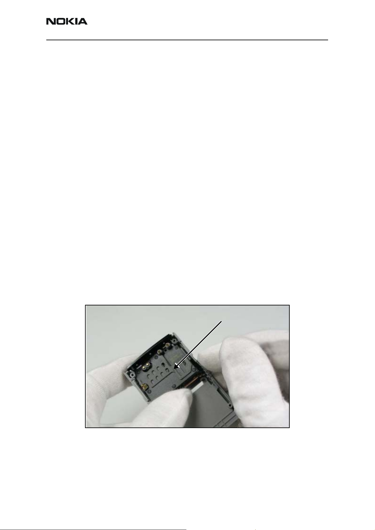
The internal antenna is assembled into the B-cover as shown in Figure 1. If no internal
antenna is installed, the antenna gain will be degraded by more than 25 dB.
Antenna Module
Figure 1: B-cover assembly with Antenna module
If the internal antenna is missing, install one. If the radiator looks obviously damaged,
then replace the internal antenna.
ISSUE 2 - October 2006 Company Confidential Page 3
Page 4

2865/2865i (RM-193)
Antenna Description and Troubleshooting Nokia Customer Care
Internal Antenna
The internal antenna has a metal sheet (main antenna radiator) and a metal strip (GPS
antenna) attached to a plastic carrier.
Main Antenna
Radiator
GPS Antenna
Radiator
Figure 2: Internal antenna
Note: The GPS antenna is only functional on models that support the GPS engine.
Damaged RF Feed, Ground Pins, or IHF Speaker Pins
The main antenna and the GPS antenna have pins (spring clips) that must properly touch
the PWB. Positioning of these pogo pins is shown in Figure 3. Two pogo pins are inserted
in the black plastic module.
Ground Pogo Pin
Main Antenna
IHF Mini Speaker
Pogo Pins
RF Feed Pin
GPS Antenna
Ground Pin
GPS Antenna
RF Feed Pogo Pin
Main Antenna
Rubber Pad
Figure 3: Internal Antenna
• The main antenna is connected to the PWB with two pogo pins. The two pogo
pins are inserted in the black plastic module. One end of the pogo pin touches
the antenna; the other end touches the pad on the PWB. If either of the pins is
missing, or either of them is obviously damaged (i.e., get stuck in the black plastic
module or loses the inside spring force), the antenna loses contact to the PWB. If
this happens, replace the antenna module with a good one.
Page 4 Company Confidential ISSUE 2 - October 2006
Page 5

2865/2865i (RM-193)
Nokia Customer Care Antenna Description and Troubleshooting
• If the RF feed pin does not touch the PWB, the antenna gain degrades by more
than 25 dB. If the ground pin does not touch the PWB, the antenna gain may
degrade about 5 to 10 dB. If either of the IHF speaker pins is damaged or missing,
the speaker does not connect to the PWB. If this happens, replace the antenna
module with the correct one. If the rubber pad on the antenna module is missing,
replace the antenna module with a functional antenna module.
• If the ground pin of the main antenna does not touch the PWB, the antenna gain
degrades about 5 to 10 dB and the GPS antenna is detuned.
• If the GPS antenna’s RF feed pin does not touch the PWB, then the GPS antenna
gain degrades by more than 20 dB.
• If the ground pin of the GPS antenna does not touch the PWB, the GPS antenna
gain may degrade by more than 5 dB.
• If either the RF feed pin or ground pin are broken or bent such that either pin
does not touch the PWB, replace the internal antenna.
• If either the RF pin or ground pin springs appear damaged, replace the internal
antenna.
• If either of the IHF speaker pins is damaged or missing, the speaker does not
connect to the PWB. Replace the antenna module with the correct one.
• If the rubber pad on the antenna module is missing, replace the antenna module
with a properly assembled antenna module.
Damaged GPS Antenna, Pins, or Heat Stake
The GPS antenna is heat-staked to the plastic.
Heat Stake
Ground Pin of
GPS Antenna
RF Feed Pin of
GPS Antenna
Heat Stake
GPS Antenna
Figure 4: Back view (GPS antenna)
If any of the following problems occur, replace the antenna with a correct one:
• GPS antenna looks obviously damaged
• Any of the 5 heat stakes look damaged and the GPS antenna is loose
ISSUE 2 - October 2006 Company Confidential Page 5
Page 6

2865/2865i (RM-193)
Antenna Description and Troubleshooting Nokia Customer Care
• Any of the 5 heat stakes are overheat and melt the GPS antenna into the plastic,
leaving the antenna distorted and bent
• Either the GPS antenna feed or the ground leg is broken or bent such that either
pin does not touch the PWB
Bluetooth Antenna
Bluetooth
Antenna
Heat Stake
The Bluetooth (BT) antenna is a metal stamp part which is heat staked to the B-cover
assembly. If any of the following happens, replace the BT antenna:
• BT antenna is missing
• BT antenna looks damaged
• Any of the heat stakes look damaged and the BT antenna is loose
• Any of the heat stakes overheat and melt BT antenna into B-cover, which causes
the antenna to look distorted and bent
• BT antenna feed leg is broken or bent such that it does not touch the PWB
Obstructed IHF Speaker, RF Feed, and Ground Pads
The antenna module connects to the PWB at specific places as shown in Figure 5.
RF Feed Pad for
GPS Antenna
IHF Speaker Pads
Ground Pad for
GPS Antenna
GPS RF Connector
Ground Pad for
Main Antenna
RF Feed Pad for
Main Antenna
Figure 5: PWB layout of IHF speaker, RF feed, and ground pads
Page 6 Company Confidential ISSUE 2 - October 2006
Page 7

2865/2865i (RM-193)
Nokia Customer Care Antenna Description and Troubleshooting
Check for the following problems:
• If the main antenna feed pad is obstructed, removed or covered, the internal
antenna feed pogo pin may not touch the PWB and the antenna gain degrades by
more than 25 dB.
• If the main antenna ground pad is obstructed, removed or covered, the ground
pogo pin may not be touch the PWB and the antenna gain degrades by more
than 5 dB.
• If corrosion is present or the pads are missing, replace the PWB.
• If either pad is obstructed or covered, clear or clean the pads.
• If the GPS antenna feed pad is obstructed, removed or covered, the GPS antenna
feed leg does not touch the PWB.
• If the ground pad is obstructed, removed or covered, the ground spring clip does
not touch the PWB.
• If the IHF (Internal Hands Free) speaker pads are obstructed, removed or covered,
the IHF speaker does not produce sound.
• If corrosion is present or the pads are missing, replace the PWB.
• If either IHF speaker pad is obstructed or covered, clear and clean the pad.
Obstructed Bluetooth Antenna Pads
Figure 6: BT Antenna Feed Pad
Missing Main Antenna Matching Circuit
BT Antenna
Feed Pad
If the BT antenna feed pad is obstructed, removed or covered, the BT antenna feed leg
does not touch the PWB. If corrosion is present or the pads are missing, replace the PWB.
ISSUE 2 - October 2006 Company Confidential Page 7
Page 8

2865/2865i (RM-193)
Antenna Description and Troubleshooting Nokia Customer Care
If the feed pad is obstructed or covered, clear or clean the pads.
Main Antenna
Matching Circuit
Figure 7: Main antenna matching circuit
The main antenna matching circuit is located next to the main antenna feed pad. The
main antenna matching circuit consists of a series inductor of 1.5 nH and shunt cap of
1.2 nH. If the main antenna matching circuit is not properly installed or if any of the two
components are missing, the antenna gain degrades by about 15 dB.
Missing BT Antenna Matching Circuit
The BT antenna matching circuit is located next to the BT antenna feed pad. The BT
antenna matching circuit consists of a series cap of 3.3 pF and shunt cap of 1.8 pF. If the
BT antenna matching circuit is not properly installed or if any of the two components are
missing, the antenna gain degrades by about 15 dB.
BT Antenna
Matching Circuit
Figure 8: BT antenna matching circuit
Page 8 Company Confidential ISSUE 2 - October 2006
Page 9

2865/2865i (RM-193)
Nokia Customer Care Antenna Description and Troubleshooting
CDMA Or GPS RF Connector Failure
CDMA and GPS use the same type of RF connector. The RF connector fails when it does
not connect the RF input to the RF output.
• If this happens to the CDMA RF connector, the antenna gain degrades by about
25 dB.
• If this happens to GPS RF connector, the GPS antenna gain degrades by about
20 dB.
Check the RF connector by testing for DC conductivity between the RF input and RF
output. Perform the DC conductivity test without any cable attached to the RF
connector. Because the RF connector is also a switch, the RF output is disconnected from
the RF input when a cable is inserted into the RF connector. When a cable is not inserted,
the RF input is connected to the RF output of RF connector. The locations of the both RF
connectors are shown in Figure 5 on page 6.
• CDMA RF input - connects to duplexer
• CDMA RF output - connects to antenna pad through vias
• GPS RF input - connects to GPS ceramic filter output
• GPS RF output - connects to GPS antenna matching circuits
• RF connector - connects to coaxial cable
If the RF input is not connected properly to the RF output, replace the RF connector.
Grounding the Display Shield and Frame
The display frame is grounded to the PWB through two ground clips with screws. The
grounding of the display frame and shield impacts the radiation performance of the
phone.
Display frame grounding
through screws
Display frame
grounding tabs
Figure 9: Display assembly ground points
ISSUE 2 - October 2006 Company Confidential Page 9
Page 10

2865/2865i (RM-193)
Antenna Description and Troubleshooting Nokia Customer Care
Check for the following problems:
• If the clips are not touching the PWB, or are corroded, obstructed, replace the
display frame.
• If the screws are loose, tighten them.
• If the screws are missing, install new ones. Figure 9 shows the contact between
the display frame ground clips and the PWB in greater detail.
• If the metal display frame is damaged or it is not properly attached to the rest of
the display assembly, replace the entire display assembly.
Page 10 Company Confidential ISSUE 2 - October 2006
 Loading...