

Page 1
CMO Operations & Logistics
Training and Vendor Development
Multimedia Creation & Support
SERVICE MANUAL
Page (45)
CONFIDENTIAL
1
Level 1&2
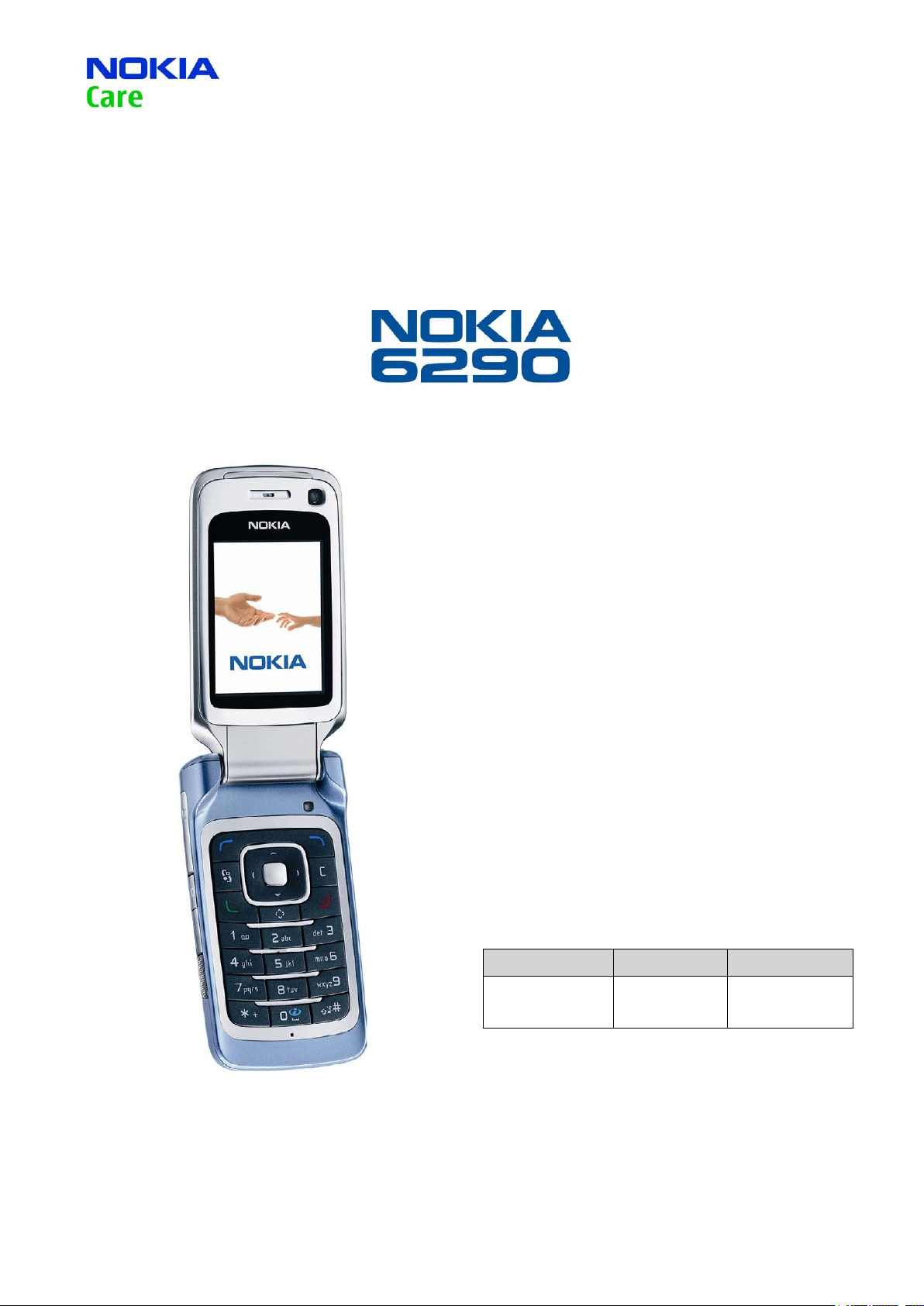
RM-176
Transceiver characteristics:
Approved 2.0
MGR
13.Apr.2007
Dual Mode:
-GSM Band: Tri-band phone for EGSM 850/900/1800/1900MHz
-WCDMA Band: 2100
Camera:
-Main: 2,0 Megapixel camera with integrated ash
-2nd: CIF camera for video call
Display: Active TFT color display with 16M colors,
resolution 320 x 240 pixel; active area 33.48x44.64mm
Operating System: Series 60
Bluetooth
IRDA
FM radio
Connector: Mini USB Connector, AV Connector
Transceiver with BL-5F Li-Ion battery pack
Talk time Standby Note
up to 3h up to 11days
Depends on network
parameters
Environmental characteristics:
• Lead-free soldered
Service Manual 6290 RM-176 Copyright © 2007 NOKIA Corporation. All rights reserved.
Page 2
Page (45)
CMO Operations & Logistics
Training and Vendor Development
Multimedia Creation & Support CONFIDENTIAL
2
Approved 2.0
MGR
13.Apr.2007
TABLE OF CONTENTS
1.
2.
3.
4.
5.
6.
7.
8.
9.
10.
11.
12.
13.
14.
15.
16.
17.
18.
19.
20.
21.
22.
23.
24.
25.
26.
27.
28.
INTRODUCTION 3
GENERAL REPAIR INFORMATION
EXPLODED VIEW
SPARE PARTS OVERVIEW
GENERAL RECYCLING RECOMMENDATION
LEVEL 2 SOLDER COMPONENTS
SERVICE TOOLS
SW-UPDATE 1
UPPER BLOCK DISASSEMBLY 1
UPPER BLOCK ASSEMBLY 1
LOWER BLOCK DISASSEMBLY 2
LOWER BLOCK DISASSEMBLY 2
LEGEND FOR QUICK TROUBLE SHOOTER 3
QUICK TROUBLE SHOOTER - POWER ON 3
QUICK TROUBLE SHOOTER - CHARGING 3
QUICK TROUBLE SHOOTER - NO SERVICE 3
QUICK TROUBLE SHOOTER - BLUETOOTH 3
QUICK TROUBLE SHOOTER - EARPIECE 3
QUICK TROUBLE SHOOTER - IHF SPEAKER 3
QUICK TROUBLE SHOOTER - DISPLAY 3
QUICK TROUBLE SHOOTER - MICROPHONE 3
QUICK TROUBLE SHOOTER - KEYMAT 3
QUICK TROUBLE SHOOTER - UI KEYMAT 4
QUICK TROUBLE SHOOTER - PUSH TO TALK 4
QUICK TROUBLE SHOOTER - VOLUME KEYS 4
QUICK TROUBLE SHOOTER - CARD READER 4
QUICK TROUBLE SHOOTER - CAMERA 4
QUICK TROUBLE SHOOTER - CAMERA CIF 4
Page
4
5
6
7
8
9
1
2
7
1
6
0
1
2
3
4
5
6
7
8
9
0
1
2
3
4
5
CHANGE HISTORY
Status Version No. Date Comments
Draft 0.1 29.Jan.2007 Initial draft
Approved 1.0 26.Feb.2007 Approval
Approved 2.0 13.Apr.2007 Exploded view/Spare Parts overview updated
Service Manual 6290 RM-176 Copyright © 2007 NOKIA Corporation. All rights reserved.
Page 3
Page (45)
CMO Operations & Logistics
Training and Vendor Development
Multimedia Creation & Support CONFIDENTIAL
3
Approved 2.0
MGR
13.Apr.2007
INTRODUCTION1.
The purpose of this document is to help NOKIA service levels 1 and 2 workshop technicians to carry out service to
NOKIA products. This Service Manual is to be used only by authorized NOKIA service suppliers, and the content of it is
confidential. Please note that NOKIA provides also other guidance documents (e.g. Service Bulletins) for service suppliers, follow these regularly and comply with the given instructions.
While every endeavor has been made to ensure the accuracy of this document, some errors may exist.
If you find any errors or if you have further suggestions, please notify NOKIA using the address below:
mailto:cc-ts-rc.documentation@nokia.com
Please keep in mind also that this documentation is continuously being updated and modified, so watch always out
for the newest version.
Warnings and Cautions
Please refer to the phone’s user guide for instructions relating to operation, care and maintenance including important safety information. Note also the following:
Warnings:
CARE MUST BE TAKEN ON INSTALLATION IN VEHICLES FITTED WITH ELECTRONIC ENGINE MANAGEMENT SYSTEMS
1.
AND ANTI–SKID BRAKING SYSTEMS. UNDER CERTAIN FAULT CONDITIONS, EMITTED RF ENERGY CAN AFFECT THEIR
OPERATION. IF NECESSARY, CONSULT THE VEHICLE DEALER/MANUFACTURER TO DETERMINE THE IMMUNITY OF VEHICLE ELECTRONIC SYSTEMS TO RF ENERGY.
THE HANDPORTABLE TELEPHONE MUST NOT BE OPERATED IN AREAS LIKELY TO CONTAIN POTENTIALLY EXPLOSIVE
2.
ATMOSPHERES, EG PETROL STATIONS (SERVICE STATIONS), BLASTING AREAS ETC.
OPERATION OF ANY RADIO TRANSMITTING EQUIPMENT, INCLUDING CELLULAR TELEPHONES, MAY INTERFERE WITH
3.
THE FUNCTIONALITY OF INADEQUATELY PROTECTED MEDICAL DEVICES. CONSULT A PHYSICIAN OR THE MANUFACTURER OF THE MEDICAL DEVICE IF YOU HAVE ANY QUESTIONS. OTHER ELECTRONIC EQUIPMENT MAY ALSO BE SUBJECT TO
INTERFERENCE.
Cautions:
1. Servicing and alignment must be undertaken by qualified personnel only.
2. Ensure all work is carried out at an anti–static workstation and that an anti–static wrist strap is worn.
3. Use only approved components as specified in the parts list.
4. Ensure all components, modules screws and insulators are correctly re–fitted after servicing and alignment.
5. Ensure all cables and wires are repositioned correctly.
Electrostatic discharge can easily damage the sensitive components of electronic products.
Therefore every Service Supplier has to take care of all precautions, which are mentioned in the
service level related “Service Partner Requirements”, available on NOKIA Online. Also see ESD
Protection Requirements in this Service Manual.
Service Manual 6290 RM-176 Copyright © 2007 NOKIA Corporation. All rights reserved.
Page 4

(45)
Page
CMO Operations & Logistics
Training and Vendor Development
Multimedia Creation & Support CONFIDENTIAL
4
Approved 2.0
13.Apr.2007
GENERAL REPAIR INFORMATION2.
In this section the technician will get some general hints how to carry out repairs:
To familiarize oneself with NOKIA product read the tutorials or user guide on www.nokia.com -->Support-->
•
Phones, by selecting the Phone Model.
Before starting the repair you must take care of ESD precautions like being in your ESD Protected Area and con-
•
necting your wristband.
Use gloves to avoid corrosion and fingerprints.
•
Protect windows and displays with a film to avoid dust and scratches.
•
When cleaning the LCD Module any lint-free cloth can be used (e.g. Micro-Fibre cloth).
•
When cleaning the pads you have to use a soft cloth/ESD brush and Isopropanol. It is not allowed to use a glass
•
fiber pencil because it scratches the surface and will lead later on to corrosion.
Mechanical parts (except shielding lids and bent parts), which didn’t repair the failure, can be reused, if they are
•
not soldered.
When removing the shielding lids make sure to replace them with new ones, otherwise the high-frequency
•
leakage can have an influence on the device.
Always use original NOKIA spare parts.
•
Check the soldering joints of the parts, which are concerned regarding the indicated error (e.g. soldered connec-
•
tors or switches) and resolder them if necessary (Level 2 only).
Remove redundant soldering flux after repair.
•
Meet the torque requirements when assembling the unit (see also the document “torques for transceiver as-
•
sembly” on NOKIA Partner Web Site/NOKIA Online).
Always use your own equipment for testing where you are sure that it works. E.g. if the customer complains
•
about charger function, please test the phone with your own charger to be sure if phone or charger causes the
malfunction.
A SIM card is needed for all GoNoGo tests.
•
When doing the fault log entries, always note the Item code, which caused the malfunction. Also, fill in the ap-
•
propriate part code from the assembly, if needed.
Please be aware that some malfunctions could be software related and solved by an update.
•
MGR
There are several documents available on NOL, which have to be followed:
•
•
First, take care for the latest content pages of Service Bulletins, which are always available for each folder on
•
NOKIA Online. This is also important to recognize, if existing documents have become invalid.
•
The service level indicator at the bottom of each document tells the appropriate destination.
•
Downloads > Support Library >
1. Instructions
2. General Service Bulletins
3. Product related documents
4. Spare Part Service Bulletins
5. Service Tools Service Bulletins
6. Common Software Service Bulletins
etc,…
Use General SB-217 as a reference or overview.
Please also check NOKIA Online (NOL) for latest news and files on a regular basis.
Service Manual 6290 RM-176 Copyright © 2007 NOKIA Corporation. All rights reserved.
Page 5
Page (45)
CMO Operations & Logistics
Training and Vendor Development
Multimedia Creation & Support CONFIDENTIAL
5
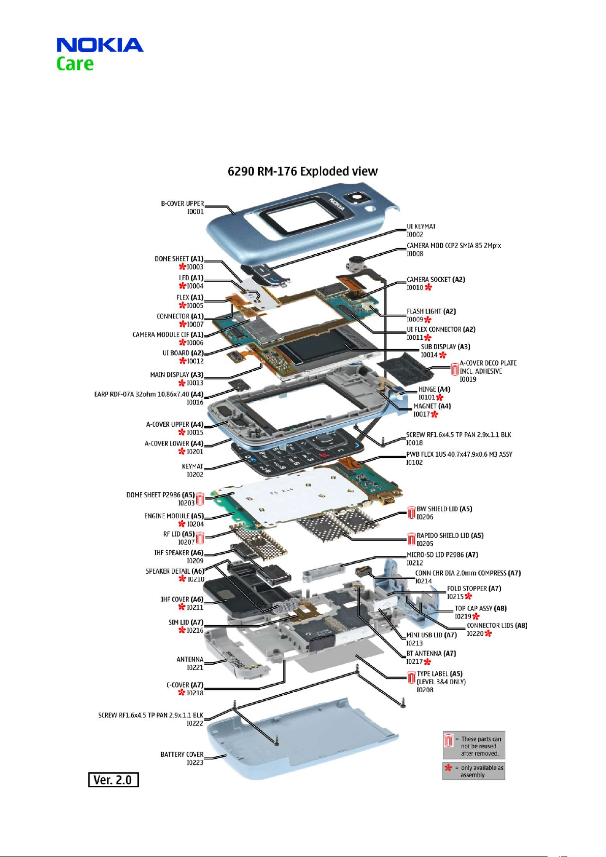
EXPLODED VIEW3.
See corresponding ITEM/CIRCUIT REF in the Spare Parts Service Bulletins on NOL.
Approved 2.0
MGR
13.Apr.2007
Service Manual 6290 RM-176 Copyright © 2007 NOKIA Corporation. All rights reserved.
Page 6
Page (45)
CMO Operations & Logistics
Training and Vendor Development
Multimedia Creation & Support CONFIDENTIAL
6
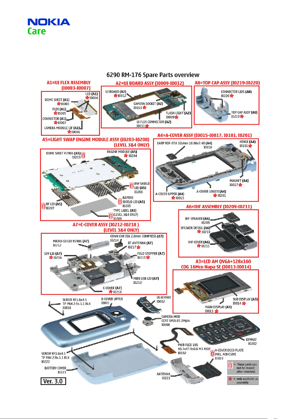
SPARE PARTS OVERVIEW4.
Approved 2.0
MGR
13.Apr.2007
Service Manual 6290 RM-176 Copyright © 2007 NOKIA Corporation. All rights reserved.
Page 7
Page (45)
CMO Operations & Logistics
Training and Vendor Development
Multimedia Creation & Support CONFIDENTIAL
7
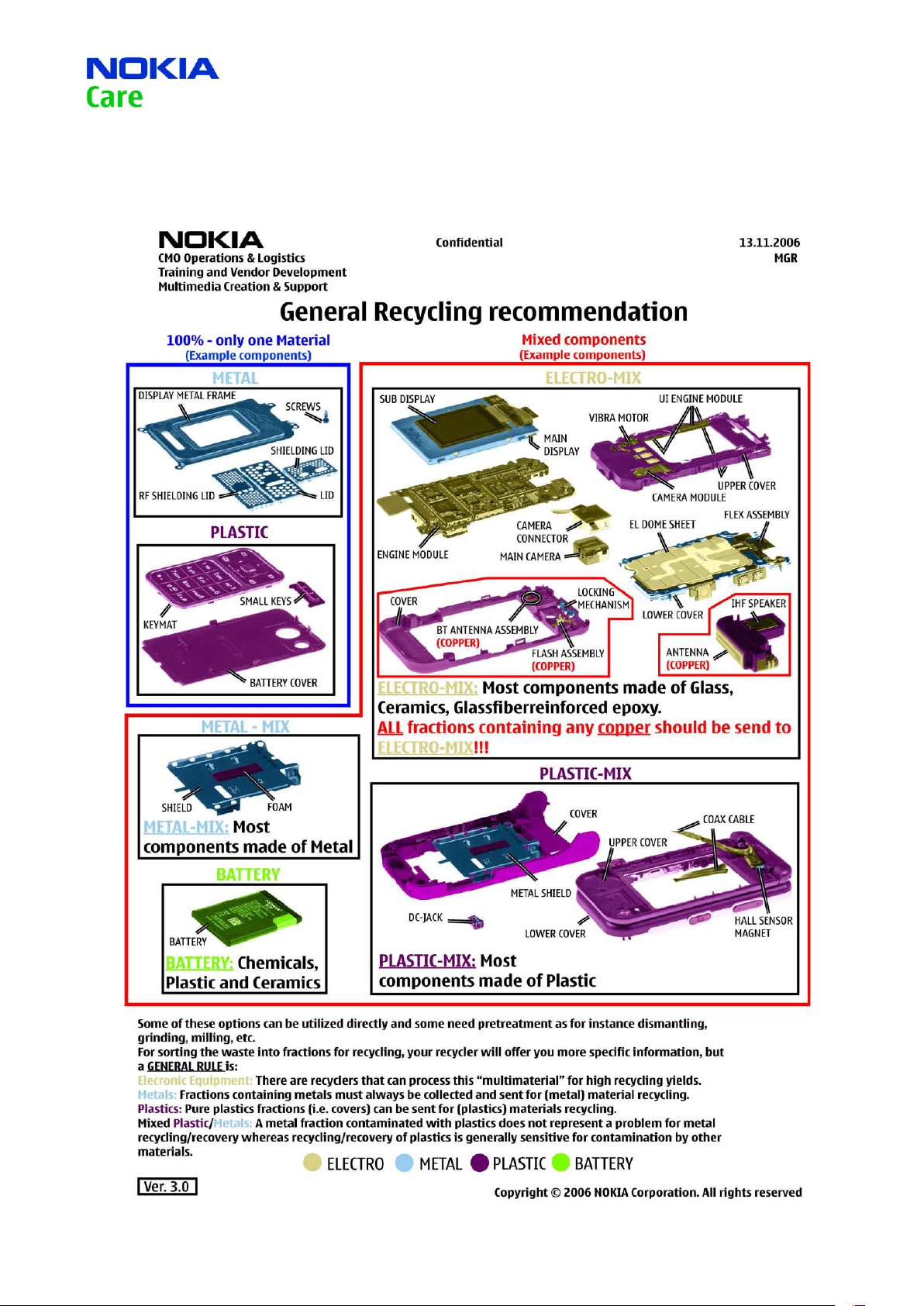
GENERAL RECYCLING RECOMMENDATION5.
Approved 2.0
MGR
13.Apr.2007
Service Manual 6290 RM-176 Copyright © 2007 NOKIA Corporation. All rights reserved.
Page 8
Page (45)
CMO Operations & Logistics
Training and Vendor Development
Multimedia Creation & Support CONFIDENTIAL
8
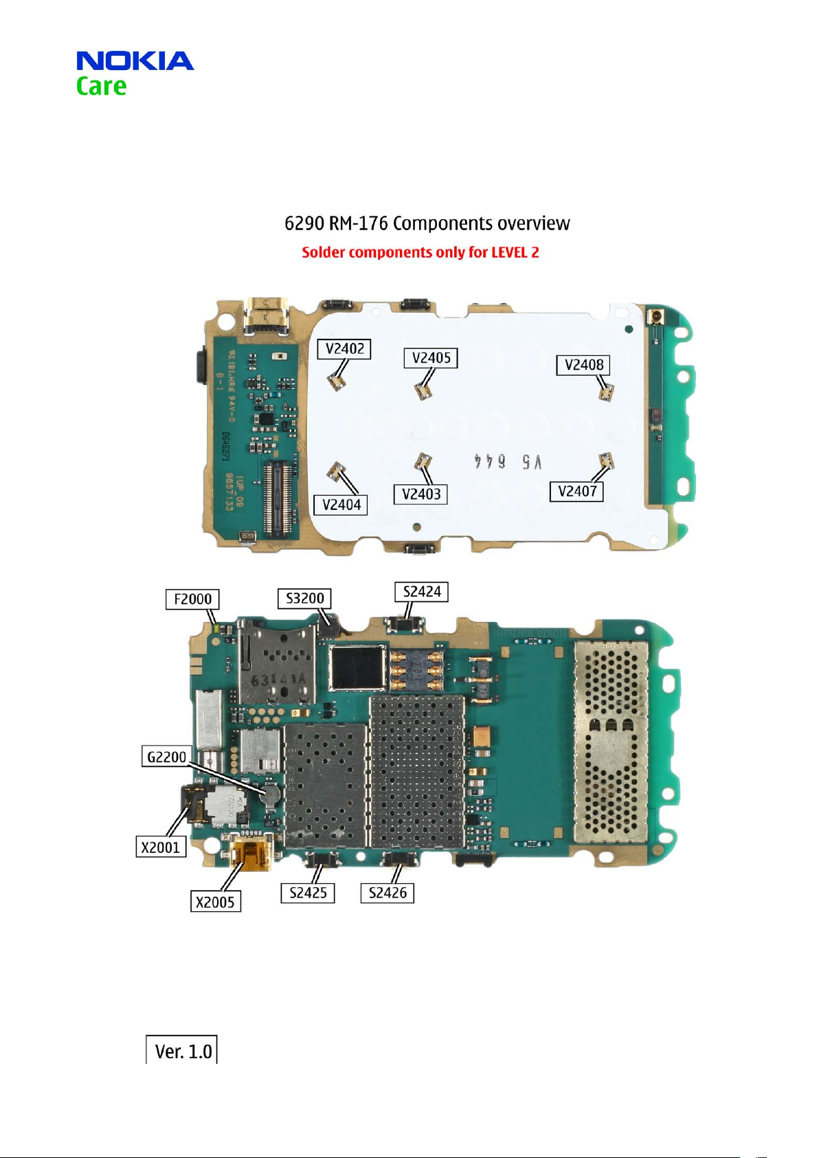
LEVEL 2 SOLDER COMPONENTS6.
Approved 2.0
MGR
13.Apr.2007
Service Manual 6290 RM-176 Copyright © 2007 NOKIA Corporation. All rights reserved.
Page 9
Page
CMO Operations & Logistics
Training and Vendor Development
Multimedia Creation & Support CONFIDENTIAL
9
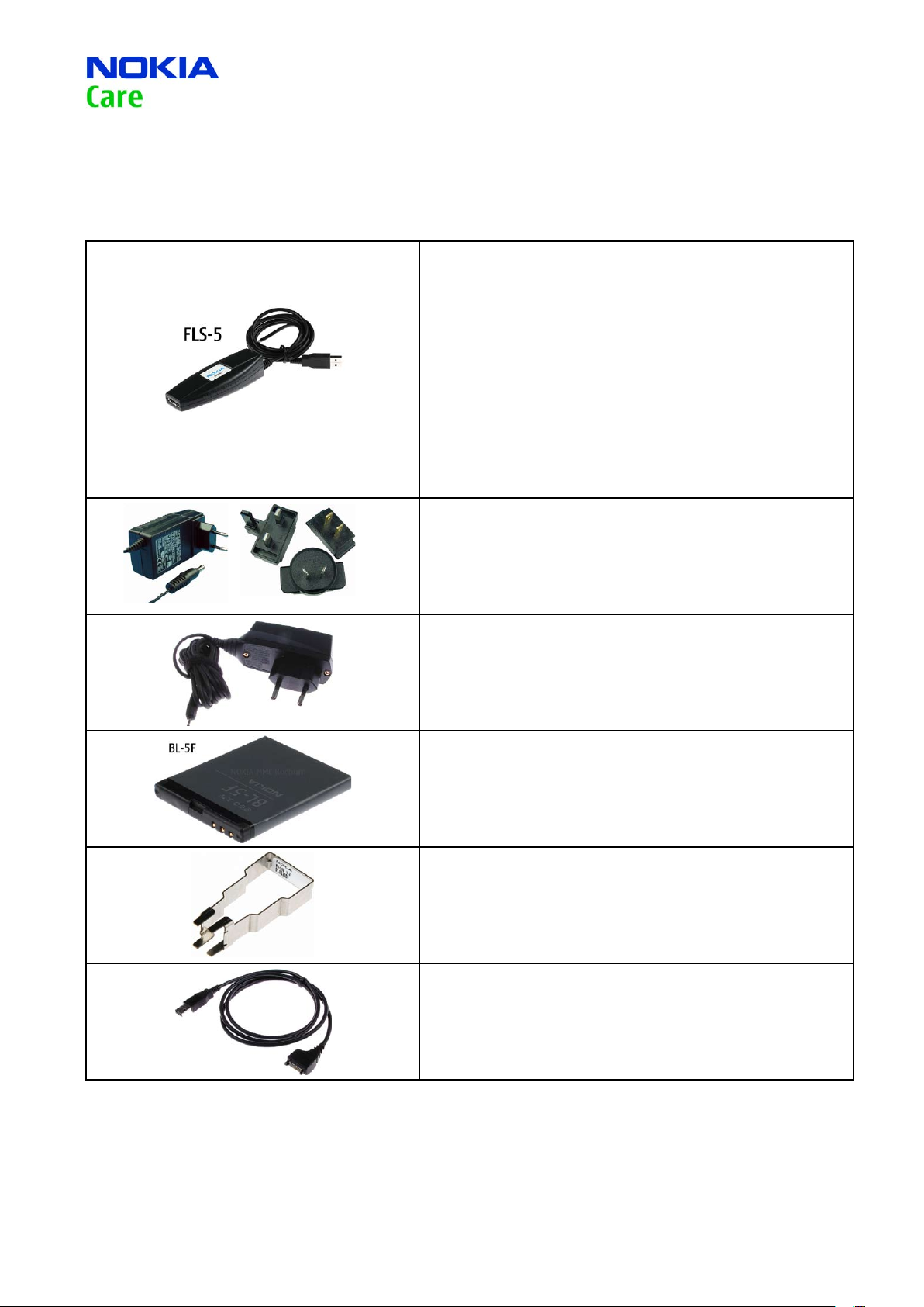
SERVICE TOOLS7.
FLS-5 incl. ACF-8, Driver and User Guide
Dongle and flash device incorporated into one package, developed specifically for POS use.
(45)
Approved 2.0
MGR
13.Apr.2007
ACF-8
Universal Power Supply is used to power FLS-4S.
Travel Charger AC-4
Small and lightweight charger for fast charging of your phone
battery.
Internal Battery BL-5F
Inserted under the back cover, this Li-Ion battery provides
power in a lightweight package.
SS-102
Camera removal tool.
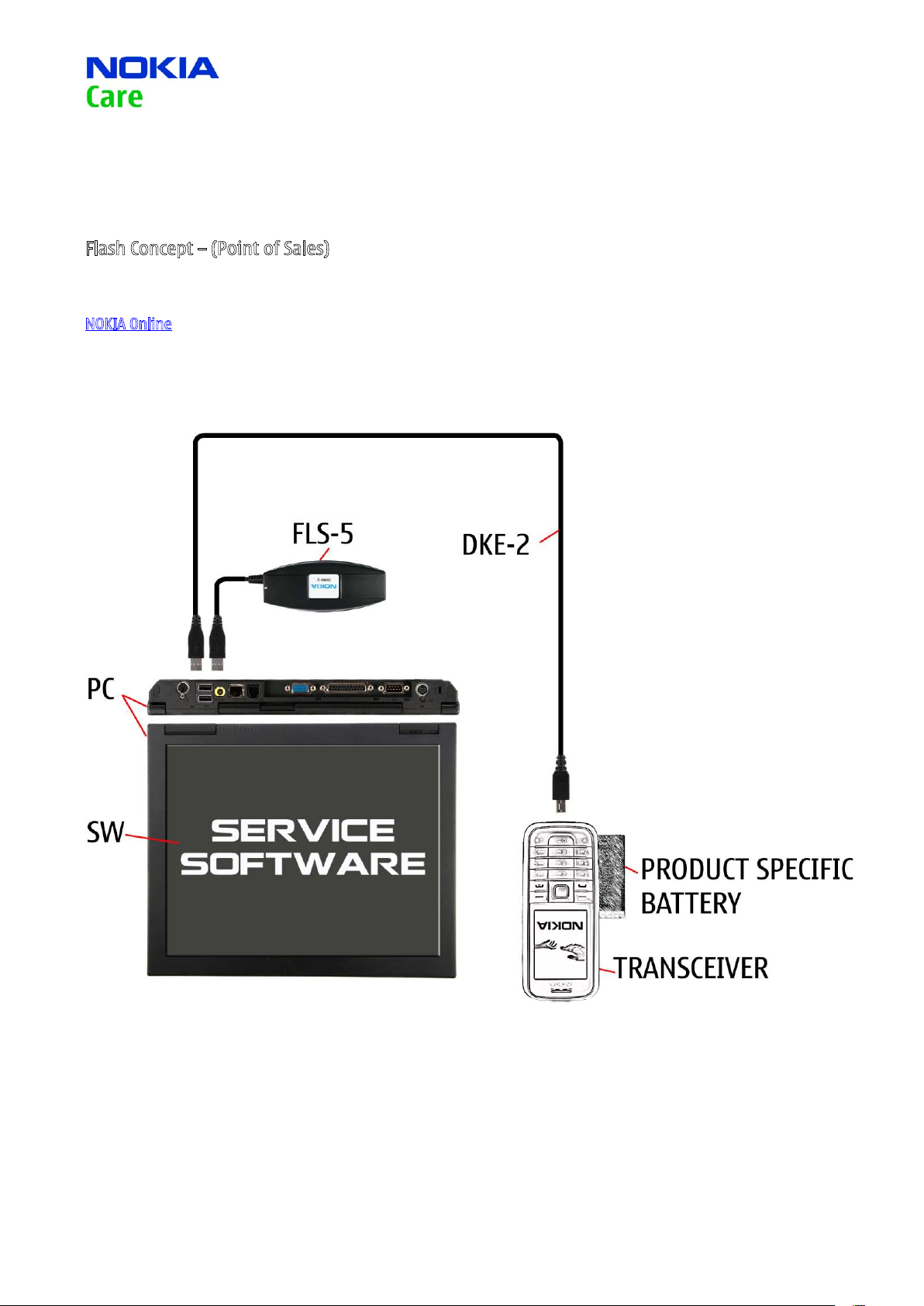
DKE-2
Service Cable to connect the PC with the mini USB connector.
Service Manual 6290 RM-176 Copyright © 2007 NOKIA Corporation. All rights reserved.
Page 10
Page
CMO Operations & Logistics
Training and Vendor Development
Multimedia Creation & Support CONFIDENTIAL
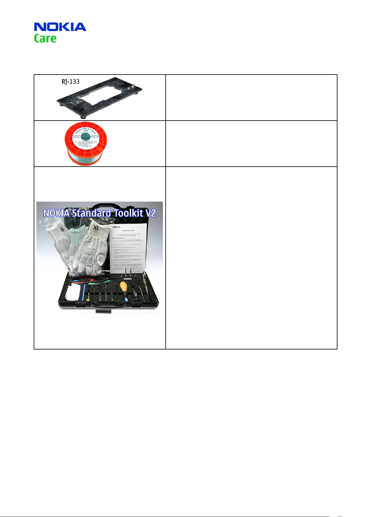
RJ-133
Soldering Jig
Lead-free Solder Wire
Mandatory for lead-free products (Level 2 only).
10
(45)
Approved 2.0
MGR
13.Apr.2007
0772040 NMP Standard Toolkit (V2)
For more informations refer to the Service Bulletin (SB-011) on
NOKIA Online.
Supplier or manufacturer contacts for tool re-order can be
found in “Recommended service equipment” document on
NOKIA Online.
Service Manual 6290 RM-176 Copyright © 2007 NOKIA Corporation. All rights reserved.
Page 11
(45)
Page
CMO Operations & Logistics
Training and Vendor Development
Multimedia Creation & Support CONFIDENTIAL
11
Approved 2.0
13.Apr.2007
SW-UPDATE8.
Flash Concept – (Point of Sales)
To use FLS-5 Flash Dongle you have to follow the user guide inside the sales package. Please check always for the
latest version of flash software, which is available on
NOKIA Online.
MGR
Service Manual 6290 RM-176 Copyright © 2007 NOKIA Corporation. All rights reserved.
Page 12
Page
12
CMO Operations & Logistics
Training and Vendor Development
Multimedia Creation & Support CONFIDENTIAL
UPPER BLOCK DISASSEMBLY9.
(45)
Approved 2.0
MGR
13.Apr.2007
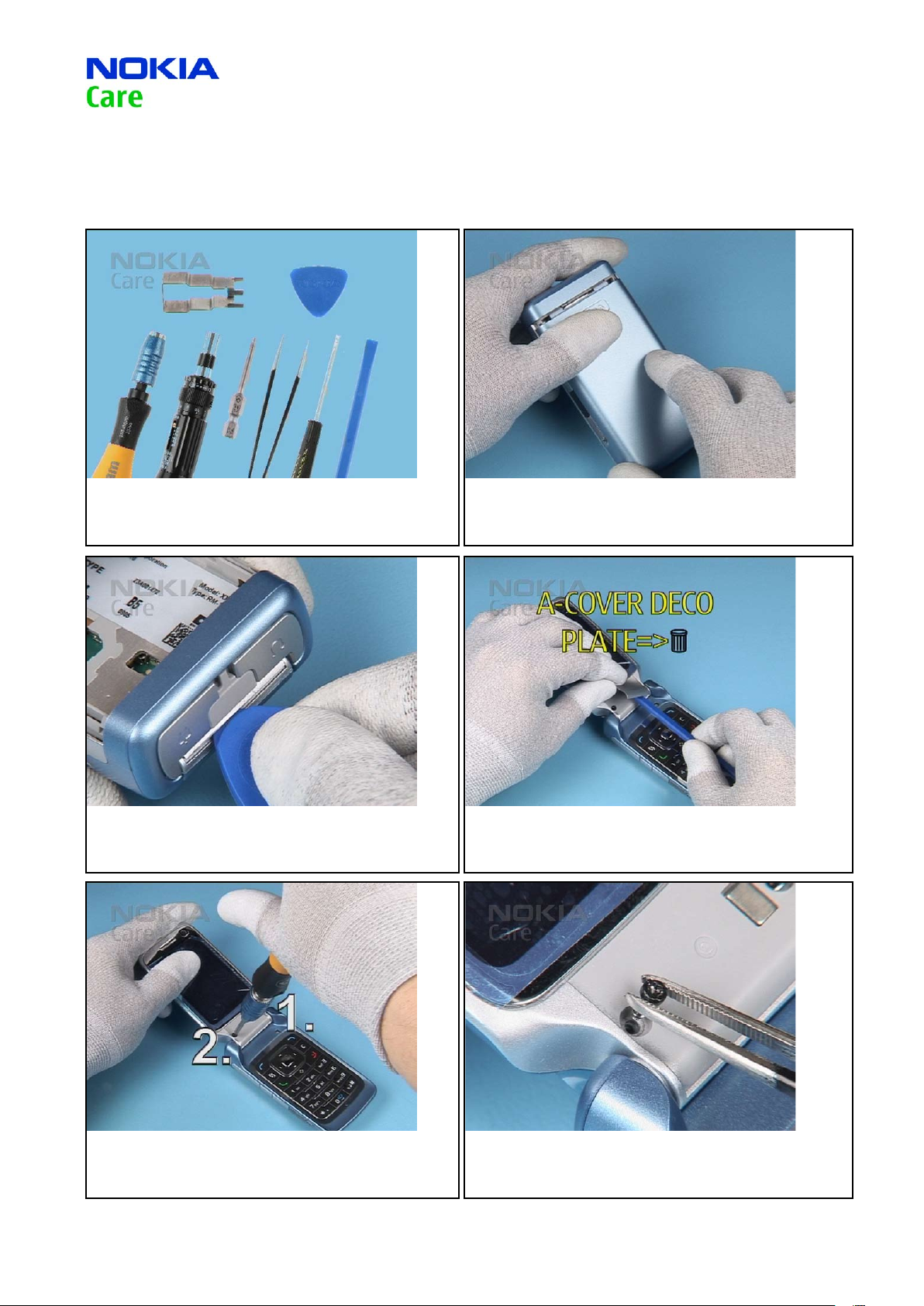
1. Needed tools : A Torx and a torque driver, a Torx Plus size 6
bit, metal tweezers, a at bladed screwdriver, the SS-93, the
SRT-6 and the SS-102 camera removal tool.
3. First, place the SRT-6 between the edge of the A-COVER
UPPER and the A-COVER DECO PLATE and gently slide it along
the edge.
2. Open and remove the BATTERY COVER. Remove the battery if
inserted.
4. Then remove the A-COVER DECO PLATE with the SS-93 and
discard it.
5. Unscrew the screws in the order shown.
6. Remove the screws.
Service Manual 6290 RM-176 Copyright © 2007 NOKIA Corporation. All rights reserved.
Page 13
Page
13
CMO Operations & Logistics
Training and Vendor Development
Multimedia Creation & Support CONFIDENTIAL
(45)
Approved 2.0
MGR
13.Apr.2007
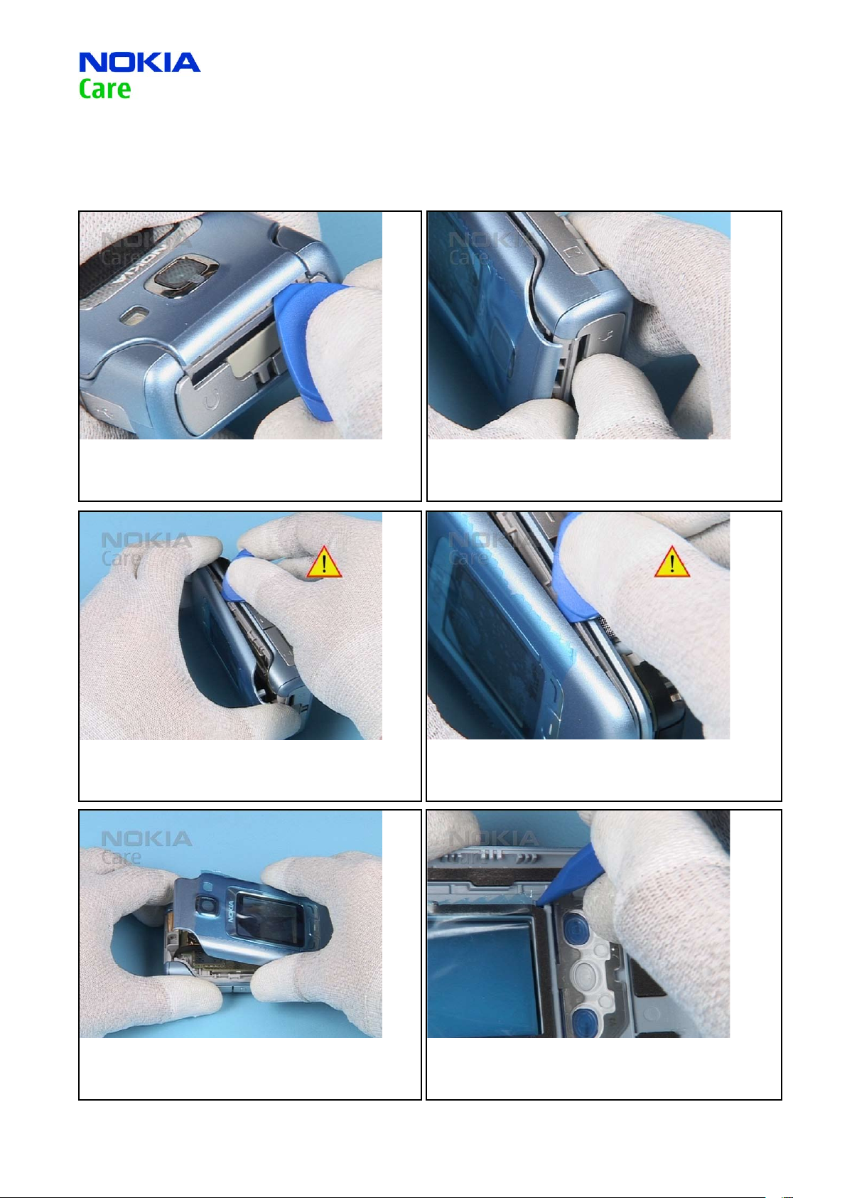
7. Unlock the snaps of the B-COVER UPPER starting on the
shown side.
9. …and gently slide the SRT-6 along the edge to unlock the
snaps. Do not twist the SRT-6 to avoid scratching the covers.
8. Expand the B-COVER UPPER from the shown side…
10. Do the same on the other side.
11. Remove the B-COVER UPPER.
12. Unlock the snaps of the UI KEYMAT with the SS-93…
Service Manual 6290 RM-176 Copyright © 2007 NOKIA Corporation. All rights reserved.
Page 14
Page (45)
14
CMO Operations & Logistics
Training and Vendor Development
Multimedia Creation & Support CONFIDENTIAL
Approved 2.0
MGR
13.Apr.2007
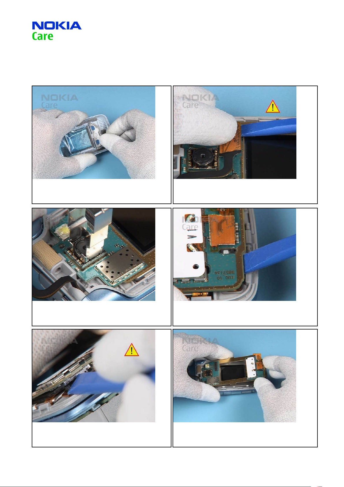
13. ...and remove it from the B-COVER UPPER.
15. Carefully, remove the CAMERA MODULE with the SS-102.
14. Gently, open the PWB FLEX connector.
16. Unlock the UI BOARD…
17. …and carefully open the LCD connector.
18. Now, remove the UI BOARD ASSY from the A-COVER UPPER.
Service Manual 6290 RM-176 Copyright © 2007 NOKIA Corporation. All rights reserved.
Page 15

Page (45)
15
CMO Operations & Logistics
Training and Vendor Development
Multimedia Creation & Support CONFIDENTIAL
Approved 2.0
MGR
13.Apr.2007
19. Cover the SUB DISPLAY with the protective lm.
21. Cover the MAIN DISPLAY with the protective lm.
20. Now, the displays can be removed easily.
22. Use the at bladed screwdriver as a lever to unlock the
EARPIECE from its place...
23. …and remove it.
24. Open the UI FLEX connector.
Service Manual 6290 RM-176 Copyright © 2007 NOKIA Corporation. All rights reserved.
Page 16

Page (45)
16
CMO Operations & Logistics
Training and Vendor Development
Multimedia Creation & Support CONFIDENTIAL
Approved 2.0
MGR
13.Apr.2007
25. Remove the UI FLEX from the UI BOARD and discard it.
26. The disassembly procedure is now completed.
Service Manual 6290 RM-176 Copyright © 2007 NOKIA Corporation. All rights reserved.
Page 17

Page
17
CMO Operations & Logistics
Training and Vendor Development
Multimedia Creation & Support CONFIDENTIAL
UPPER BLOCK ASSEMBLY 10.
(45)
Approved 2.0
MGR
13.Apr.2007
1. Place the EARPIECE into the A-COVER UPPER…
3. Align the new UI FLEX with the UI BOARD…
2. …and gently push it into its place. Avoid bending the spring
contacts.
4. …and close the connector.
5. Note the right position of the UI FLEX…
6. …and press it carefully onto the metal shield.
Service Manual 6290 RM-176 Copyright © 2007 NOKIA Corporation. All rights reserved.
Page 18

Page
18
CMO Operations & Logistics
Training and Vendor Development
Multimedia Creation & Support CONFIDENTIAL
(45)
Approved 2.0
MGR
13.Apr.2007
7. Place the LCD into the A-COVER UPPER.
9. Align the UI BOARD with the A-COVER UPPER, secureit into ist
position…
8. Ensure the right position of the LCD connector.
10. …and carefully close the LCD connector.
11. Ensure that the CAMERA MODULE CIF is positioned correctly.
12. Insert the CAMERA MODULE. Note the right position of the
guide pin.
Service Manual 6290 RM-176 Copyright © 2007 NOKIA Corporation. All rights reserved.
Page 19

Page
19
CMO Operations & Logistics
Training and Vendor Development
Multimedia Creation & Support CONFIDENTIAL
(45)
Approved 2.0
MGR
13.Apr.2007
13. Secure the CAMERA MODULE by gently pressing it into place.
15. Fit the UI KEYMAT and close the snaps.
14. Close the PWB FLEX connector.
16. Fit the B-COVER UPPER...
17. and carefully squeeze the parts together.
18. Insert the screws.
Service Manual 6290 RM-176 Copyright © 2007 NOKIA Corporation. All rights reserved.
Page 20

Page
20
CMO Operations & Logistics
Training and Vendor Development
Multimedia Creation & Support CONFIDENTIAL
(45)
Approved 2.0
MGR
13.Apr.2007
19. Set the torque driver to the correct torque.
21. Then tighten them in the order shown.
20. To avoid damaging of the plastic threads rst tighten the
screws to the left.
22. Place the A-COVER DECO PLATE onto the A-COVER UPPER and
press it carefully to secure it into its place.
23. Check that no gaps remain.
24. Finally, t the BATTERY COVER.
Service Manual 6290 RM-176 Copyright © 2007 NOKIA Corporation. All rights reserved.
Page 21

Page
21
CMO Operations & Logistics
Training and Vendor Development
Multimedia Creation & Support CONFIDENTIAL
LOWER BLOCK DISASSEMBLY11.
(45)
Approved 2.0
MGR
13.Apr.2007
1. Needed tools: A Torx and a torque driver, a Torx Plus size 6
bit, metal tweezers, the SS-93, the SRT-6 and the DC-plug.
3. Open the unit.
2. Open and remove the BATTERY COVER. Remove the Battery if
inserted.
4. Place the SRT-6 between the KEYMAT and the A-COVER LOWER
and carefully slide it along the edge as shown.
5. Remove the KEYMAT avoiding to touch the LEDs.
6. Close the unit.
Service Manual 6290 RM-176 Copyright © 2007 NOKIA Corporation. All rights reserved.
Page 22

Page
22
CMO Operations & Logistics
Training and Vendor Development
Multimedia Creation & Support CONFIDENTIAL
(45)
Approved 2.0
MGR
13.Apr.2007
7. Unlock the snaps of the TOP CAP ASSY with the SS-93.
9. Unscrew the 4 Torx Plus size six screws in the order shown.
8. Remove the TOP CAP ASSY.
10. Remove the screws.
11. Place the SRT-6 between the C-COVER ASSY and the A-COVER
LOWER and carefully release the snaps.
12. Lift the A-COVER LOWER as shown…
Service Manual 6290 RM-176 Copyright © 2007 NOKIA Corporation. All rights reserved.
Page 23

Page
23
CMO Operations & Logistics
Training and Vendor Development
Multimedia Creation & Support CONFIDENTIAL
(45)
Approved 2.0
MGR
13.Apr.2007
13. …and carefully open the Hinge PWB FLEX connector with
the SS-93.
15. … and remove it from the C-COVER ASSY.
14. Unlock the ENGINE MODULE as shown…
16. Remove the ANTENNA.
17. Remove the IHF ASSEMBLY from the C-COVER ASSEMBLY.
18. Remove the MICRO SD LID…
Service Manual 6290 RM-176 Copyright © 2007 NOKIA Corporation. All rights reserved.
Page 24

Page
24
CMO Operations & Logistics
Training and Vendor Development
Multimedia Creation & Support CONFIDENTIAL
(45)
Approved 2.0
MGR
13.Apr.2007
19. … and the MINI USB LID.
21. Use the SS-93 as a lever to lift the IHF SPEAKER from the IHF
ASSEMBLY.
20. Use the DC-plug to remove the DC-JACK.
22. Now, remove the IHF SPEAKER. Do the same on the other side.
23. Open the A-COVER ASSY as shown…
24. …and remove the PWB FLEX from the HINGE.
Service Manual 6290 RM-176 Copyright © 2007 NOKIA Corporation. All rights reserved.
Page 25

Page
25
CMO Operations & Logistics
Training and Vendor Development
Multimedia Creation & Support CONFIDENTIAL
(45)
Approved 2.0
MGR
13.Apr.2007
25. Note the right position of the PWB FLEX when assembling
the unit.
27. Close the A-COVER ASSY…
26. Carefully insert the PWB FLEX into the HINGE slot.
28. …and check if the PWB ex is positioned correctly.
29. The disassembly procedure is now completed.
Service Manual 6290 RM-176 Copyright © 2007 NOKIA Corporation. All rights reserved.
Page 26

Page
26
CMO Operations & Logistics
Training and Vendor Development
Multimedia Creation & Support CONFIDENTIAL
LOWER BLOCK DISASSEMBLY 12.
(45)
Approved 2.0
MGR
13.Apr.2007
1. Insert the IHF SPEAKERs into the IHF ASSEMBLY avoiding to
touch the spring contacts and the membrane of the speaker.
3. Insert the MINI USB LID and close it.
2. Insert the DC-JACK with the DC-plug into the A-COVER ASSY.
Avoid bending the spring contacts.
4. Insert the MICRO-SD LID and close it.
5. Align the IHF ASSEMBLY with the C-COVER ASSY as shown…
6. …and secure it by carefully pressing it into position.
Service Manual 6290 RM-176 Copyright © 2007 NOKIA Corporation. All rights reserved.
Page 27

Page
27
CMO Operations & Logistics
Training and Vendor Development
Multimedia Creation & Support CONFIDENTIAL
(45)
Approved 2.0
MGR
13.Apr.2007
7. Gently connect the PWB FLEX to the ENGINE MODULE.
9. Note the right position of the guide pins.
8. Place the ENGINE MODULE onto the A-COVER UPPER.
10. Align the C-COVER ASSY with the A-COVER LOWER.
11. Secure the parts by carefully squeezing them together.
12. Fit the ANTENNA to the C-COVER ASSEMBLY…
Service Manual 6290 RM-176 Copyright © 2007 NOKIA Corporation. All rights reserved.
Page 28

Page
28
CMO Operations & Logistics
Training and Vendor Development
Multimedia Creation & Support CONFIDENTIAL
(45)
Approved 2.0
MGR
13.Apr.2007
13. …and close the shown snap.
15. Set the torque driver to the correct torque.
14. Insert the screws.
16. To avoid damaging the plastic threads, rst tighten the
screws to the left.
17. Then tighten them in the order shown.
18. Fit the TOP CAP ASSY…
Service Manual 6290 RM-176 Copyright © 2007 NOKIA Corporation. All rights reserved.
Page 29

Page
29
CMO Operations & Logistics
Training and Vendor Development
Multimedia Creation & Support CONFIDENTIAL
(45)
Approved 2.0
MGR
13.Apr.2007
19. …secure it by pressing it into position.
21. …and t the KEYMAT into the A-COVER LOWER.
20. Open the unit …
22. Check the correct position of the KEYMAT.
23. Fit the BATTERY COVER.
24. Finally, check that no gaps remain.
Service Manual 6290 RM-176 Copyright © 2007 NOKIA Corporation. All rights reserved.
Page 30

Page
CMO Operations & Logistics
Training and Vendor Development
Multimedia Creation & Support CONFIDENTIAL
30
LEGEND FOR QUICK TROUBLE SHOOTER13.
(45)
Approved 2.0
MGR
13.Apr.2007
Service Manual 6290 RM-176 Copyright © 2007 NOKIA Corporation. All rights reserved.
Page 31

Page
CMO Operations & Logistics
Training and Vendor Development
Multimedia Creation & Support CONFIDENTIAL
31
QUICK TROUBLE SHOOTER - POWER ON14.
(45)
Approved 2.0
MGR
13.Apr.2007
Service Manual 6290 RM-176 Copyright © 2007 NOKIA Corporation. All rights reserved.
Page 32

Page
CMO Operations & Logistics
Training and Vendor Development
Multimedia Creation & Support CONFIDENTIAL
32
QUICK TROUBLE SHOOTER - CHARGING15.
(45)
Approved 2.0
MGR
13.Apr.2007
Service Manual 6290 RM-176 Copyright © 2007 NOKIA Corporation. All rights reserved.
Page 33

Page
CMO Operations & Logistics
Training and Vendor Development
Multimedia Creation & Support CONFIDENTIAL
33
QUICK TROUBLE SHOOTER - NO SERVICE16.
(45)
Approved 2.0
MGR
13.Apr.2007
Service Manual 6290 RM-176 Copyright © 2007 NOKIA Corporation. All rights reserved.
Page 34

Page
CMO Operations & Logistics
Training and Vendor Development
Multimedia Creation & Support CONFIDENTIAL
34
QUICK TROUBLE SHOOTER - BLUETOOTH17.
(45)
Approved 2.0
MGR
13.Apr.2007
Service Manual 6290 RM-176 Copyright © 2007 NOKIA Corporation. All rights reserved.
Page 35

Page
CMO Operations & Logistics
Training and Vendor Development
Multimedia Creation & Support CONFIDENTIAL
35
QUICK TROUBLE SHOOTER - EARPIECE18.
(45)
Approved 2.0
MGR
13.Apr.2007
Service Manual 6290 RM-176 Copyright © 2007 NOKIA Corporation. All rights reserved.
Page 36

Page
CMO Operations & Logistics
Training and Vendor Development
Multimedia Creation & Support CONFIDENTIAL
36
QUICK TROUBLE SHOOTER - IHF SPEAKER 19.
(45)
Approved 2.0
MGR
13.Apr.2007
Service Manual 6290 RM-176 Copyright © 2007 NOKIA Corporation. All rights reserved.
Page 37

Page
CMO Operations & Logistics
Training and Vendor Development
Multimedia Creation & Support CONFIDENTIAL
37
QUICK TROUBLE SHOOTER - DISPLAY 20.
(45)
Approved 2.0
MGR
13.Apr.2007
Service Manual 6290 RM-176 Copyright © 2007 NOKIA Corporation. All rights reserved.
Page 38

Page
CMO Operations & Logistics
Training and Vendor Development
Multimedia Creation & Support CONFIDENTIAL
38
QUICK TROUBLE SHOOTER - MICROPHONE 21.
(45)
Approved 2.0
MGR
13.Apr.2007
Service Manual 6290 RM-176 Copyright © 2007 NOKIA Corporation. All rights reserved.
Page 39

Page
CMO Operations & Logistics
Training and Vendor Development
Multimedia Creation & Support CONFIDENTIAL
39
QUICK TROUBLE SHOOTER - KEYMAT 22.
(45)
Approved 2.0
MGR
13.Apr.2007
Service Manual 6290 RM-176 Copyright © 2007 NOKIA Corporation. All rights reserved.
Page 40

Page (45)
CMO Operations & Logistics
Training and Vendor Development
Multimedia Creation & Support CONFIDENTIAL
40
QUICK TROUBLE SHOOTER - UI KEYMAT23.
Approved 2.0
MGR
13.Apr.2007
Service Manual 6290 RM-176 Copyright © 2007 NOKIA Corporation. All rights reserved.
Page 41

Page
CMO Operations & Logistics
Training and Vendor Development
Multimedia Creation & Support CONFIDENTIAL
41
QUICK TROUBLE SHOOTER - PUSH TO TALK 24.
(45)
Approved 2.0
MGR
13.Apr.2007
Service Manual 6290 RM-176 Copyright © 2007 NOKIA Corporation. All rights reserved.
Page 42

Page
CMO Operations & Logistics
Training and Vendor Development
Multimedia Creation & Support CONFIDENTIAL
42
QUICK TROUBLE SHOOTER - VOLUME KEYS25.
(45)
Approved 2.0
MGR
13.Apr.2007
Service Manual 6290 RM-176 Copyright © 2007 NOKIA Corporation. All rights reserved.
Page 43

Page
CMO Operations & Logistics
Training and Vendor Development
Multimedia Creation & Support CONFIDENTIAL
43
QUICK TROUBLE SHOOTER - CARD READER26.
(45)
Approved 2.0
MGR
13.Apr.2007
Service Manual 6290 RM-176 Copyright © 2007 NOKIA Corporation. All rights reserved.
Page 44

Page
CMO Operations & Logistics
Training and Vendor Development
Multimedia Creation & Support CONFIDENTIAL
44
QUICK TROUBLE SHOOTER - CAMERA27.
(45)
Approved 2.0
MGR
13.Apr.2007
Service Manual 6290 RM-176 Copyright © 2007 NOKIA Corporation. All rights reserved.
Page 45

Page
CMO Operations & Logistics
Training and Vendor Development
Multimedia Creation & Support CONFIDENTIAL
45
QUICK TROUBLE SHOOTER - CAMERA CIF28.
(45)
Approved 2.0
MGR
13.Apr.2007
Service Manual 6290 RM-176 Copyright © 2007 NOKIA Corporation. All rights reserved.
 Loading...