

Page 1

Nokia Customer Care
Service Manual
RM-159 (Nokia N95)
Mobile Terminal
Part No: 9200120 (Issue 1)
COMPANY CONFIDENTIAL
Copyright © 2007 Nokia. All rights reserved.
Page 2

RM-159
Nokia Customer Care Amendment Record Sheet
Amendment Record Sheet
Amendment No Date Inserted By Comments
Issue 1 01/2007 M. Hautaniemi
Page ii COMPANY CONFIDENTIAL Issue 1
Copyright © 2007 Nokia. All rights reserved.
Page 3

RM-159
Copyright Nokia Customer Care
Copyright
Copyright © 2007 Nokia. All rights reserved.
Reproduction, transfer, distribution or storage of part or all of the contents in this document in any form
without the prior written permission of Nokia is prohibited.
Nokia, Nokia Connecting People, and Nokia X and Y are trademarks or registered trademarks of Nokia
Corporation. Other product and company names mentioned herein may be trademarks or tradenames of
their respective owners.
Nokia operates a policy of continuous development. Nokia reserves the right to make changes and
improvements to any of the products described in this document without prior notice.
Under no circumstances shall Nokia be responsible for any loss of data or income or any special, incidental,
consequential or indirect damages howsoever caused.
The contents of this document are provided "as is". Except as required by applicable law, no warranties of
any kind, either express or implied, including, but not limited to, the implied warranties of merchantability
and fitness for a particular purpose, are made in relation to the accuracy, reliability or contents of this
document. Nokia reserves the right to revise this document or withdraw it at any time without prior notice.
The availability of particular products may vary by region.
IMPORTANT
This document is intended for use by qualified service personnel only.
Issue 1 COMPANY CONFIDENTIAL Page iii
Copyright © 2007 Nokia. All rights reserved.
Page 4

RM-159
Nokia Customer Care Warnings and cautions
Warnings and cautions
Warnings
• IF THE DEVICE CAN BE INSTALLED IN A VEHICLE, CARE MUST BE TAKEN ON INSTALLATION IN VEHICLES FITTED
WITH ELECTRONIC ENGINE MANAGEMENT SYSTEMS AND ANTI-SKID BRAKING SYSTEMS. UNDER CERTAIN FAULT
CONDITIONS, EMITTED RF ENERGY CAN AFFECT THEIR OPERATION. IF NECESSARY, CONSULT THE VEHICLE DEALER/
MANUFACTURER TO DETERMINE THE IMMUNITY OF VEHICLE ELECTRONIC SYSTEMS TO RF ENERGY.
• THE PRODUCT MUST NOT BE OPERATED IN AREAS LIKELY TO CONTAIN POTENTIALLY EXPLOSIVE ATMOSPHERES,
FOR EXAMPLE, PETROL STATIONS (SERVICE STATIONS), BLASTING AREAS ETC.
• OPERATION OF ANY RADIO TRANSMITTING EQUIPMENT, INCLUDING CELLULAR TELEPHONES, MAY INTERFERE
WITH THE FUNCTIONALITY OF INADEQUATELY PROTECTED MEDICAL DEVICES. CONSULT A PHYSICIAN OR THE
MANUFACTURER OF THE MEDICAL DEVICE IF YOU HAVE ANY QUESTIONS. OTHER ELECTRONIC EQUIPMENT MAY
ALSO BE SUBJECT TO INTERFERENCE.
• BEFORE MAKING ANY TEST CONNECTIONS, MAKE SURE YOU HAVE SWITCHED OFF ALL EQUIPMENT.
Cautions
• Servicing and alignment must be undertaken by qualified personnel only.
• Ensure all work is carried out at an anti-static workstation and that an anti-static wrist strap is worn.
• Ensure solder, wire, or foreign matter does not enter the telephone as damage may result.
• Use only approved components as specified in the parts list.
• Ensure all components, modules, screws and insulators are correctly re-fitted after servicing and
alignment.
• Ensure all cables and wires are repositioned correctly.
• Never test a mobile phone WCDMA transmitter with full Tx power, if there is no possibility to perform the
measurements in a good performance RF-shielded room. Even low power WCDMA transmitters may disturb
nearby WCDMA networks and cause problems to 3G cellular phone communication in a wide area.
• During testing never activate the GSM or WCDMA transmitter without a proper antenna load, otherwise
GSM or WCDMA PA may be damaged.
Page iv COMPANY CONFIDENTIAL Issue 1
Copyright © 2007 Nokia. All rights reserved.
Page 5

RM-159
ESD protection Nokia Customer Care
ESD protection
Nokia requires that service points have sufficient ESD protection (against static electricity) when servicing
the phone.
Any product of which the covers are removed must be handled with ESD protection. The SIM card can be
replaced without ESD protection if the product is otherwise ready for use.
To replace the covers ESD protection must be applied.
All electronic parts of the product are susceptible to ESD. Resistors, too, can be damaged by static electricity
discharge.
All ESD sensitive parts must be packed in metallized protective bags during shipping and handling outside
any ESD Protected Area (EPA).
Every repair action involving opening the product or handling the product components must be done under
ESD protection.
ESD protected spare part packages MUST NOT be opened/closed out of an ESD Protected Area.
For more information and local requirements about ESD protection and ESD Protected Area, contact your local
Nokia After Market Services representative.
Issue 1 COMPANY CONFIDENTIAL Page v
Copyright © 2007 Nokia. All rights reserved.
Page 6

RM-159
Nokia Customer Care Care and maintenance
Care and maintenance
This product is of superior design and craftsmanship and should be treated with care. The suggestions below
will help you to fulfil any warranty obligations and to enjoy this product for many years.
• Keep the phone and all its parts and accessories out of the reach of small children.
• Keep the phone dry. Precipitation, humidity and all types of liquids or moisture can contain minerals that
will corrode electronic circuits.
• Do not use or store the phone in dusty, dirty areas. Its moving parts can be damaged.
• Do not store the phone in hot areas. High temperatures can shorten the life of electronic devices, damage
batteries, and warp or melt certain plastics.
• Do not store the phone in cold areas. When it warms up (to its normal temperature), moisture can form
inside, which may damage electronic circuit boards.
• Do not drop, knock or shake the phone. Rough handling can break internal circuit boards.
• Do not use harsh chemicals, cleaning solvents, or strong detergents to clean the phone.
• Do not paint the phone. Paint can clog the moving parts and prevent proper operation.
• Use only the supplied or an approved replacement antenna. Unauthorised antennas, modifications or
attachments could damage the phone and may violate regulations governing radio devices.
All of the above suggestions apply equally to the product, battery, charger or any accessory.
Page vi COMPANY CONFIDENTIAL Issue 1
Copyright © 2007 Nokia. All rights reserved.
Page 7

RM-159
Company Policy Nokia Customer Care
Company Policy
Our policy is of continuous development; details of all technical modifications will be included with service
bulletins.
While every endeavour has been made to ensure the accuracy of this document, some errors may exist. If
any errors are found by the reader, NOKIA MOBILE PHONES Business Group should be notified in writing/email.
Please state:
• Title of the Document + Issue Number/Date of publication
• Latest Amendment Number (if applicable)
• Page(s) and/or Figure(s) in error
Please send to:
NOKIA CORPORATION
Nokia Mobile Phones Business Group
Nokia Customer Care
PO Box 86
FIN-24101 SALO
Finland
E-mail: Service.Manuals@nokia.com
Issue 1 COMPANY CONFIDENTIAL Page vii
Copyright © 2007 Nokia. All rights reserved.
Page 8

RM-159
Nokia Customer Care Battery information
Battery information
Note: A new battery's full performance is achieved only after two or three complete charge and
discharge cycles!
The battery can be charged and discharged hundreds of times but it will eventually wear out. When the
operating time (talk-time and standby time) is noticeably shorter than normal, it is time to buy a new battery.
Use only batteries approved by the phone manufacturer and recharge the battery only with the chargers
approved by the manufacturer. Unplug the charger when not in use. Do not leave the battery connected to
a charger for longer than a week, since overcharging may shorten its lifetime. If left unused a fully charged
battery will discharge itself over time.
Temperature extremes can affect the ability of your battery to charge.
For good operation times with Ni-Cd/NiMh batteries, discharge the battery from time to time by leaving the
product switched on until it turns itself off (or by using the battery discharge facility of any approved accessory
available for the product). Do not attempt to discharge the battery by any other means.
Use the battery only for its intended purpose.
Never use any charger or battery which is damaged.
Do not short-circuit the battery. Accidental short-circuiting can occur when a metallic object (coin, clip or
pen) causes direct connection of the + and - terminals of the battery (metal strips on the battery) for example
when you carry a spare battery in your pocket or purse. Short-circuiting the terminals may damage the battery
or the connecting object.
Leaving the battery in hot or cold places, such as in a closed car in summer or winter conditions, will reduce
the capacity and lifetime of the battery. Always try to keep the battery between 15°C and 25°C (59°F and 77°
F). A phone with a hot or cold battery may temporarily not work, even when the battery is fully charged.
Batteries' performance is particularly limited in temperatures well below freezing.
Do not dispose of batteries in a fire!
Dispose of batteries according to local regulations (e.g. recycling). Do not dispose as household waste.
Page viii COMPANY CONFIDENTIAL Issue 1
Copyright © 2007 Nokia. All rights reserved.
Page 9

RM-159
Nokia N95 Service Manual Structure Nokia Customer Care
Nokia N95 Service Manual Structure
1 General Information
2 Parts Lists and Component Layouts
3 Service Software Instructions
4 Service Tools and Service Concepts
5 Disassembly and reassembly instructions
6 BB Troubleshooting and Tuning Guide
7 RF troubleshooting
8 Camera Module Troubleshooting
9 System Module
10 Schematics
Issue 1 COMPANY CONFIDENTIAL Page ix
Copyright © 2007 Nokia. All rights reserved.
Page 10

RM-159
Nokia Customer Care Nokia N95 Service Manual Structure
(This page left intentionally blank.)
Page x COMPANY CONFIDENTIAL Issue 1
Copyright © 2007 Nokia. All rights reserved.
Page 11

Nokia Customer Care
1 — General Information
Issue 1 COMPANY CONFIDENTIAL Page 1 –1
Copyright © 2007 Nokia. All rights reserved.
Page 12

RM-159
Nokia Customer Care General Information
(This page left intentionally blank.)
Page 1 –2 COMPANY CONFIDENTIAL Issue 1
Copyright © 2007 Nokia. All rights reserved.
Page 13

RM-159
General Information Nokia Customer Care
Table of Contents
RM-159 product selection......................................................................................................................................1–5
RM-159 product features and sales package.......................................................................................................1–5
Mobile enhancements............................................................................................................................................1–8
Technical specifications...................................................................................................................................... 1–10
Transceiver general specifications ............................................................................................................... 1–10
Main RF characteristics for GSM850/900/1800/1900 and WCDMA 2100 phones ..................................... 1–10
Battery endurance.......................................................................................................................................... 1–11
List of Tables
Table 1 Audio..........................................................................................................................................................1–8
Table 2 Car...............................................................................................................................................................1–9
Table 3 Data ............................................................................................................................................................1–9
Table 4 GPS........................................................................................................................................................... 1–10
Table 5 Messaging............................................................................................................................................... 1–10
Table 6 Power...................................................................................................................................................... 1–10
Table 7 Carrying................................................................................................................................................... 1–10
List of Figures
Figure 1 View of RM-159........................................................................................................................................1–5
Issue 1 COMPANY CONFIDENTIAL Page 1 –3
Copyright © 2007 Nokia. All rights reserved.
Page 14

RM-159
Nokia Customer Care General Information
(This page left intentionally blank.)
Page 1 –4 COMPANY CONFIDENTIAL Issue 1
Copyright © 2007 Nokia. All rights reserved.
Page 15
RM-159
General Information Nokia Customer Care
RM-159 product selection
RM-159 is a WCDMA/GSM dual mode handportable phone, supporting EGSM850/900/1800/1900 and
WCDMA2100.
RM-159 is a 3GPP Release 5 terminal supporting WCDMA/HSDPA, EGPRS and GPRS data bearers. For WCDMA
HSDPA the maximum bit rate is up to 3.6 Mbps for downlink and 384 kbps for uplink with simultaneous CS
speech or CS video (max. 64 kbps).
For 2G and 2.5G networks the RM-159 is a Class A EGPRS DTM MSC 11 which means maximum download speed
of up to 236.8 kbps simultaneously with speech or Class B EGPRS MSC 32 which means a in maximum download
speed of up to 296kbit/s with EGPRS, and up to 107kbit/s with GPRS.
According to GSM standard 05.05 it responds to class 4 (max. 2W) in GSM 850 and EGSM 900 class 1 (1W) in
DCS 1800 and class 1 in PCS 1900. RM-159 supports EGPRS (EDGE) class B as well as Bluetooth 2.0 EDR standard.
RM-159 supports two way video calls with two integrated cameras, one on the front and one on the back.
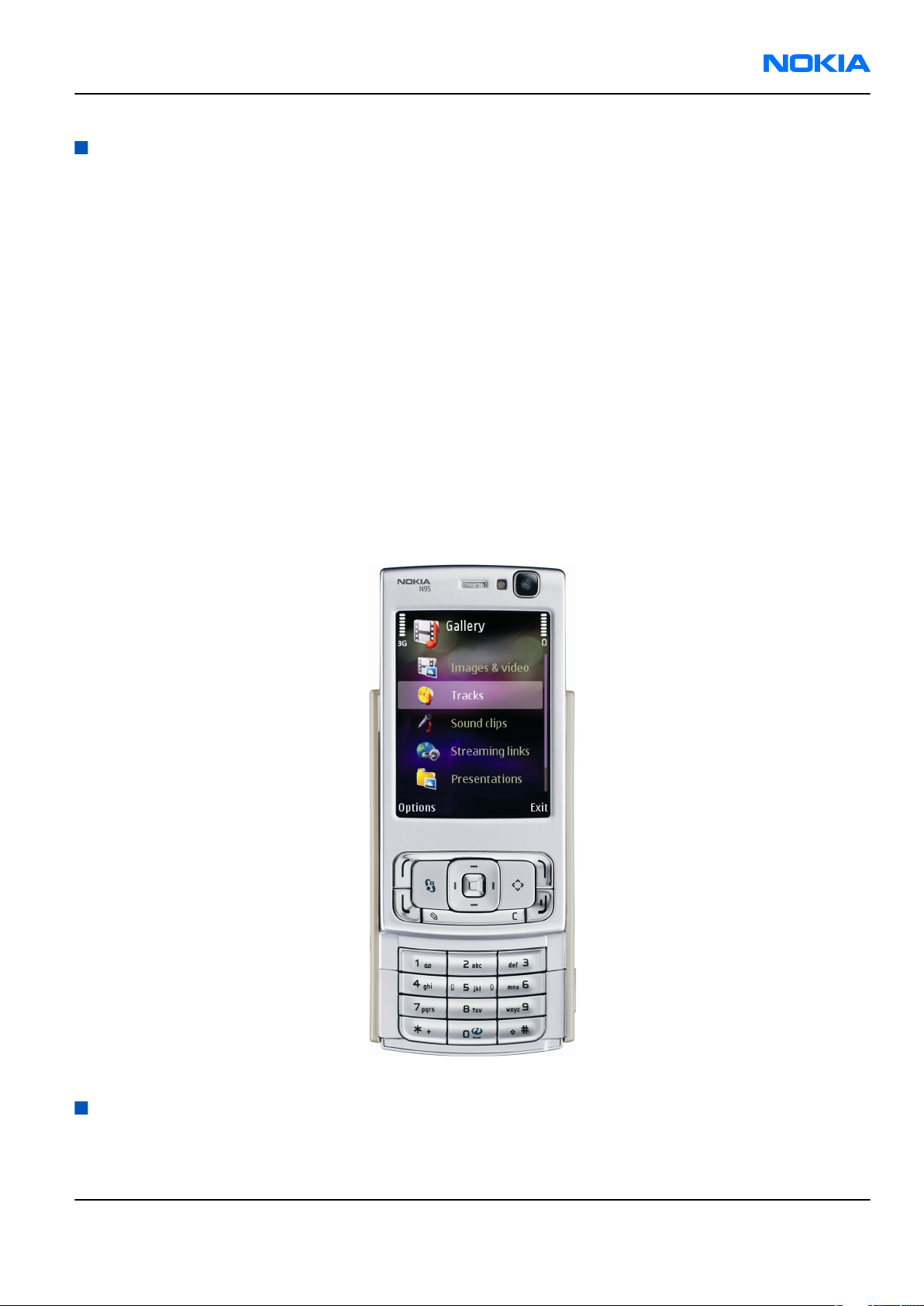
RM-159 is an MMS (Multimedia Messaging Service) enabled multimedia computer with a large 2.6’’ QVGA (240
x 320 pixels) TFT colour display and an integrated 5 Megapixel auto focus camera. The MMS implementation
follows the OMA MMS standard release 1.2. The Browser is a highly advanced internet browser also capable
of viewing operator domain XHTML Mobile Profile (MP) content.
RM-159 uses Symbian 9.2 operating system and supports also MIDP Java 2.0 & CLDC1.1, providing a good
platform for compelling 3rd party applications.
Figure 1 View of RM-159
RM-159 product features and sales package
Imaging
Main camera:
Issue 1 COMPANY CONFIDENTIAL Page 1 –5
Copyright © 2007 Nokia. All rights reserved.
Page 16

RM-159
Nokia Customer Care General Information
• Sensor: CMOS, 5 megapixel
• Carl Zeiss Optics: Tessar™ lens
• F number/Aperture: F2.8
• Focal length: 5.6 mm
35 mm (35 mm equiv.)
• Focus range: 10 cm ~ infinity
• Macro focus distance: 10-50 cm
• Shutter speed: Mechanical shutter 1/1000~1/4 s
• Lens protection: Sliding cover with activation
Video:
• Video resolution: up to VGA at 30 fps
• Audio recording: AAC (AMR for MMS)
• Video stabilization
• Video clip length: 59 min 59 sec
• Video file format: .mp4 (default) , .3gp (for MMS)
• White balance: automatic, sunny, cloudy, incandescent, fluorescent
• Scene: Auto, Night
• Colour tone: normal, sepia, B&W, vivid, negative
• Zoom (optical/digital): 1x / up to 10x (VGA 4X)
Photo:
• Still image resolutions: up to 5 megapixel: 2592 x 1944
• Still image file format: JPEG/EXIF
• Auto focus
• Auto exposure: center weighted AE
• Image orientation: automatic
• Exposure compensation: +2 ~ -2EV at 0.5 step
• White balance: automatic, sunny, cloudy, incandescent, fluorescent
• Scene: auto, sports, portrait, close-up, landscape, night, user defined
• Colour tone: normal, sepia, B&W, vivid, negative
• Zoom (digital): up to 20x (5Mpix 6X)
Other camera features:
• LED flash and recording indicator
• Front camera, CIF (352 x 288) sensor
Edit
• On device Photo editor and Video editor (manual & automatic)
View
• Large 2.6” QVGA (240 x 320 pixels) TFT colour display, ambient light detector - used to optimize display
and keypad backlight brightness and power consumption
• Slideshow from Gallery
Page 1 –6 COMPANY CONFIDENTIAL Issue 1
Copyright © 2007 Nokia. All rights reserved.
Page 17

RM-159
General Information Nokia Customer Care
Share
• Nokia XpressShare - share effortlessly from Gallery or after capture via Email, Bluetooth, MMS or IrDA
• Direct connection to TV via cable or WLAN (UPnP)
• Video call and video sharing support. (WCDMA services)
• Online Album : Image/Video uploading from Gallery
Print
• Nokia XpressPrint – direct printing via USB (PictBridge), Bluetooth (BPP), and WLAN (UPnP), from memory
card or via online printing
Store
• Nokia XpressTransfer – easy to transfer and organize photos and video between your device and a
compatible PC
• Photoshop Album 3.0 Starter Edition (PC)
• Nokia Lifeblog (mobile & PC)
Music
• Digital music player: supports MP3/AAC/M4A/WMA with playlists
• Dedicated music keys
• OMA DRM 2.0 & WMDRM support for music
• Stereo FM radio (87.5-108MHz)
• Integrated stereo handsfree speakers
• Stereo headset HS-45 & music remote AD-43
Media
• Mobile TV experience with video streaming
• Full web browser support (HTML)
• Visual Radio™ support
Productivity
Messaging:
• E-mail (SMTP, IMAP4, POP3), MMS, SMS
Office applications:
• Viewing of email attachments – .doc, .xls, .ppt, . pdf
PIM:
• Contacts, calendar, to-do, notes, recorder, calculator, clock, converter
Synchronization:
• Local/Remote (using SyncML)
• Data: Calendar, Contacts, To-do, Notes, E-mail
• PC Applications: Microsoft Outlook (98, 2000, 2002, 2003), Outlook Express, Lotus Organizer (5.0, 6.0),
Lotus Notes (5.0, 6.0)
Call management:
• Call logs, speed dial, voice dialling (with SIND) and voice commands
Issue 1 COMPANY CONFIDENTIAL Page 1 –7
Copyright © 2007 Nokia. All rights reserved.
Page 18
RM-159
Nokia Customer Care General Information
• Nokia Push to Talk (PoC)
Connectivity
• WLAN - IEEE802.11 g/b with UPnP support
• Mini USB type B interface with USB 2.0 full speed
• 3.5mm stereo headphone plug and TV out support (PAL/NTSC)
• Bluetooth wireless technology 2.0 with A2DP stereo audio
• Infrared (SIR)
Add-on software framework
• Symbian 9.2 OS
• Nokia Series 60, 3rd edition, feature pack 3.1
• Java: MIDP2.0
• C++ and Java SDKs
Additional technical specifications
• Vibrating alert
• 3GPP Rel 5 compliant
• Speech codecs supported in WCDMA: AMR
• Speech codecs supported in GSM: FR AMR/HR AMR/EFR/FR/HR
• WCDMA HSDPA 2100 MHz with simultaneous voice and packet data (PS max speed DL/UL= 3.6Mbps/
384kbps, CS max speed 64kbps)
• WCDMA HSDPA 850/1900 MHz with simultaneous voice and packet data (PS max speed DL/UL= 3.6Mbps/
384kbps, CS max speed 64kbps)
• Dual Transfer Mode (DTM) support for simultaneous voice and packet data connection in GSM/EDGE
networks. Simple class A, multi slot class 11, max speed DL/UL: 118.4/118.4kbits/s
• EGPRS class B, multi slot class 32, (5 Rx + 3 Tx / Max Sum 6), max speed DL/UL= 296 / 177.6 kbits/s
• GPRS class B, multi slot class 32 (5 Rx + 3 Tx / Max Sum 6), max speed DL/UL= 107 / 64.2 kbits/s
• GPS
Sales package
• Transceiver RM-159
• Charger (AC-5)
• Battery (BL-5F)
• Music headset (HS-45)
• Connectivity cable (DKE-2)
• Video out cable (CA-75U)
Mobile enhancements
Table 1 Audio
Enhancement Type
Music headset HS-45 with AD-43 3.5mm stereo plug
Basic headset HS-41
Page 1 –8 COMPANY CONFIDENTIAL Issue 1
Copyright © 2007 Nokia. All rights reserved.
Page 19
RM-159
General Information Nokia Customer Care
Enhancement Type
Stereo headset HS-48
Wireless headset HS-26W
Bluetooth headset BH-900
BH-800
STEREO BH-501
BH-601
MONO BH-200
BH-202
BH-207
BH-300
BH-302
BH-500
BH-600
BH-700
BH-801
Wireless stereo gateway AD-42W
Music headphone HS-61
Advanced headphone HS-62
Music speaker MD-3
Mini speaker MD-4
Table 2 Car
Enhancement Type
Mobile charger DC-4
Wireless plug-in car handsfree HF-6W
HF-33W
HF-35W
Car kit Nokia 616
Multimedia car kit CK-20W
Table 3 Data
Enhancement Type
Connectivity cable DKE-2
Video connectivity cable CA-75U
Issue 1 COMPANY CONFIDENTIAL Page 1 –9
Copyright © 2007 Nokia. All rights reserved.
Page 20
RM-159
Nokia Customer Care General Information
Enhancement Type
MicroSD card 128MB - 2GB
Table 4 GPS
Enhancement Type
Wireless GPS module LD-3W
Navigation pack LD-2
Table 5 Messaging
Enhancement Type
Digital pen SU-27W
Wireless keyboard SU-8W
Table 6 Power
Enhancement Type
Battery 950mAh Li-ion BL-5F
Travel charger AC-4
AC-5
Charger adapter CA-44
Table 7 Carrying
Enhancement Type
Carrying case
Technical specifications
Transceiver general specifications
Unit Dimensions (L x W x T)
(mm)
Transceiver with BL-5F
950mAh li-ion battery
back
99 x 53 x 19-21 ~ 120 90
Weight (g) Volume (cm3)
Main RF characteristics for GSM850/900/1800/1900 and WCDMA 2100 phones
Parameter Unit
Cellular system GSM850, EGSM900, GSM1800/1900, WCDMA 2100
Page 1 –10 COMPANY CONFIDENTIAL Issue 1
Copyright © 2007 Nokia. All rights reserved.
Page 21
RM-159
General Information Nokia Customer Care
Parameter Unit
Rx frequency band GSM850: 869 - 894MHz
EGSM900: 925 - 960 MHz
GSM1800: 1805 - 1880 MHz
GSM1900: 1930 - 1990 MHz
WCDMA2100: 2110 - 2170 MHz
Tx frequency band GSM850: 824 - 849MHz
EGSM900: 880 - 915 MHz
GSM1800: 1710 - 1785 MHz
GSM1900: 1850 - 1910 MHz
WCDMA2100: 1920 - 1980 MHz
Output power GSM850: +5 ...+33dBm/3.2mW ... 2W
GSM900: +5 … +33dBm/3.2mW … 2W
GSM1800: +0 … +30dBm/1.0mW … 1W
GSM1900: +0 … +30dBm/1.0mW … 1W
WCDMA -50 … 24 dBm
Number of RF channels GSM850: 124
GSM900: 174
GSM1800: 374
GSM1900: 299
Number of WCDMA channels WCDMA: 277
Channel spacing 200 kHz
Number of Tx power levels GSM850: 15
GSM900: 15
GSM1800: 16
GSM1900: 16
Battery endurance
Battery Capacity (mAh) Talk time Stand-by
BL-5F 950 up to 160 min (WCDMA
up to 210 min (GSM)
up to 215 h (WCDMA &
GSM)
Charging times
AC-5
1h 30 min
Issue 1 COMPANY CONFIDENTIAL Page 1 –11
Copyright © 2007 Nokia. All rights reserved.
Page 22

RM-159
Nokia Customer Care General Information
(This page left intentionally blank.)
Page 1 –12 COMPANY CONFIDENTIAL Issue 1
Copyright © 2007 Nokia. All rights reserved.
Page 23

Nokia Customer Care
2 — Parts Lists and Component
Layouts
Issue 1 COMPANY CONFIDENTIAL Page 2 –1
Copyright © 2007 Nokia. All rights reserved.
Page 24

RM-159
Nokia Customer Care Parts Lists and Component Layouts
(This page left intentionally blank.)
Page 2 –2 COMPANY CONFIDENTIAL Issue 1
Copyright © 2007 Nokia. All rights reserved.
Page 25

RM-159
Parts Lists and Component Layouts Nokia Customer Care
Table of Contents
Exploded view.........................................................................................................................................................2–5
Spare parts overview .............................................................................................................................................2–6
Mechanical spare parts list ....................................................................................................................................2–7
Component parts lists and layouts.......................................................................................................................2–8
Component parts list 1TB_13 ...........................................................................................................................2–8
Component layouts 1TB_13........................................................................................................................... 2–35
List of Figures
Figure 2 Component layout 1TB_13 bottom..................................................................................................... 2–35
Figure 3 Component layout 1TB_13 top............................................................................................................ 2–36
Issue 1 COMPANY CONFIDENTIAL Page 2 –3
Copyright © 2007 Nokia. All rights reserved.
Page 26

RM-159
Nokia Customer Care Parts Lists and Component Layouts
(This page left intentionally blank.)
Page 2 –4 COMPANY CONFIDENTIAL Issue 1
Copyright © 2007 Nokia. All rights reserved.
Page 27
RM-159
Parts Lists and Component Layouts Nokia Customer Care
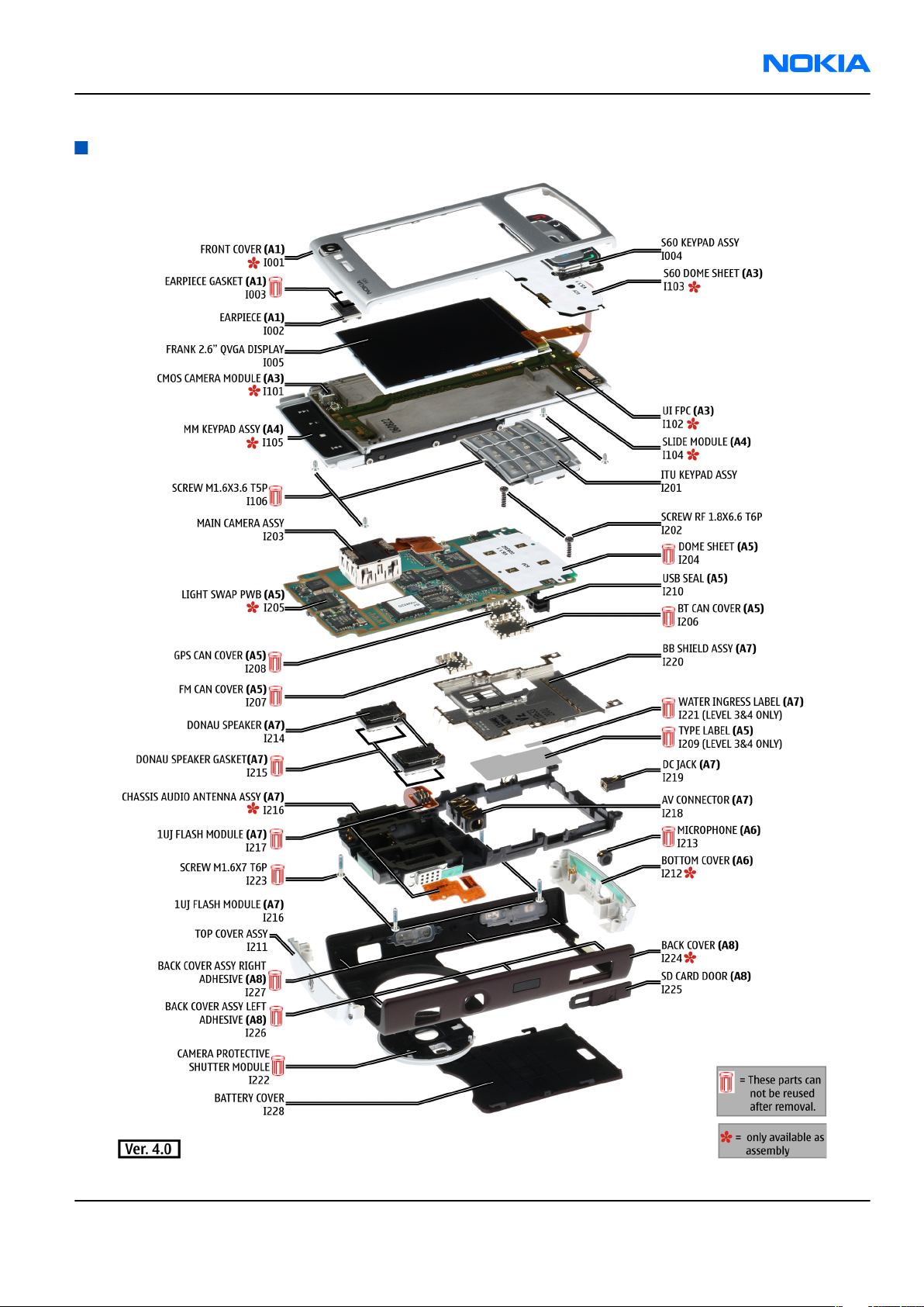
Exploded view
Issue 1 COMPANY CONFIDENTIAL Page 2 –5
Copyright © 2007 Nokia. All rights reserved.
Page 28
RM-159
Nokia Customer Care Parts Lists and Component Layouts
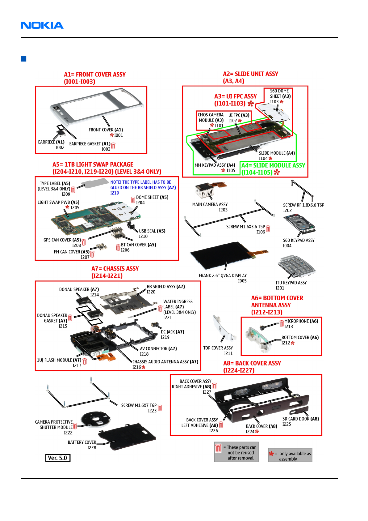
Spare parts overview
Page 2 –6 COMPANY CONFIDENTIAL Issue 1
Copyright © 2007 Nokia. All rights reserved.
Page 29
RM-159
Parts Lists and Component Layouts Nokia Customer Care
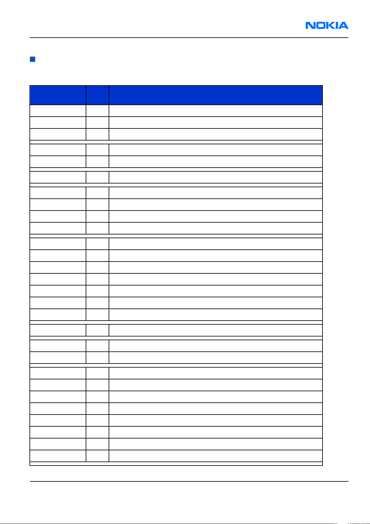
Mechanical spare parts list
Note: For Nokia product codes, please refer to the latest Service Bulletins on the Partner Website (PWS). To ensure you are always
using the latest codes, please check the PWS on a daily basis.
ITEM/CIRCUIT
REF.
QTY PART NAME
A1 1 FRONT COVER ASSY (I001 - I003)
I002 1 EARPIECE
I003 1 EARPIECE GASKET
I004 1 S60 KEYPAD ASSY
I005 1 FRANK 2.6” QVGA DISPLAY
A2 1 SLIDE UNIT ASSY (A3, A4)
I106 4 SCREW M1.6x3.6 T5P
I201 1 ITU KEYPAD ASSY
I202 2 SCREW RF 1.8x6.6 T6P
I203 1 MAIN CAMERA ASSY
A5 1 1TB LIGHT SWAP PACKAGE (I204 - I210)
I204 1 DOME SHEET
I206 1 BT CAN COVER
I207 1 FM CAN COVER
I208 1 GPS CAN COVER
I209 1 TYPE LABEL
I210 1 USB SEAL
I211 1 TOP COVER ASSY
A6 1 BOTTOM COVER ANTENNA ASSY (I212 - I213)
I213 1 MICROPHONE
A7 1 CHASSIS ASSY (I214 - I221)
I214 2 DONAU SPEAKER
I215 2 DONAU SPEAKER GASKET
I217 1 1UJ FLASH MODULE
I218 1 AV CONNECTOR
I219 1 DC JACK
I220 1 BB SHIELD ASSY
I221 1 WATER INGRESS LABEL
Issue 1 COMPANY CONFIDENTIAL Page 2 –7
Copyright © 2007 Nokia. All rights reserved.
Page 30
RM-159
Nokia Customer Care Parts Lists and Component Layouts
ITEM/CIRCUIT
REF.
I222 1 CAMERA PROTECTIVE SHUTTER MODULE
I223 4 SCREW M1.6x7 T6P
A8 1 BACK COVER ASSY (I224 - I227)
I225 1 SD CARD DOOR
I226 3 BACK COVER ASSY LEFT ADHESIVE
I227 3 BACK COVER ASSY RIGHT ADHESIVE
I228 1 BATTERY COVER
QTY PART NAME
Component parts lists and layouts
Component parts list 1TB_13
Item Side Grid ref. Type Description and value
SHIELD_040_0287
A6030 Bot E 4
15 BT CAN ASSY ~ ~
SHIELD_040_028725FM CAN ASSY
A6170 Bot C 9
SHIELD_040_028728GPS CAN ASSY
A6200 Bot H 3
B2200 Bot F 11 CRYSTAL_FC_135
C1100 Bot A 7 0402C_H0.6
C1101 Bot B 7 0402C_H0.6
C1102 Bot I 12 0402C
C1103 Bot I 13 0402C
C1104 Top J 5 0402C
C1105 Top J 5 0402C
C1150 Bot I 10 0603C
040-028725 ~ ~
040-028728 ~ ~
CRYSTAL 32.768KHZ
+-20PPM 12.5PF 32.768kHz ~
CHIPCAP X5R 100N K
16V 0402 100n 16V
CHIPCAP X5R 100N K
16V 0402 100n 16V
Chipcap X7R 10%
16V 0402 10n 16V
Chipcap X7R 10%
16V 0402 10n 16V
Chipcap X7R 10%
16V 0402 10n 16V
Chipcap X7R 10%
16V 0402 10n 16V
CHIPCAP X5R 1U K
16V 0603 1u0 16V
CHIPCAP X5R 1U K
C1151 Bot I 9 0603C
C1152 Bot I 10 0805C
Page 2 –8 COMPANY CONFIDENTIAL Issue 1
Copyright © 2007 Nokia. All rights reserved.
16V 0603 1u0 16V
CHIPCAP X5R 4U7 K
6V3 0805 4u7 6V3
Page 31

RM-159
Parts Lists and Component Layouts Nokia Customer Care
Item Side Grid ref. Type Description and value
CHIPCAP X5R 4U7 K
C1153 Bot I 10 0805C
C1155 Bot E 8 0603C
C1156 Bot E 7 TANT_TACR
C1157 Bot E 8 0402C Chipcap 5% NP0 22p 50V
C1400 Top D 11 0402C_H0.6
C1401 Top C 12 0402C
C1402 Top C 12 0402C
C1404 Bot I 12 0402C
6V3 0805 4u7 6V3
CHIPCAP X5R 4U7 K
6V3 0603 4u7 6.3V
CHIPTCAP 2U2 25V M
0805 2u2_25V 25V
CHIPCAP X5R 100N K
16V 0402 100n 16V
CHIPCAP X5R 1U5 K
4V 0402 1u5 4V
CHIPCAP X5R 1U5 K
4V 0402 1u5 4V
CHIPCAP X7R 10N K
25V 0402 10n 25V
CHIPCAP X5R 100N K
C1405 Bot H 13 0402C_H0.6
C1407 Bot G 13 0402C Chipcap 5% NP0 22p 50V
C1408 Bot I 12 0402C Chipcap 5% NP0 22p 50V
C2000 Bot C 3 0402C Chipcap 5% NP0 27p 50V
C2001 Bot C 3 0603C_H0.95
C2002 Bot B 11 0402C Chipcap 5% NP0 27p 50V
C2004 Bot C 10 0402C
C2005 Bot C 11 0603C
C2007 Bot B 10 0603C
C2008 Bot B 11 0402C Chipcap 5% NP0 18p 50V
C2009 Bot B 11 0402C Chipcap 5% NP0 18p 50V
C2010 Bot C 10 0402C
16V 0402 100n 16V
CHIPCAP X5R 470N K
25V 0603 470n 25V
CHIPCAP X5R 0U47 K
6.3V 0402 0u47 6V3
CHIPCAP X5R 2U2 K
6V3 0603 2u2 6V3
CHIPCAP X5R 2U2 K
6V3 0603 2u2 6V3
CHIPCAP X5R 0U47 K
6.3V 0402 0u47 6V3
CHIPCAP X5R 10U M
C2012 Bot C 11 0805C
C2013 Bot B 10 0402C
C2014 Bot C 11 0402C
Issue 1 COMPANY CONFIDENTIAL Page 2 –9
Copyright © 2007 Nokia. All rights reserved.
6V3 0805 10U 6V3
Chipcap X7R 10%
16V 0402 10n 16V
Chipcap X7R 10%
16V 0402 10n 16V
Page 32

RM-159
Nokia Customer Care Parts Lists and Component Layouts
Item Side Grid ref. Type Description and value
CHIPCAP X5R 1U K
C2018 Bot C 11 0402C
C2019 Bot C 11 0402C
C2030 Bot E 10 0402C Chipcap 5% NP0 22p 50V
C2033 Bot E 10 0402C Chipcap 5% NP0 22p 50V
6V3 0402 1u0 6.3V
CHIPCAP X5R 1U K
6V3 0402 1u0 6.3V
TANT_C_6.2X3.4_H
C2071 Bot E 17
C2072 Bot F 12 0402C Chipcap 5% NP0 33p 50V
C2073 Bot H 11 0402C Chipcap 5% NP0 33p 50V
C2106 Bot H 14 0402C
C2107 Bot H 14 0402C
C2108 Bot F 3 0402C
C2109 Bot F 3 0402C
C2110 Bot F 3 0402C
C2116 Bot B 14 0402C
C2117 Bot B 14 0402C
1.7
CHIPTCAP 150U M
10V 6X3.2X1.5 150u_10V 10V
Chipcap X7R 10%
50V 0402 1n0 50V
Chipcap X7R 10%
50V 0402 1n0 50V
Chipcap X7R 10%
50V 0402 1n0 50V
Chipcap X7R 10%
50V 0402 1n0 50V
Chipcap X7R 10%
50V 0402 1n0 50V
Chipcap X7R 10%
50V 0402 1n0 50V
Chipcap X7R 10%
50V 0402 1n0 50V
CHIPCAP X5R 4U7 K
C2120 Bot E 12 0603C
C2121 Bot E 12 0603C
C2122 Bot D 12 0402C
C2123 Bot D 11 0402C Chipcap 5% NP0 22p 50V
C2124 Bot D 11 0402C
C2125 Bot E 11 0402C Chipcap 5% NP0 22p 50V
C2126 Bot E 12 0402C_H0.6
C2127 Bot D 12 0402C
C2128 Bot E 11 0402C
Page 2 –10 COMPANY CONFIDENTIAL Issue 1
Copyright © 2007 Nokia. All rights reserved.
6V3 0603 4u7 6.3V
CHIPCAP X5R 1U K
16V 0603 1u0 16V
CERCAP X7R 22N K
16V 0402 22n 16V
CERCAP X7R 22N K
16V 0402 22n 16V
CHIPCAP X5R 100N K
16V 0402 100n 16V
CERCAP X7R 22N K
16V 0402 22n 16V
CERCAP X7R 22N K
16V 0402 22n 16V
Page 33

RM-159
Parts Lists and Component Layouts Nokia Customer Care
Item Side Grid ref. Type Description and value
CHIPCAP X5R 1U5 K
C2201 Bot F 10 0402C
C2202 Bot D 11 0603C
C2203 Bot D 11 0603C
C2205 Bot E 11 0402C
C2211 Bot E 9 0805C
C2213 Bot F 10 0405_DUAL
C2215 Bot G 10 0405_DUAL
4V 0402 1u5 4V
CHIPCAP X5R 2U2 K
6V3 0603 2u2 6V3
CHIPCAP X5R 2U2 K
6V3 0603 2u2 6V3
Chipcap X7R 10%
50V 0402 1n0 50V
CHIPCAP X5R 4U7 K
10V 0805 4u7 10V
CHIPCAP NETWORK
X5R 2X1U5 K 6V3
0405 2x1u5 6.3V
CHIPCAP NETWORK
X5R 2X1U5 K 6V3
0405 2x1u5 6.3V
C2216 Bot F 11 0402C
C2217 Bot E 10 0402C
C2220 Bot F 9 0405_DUAL
C2222 Bot E 9 0603C
C2225 Bot E 9 0603C
C2226 Bot F 11 0603C
C2227 Bot F 10 0405_DUAL
C2228 Bot F 10 0405_DUAL
CHIPCAP X5R 1U5 K
4V 0402 1u5 4V
CHIPCAP X5R 1U5 K
4V 0402 1u5 4V
CHIPCAP NETWORK
X5R 2X1U5 K 6V3
0405 2x1u5 6.3V
CHIPCAP X5R 1U K
6V3 0603 1u0 6.3V
CHIPCAP X5R 1U K
6V3 0603 1u0 6.3V
CHIPCAP X5R 1U K
6V3 0603 1u0 6.3V
CHIPCAP NETWORK
X5R 2X1U5 K 6V3
0405 2x1u5 6.3V
CHIPCAP NETWORK
X5R 2X1U5 K 6V3
0405 2x1u5 6.3V
CHIPCAP X5R 10U M
C2231 Bot D 9 0805C
C2232 Bot F 9 0405_DUAL
C2300 Bot E 6 0402C_H0.6
Issue 1 COMPANY CONFIDENTIAL Page 2 –11
Copyright © 2007 Nokia. All rights reserved.
6V3 0805 10U 6V3
CHIPCAP NETWORK
X5R 2X1U5 K 6V3
0405 2x1u5 6.3V
CHIPCAP X5R 100N K
16V 0402 100n 16V
Page 34

RM-159
Nokia Customer Care Parts Lists and Component Layouts
Item Side Grid ref. Type Description and value
CHIPCAP X5R 1U K
C2303 Bot F 7 0603C
C2304 Bot E 7 0402C
C2307 Bot F 6 0603C
C2312 Bot F 6 0405_DUAL
C2390 Bot F 12 0603C
C2391 Bot F 11 0603C
C2700 Bot H 10 0402C_H0.6
6V3 0603 1u0 6.3V
Chipcap X7R 10%
16V 0402 10n 16V
CHIPCAP X5R 1U K
6V3 0603 1u0 6.3V
CHIPCAP NETWORK
X5R 2X1U5 K 6V3
0405 2x1u5 6.3V
CHIPCAP X5R 4U7 K
6V3 0603 4u7 6.3V
CHIPCAP X5R 10UF
6V3 0603 10u 4V
CHIPCAP X5R 100N K
16V 0402 100n 16V
C2800 Top B 12 0402C_H0.6
C2801 Top C 12 0402C_H0.6
C2802 Bot C 14 0402C_H0.6
C2803 Top A 14 0402C_H0.6
C2804 Top C 12 0402C_H0.6
C2805 Top A 13 0402C_H0.6
C2806 Top B 15 0402C_H0.6
C2807 Top C 15 0603C
C2808 Top B 15 0402C_H0.6
C2809 Top B 15 0402C_H0.6
CHIPCAP X5R 100N K
16V 0402 100n 16V
CHIPCAP X5R 100N K
16V 0402 100n 16V
CHIPCAP X5R 100N K
16V 0402 100n 16V
CHIPCAP X5R 100N K
16V 0402 100n 16V
CHIPCAP X5R 100N K
16V 0402 100n 16V
CHIPCAP X5R 100N K
16V 0402 100n 16V
CHIPCAP X5R 100N K
16V 0402 100n 16V
CHIPCAP X5R 1U K
6V3 0603 1u0 6.3V
CHIPCAP X5R 100N K
16V 0402 100n 16V
CHIPCAP X5R 100N K
16V 0402 100n 16V
CHIPCAP X5R 100N K
C2810 Top D 12 0402C_H0.6
C2811 Top C 12 0402C_H0.6
C2812 Top C 15 0402C_H0.6
Page 2 –12 COMPANY CONFIDENTIAL Issue 1
Copyright © 2007 Nokia. All rights reserved.
16V 0402 100n 16V
CHIPCAP X5R 100N K
16V 0402 100n 16V
CHIPCAP X5R 100N K
16V 0402 100n 16V
Page 35

RM-159
Parts Lists and Component Layouts Nokia Customer Care
Item Side Grid ref. Type Description and value
CHIPCAP X5R 100N K
C2813 Top B 12 0402C_H0.6
C2814 Top B 12 0402C_H0.6
C2815 Top A 14 0402C_H0.6
C2816 Bot C 14 0402C_H0.6
C2817 Top A 15 0402C_H0.6
C2818 Top B 15 0402C_H0.6
C2819 Top A 14 0603C
C2820 Top A 13 0402C Chipcap 5% NP0 27p 50V
16V 0402 100n 16V
CHIPCAP X5R 100N K
16V 0402 100n 16V
CHIPCAP X5R 100N K
16V 0402 100n 16V
CHIPCAP X5R 100N K
16V 0402 100n 16V
CHIPCAP X5R 100N K
16V 0402 100n 16V
CHIPCAP X5R 100N K
16V 0402 100n 16V
CHIPCAP X5R 1U K
6V3 0603 1u0 6.3V
C2821 Top C 12 0402C Chipcap 5% NP0 27p 50V
CHIPCAP X5R 100N K
C3000 Top C 11 0402C_H0.6
C3001 Top A 10 0402C_H0.6
C3002 Top C 11 0402C_H0.6
C3003 Top A 11 0402C
C3004 Top B 12 0402C_H0.6
C3005 Top C 11 0402C_H0.6
C3006 Top C 11 0402C_H0.6
C3007 Top A 12 0402C
C3008 Top A 11 0402C_H0.6
16V 0402 100n 16V
CHIPCAP X5R 100N K
16V 0402 100n 16V
CHIPCAP X5R 100N K
16V 0402 100n 16V
Chipcap X7R 10%
16V 0402 10n 16V
CHIPCAP X5R 100N K
16V 0402 100n 16V
CHIPCAP X5R 100N K
16V 0402 100n 16V
CHIPCAP X5R 100N K
16V 0402 100n 16V
Chipcap X7R 10%
16V 0402 10n 16V
CHIPCAP X5R 100N K
16V 0402 100n 16V
CHIPCAP NETWORK
X5R 2X1U5 K 6V3
C4200 Bot C 6 0405_DUAL
C4201 Bot D 7 0805C
C4202 Bot D 6 0805C
Issue 1 COMPANY CONFIDENTIAL Page 2 –13
Copyright © 2007 Nokia. All rights reserved.
0405 2x1u5 6.3V
CHIPCAP X5R 22U M
6V3 0805 22u 6V3
CHIPCAP X5R 22U M
6V3 0805 22u 6V3
Page 36

RM-159
Nokia Customer Care Parts Lists and Component Layouts
Item Side Grid ref. Type Description and value
CHIPCAP X5R 1U5 K
C4203 Bot C 8 0402C
C4204 Bot B 7 0402C_H0.6
C4205 Bot C 8 0805C
C4206 Bot D 6 0805C
C4207 Top B 7 0402C_H0.6
C4208 Bot C 8 0405_DUAL
C4209 Bot B 7 0805C
4V 0402 1u5 4V
CHIPCAP X5R 100N K
16V 0402 100n 16V
CHIPCAP X5R 22U M
6V3 0805 22u 6V3
CHIPCAP X5R 22U M
6V3 0805 22u 6V3
CHIPCAP X5R 100N K
16V 0402 100n 16V
CHIPCAP NETWORK
X5R 2X1U5 K 6V3
0405 2x1u5 6.3V
CHIPCAP X5R 22U M
6V3 0805 22u 6V3
C4211 Bot B 6 0402C
C4212 Bot C 8 0402C
C4213 Bot D 7 0402C_H0.6
C4214 Bot D 7 0402C
C4215 Bot D 7 0405_DUAL
C4216 Bot D 8 0805C
C4219 Top B 7 0402C_H0.6
C4221 Bot C 8 0402C
C4402 Top I 10 0402C
CHIPCAP X5R 1U5 K
4V 0402 1u5 4V
CHIPCAP X5R 1U5 K
4V 0402 1u5 4V
CHIPCAP X5R 100N K
16V 0402 100n 16V
CHIPCAP X5R 1U5 K
4V 0402 1u5 4V
CHIPCAP NETWORK
X5R 2X1U5 K 6V3
0405 2x1u5 6.3V
CHIPCAP X5R 22U M
6V3 0805 22u 6V3
CHIPCAP X5R 100N K
16V 0402 100n 16V
CHIPCAP X5R 1U5 K
4V 0402 1u5 4V
Chipcap X7R 10%
50V 0402 1n0 50V
Chipcap X7R 10%
C4403 Top I 10 0402C
C4404 Bot H 9 0402C Chipcap 5% NP0 22p 50V
C4405 Top H 10 0402C Chipcap 5% NP0 22p 50V
C4406 Bot H 9 0402C Chipcap 5% NP0 22p 50V
C4408 Bot H 9 0402C Chipcap 5% NP0 22p 50V
Page 2 –14 COMPANY CONFIDENTIAL Issue 1
Copyright © 2007 Nokia. All rights reserved.
50V 0402 1n0 50V
Page 37

RM-159
Parts Lists and Component Layouts Nokia Customer Care
Item Side Grid ref. Type Description and value
CHIPCAP X5R 100N K
C4600 Top A 10 0402C_H0.6
C4601 Top A 9 0402C
C4602 Top A 9 0402C Chipcap 5% NP0 22p 50V
C4800 Top E 8 0402C_H0.6
C4801 Top C 7 0402C_H0.6
C4802 Top B 9 0402C_H0.6
C4803 Top B 8 0402C_H0.6
C4804 Top E 8 0402C_H0.6
16V 0402 100n 16V
CHIPCAP X5R 1U K
6V3 0402 1u0 6.3V
CHIPCAP X5R 100N K
16V 0402 100n 16V
CHIPCAP X5R 100N K
16V 0402 100n 16V
CHIPCAP X5R 100N K
16V 0402 100n 16V
CHIPCAP X5R 100N K
16V 0402 100n 16V
CHIPCAP X5R 100N K
16V 0402 100n 16V
C4806 Top E 9 0402C_H0.6
C4807 Top D 10 0402C_H0.6
C4808 Top D 10 0402C_H0.6
C4810 Top E 10 0402C_H0.6
C4814 Top D 10 0402C
C4816 Top D 10 0402C_H0.6
C4817 Top D 10 0402C_H0.6
C4818 Top C 10 0402C_H0.6
C4819 Top B 9 0402C_H0.6
C4820 Top E 7 0402C_H0.6
CHIPCAP X5R 100N K
16V 0402 100n 16V
CHIPCAP X5R 100N K
16V 0402 100n 16V
CHIPCAP X5R 100N K
16V 0402 100n 16V
CHIPCAP X5R 100N K
16V 0402 100n 16V
CHIPCAP X5R 1U5 K
4V 0402 1u5 4V
CHIPCAP X5R 100N K
16V 0402 100n 16V
CHIPCAP X5R 100N K
16V 0402 100n 16V
CHIPCAP X5R 100N K
16V 0402 100n 16V
CHIPCAP X5R 100N K
16V 0402 100n 16V
CHIPCAP X5R 100N K
16V 0402 100n 16V
CHIPCAP X5R 100N K
C4821 Top D 7 0402C_H0.6
C4822 Top B 7 0402C_H0.6
C4823 Top B 8 0402C_H0.6
Issue 1 COMPANY CONFIDENTIAL Page 2 –15
Copyright © 2007 Nokia. All rights reserved.
16V 0402 100n 16V
CHIPCAP X5R 100N K
16V 0402 100n 16V
CHIPCAP X5R 100N K
16V 0402 100n 16V
Page 38

RM-159
Nokia Customer Care Parts Lists and Component Layouts
Item Side Grid ref. Type Description and value
CHIPCAP X5R 100N K
C4824 Top E 8 0402C_H0.6
C4825 Top E 7 0402C
C4826 Top E 7 0402C
C4827 Top F 8 0402C
C4828 Top E 7 0402C Chipcap 5% NP0 22p 50V
C4830 Top D 7 0402C_H0.6
C4832 Top B 7 0402C_H0.6
C4833 Top B 8 0402C_H0.6
16V 0402 100n 16V
CHIPCAP X5R 1U5 K
4V 0402 1u5 4V
CHIPCAP X5R 1U5 K
4V 0402 1u5 4V
Chipcap X7R 10%
50V 0402 1n0 50V
CHIPCAP X5R 100N K
16V 0402 100n 16V
CHIPCAP X5R 100N K
16V 0402 100n 16V
CHIPCAP X5R 100N K
16V 0402 100n 16V
C4834 Top E 9 0402C_H0.6
C4835 Top E 8 0402C
C4836 Top E 7 0402C_H0.6
C5200 Bot B 6 0402C_H0.6
C5201 Bot B 6 0402C
C5390 Top C 7 0402C_H0.6
C5400 Top E 11 0402C_H0.6
C5402 Top E 10 0402C_H0.6
C5410 Top G 13 0402C_H0.6
C5411 Top G 13 0402C_H0.6
CHIPCAP X5R 100N K
16V 0402 100n 16V
CHIPCAP X5R 1U5 K
4V 0402 1u5 4V
CHIPCAP X5R 100N K
16V 0402 100n 16V
CHIPCAP X5R 100N K
16V 0402 100n 16V
CHIPCAP X5R 1U5 K
4V 0402 1u5 4V
CHIPCAP X5R 100N K
16V 0402 100n 16V
CHIPCAP X5R 100N K
16V 0402 100n 16V
CHIPCAP X5R 100N K
16V 0402 100n 16V
CHIPCAP X5R 100N K
16V 0402 100n 16V
CHIPCAP X5R 100N K
16V 0402 100n 16V
CHIPCAP X5R 100N K
C5412 Top F 13 0402C_H0.6
C5413 Top F 13 0402C_H0.6
C5414 Top E 11 0402C_H0.6
Page 2 –16 COMPANY CONFIDENTIAL Issue 1
Copyright © 2007 Nokia. All rights reserved.
16V 0402 100n 16V
CHIPCAP X5R 100N K
16V 0402 100n 16V
CHIPCAP X5R 100N K
16V 0402 100n 16V
Page 39

RM-159
Parts Lists and Component Layouts Nokia Customer Care
Item Side Grid ref. Type Description and value
CHIPCAP X5R 100N K
C5415 Top G 11 0402C_H0.6
C5416 Top E 12 0402C_H0.6
C5417 Top E 11 0402C
C5418 Top E 11 0402C_H0.6
C5419 Top F 11 0402C_H0.6
C5420 Top G 11 0402C
C5421 Top F 11 0402C_H0.6
C5450 Top E 13 0603C
16V 0402 100n 16V
CHIPCAP X5R 100N K
16V 0402 100n 16V
CHIPCAP X5R 1U5 K
4V 0402 1u5 4V
CHIPCAP X5R 100N K
16V 0402 100n 16V
CHIPCAP X5R 100N K
16V 0402 100n 16V
CHIPCAP X5R 1U5 K
4V 0402 1u5 4V
CHIPCAP X5R 100N K
16V 0402 100n 16V
CHIPCAP X5R 10UF
6V3 0603 10u 4V
C5451 Top D 12 0402C_H0.6
C5452 Top D 12 0402C_H0.6
C5453 Top A 10 0805C
C5454 Top D 10 0603C_H0.95
C5455 Top D 10 0603C_H0.95
C5456 Top C 10 0603C_H0.95
C5457 Top C 10 0603C_H0.95
C5461 Top C 10 0402C_H0.6
C5463 Top E 12 0402C
C5464 Top D 11 0805C_H0.95
CHIPCAP X5R 100N K
16V 0402 100n 16V
CHIPCAP X5R 100N K
16V 0402 100n 16V
CHIPCAP X5R 4U7 K
6V3 0805 4u7 6V3
CHIPCAP X5R 1U K
25V 0603 1u0 25V
CHIPCAP X5R 1U K
25V 0603 1u0 25V
CHIPCAP X5R 1U K
25V 0603 1u0 25V
CHIPCAP X5R 1U K
25V 0603 1u0 25V
CHIPCAP X5R 100N K
16V 0402 100n 16V
CHIPCAP X5R 1U5 K
4V 0402 1u5 4V
CHIPCAP X5R 10U M
6V3 T=0.95mm
0805 10u 6V3
CHIPCAP X5R 100N K
C5500 Top B 7 0402C_H0.6
C5650 Top A 7 0402C_H0.6
Issue 1 COMPANY CONFIDENTIAL Page 2 –17
Copyright © 2007 Nokia. All rights reserved.
16V 0402 100n 16V
CHIPCAP X5R 100N K
16V 0402 100n 16V
Page 40

RM-159
Nokia Customer Care Parts Lists and Component Layouts
Item Side Grid ref. Type Description and value
C6031 Bot F 5 0402C Chipcap 5% NP0 18p 50V
C6032 Bot E 3 0402C Chipcap 5% NP0 100p 50V
Chipcap X7R 10%
C6033 Bot E 4 0402C
C6034 Bot E 4 0402C
C6035 Bot F 4 0402C
C6036 Bot E 3 0402C
C6037 Bot F 3 0402C
C6038 Bot F 4 0402C
16V 0402 10n 16V
Chipcap X7R 10%
16V 0402 10n 16V
Chipcap X7R 10%
16V 0402 10n 16V
Chipcap X7R 10%
16V 0402 10n 16V
CHIPCAP X5R 1U5 K
4V 0402 1u5 4V
Chipcap X7R 10%
16V 0402 10n 16V
C6039 Bot E 4 0402C Chipcap 5% NP0 18p 50V
Chipcap +-0.25pF
C6051 Bot F 4 0402C
C6052 Bot E 4 0402C
C6055 Bot F 5 0402C
C6157 Bot B 9 0402C
C6158 Bot B 9 0402C_H0.6
C6159 Bot C 9 0402C
C6161 Bot C 9 0402C_H0.6
C6162 Bot B 9 0402C
C6163 Bot B 10 0402C
NP0 2p7 50V
Chipcap +-0.25pF
NP0 2p7 50V
CHIPCAP X5R 1U K
6V3 0402 1u0 6.3V
Chipcap X7R 10%
16V 0402 10n 16V
CHIPCAP X5R 100N K
16V 0402 100n 16V
CHIPCAP X7R 33N K
10V 0402 33n 10V
CHIPCAP X5R 100N K
16V 0402 100n 16V
CHIPCAP X7R 33N K
10V 0402 33n 10V
CHIPCAP X7R 33N K
10V 0402 33n 10V
CHIPCAP X5R 100N K
C6164 Bot C 10 0402C_H0.6
C6165 Bot C 9 0402C
C6170 Bot B 10 0402C
C6174 Bot C 9 0402C_H0.6
Page 2 –18 COMPANY CONFIDENTIAL Issue 1
Copyright © 2007 Nokia. All rights reserved.
16V 0402 100n 16V
CHIPCAP X7R 33N K
10V 0402 33n 10V
Chipcap X7R 10%
16V 0402 10n 16V
CHIPCAP X5R 100N K
16V 0402 100n 16V
Page 41

RM-159
Parts Lists and Component Layouts Nokia Customer Care
Item Side Grid ref. Type Description and value
C6176 Bot C 10 0402C Chipcap 5% NP0 100p 50V
C6178 Bot C 10 0402C Chipcap 5% NP0 27p 50V
C6179 Bot B 10 0402C Chipcap 5% NP0 47p 50V
Chipcap X5R 10%
C6180 Bot C 9 0402C
C6182 Bot C 9 0402C
C6184 Bot C 9 0402C
C6185 Bot C 9 0402C
C6200 Bot G 3 0402C Chipcap 5% NP0 33p 50V
C6201 Bot H 3 0402C Chipcap 5% NP0 33p 50V
C6202 Bot H 3 0402C_H0.6
6.3V 0402 220n 6.3V
Chipcap X5R 10%
6.3V 0402 220n 6.3V
Chipcap X5R 10%
6.3V 0402 220n 6.3V
Chipcap X5R 10%
6.3V 0402 220n 6.3V
CHIPCAP X5R 100N K
16V 0402 100n 16V
C6203 Bot H 4 0402C_H0.6
C6204 Bot H 3 0402C_H0.6
C6205 Bot G 3 0402C_H0.6
C6206 Bot H 4 0402C_H0.6
C6207 Bot H 3 0402C_H0.6
C6209 Bot H 4 0402C_H0.6
C6210 Bot H 4 0402C_H0.6
C6211 Bot G 3 0402C
C6212 Bot H 4 0402C_H0.6
C6300 Top H 8 0805C
CHIPCAP X5R 100N K
16V 0402 100n 16V
CHIPCAP X5R 100N K
16V 0402 100n 16V
CHIPCAP X5R 100N K
16V 0402 100n 16V
CHIPCAP X5R 100N K
16V 0402 100n 16V
CHIPCAP X5R 100N K
16V 0402 100n 16V
CHIPCAP X5R 100N K
16V 0402 100n 16V
CHIPCAP X5R 100N K
16V 0402 100n 16V
Chipcap +-0.25pF
NP0 3p3 50V
CHIPCAP X5R 100N K
16V 0402 100n 16V
CHIPCAP X5R 22U M
6V3 0805 22u 6V3
CHIPCAP X5R 1U5 K
C6301 Top G 8 0402C
C6302 Top G 8 0402C
Issue 1 COMPANY CONFIDENTIAL Page 2 –19
Copyright © 2007 Nokia. All rights reserved.
4V 0402 1u5 4V
CHIPCAP X5R 1U5 K
4V 0402 1u5 4V
Page 42

RM-159
Nokia Customer Care Parts Lists and Component Layouts
Item Side Grid ref. Type Description and value
CHIPCAP X5R 2U2 K
C6303 Top H 8 0603C
C6304 Top I 8 0402C_H0.6
C6305 Bot F 7 0402C_H0.6
C6306 Top G 8 0402C_H0.6
C6307 Top G 6 0402C
C6308 Top H 7 0402C
C6309 Top G 8 0402C_H0.6
C6329 Top I 8 0402C Chipcap 5% NP0 10p 50V
6V3 0603 2u2 6V3
CHIPCAP X5R 100N K
16V 0402 100n 16V
CHIPCAP X5R 100N K
16V 0402 100n 16V
CHIPCAP X5R 100N K
16V 0402 100n 16V
CHIPCAP X5R 1U K
6V3 0402 1u0 6.3V
Chipcap +-0.25pF
NP0 6p8 50V
CHIPCAP X5R 100N K
16V 0402 100n 16V
CHIPCAP X5R 2U2 K
C6330 Top I 8 0603C
C6335 Top I 8 0402C
C6338 Top I 8 0402C Chipcap 5% NP0 47p 50V
C6396 Top H 7 0402C
C6397 Top H 7 0402C
C6398 Top H 7 0402C
C6399 Top H 7 0402C
C6450 Bot E 4 0402C
C6458 Bot D 4 0402C
C6459 Bot E 4 0402C
6V3 0603 2u2 6V3
CHIPCAP NP0 220P J
25V 0402 220p 25V
Chipcap +-0.25pF
NP0 6p8 50V
Chipcap +-0.25pF
NP0 6p8 50V
Chipcap +-0.25pF
NP0 6p8 50V
Chipcap +-0.25pF
NP0 6p8 50V
Chipcap +-0.25pF
NP0 6p8 50V
CHIPCAP X5R 1U5 K
4V 0402 1u5 4V
CHIPCAP X5R 1U K
6V3 0402 1u0 6.3V
CHIPCAP X5R 10UF
C7500 Top B 18 0603C
C7507 Top C 18 0402C
C7513 Top B 18 0402C
Page 2 –20 COMPANY CONFIDENTIAL Issue 1
Copyright © 2007 Nokia. All rights reserved.
6V3 0603 10u 4V
Chipcap X7R 10%
16V 0402 10n 16V
Chipcap X7R 10%
25V 0402 4n7 25V
Page 43

RM-159
Parts Lists and Component Layouts Nokia Customer Care
Item Side Grid ref. Type Description and value
CHIPCAP X5R 100N K
C7518 Top C 19 0402C_H0.6
C7519 Top B 19 0402C
C7520 Top B 19 0402C Chipcap 5% X7R 1n0 50V
C7521 Top F 19 0402C
C7523 Top F 17 0402C
C7524 Top E 19 0402C Chipcap 5% NP0 22p 50V
C7525 Top E 19 0402C Chipcap 5% NP0 10p 50V
C7543 Top H 18 0603C
C7544 Top H 18 0402C
16V 0402 100n 16V
CHIPCAP X5R 1U5 K
4V 0402 1u5 4V
Chipcap +-0.25pF
NP0 3p3 50V
Chipcap +-0.25pF
NP0 3p3 50V
CHIPCAP X5R 4U7 K
6V3 0603 4u7 6.3V
CERCAP X7R 22N K
16V 0402 22n 16V
C7545 Top H 18 0402C Chipcap 5% NP0 10p 50V
CHIPCAP X5R 10UF
C7547 Top H 19 0603C
C7548 Top I 18 0402C
C7549 Top G 18 0402C
C7550 Top I 18 0402C Chipcap 5% X7R 1n0 50V
C7553 Top G 18 0402C Chipcap 5% X7R 1n0 50V
C7580 Top B 19 0402C_H0.6
C7581 Top B 19 0402C_H0.6
C7582 Top B 19 0402C_H0.6
C7583 Top B 19 0402C_H0.6
C7586 Top D 19 0402C Chipcap 5% NP0 10p 50V
6V3 0603 10u 4V
Chipcap X7R 10%
16V 0402 8n2 16V
Chipcap X7R 10%
16V 0402 8n2 16V
CHIPCAP X5R 100N K
16V 0402 100n 16V
CHIPCAP X5R 100N K
16V 0402 100n 16V
CHIPCAP X5R 100N K
16V 0402 100n 16V
CHIPCAP X5R 100N K
16V 0402 100n 16V
C7587 Top D 19 0402C Chipcap 5% NP0 10p 50V
CHIPCAP X5R 10UF
C7590 Top D 17 0603C
C7591 Top D 18 0603C
D2800 Top B 14 PBGA_N385
Issue 1 COMPANY CONFIDENTIAL Page 2 –21
Copyright © 2007 Nokia. All rights reserved.
6V3 0603 10u 4V
CHIPCAP X5R 10UF
6V3 0603 10u 4V
RAPIDOYAWE V1.11
PA 385ZWK 12X12 ~ ~
Page 44

RM-159
Nokia Customer Care Parts Lists and Component Layouts
Item Side Grid ref. Type Description and value
COMBO 128M NOR +
D3000 Top B 11 FBGA133_8.1X8.1
D4800 Top D 8 PBGA447
FBGA152_EMPTY_H
D5000 Top D 8
D5390 Top C 7
D5410 Top F 12 FBGA_195
2.0
XBGA_N6_1.45X0.9
5_H0.625
128M DDR DRAM
FBGA133
MCU OMAP2420POP
PS2.2 N1 PBGA447 ~ ~
COMBO 512MB DDR +
2G M3 FBGA152
PBFREE
IC 2XBUFFER
74LVC2G34YZTR
WCSP6 ~ ~
OMAP DM290
GOLDENEYE NFBGA ~ ~
128MNOR
+128MDDR ~
32Mx16/12
8Mx16 ~
WBGA_60_8.1X6.6_
D5411 Top F 10
D5500 Top B 7
D6450 Bot D 4 XBGA_N5_H0.625
E2001 Bot A 13 SPACER_411CSC SPACER METAL ~ ~
E2002 Bot C 13 SPACER_411CSC SPACER METAL ~ ~
E2003 Bot B 12 SPACER_411CSC SPACER METAL ~ ~
E2004 Bot C 12 SPACER_411CSC SPACER METAL ~ ~
E2005 Bot B 13 SPACER_411CSC SPACER METAL ~ ~
E2006 Bot B 13 SPACER_411CSC SPACER METAL ~ ~
F2000 Bot B 3
G2200 Bot D 9 BATTER_EECEP
H0.9
XBGA_N6_1.45X0.9
5_H0.625
0402_FUSE_AVX_H
0.5
SDRAM 8MX16 1.8V/
1.8V FBGA60 PBFREE 8Mx16 ~
IC 2XBUFFER
74LVC2G34YZTR
WCSP6 ~ ~
OR-GATE 2INPUT
74LVC1G32YZTR
WCSP-5 ~ ~
SM FUSE FF 2A 32V
0402 2.0A ~
RTC BACUP CAPAC
311 SIZE FOR 2.6V
4UAH 2.6V ~
TCXO 16.368MHZ
1.5PPM 2.6V 1.4MA
G6200 Bot G 3 TCO_5879
VCTCXO_3.4X2.7_4
G6450 Bot E 5
G7501 Top B 17 NKG3176B_H1.0
L1150 Bot E 8
Page 2 –22 COMPANY CONFIDENTIAL Issue 1
P2_H1.0
CHOKE_SER300_H1.5CHOKE 22U M 0R7
Copyright © 2007 Nokia. All rights reserved.
3225 16.368MHz ~
TCXO 38.4MHZ
+-10PPM 2.78V 38.4MHz ~
VCTCXO 38.4MHZ
2.5V 2MA 38.4MHz ~
0.35A 3.0x3.0x1.5 22uH ~
Page 45

RM-159
Parts Lists and Component Layouts Nokia Customer Care
Item Side Grid ref. Type Description and value
L1404 Bot I 12 FERRITE_0402
L1405 Bot H 13 FERRITE_0402
L1406 Bot H 12 FERRITE_0402
L1407 Bot H 13 FERRITE_0402
L1408 Bot H 12 FERRITE_0402
L2000 Bot B 3 0603_BLM
L2001 Bot B 11 0603_BLM
L2002 Bot B 11 0405_2_DLM11G
L2003 Bot A 11 0402L_XL
L2101 Bot E 12 0603_BLM
FERRITE BEAD 600R
300MA 0.6R 0402
FERRITE BEAD 600R
300MA 0.6R 0402
FERRITE BEAD 600R
300MA 0.6R 0402
FERRITE BEAD 600R
300MA 0.6R 0402
FERRITE BEAD 600R
300MA 0.6R 0402
FERR.BEAD 220R/
100M 2A 0R05 0603
FERR.BEAD 220R/
100M 2A 0R05 0603
CHIP BEAD ARRAY
2X600R 0405
CHIP COIL 68N J
Q17/300M 0402 68nH ~
FERR.BEAD 220R/
100M 2A 0R05 0603
600R/
300mA ~
600R/
300mA ~
600R/
300mA ~
600R/
300mA ~
600R/
300mA ~
220R/
100MHz ~
220R/
100MHz ~
2x600R/
100MHz ~
220R/
100MHz ~
L2102 Bot I 14 0603L
L2103 Bot H 14 0603L
L2104 Bot E 12 0603_BLM
L2105 Bot F 3 0402L
L2106 Bot F 3 0402L
L2111 Bot D 12 0603_BLM
L2112 Bot C 14 COIL_0603CS
CHIP COIL WW 4N7
+-0.5NH
Q35/6000MHZ
850MA 0603 4n7H ~
CHIP COIL WW 4N7
+-0.5NH
Q35/6000MHZ
850MA 0603 4n7H ~
FERR.BEAD 220R/
100M 2A 0R05 0603
FERR.BEAD
240R7100M 0.4A
0R4 0402
FERR.BEAD
240R7100M 0.4A
0R4 0402
FERR.BEAD 220R/
100M 2A 0R05 0603
CHIP COIL 56N J
Q38/250MHZ 0603 56nH ~
220R/
100MHz ~
240R/
100MHz ~
240R/
100MHz ~
220R/
100MHz ~
CHIP COIL 56N J
L2113 Bot B 14 COIL_0603CS
Issue 1 COMPANY CONFIDENTIAL Page 2 –23
Copyright © 2007 Nokia. All rights reserved.
Q38/250MHZ 0603 56nH ~
Page 46

RM-159
Nokia Customer Care Parts Lists and Component Layouts
Item Side Grid ref. Type Description and value
L2114 Bot D 12 0603_BLM
L2120 Bot E 12 0603_BLM
L2202 Bot F 9 0603_BLM
L2205 Bot D 10 0603_BLM
L2390 Bot F 12 CHOKE_SER300
L2391 Bot F 12 0603_BLM
L4200 Bot B 7 0603_BLM
L4201 Bot D 7 0603_BLM
L4202 Bot D 6 0603_BLM
L4203 Bot B 8 CHOKE_SER400
FERR.BEAD 220R/
100M 2A 0R05 0603
FERR.BEAD 220R/
100M 2A 0R05 0603
FERR.BEAD 220R/
100M 2A 0R05 0603
FERR.BEAD 220R/
100M 2A 0R05 0603
CHOKE 1U 0R1 1.5A
3.0X3.0X1.0 1uH ~
FERR.BEAD 220R/
100M 2A 0R05 0603
FERR.BEAD 220R/
100M 2A 0R05 0603
FERR.BEAD 220R/
100M 2A 0R05 0603
FERR.BEAD 220R/
100M 2A 0R05 0603
INDUCT WW 4.7UH M
1.15A 0R12 4X4X1.8 4u7H ~
220R/
100MHz ~
220R/
100MHz ~
220R/
100MHz ~
220R/
100MHz ~
220R/
100MHz ~
220R/
100MHz ~
220R/
100MHz ~
220R/
100MHz ~
CHOKE_SER300_H1.5CHOKE 4U7 0.86A
L4204 Bot C 6
CHOKE_SER300_H1.5CHOKE 4U7 0.86A
L4205 Bot D 7
L4400 Bot I 10 0405_2_H1.0
L4401 Top I 10 0402L
L4402 Top I 10 0402L
L4800 Top D 10 FERRITE_0402
L5200 Bot B 6 FERRITE_0402
L5410 Top F 13 FERRITE_0402
L5450 Top B 10 CHOKE_SER300
0R2 3X3X1.5 4u7H ~
0R2 3X3X1.5 4u7H ~
CHIP BEAD ARRAY
2X1000R 0405
FERR.BEAD
240R7100M 0.4A
0R4 0402
FERR.BEAD
240R7100M 0.4A
0R4 0402
FERRITE BEAD 600R
300MA 0.6R 0402
FERRITE BEAD 600R
300MA 0.6R 0402
FERRITE BEAD 600R
300MA 0.6R 0402
CHOKE 3.3UH 0R252
0A82 310 CASE SIZE 3u3H ~
2x1000R/
100MHz ~
240R/
100MHz ~
240R/
100MHz ~
600R/
300mA ~
600R/
300mA ~
600R/
300mA ~
CHIP COIL 2N7+-0N3
L6030 Bot E 4 0402L
Page 2 –24 COMPANY CONFIDENTIAL Issue 1
Copyright © 2007 Nokia. All rights reserved.
Q29/800M 0402 2n7H ~
Page 47

RM-159
Parts Lists and Component Layouts Nokia Customer Care
Item Side Grid ref. Type Description and value
CHIP COIL 2N7+-0N3
L6031 Bot F 4 0402L
L6032 Bot F 4 0402L
L6156 Bot B 9 COIL_0603CS
L6176 Bot C 10 COIL_LQW1608
L6200 Bot H 3 0402L
L6201 Bot H 4 0402L
L7405 Bot G 18 0402L
L7500 Top C 19 0402L
Q29/800M 0402 2n7H ~
CHIP COIL 22N J
Q28/800M 0402 22nH ~
CHIP COIL 47N G
Q38/200MHZ 0603 47nH ~
CHIP COIL 120N J
Q32/150MHZ 0603 120nH ~
CHIP COIL 3N9 +-0N3
Q28/800M 0402 3n9H ~
CHIP COIL 6N8 J
Q27/800M 0402 6n8H ~
CHIP COIL 33N J
Q23/800M 0402 33nH ~
CHIP COIL 12N J
Q31/800M 0402 12nH ~
L7501 Top D 18 0402L
L7502 Top C 17 0603_BLM
L7503 Top C 19 0402L
L7506 Top C 17 0402L
L7510 Top F 17 FERRITE_FBMJ1608
L7526 Top D 19 0402L
CHOKE_SER300_H1.5CHOKE 3U3 1.2A
L7540 Top G 19
L7550 Top I 19 0402L
CHIP COIL 12N J
Q31/800M 0402 12nH ~
FERR.BEAD 220R/
100M 2A 0R05 0603
FERR.BEAD
240R7100M 0.4A
0R4 0402
FERR.BEAD
240R7100M 0.4A
0R4 0402
FERRITE BEAD 0R01
28R/100MHZ 0603
FERR.BEAD
240R7100M 0.4A
0R4 0402
0R096 3X3X1.5 3u3H ~
FERR.BEAD
240R7100M 0.4A
0R4 0402
220R/
100MHz ~
240R/
100MHz ~
240R/
100MHz ~
28R/
100MHz ~
240R/
100MHz ~
240R/
100MHz ~
CHIP COIL 12N J
L7588 Top C 18 0402L
L7589 Top C 17 0402L
INDUCTOR_MDT2520INDUCT ML CHIP PWR
L7590 Top D 17
Issue 1 COMPANY CONFIDENTIAL Page 2 –25
Copyright © 2007 Nokia. All rights reserved.
Q31/800M 0402 12nH ~
CHIP COIL 6N8 J
Q27/800M 0402 6n8H ~
3U3 M 0R15 0.2A 3u3H ~
Page 48

RM-159
Nokia Customer Care Parts Lists and Component Layouts
Item Side Grid ref. Type Description and value
L7591 Top H 19 FERRITE_FBMJ1608
L7592 Top D 18 FERRITE_FBMJ1608
VIBRA_M_KHN4NX
M2100 Bot G 2
N1100 Bot A 6 LFCSP14
N1101 Bot I 13 SH248CSP
N1102 Top I 5 SH248CSP
N1150 Bot I 9
N1151 Bot F 8 USMD8_1.69X1.69
N2000 Bot C 10
1RA
USMD_18_2.433X2.
128
XBGA_N16_2.19X2.
19
FERRITE BEAD 0R01
28R/100MHZ 0603
FERRITE BEAD 0R01
28R/100MHZ 0603
SMD VIBRA MOTOR
1.3V 80MA 9000RPM ~ ~
ACCELEROMETER 3-
AXIS 2.5V LGA14 ~ ~
HALL IC SWITCH
SH248CSP VCC ~ ~
HALL IC SWITCH
SH248CSP VCC ~ ~
DRIVER LED WHITE
LM2796TLX USMD18 ~ ~
WHITE LED DRIVER
4LEDS 500MW
8BUMP USMD8 ~ ~
AFAMP TPA4411 2X
80MW 1.8/4.5V
WCSP16 ~ ~
28R/
100MHz ~
28R/
100MHz ~
CSP_8_2.118X1.11
N2001 Bot C 11
N2002 Bot C 11
N2030 Bot D 10
N2031 Bot D 10
N2120 Bot E 12 XBGA_N16
N2200 Bot F 10 TFBGA_105
N2300 Bot F 6 TFBGA64_H1.2
N2390 Bot F 12
8
CSP_8_2.118X1.11
8
CSP_8_2.118X1.11
8
CSP_8_2.118X1.11
8
USMD_12_2.382X1.
722
IC ANALOG SWITCH
SPDT LOW
THRESHOLD CSP8 ~ ~
IC ANALOG SWITCH
SPDT LOW
THRESHOLD CSP8 ~ ~
IC ANALOG SWITCH
SPDT LOW
THRESHOLD CSP8 ~ ~
IC ANALOG SWITCH
SPDT LOW
THRESHOLD CSP8 ~ ~
AF AMP TPA2012D2
77DB/217HZ
WCSP16 ~ ~
AVILMA 1.05C BB
MODULE TFBGA105 ~ ~
BETTY V2.1 & V2.2 LF
TFBGA64 ~ ~
DC&DC CONV FOR
RAPIDO ASIC
USMD12 ~ ~
Page 2 –26 COMPANY CONFIDENTIAL Issue 1
Copyright © 2007 Nokia. All rights reserved.
Page 49

RM-159
Parts Lists and Component Layouts Nokia Customer Care
Item Side Grid ref. Type Description and value
MENELAUS1 V2.2
TWL92230 S-PBGA-
N4200 Bot C 7 PBGA_N80
CSP_8_2.118X1.11
N4400 Bot I 8
N4600 Bot A 9
N4801 Top E 10 XBGA_N6_H0.625
N5400 Top E 11 R_XBGA_N12_X
N5401 Top D 11 R_XBGA_N12_X
8
IRDA_TFBS_GP2W_
CIM IRDA MIR XSMALL ~ ~
N80 ~ ~
IC ANALOG SWITCH
SPDT LOW
THRESHOLD CSP8 ~ ~
TEMP SENSOR
TMP105 12C IF
WCSP6 ~ ~
DUAL ANALOG SW
TS3DS26227 SPDT
CSP12 ~ ~
DUAL ANALOG SW
TS3DS26227 SPDT
CSP12 ~ ~
STEP-UP DC/DC CONV
TK11892F-G-20
N5451 Top C 10 TK11892F
N5452 Top E 12 WLCSP_36
N5650 Top A 7 PDSO_G6
N6030 Bot F 4 CSP_47_3.85X4.05 BC4-ROM1.0RDL ~ ~
WFBGA34_2_3.57X
N6156 Bot C 9
N6200 Bot G 4 PBGA_N80_H0.8
N6300 Top G 7 LFBGA240
N6301 Top I 8 RF5924 WLAN RF5924 ES3.5 ~ ~
N6453 Bot D 4 FC_4_0.99X0.99
N7505 Top C 18 TFBGA144
3.57
SON3024-8 ~ ~
DRIVER IC AD5801
WLCSP ~ ~
VIDEO AMPLIFIER
OPA361 3V SC70 ~ ~
FM RECEIVER
TEA5761UK N4B CSP
(TI) ~ ~
MIX SIGN ASIC
GPS5300 5X5 UBGA ~ ~
WLAN MCM
STLC4550 LFBGA240 ~ ~
LI VREG TK63128B
2.8V WLCSP4 ~ 2.8V
AHNEUS204A
TFBGA144 ~ ~
PW AMP GSM/EDGE
850/900/1800/190
N7520 Top F 18 RF9283E1.2
PW_AMP_RF3278E
N7540 Top H 18
Issue 1 COMPANY CONFIDENTIAL Page 2 –27
4.1
Copyright © 2007 Nokia. All rights reserved.
0 ~ ~
PW AMP WCDMA
824-915/1710-198
0MHZ ~ ~
Page 50

RM-159
Nokia Customer Care Parts Lists and Component Layouts
Item Side Grid ref. Type Description and value
DC/DC CONV
N7541 Top H 19 USMD8_1.85X1.70
N7590 Top D 17 USMD8_1.85X1.70
R1100 Bot I 12 0402R Resistor 5% 63mW 100k ~
R1101 Top E 6 0402R Resistor 5% 63mW 100k ~
R1102 Top J 5 0402_VAR
R1150 Bot J 9 0402R Resistor 5% 63mW 33k ~
R1151 Bot F 8 0402R Resistor 5% 63mW 39R ~
R1152 Bot I 10 0402R
R1153 Bot E 7 0402R
LMX3206TLX uSMD8 ~ ~
DC/DC CONV
LMX3206TLX uSMD8 ~ ~
CHIP VARISTOR
VWM14V VC50V
0402 14V/50V ~
Chipres 0W06
jumper 0402 0R ~
Chipres 0W06
jumper 0402 0R ~
R1155 Bot I 8 0402R Resistor 5% 63mW 1k0 ~
R1402 Bot H 13 0402R Resistor 5% 63mW 330R ~
CHIP VARISTOR
VWM14V VC50V
R1403 Bot H 12 0402_VAR
R1404 Bot H 12 0402_VAR
R1405 Bot I 12 0402_VAR
R1406 Bot H 14 0402_VAR
R1407 Bot H 13 0402_VAR
R2000 Bot B 2 BGA_4 ASIP TVS BGA4 ~ ~
R2002 Bot B 11 0402_VAR
0402 14V/50V ~
CHIP VARISTOR
VWM14V VC50V
0402 14V/50V ~
CHIP VARISTOR
VWM18V VC30V
0402 18V/30V ~
CHIP VARISTOR
VWM18V VC30V
0402 18V/30V ~
CHIP VARISTOR
VWM18V VC30V
0402 18V/30V ~
CHIP VARISTOR
VWM14V VC50V
0402 14V/50V ~
CHIP VARISTOR
VWM14V VC50V
R2003 Bot B 11 0402_VAR
R2006 Bot C 11 0402R Resistor 5% 63mW 10k ~
R2009 Bot B 10 0402R Resistor 5% 63mW 10k ~
Page 2 –28 COMPANY CONFIDENTIAL Issue 1
Copyright © 2007 Nokia. All rights reserved.
0402 14V/50V ~
Page 51

RM-159
Parts Lists and Component Layouts Nokia Customer Care
Item Side Grid ref. Type Description and value
R2010 Bot B 11 0402R Resistor 5% 63mW 100k ~
Chipres 0W06
R2012 Bot A 11 0402R
R2030 Bot D 10 0402R Resistor 5% 63mW 15k ~
R2031 Bot D 10 0402R Resistor 5% 63mW 470R ~
R2032 Bot D 11 0402R Resistor 5% 63mW 15k ~
R2033 Bot D 10 0402R Resistor 5% 63mW 470R ~
R2071 Bot D 3 0402_NTH5
R2106 Bot I 14 0402_VAR
R2107 Bot H 14 0402_VAR
jumper 0402 0R ~
NTC RES 47K J
B=4050+-3% 0402 47k ~
CHIP VARISTOR
VWM14V VC50V
0402 14V/50V ~
CHIP VARISTOR
VWM14V VC50V
0402 14V/50V ~
CHIP VARISTOR
VWM14V VC50V
R2116 Bot B 14 0402_VAR
R2117 Bot B 14 0402_VAR
R2120 Bot D 12 0402R Resistor 5% 63mW 100k ~
R2121 Bot E 11 0402R Resistor 5% 63mW 100k ~
R2200 Bot D 11 0402R
CURRENT_SEN_0R0
R2300 Bot G 11
R2852 Bot F 9 0402R Resistor 5% 63mW 3k3 ~
R2853 Bot F 9 0402R Resistor 5% 63mW 3k3 ~
R2862 Top C 11 0402R Resistor 5% 63mW 10k ~
R3000 Bot E 6 0402R Resistor 5% 63mW 4k7 ~
R3300 Bot E 3 0402R Resistor 5% 63mW 220k ~
R3301 Bot E 3 uBGA8_1.3X2.0
1_D1J
0402 14V/50V ~
CHIP VARISTOR
VWM14V VC50V
0402 14V/50V ~
CHIPRES 0W06 2K0 J
0402 2k ~
CHIPRES 0W1 0R01 J
0603 0R01 ~
ASIP EMIF02USB01F2 **PBFREE** ~ ~
CHIPRES 0W06 27K F
R4400 Bot E 11 0402R
R4403 Bot H 9 0402R
Issue 1 COMPANY CONFIDENTIAL Page 2 –29
Copyright © 2007 Nokia. All rights reserved.
0402 27k ~
Chipres 0W06
jumper 0402 0R ~
Page 52

RM-159
Nokia Customer Care Parts Lists and Component Layouts
Item Side Grid ref. Type Description and value
Chipres 0W06
R4404 Bot H 9 0402R
R4406 Top H 10 0402R Resistor 5% 63mW 47R ~
R4600 Top A 9 0805R
R4601 Top A 10 0402R
R4800 Top E 8 0402R Resistor 5% 63mW 10R ~
R4801 Top E 10 0402R Resistor 5% 63mW 2k2 ~
R4802 Top E 7 0402R Resistor 5% 63mW 2k2 ~
R4804 Top B 7 0402R Resistor 5% 63mW 100k ~
R4805 Bot A 7 0402R Resistor 5% 63mW 2k2 ~
R4806 Bot A 7 0402R Resistor 5% 63mW 2k2 ~
jumper 0402 0R ~
CHIPRES 0W125 4R7
J 0805 4R7 ~
Chipres 0W06
jumper 0402 0R ~
R5001 Top B 9 0402R Resistor 5% 63mW 100k ~
R5002 Top C 10 0402R Resistor 5% 63mW 100k ~
R5003 Top B 9 0402R Resistor 5% 63mW 100k ~
R5004 Top B 9 0402R Resistor 5% 63mW 100k ~
R5400 Top C 10 0402R Resistor 5% 63mW 100R ~
R5401 Top C 10 0402R Resistor 5% 63mW 100R ~
R5410 Top F 13 0402R Resistor 5% 63mW 82R ~
R5411 Top E 13 0402R Resistor 5% 63mW 82R ~
R5412 Top F 13 0402R Resistor 5% 63mW 2k2 ~
R5413 Top E 12 0402R Resistor 5% 63mW 4k7 ~
R5414 Top E 12 0402R Resistor 5% 63mW 4k7 ~
R5415 Top E 12 0402R Resistor 5% 63mW 330R ~
CHIPRES 0W06 3R3 J
R5452 Top B 10 0402R
R5453 Top B 10 0402R
0402 3R3 ~
CHIPRES 0W06 3R3 J
0402 3R3 ~
R5455 Top E 12 0402R Resistor 1% 63mW 3k9 ~
ASIP TV OUT
INTERFACE ESD/EMI
R5650 Top A 7 BGA4_P0.4
R6030 Bot E 3 0402R Resistor 5% 63mW 10k ~
R6031 Bot F 5 0402R Resistor 5% 63mW 10k ~
R6032 Bot F 3 0402R
Page 2 –30 COMPANY CONFIDENTIAL Issue 1
Copyright © 2007 Nokia. All rights reserved.
FILT BGA4 ~ ~
CHIPRES 0W06 2R2 J
0402 2R2 ~
Page 53

RM-159
Parts Lists and Component Layouts Nokia Customer Care
Item Side Grid ref. Type Description and value
R6034 Bot E 5 0402R Resistor 5% 63mW 10k ~
R6037 Bot E 7 0402R Resistor 5% 63mW 100k ~
Chipres 0W06
R6038 Bot E 4 0402R
R6159 Bot B 9 0402R Resistor 5% 63mW 10k ~
R6160 Bot B 9 0402R Resistor 5% 63mW 100k ~
R6161 Bot C 9 0402R
R6162 Bot B 9 0402R
R6174 Bot D 10 0402R Resistor 5% 63mW 10R ~
R6175 Bot D 10 0402R Resistor 5% 63mW 10R ~
R6300 Top H 6 0402R
jumper 0402 0R ~
Chipres 0W06
jumper 0402 0R ~
Chipres 0W06
jumper 0402 0R ~
CHIPRES 0W06 1M F
100PPM 0402 1M0 ~
R6301 Top H 6 0402R Resistor 5% 63mW 10k ~
R6304 Bot D 5 0402R Resistor 5% 63mW 100R ~
R6454 Bot E 3 0402R Resistor 5% 63mW 100k ~
R6455 Bot D 3 0402R Resistor 5% 63mW 100k ~
R6499 Bot E 3 0402R Resistor 5% 63mW 100R ~
R7501 Top B 18 0402R Resistor 5% 63mW 10R ~
CHIPRES 0W06 10K F
R7502 Top B 19 0402R
R7503 Top C 19 0402R Resistor 5% 63mW 4k7 ~
R7509 Top C 17 0402R Resistor 5% 63mW 22k ~
R7521 Top F 19 0402R
R7522 Top C 18 0402R Resistor 5% 63mW 18k ~
R7528 Top F 17 0402R Resistor 5% 63mW 10R ~
R7529 Top F 17 0402R Resistor 5% 63mW 470R ~
R7530 Top F 17 0402R Resistor 5% 63mW 470R ~
0402 10k ~
Chipres 0W06
jumper 0402 0R ~
CHIPRES 0W06 1K2 F
R7541 Top I 19 0402R
R7543 Top H 18 0402R Resistor 5% 63mW 10k ~
R7544 Top H 18 0402R
R7560 Top G 19 0402R
Issue 1 COMPANY CONFIDENTIAL Page 2 –31
Copyright © 2007 Nokia. All rights reserved.
250PPM 0402 1k2 ~
Chipres 0W06
jumper 0402 0R ~
Chipres 0W06
jumper 0402 0R ~
Page 54

RM-159
Nokia Customer Care Parts Lists and Component Layouts
Item Side Grid ref. Type Description and value
SWITCH_EVQQ0C03KSM SW SPDT 15V
S4400 Bot J 4
SWITCH_EVQP7A01KSM SW TACT SPST
S4401 Bot J 14
SWITCH_EVQP7A01KSM SW TACT SPST
S4402 Bot J 7
SWITCH_EVQP7A01KSM SW TACT SPST
S4403 Bot J 12
SWITCH_EVQ5P701KSM SW TACT SPST
S4416 Bot E 19
T6030 Bot F 5 TRANS_LDB10
TRANS_HHM1726N
T7502 Top E 17
1
20MA ~ ~
12V SIDE KEY 2.2N ~ ~
12V SIDE KEY 2.2N ~ ~
12V SIDE KEY 2.2N ~ ~
12V SIDE KEY 3N ~ ~
BALUN 2450
+-50MHZ 1DB
1.7X0.9 ~ ~
TRANSF BALUN
1700-1900MHZ
0603 ~ ~
TRANS_HHM1726N1TRANSF BALUN
T7580 Top D 19
V1150 Top G 2 LED_CL_191
V1151 Top D 2 LED_CL_191
V1152 Top D 5 LED_CL_191
V1153 Top G 5 LED_CL_191
V1154 Bot J 13 LED_CL_270
V1155 Top J 7 LED_CL_270
V1156 Top J 4 LED_CL_270
2.1GHZ 1.6X0.8MM ~ ~
LED BLUE
360DEGREES
1.6X0.8X0.6+-0.1 ~ ~
LED BLUE
360DEGREES
1.6X0.8X0.6+-0.1 ~ ~
LED BLUE
360DEGREES
1.6X0.8X0.6+-0.1 ~ ~
LED BLUE
360DEGREES
1.6X0.8X0.6+-0.1 ~ ~
LED BLUE 26MCD
5MA 0603 ~ ~
LED BLUE 26MCD
5MA 0603 ~ ~
LED BLUE 26MCD
5MA 0603 ~ ~
TR DTC143ZM N
RB=4K7 RBE=47K
V1157 Bot J 11 VMT3_R
V1158 Bot I 9 VMT3_R
Page 2 –32 COMPANY CONFIDENTIAL Issue 1
Copyright © 2007 Nokia. All rights reserved.
VMT3 ~ ~
TR DTC143ZM N
RB=4K7 RBE=47K
VMT3 ~ ~
Page 55

RM-159
Parts Lists and Component Layouts Nokia Customer Care
Item Side Grid ref. Type Description and value
TR DTC143ZM N
RB=4K7 RBE=47K
V1159 Bot J 9 VMT3_R
V1160 Bot I 9 VMT3_R
V1161 Top A 15 VMT3_R
V1162 Bot I 11 VMT3_R
V1401 Bot G 12 VMT3_R
VMT3 ~ ~
TR DTC143ZM N
RB=4K7 RBE=47K
VMT3 ~ ~
TR DTC143ZM N
RB=4K7 RBE=47K
VMT3 ~ ~
TR DTC143ZM N
RB=4K7 RBE=47K
VMT3 ~ ~
TR DTC143ZM N
RB=4K7 RBE=47K
VMT3 ~ ~
BGA4_P0.4_0.95X0
V4400 Bot I 10
V5450 Top C 10 DIODE_PMEG3002
V5451 Top D 10 SOD882
X1400 Top D 11
X2070 Bot H 12
X2700 Bot G 9
X3300 Bot E 1
X4401 Top H 9
X5250 Bot B 4
.95
MOLEX_SD_51338_
0249
CON_BATT_2_1705
771_5
SIM_CONN_470191
501
CON_UX60SC_MB_5
ST_1.2L
MOLEX_51338_0503SM CONN B2B 2X25 F
CONN_SMC_MICRO_SDCONN SMC MICRO-SD
DI DUAL ARRAY
16.5V 10PF BGA4 ~ ~
SCH DI 30V IF 0A2
UFSM 3A IR 10UA
SOD882 ~ ~
DI ZEN 5V6 0W25 2%
CSP1006 ~ ~
SM CONN 2X12F P0.4
PWB/PWB ~ ~
CONN BATT 3.5V 2A
P3.7 ~ ~
SM SIM CONN 6POL
P2.54 H1.5 ~ ~
CONN USB 5POL
MINI-USB B TYPE
P0.8 ~ ~
P0.4 ~ ~
8POL P1.1 ~ ~
AVIF ASIP DOUBLE
Z2001 Bot B 11 CSP5_P0.4
Z3300 Bot E 3 FERRITE_0402
FC6_1.27X0.86_P0.4ASIP 2-CH MIC EMI/
Z4400 Top D 15
FC6_1.27X0.86_P0.4ASIP 2-CH MIC EMI/
Z4401 Top C 15
Issue 1 COMPANY CONFIDENTIAL Page 2 –33
Copyright © 2007 Nokia. All rights reserved.
CHANNEL BGA5 ~ ~
FERRITE BEAD 600R
300MA 0.6R 0402
ESD FILT 400UM ~ ~
ESD FILT 400UM ~ ~
600R/
300mA ~
Page 56

RM-159
Nokia Customer Care Parts Lists and Component Layouts
Item Side Grid ref. Type Description and value
BGA4_0.81X0.81_P
Z4402 Bot I 10
Z4403 Bot I 10
Z4404 Bot G 10
Z4405 Bot H 10
Z4406 Bot H 10
Z5200 Bot B 6 BGA24_P0.4_H0.67
Z6200 Bot H 3
Z6300 Top I 7
Z7501 Top D 19
0.4
BGA4_0.81X0.81_P
0.4
uBGA25_2.47X2.47ASIP 10-CH ESD EMI
uBGA25_2.47X2.47ASIP 10-CH ESD EMI
uBGA25_2.47X2.47ASIP 10-CH ESD EMI
FILTER_TDF1575U
03_V3
LFB2H2G45SGFB868CER FILT 2450
FILTER_2.1X1.7_10
P_H0.6
DUAL LOWCAP ESD
P0.4MM BGA4 ~ ~
DUAL LOWCAP ESD
P0.4MM BGA4 ~ ~
FILTER BGA25 ~ ~
FILTER BGA25 ~ ~
FILTER BGA25 ~ ~
ASIP SD MEMORY
CARD EMI/ESD FILT
BGA24 ~ ~
CER FILT 1575.42
+-40MHZ 3.6X3.6
+-50MHZ 2.5X2.0 2450MHz ~
DUAL RX SAW FILTER
1800/1900MHZ
2016
1575.42MH
z ~
1800/1900
MHz ~
FILTER_SAW_LMSM
Z7503 Top D 18
Z7504 Top D 18
Z7521 Top E 17 FILTER_LFTC10N
Z7540 Top G 17
Z7541 Top G 18
Z7580 Top D 19 FILTER_SXR967B3
Z7582 Top C 17
32AA_422
EPCOS_LN82B_H0.4
5
DUPLEXER_3.2X2.7
_H1.2
DUPLEXER_3.2X2.7
_H1.1
FILTER_QCS10I_H0.
78
TX SAW MODULE GSM
850/900MHZ
SAW FILT 942.5
+-17.5/2.6
1.4X1.1X0.4MM 942.5MHz ~
CER FILT
LFL181699TC1
2400-2483MHZ 1.6
DUPL SAW
824-849/869-894M
HZ 3.0X2.5X1.2
DUPL SAW
1920-1980/2110-2
170 3.0X2.5X1.1
SAW FILT 2140
+-30MHZ
1.4X1.1X0.5 2140MHz ~
SAW FILT DUAL
836.5/1950MHZ
3.0X1.6X0.68
850/900MH
z ~
2400-2483
MHz ~
824-849/8
69-894MHz ~
1920-1980
/
2110-2170
MHz ~
836.5/1950
MHz ~
Page 2 –34 COMPANY CONFIDENTIAL Issue 1
Copyright © 2007 Nokia. All rights reserved.
Page 57

RM-159
Parts Lists and Component Layouts Nokia Customer Care
Component layouts 1TB_13
Figure 2 Component layout 1TB_13 bottom
Issue 1 COMPANY CONFIDENTIAL Page 2 –35
Copyright © 2007 Nokia. All rights reserved.
Page 58

RM-159
Nokia Customer Care Parts Lists and Component Layouts
Figure 3 Component layout 1TB_13 top
Page 2 –36 COMPANY CONFIDENTIAL Issue 1
Copyright © 2007 Nokia. All rights reserved.
Page 59

Nokia Customer Care
3 — Service Software
Instructions
Issue 1 COMPANY CONFIDENTIAL Page 3 –1
Copyright © 2007 Nokia. All rights reserved.
Page 60

RM-159
Nokia Customer Care Service Software Instructions
(This page left intentionally blank.)
Page 3 –2 COMPANY CONFIDENTIAL Issue 1
Copyright © 2007 Nokia. All rights reserved.
Page 61

RM-159
Service Software Instructions Nokia Customer Care
Table of Contents
Phoenix installation steps in brief........................................................................................................................3–5
Installing Phoenix ..................................................................................................................................................3–6
Updating Phoenix installation ..............................................................................................................................3–8
Uninstalling Phoenix..............................................................................................................................................3–9
Repairing Phoenix installation .......................................................................................................................... 3–11
Phone data package overview........................................................................................................................... 3–11
Installing phone data package .......................................................................................................................... 3–12
Uninstalling phone data package...................................................................................................................... 3–15
Configuring users in Phoenix ............................................................................................................................. 3–17
Managing connections in Phoenix..................................................................................................................... 3–17
Installing flash support files for FPS-10 ............................................................................................................ 3–19
Updating FPS-10 flash prommer software........................................................................................................ 3–22
List of Figures
Figure 4 Dongle not found ....................................................................................................................................3–6
Figure 5 Disclaimer text.........................................................................................................................................3–7
Figure 6 InstallShield Wizard Complete ...............................................................................................................3–8
Figure 7 Installation interrupted..........................................................................................................................3–9
Figure 8 Remove program.................................................................................................................................. 3–10
Figure 9 Finish uninstallation ............................................................................................................................ 3–10
Figure 10 Repair program .................................................................................................................................. 3–11
Figure 11 Data package setup information...................................................................................................... 3–13
Figure 12 Data package destination folder ...................................................................................................... 3–14
Figure 13 InstallShield Wizard Complete.......................................................................................................... 3–15
Figure 14 Uninstalling phone data package..................................................................................................... 3–16
Figure 15 Finishing data package uninstallation............................................................................................. 3–16
Figure 16 Phoenix login...................................................................................................................................... 3–17
Figure 17 New user configured.......................................................................................................................... 3–17
Figure 18 Select mode: Manual.......................................................................................................................... 3–18
Figure 19 Connections list .................................................................................................................................. 3–19
Figure 20 Connection information .................................................................................................................... 3–19
Figure 21 Product support module information (example from RM-1)......................................................... 3–19
Figure 22 Flash update welcome dialog........................................................................................................... 3–20
Figure 23 Flash installation interrupted ........................................................................................................... 3–20
Figure 24 Flash destination folder..................................................................................................................... 3–21
Figure 25 Finish flash update............................................................................................................................. 3–22
Figure 26 Prommer SW update finished........................................................................................................... 3–23
Figure 27 Prommer maintenance window....................................................................................................... 3–23
Figure 28 Flash directory window..................................................................................................................... 3–24
Issue 1 COMPANY CONFIDENTIAL Page 3 –3
Copyright © 2007 Nokia. All rights reserved.
Page 62

RM-159
Nokia Customer Care Service Software Instructions
(This page left intentionally blank.)
Page 3 –4 COMPANY CONFIDENTIAL Issue 1
Copyright © 2007 Nokia. All rights reserved.
Page 63

RM-159
Service Software Instructions Nokia Customer Care
Phoenix
installation steps in brief
Prerequisites
Recommended hardware requirements:
• Computer processor: Pentium 700 MHz or higher
• RAM 256 MB
• Disk space 100-300 MB
Supported operating systems:
•
Windows 2000
•
Windows XP
Service Pack 3 or higher
Service Pack 1 or higher
Context
Phoenix
Phoenix
• Service software support for all phone models included in the package
• Flash update package files for programming devices
• All needed drivers for:
The phone model specific data package includes all changing product specific data:
• Product software binary files
• Files for type label printing
• Validation file for the faultlog repair data reporting system
• All product specific configuration files for
To use
is a service software for reprogramming, testing and tuning phones.
installation contains:
• PKD-1 (DK2) dongle
• DKU-2 USB cable
Note: Separate installation packages for flash update files and drivers are also available, but it is
not necessary to use them unless there are updates between
separate update packages are used, they should be used after
installed.
Note:
Uninstallation should be made from the
Phoenix
Phoenix
, you need to:
and phone data packages should only be used as complete installation packages.
Phoenix
software components
Windows
Control Panel.
Phoenix
Phoenix
service software releases. If
and data packages have been
Steps
1. Connect a PKD-1 (DK2) dongle to the computer parallel port.
2. Install
3. Install the phone-specific data package.
4. Configure users.
5. Manage connection settings (depends on the tools you are using).
• Update FPS-10 software
• Activate SX-4 smart card, if you need tuning and testing functions.
Issue 1 COMPANY CONFIDENTIAL Page 3 –5
Phoenix
Note: There is no need to activate FPS-10.
Note: When FPS-10 is used only for product software updates, SX-4 smart card is not needed.
.
Copyright © 2007 Nokia. All rights reserved.
Page 64

RM-159
Nokia Customer Care Service Software Instructions
Results
Phoenix
is ready to be used with FPS-10 flash prommer and other service tools.
Installing
Phoenix
Prerequisites
• Check that a dongle is attached to the parallel port of your computer.
• Download the
computer (in
• Close all other programs.
• Depending on your operating system, administrator rights may be required to install
• If uninstalling or rebooting is needed at any point, you will be prompted by the InstallShield program.
Phoenix
C:\TEMP
installation package (for example,
, for instance).
phoenix_service_sw_2004_39_x_xx.exe
Phoenix
) to your
.
Context
At some point during the installation procedure, you may get the following message:
Figure 4 Dongle not found
This may be a result of a defective or too old PKD-1 dongle.
Check the COM/parallel ports used. After correcting the problem, you can restart the installation.
For more detailed information, please refer to
Tip: Each feature in
program. Press the F1 key or the feature’s Help button to activate a Help file.
Phoenix
has its own Help function, which can be activated while running the
Phoenix
Help files.
Steps
1. To start the installation, run the application file (for example,
2. In the
Welcome
dialogue, click Next.
phoenix_service_sw_2004_39_x_xx.exe
).
Page 3 –6 COMPANY CONFIDENTIAL Issue 1
Copyright © 2007 Nokia. All rights reserved.
Page 65

RM-159
Service Software Instructions Nokia Customer Care
3. Read the disclaimer text carefully and click Yes.
Figure 5 Disclaimer text
4. Choose the destination folder.
The default folder
C:\ProgramFiles\Nokia\Phoenix
is recommended.
5. To continue, click Next.
To choose another location, click Browse (not recommended).
6. Wait for the components to be copied.
The progress of the installation is shown in the
Setup Status
window.
7. Wait for the drivers to be installed and updated.
The process may take several minutes to complete.
If the operating system does not require rebooting, the PC components are registered right away.
If the operating system requires restarting your computer, the Install Shield Wizard will notifies about it.
Select Yes... to reboot the PC immediately or No... to reboot the PC manually afterwards.
After the reboot, all components are registered.
Note:
Phoenix
does not work, if the components have not been registered.
Issue 1 COMPANY CONFIDENTIAL Page 3 –7
Copyright © 2007 Nokia. All rights reserved.
Page 66

RM-159
Nokia Customer Care Service Software Instructions
8. To end the installation, click Finish.
Figure 6 InstallShield Wizard Complete
Next actions
After the installation,
• installing phone model specific data package for
• configuring users and connections
FPS-10 flash prommer can be used after updating their flash update package files.
Updating
Phoenix
Phoenix
can be used after:
Phoenix
installation
Context
• If you already have the
software when new versions are released.
• To update
• When you are updating, for example, from version a14_2004_16_4_47 to a15_2004_24_7_55, the update
will take place automatically without uninstallation.
• Always use the latest available versions of both
can be found in the phone model specific Technical Bulletins and phone data package
(shown during installation).
• If you try to update
a15_2004_24_7_55), you are asked if you want to uninstall the existing version. In this case you can choose
between a total uninstallation or a repair installation in a similar way when choosing to uninstall the
application from the
• If you try to install an older version (for example, downgrade from a15_2004_24_7_55 to
a14_2004_16_4_47), installation will be interrupted.
Phoenix
Phoenix
, you need to follow the same steps as when installing it for the first time.
service software installed on your computer, you need to update the
Phoenix
and the phone-specific data package. Instructions
readme.txt
Phoenix
Windows
with the same version you already have (for example, a15_2004_24_7_55 to
Control Panel.
files
Page 3 –8 COMPANY CONFIDENTIAL Issue 1
Copyright © 2007 Nokia. All rights reserved.
Page 67

RM-159
Service Software Instructions Nokia Customer Care
Figure 7 Installation interrupted
• Always follow the instructions on the screen.
Steps
1. Download the installation package to your computer hard disk.
2. Close all other programs.
3. Run the application file (for example,
phoenix_service_sw_2004_39_x_xx.exe
).
Results
A new
Phoenix
version is installed and driver versions are checked and updated.
Uninstalling
Phoenix
Context
You can uninstall
Phoenix
service software manually from the
Windows
Control Panel.
Steps
1. Open the Windows Control Panel, and choose Add/Remove Programs.
Issue 1 COMPANY CONFIDENTIAL Page 3 –9
Copyright © 2007 Nokia. All rights reserved.
Page 68

RM-159
Nokia Customer Care Service Software Instructions
2. To uninstall
Phoenix
, choose Phoenix Service Software→Change/Remove→Remove .
Figure 8 Remove program
The progress of the uninstallation is shown.
3. If the operating system does not require rebooting, click Finish to complete.
Figure 9 Finish uninstallation
Page 3 –10 COMPANY CONFIDENTIAL Issue 1
Copyright © 2007 Nokia. All rights reserved.
Page 69

RM-159
Service Software Instructions Nokia Customer Care
If the operating system requires rebooting, InstallShield Wizard will notify you. Select Yes... to reboot the
PC immediately and No... to reboot the PC manually afterwards.
Repairing
Phoenix
installation
Context
If you experience any problems with the service software or suspect that files have been lost, use the repair
function before completely reinstalling
Note: The original installation package (for example,
must be found on your PC when you run the repair setup.
Phoenix
.
phoenix_service_sw_a15_2004_24_7_55.exe
Steps
1. Open Windows Control Panel→Add/Remove Programs .
2. Choose Phoenix Service Software→Change/Remove .
3. In the following view, select Repair.
)
Figure 10 Repair program
Phoenix
The procedure is the same as when updating
4. To complete the repair, click Finish.
reinstalls components and registers them.
Phoenix
.
Phone data package overview
Each product has its own data package (DP). The product data package contains all product-specific data files
to make the Phoenix service software and tools usable with a certain phone model.
The phone data package contains the following:
• Product software binary files
Issue 1 COMPANY CONFIDENTIAL Page 3 –11
Copyright © 2007 Nokia. All rights reserved.
Page 70

RM-159
Nokia Customer Care Service Software Instructions
• Files for type label printing
• Validation file for the fault log repair data reporting system
• All product-specific configuration files for Phoenix software components
Data files are stored in C:\Program Files\Nokia\Phoenix (default).
Installing phone data package
Prerequisites
• A phone-specific data package contains all data required for the
to be used with a certain phone model.
• Check that a dongle is attached to the parallel port of your computer.
• Install
• Download the installation package (for example,
in C:\TEMP).
• Close all other programs.
(XX-XX = type designator of the product)
If you already have
released.
Phoenix
service software.
XX-XX_dp_EA_v_1_0.exe
Phoenix
Note: Often
version of
available versions of both. Instructions can be found in phone-specific Technical Bulletins and
readme.txt
Phoenix
Phoenix
files of data packages.
installed on your computer, you will need to update it when a new version is
and the phone-specific data package come in pairs, meaning that a certain
can only be used with a certain version of a data package. Always use the latest
Phoenix
service software and service tools
) to your computer (for example,
Steps
1. To start the installation, run the application file (for example,
Wait for the installation files to be extracted.
XX-XX_dp_EA_ v_1_0.exe
),
Page 3 –12 COMPANY CONFIDENTIAL Issue 1
Copyright © 2007 Nokia. All rights reserved.
Page 71

RM-159
Service Software Instructions Nokia Customer Care
2. Click Next.
3. In the following view you can see the contents of the data package. Read the text carefully. There is
information about the
Phoenix
version required with this data package.
Figure 11 Data package setup information
4. To continue, click Next.
Issue 1 COMPANY CONFIDENTIAL Page 3 –13
Copyright © 2007 Nokia. All rights reserved.
Page 72

RM-159
Nokia Customer Care Service Software Instructions
5. Choose the destination folder, and click Next to continue.
Figure 12 Data package destination folder
The InstallShield Wizard checks where
6. To start copying the files, click Next.
Phoenix
is installed, and the directory is shown.
Page 3 –14 COMPANY CONFIDENTIAL Issue 1
Copyright © 2007 Nokia. All rights reserved.
Page 73

RM-159
Service Software Instructions Nokia Customer Care
Phone model specific files are installed. Please wait.
7. To complete the installation, click Finish.
Figure 13 InstallShield Wizard Complete
Next actions
Phoenix
• Configuring users
• Managing connections
FPS-10 can be used after updating their flash update package files.
can be used for flashing phones and printing type labels after:
Uninstalling phone data package
Context
There is no need to uninstall an older version of a data package, unless instructions to do so are given in the
readme.txt
Please read all related documents carefully.
file of the data package and bulletins related to the release.
Steps
1. Locate the data package installation file (e.g.
2. To start the uninstallation procedure, double-click the data package installation file.
XX-XX_dp_EA_v_1_0.exe
) from your computer.
Issue 1 COMPANY CONFIDENTIAL Page 3 –15
Copyright © 2007 Nokia. All rights reserved.
Page 74

RM-159
Nokia Customer Care Service Software Instructions
3. To uninstall the data package, click OK or to interrupt the uninstallation, click Cancel.
Figure 14 Uninstalling phone data package
4. When the data package is uninstalled, click Finish.
Figure 15 Finishing data package uninstallation
Alternative steps
• You can also uninstall the data package manually from
Control Panel→Add/Remove Programs→xx-xx* Phone Data Package . (*= type designator of the
phone).
Page 3 –16 COMPANY CONFIDENTIAL Issue 1
Copyright © 2007 Nokia. All rights reserved.
Page 75

RM-159
Service Software Instructions Nokia Customer Care
Configuring users in
Phoenix
Steps
1. Start
2. To add a new user, or to edit existing ones, click Maintain.
3. To add a new user, click New.
4. Type in the name and initials of the user, and click OK.
5. Select the desired user from the
Phoenix
If the user ID is already configured, select s/he from the
The user is added to the user name list.
service software, and log in.
Figure 16 Phoenix login
User name
drop-down list, and click OK.
User name
drop-down list, and click OK.
Figure 17 New user configured
Managing connections in
Phoenix
Context
With the Manage Connections feature you can edit and delete existing connections or create new ones.
Note: After choosing the desired connection, and connecting the phone to a PC for the first time,
allow the PC to install the USB device drivers first. Please note that this may take some time to
complete.
If there are problems after the driver installation, check that the USB connection is active from the
Windows Control Panel. If the problem persists, contact the local PC support.
Steps
1. Start
2. Choose File→Manage Connections... .
Issue 1 COMPANY CONFIDENTIAL Page 3 –17
Phoenix
, and log in.
Copyright © 2007 Nokia. All rights reserved.
Page 76

RM-159
Nokia Customer Care Service Software Instructions
3. To add a new connection, click Add.
4. Select Manual mode, and click Next to continue.
If you want to create the connection using the Connection Wizard, connect the tools and a phone to your
PC. The wizard will automatically try to configure the correct connection.
Figure 18 Select mode: Manual
i For an FPS-10 flash prommer with a USB Connection, choose the following connection settings:
• Media: FPS-10 USB
• DEVICE_INDEX: 0
• SERIAL_NUM: See Serial No from the label attached to the bottom of FPS-10
• ACTIVE_MEDIA: USB
ii For an FPS-10 flash prommer with a LAN connection, choose the following connection settings:
• Media: FPS-10 TCP/IP
• NET_SERV_NAME: Click Scan.... Choose your own FPS-10 device based on the correct MAC address.
See Serial No from the label attached to the bottom of your FPS-10.
• PORT_NUM: Use the default value, and click Next.
• PROTOCOL_FAMILY: Use the default value, and click Next.
• SOCKET TYPE: Use the default value, and click Next.
• TX_BUFFER_SIZE: Use the default value, and click Next.
• RX_BUFFER_SIZE: Use the default value, and click Next.
iii For an FPS-8 flash prommer, choose the following connection settings:
• Media: FPS-8
• PORT_NUM: COM Port where FPS-8 is connected
• COMBOX_DEF_MEDIA: FBUS
Page 3 –18 COMPANY CONFIDENTIAL Issue 1
Copyright © 2007 Nokia. All rights reserved.
Page 77

RM-159
Service Software Instructions Nokia Customer Care
iv For a plain USB connection, choose the following connection settings:
Note: First connect the DKU-2 USB cable between the PC USB port and phone.
• Media: USB
5. To complete the configuration, click Finish.
6. Click the connection you want to activate. Use the up/down arrows located on the right hand side to move
it on top of the list, then click Apply.
Figure 19 Connections list
The connection is activated, and it can be used after closing the
The connection information is shown at the right hand bottom corner of the screen.
Figure 20 Connection information
7. To use the connection, connect the phone to your PC with correct service tools. Make sure the phone is
switched on, and then choose File→Scan Product .
Manage Connection
window.
Results
The product support module information appears in the status bar:
Figure 21 Product support module information (example from RM-1)
Installing flash support files for FPS-10
Prerequisites
Note: You need to install flash support files for FPS-10 only, if you don’t have the latest Phoenix
available or the flash support files have changed after the latest Phoenix release.
• Flash support files are installed automatically, when you install Phoenix. Use Phoenix packages later than
June 2006.
• Normally it is enough to install Phoenix and the phone-specific data package because the Phoenix
installation always includes the latest flash update package files for FPS-10.
• A separate installation package for flash support files is available, and the files can be updated according
to this instruction, if updates appear between new Phoenix / data package releases
Context
If you are not using a separate installation package, you can skip this section and continue with updating
FPS-10 flash prommer software after installing a new phone data package.
Issue 1 COMPANY CONFIDENTIAL Page 3 –19
Copyright © 2007 Nokia. All rights reserved.
Page 78

RM-159
Nokia Customer Care Service Software Instructions
Steps
1. To begin installation, double- click
flash_update_x_yy.exe
.
Figure 22 Flash update welcome dialog
If the same version of Flash Update package already exists, and you want to reinstall it, the previous
package is first uninstalled. Restart installation again after that.
2. If you try to downgrade the existing version to older ones, the setup will be aborted. If you really want
to downgrade, uninstall newer files manually from Control Panel and then rerun the installation again.
Figure 23 Flash installation interrupted
If an older version exists on your PC and it needs to be updated, click Next to continue installation.
Page 3 –20 COMPANY CONFIDENTIAL Issue 1
Copyright © 2007 Nokia. All rights reserved.
Page 79

RM-159
Service Software Instructions Nokia Customer Care
3. It is highly recommended to install the files to the default destination folder
\Phoenix
. Click Next to continue.
C:\Program Files\Nokia
Figure 24 Flash destination folder
When installing the flash update files for the first time you may choose another location by selecting
Browse. However, this is not recommended.
Issue 1 COMPANY CONFIDENTIAL Page 3 –21
Copyright © 2007 Nokia. All rights reserved.
Page 80

RM-159
Nokia Customer Care Service Software Instructions
4. To complete the installation procedure, click Finish .
Figure 25 Finish flash update
Next actions
FPS-10 flash prommers must be updated using Phoenix!
Updating FPS-10 flash prommer software
Steps
1. Start
2. Choose Flashing→Prommer maintenance .
3. When the new flash update package is installed to the computer you will be asked to update the files to
4. Alternatively you can update the FPS-10 flash prommer software by clicking the Update button.
Phoenix Service Software
your Prommer. To update the files, click Yes. Click OK if the computer informs you about an unsafe removal
of the device.
and log in, manage connection correctly for your flash prommer.
Page 3 –22 COMPANY CONFIDENTIAL Issue 1
Copyright © 2007 Nokia. All rights reserved.
Page 81

RM-159
Service Software Instructions Nokia Customer Care
5. Wait until you are notified that update has been successful; the procedure will take a couple of minutes.
Click OK to close the
Update Done
window.
Figure 26 Prommer SW update finished
6. If you are using the FPS-10 flash prommer, check that it is detected from the progress info. Check also the
status leds in the FPS-10. The MODE2 led (green), VBAT and POWER leds (red) should be lit. If you are using
LAN connection, the LAN led (yellow) should be blinking.
7. Check that your FPS-10 flash prommer has enough memory. Flashing the SU-18 with FPS-10 needs at least
128 MB of SRAM memory in the prommer.
Figure 27 Prommer maintenance window
Issue 1 COMPANY CONFIDENTIAL Page 3 –23
Copyright © 2007 Nokia. All rights reserved.
Page 82

RM-159
Nokia Customer Care Service Software Instructions
Alternative steps
• You can update FPS-10 SW by clicking the Update button and selecting the appropriate fpsxupd.ini file in
C:\Program Files\Nokia\Phoenix\Flash
• All files can be loaded separately to the prommer used. To do this, click the right mouse button in the
Flash box files
More information can be found in Phoenix Help.
window and select the file type to be loaded.
.
Figure 28 Flash directory window
Page 3 –24 COMPANY CONFIDENTIAL Issue 1
Copyright © 2007 Nokia. All rights reserved.
Page 83

Nokia Customer Care
4 — Service Tools and Service
Concepts
Issue 1 COMPANY CONFIDENTIAL Page 4 –1
Copyright © 2007 Nokia. All rights reserved.
Page 84

RM-159
Nokia Customer Care Service Tools and Service Concepts
(This page left intentionally blank.)
Page 4 –2 COMPANY CONFIDENTIAL Issue 1
Copyright © 2007 Nokia. All rights reserved.
Page 85

RM-159
Service Tools and Service Concepts Nokia Customer Care
Table of Contents
Service tools............................................................................................................................................................4–5
CA-31D ................................................................................................................................................................4–5
CA-35S.................................................................................................................................................................4–5
CU-4.....................................................................................................................................................................4–6
DKE-2...................................................................................................................................................................4–7
FPS-10.................................................................................................................................................................4–7
FS-28...................................................................................................................................................................4–7
MJ-102.................................................................................................................................................................4–8
PCS-1...................................................................................................................................................................4–8
PKD-1 ..................................................................................................................................................................4–8
RJ-105 .................................................................................................................................................................4–9
RJ-118 .................................................................................................................................................................4–9
RJ-157 .................................................................................................................................................................4–9
RJ-160 .................................................................................................................................................................4–9
RJ-166 .............................................................................................................................................................. 4–10
RJ-169 .............................................................................................................................................................. 4–10
RJ-93 ................................................................................................................................................................ 4–10
SA-106 ............................................................................................................................................................. 4–10
SB-6.................................................................................................................................................................. 4–11
SB-7.................................................................................................................................................................. 4–11
SPS-2................................................................................................................................................................ 4–11
SRT-6................................................................................................................................................................ 4–11
SS-131.............................................................................................................................................................. 4–11
SS-46................................................................................................................................................................ 4–12
SS-62................................................................................................................................................................ 4–12
SS-93................................................................................................................................................................ 4–12
ST-38................................................................................................................................................................ 4–12
ST-40................................................................................................................................................................ 4–12
ST-53................................................................................................................................................................ 4–13
ST-55................................................................................................................................................................ 4–13
ST-59................................................................................................................................................................ 4–13
SX-4.................................................................................................................................................................. 4–13
XCS-1 ................................................................................................................................................................ 4–14
XCS-4 ................................................................................................................................................................ 4–14
XRS-6................................................................................................................................................................ 4–14
Service concepts .................................................................................................................................................. 4–15
POS (Point of Sale) flash concept .................................................................................................................. 4–15
Flash concept with FPS-10............................................................................................................................. 4–16
CU-4 flash concept with FPS-10..................................................................................................................... 4–17
Flash concept with FPS-10 and JBT-9 ........................................................................................................... 4–18
Flash concept with SS-46 and CA-89DS ........................................................................................................ 4–19
Flash concept with CA-89DS .......................................................................................................................... 4–20
Flash concept with SS-62 and CA-89DS ........................................................................................................ 4–21
Flash concept with FPS-10, SS-62 and JBT-9................................................................................................ 4–22
Flash concept with FPS-10, SS-62 and SB-7 ................................................................................................. 4–23
Module jig service concept............................................................................................................................ 4–24
Module jig service concept with JBT-9 and smart card reader.................................................................. 4–25
Module jig service concept with JBT-9 ......................................................................................................... 4–26
RF testing concept with RF coupler .............................................................................................................. 4–27
Service concept for RF testing and RF/BB tuning........................................................................................ 4–28
Issue 1 COMPANY CONFIDENTIAL Page 4 –3
Copyright © 2007 Nokia. All rights reserved.
Page 86

RM-159
Nokia Customer Care Service Tools and Service Concepts
List of Figures
Figure 29 POS flash concept ............................................................................................................................... 4–15
Figure 30 Basic flash concept with FPS-10........................................................................................................ 4–16
Figure 31 CU-4 flash concept with FPS-10......................................................................................................... 4–17
Figure 32 Flash concept with FPS-10 and JBT-9 ............................................................................................... 4–18
Figure 33 Flash concept with SS-46 and CA-89DS ............................................................................................ 4–19
Figure 34 Flash concept with CA-89DS .............................................................................................................. 4–20
Figure 35 Flash concept with SS-62 and CA-89DS ............................................................................................ 4–21
Figure 36 Flash concept with FPS-10, SS-62 and JBT-9.................................................................................... 4–22
Figure 37 Flash concept with FPS-10, SB-7 and JBT-9...................................................................................... 4–23
Figure 38 Module jig service concept................................................................................................................ 4–24
Figure 39 Service concept with JBT-9 and smart card reader......................................................................... 4–25
Figure 40 Module jig service concept with JBT-9 ............................................................................................. 4–26
Figure 41 RF testing concept with RF coupler.................................................................................................. 4–27
Figure 42 Service concept for RF testing and RF/BB tuning............................................................................ 4–28
Page 4 –4 COMPANY CONFIDENTIAL Issue 1
Copyright © 2007 Nokia. All rights reserved.
Page 87

RM-159
Service Tools and Service Concepts Nokia Customer Care
Service tools
The table below gives a short overview of service tools that can be used for testing, error analysis and repair
of product RM-159, refer to various concepts.
CA-31D USB cable The CA-31D USB cable is used to connect FPS-10 or FPS-11 to a PC. It is
included in the FPS-10 and FPS-11 sales packages.
CA-35S Power cable
CA-35S is a power cable for connecting, for example, the FPS-10 flash
prommer to the Point-Of-Sales (POS) flash adapter.
Issue 1 COMPANY CONFIDENTIAL Page 4 –5
Copyright © 2007 Nokia. All rights reserved.
Page 88

RM-159
Nokia Customer Care Service Tools and Service Concepts
CU-4 Control unit CU-4 is a general service tool used with a module jig and/or a flash
adapter. It requires an external 12 V power supply.
The unit has the following features:
• software controlled via USB
• EM calibration function
• Forwards FBUS/Flashbus traffic to/from terminal
• Forwards USB traffic to/from terminal
• software controlled BSI values
• regulated VBATT voltage
• 2 x USB2.0 connector (Hub)
• FBUS and USB connections supported
When using CU-4, note the special order of connecting cables and
other service equipment:
Instructions
1 Connect a service tool (jig, flash adapter) to CU-4.
2 Connect CU-4 to your PC with a USB cable.
3 Connect supply voltage (12 V)
4 Connect an FBUS cable (if necessary).
5 Start Phoenix service software.
Note: Phoenix enables CU-4 regulators via USB when it is
started.
Reconnecting the power supply requires a Phoenix restart.
Page 4 –6 COMPANY CONFIDENTIAL Issue 1
Copyright © 2007 Nokia. All rights reserved.
Page 89

RM-159
Service Tools and Service Concepts Nokia Customer Care
DKE-2 Mini-USB cable USB to mini-USB connector cable.
FPS-10 Flash prommer FPS-10 interfaces with:
• PC
• Control unit
• Flash adapter
• Smart card
FPS-10 flash prommer features:
• Flash functionality for BB5 and DCT-4 terminals
• Smart Card reader for SX-2 or SX-4
• USB traffic forwarding
• USB to FBUS/Flashbus conversion
• LAN to FBUS/Flashbus and USB conversion
• Vusb output switchable by PC command
FPS-10 sales package includes:
• FPS-10 prommer
• Power Supply with 5 country specific cords
• USB cable
FS-28 Flash adapter
Flash adapter FS-28 is used for phone testing and flashing. FS-28 is
used with the generic flash adapter base SS-60/62 and control unit
CU-4 or interface adapter SS-46.
When flashing or system testing the phone, the adapter is attached to
replace the phone own battery.
All functions (as well as the calibration voltages, current and the
protections for over voltages, over current and voltage polarity), are
performed by CU-4.
Flash adapter FS-28 main features:
• VBATT supply interface
• USB / FBUS multiplexed interface to the phone
Issue 1 COMPANY CONFIDENTIAL Page 4 –7
Copyright © 2007 Nokia. All rights reserved.
Page 90

RM-159
Nokia Customer Care Service Tools and Service Concepts
MJ-102 Module jig MJ-102 can be used for flashing as well as for RF, battery and system
testing.
MJ-102 main functions:
• CU-4 interface adapter to phone
• FBUS interface to phone
• UI Interface to phone
• WCDMA and GSM RF-interface
All functions are performed in CU-4 e.g. calibration voltages and
currents both all protections (over current, over voltage and voltage
polarity).
MJ-102 contains following interfaces to phone:
• VBATT interface
• UI interface containing Display connector
• WCDMA and GSM RF interfaces
• Bluetooth RF interface
• Earpiece interface
• IHF speaker interface
• Microphone interface
PCS-1 Power cable
The PCS-1 power cable (DC) is used with a docking station, a module
jig or a control unit to supply a controlled operating voltage.
PKD-1 SW security device SW security device is a piece of hardware enabling the use of the
service software when connected to the parallel (LPT) port of the PC.
Without the device, it is not possible to use the service software.
Printer or any such device can be connected to the PC through the
device if needed.
Page 4 –8 COMPANY CONFIDENTIAL Issue 1
Copyright © 2007 Nokia. All rights reserved.
Page 91

RM-159
Service Tools and Service Concepts Nokia Customer Care
RJ-105 Rework jig RJ-105 is a jig used for soldering and as a rework jig for the engine
module. It is used together with the ST-38 stencil.
RJ-118 Soldering jig RJ-118 is a soldering jig used for soldering and as a rework jig for the
engine module.
RJ-157 Rework jig RJ-157 is a jig used for soldering and as a rework jig for the engine
module. It is used together with the ST-55 stencil.
RJ-160 Rework jig RJ-160 is a jig used for soldering and as a rework jig for the engine
module. It is used together with the ST-55 stencil.
Issue 1 COMPANY CONFIDENTIAL Page 4 –9
Copyright © 2007 Nokia. All rights reserved.
Page 92

RM-159
Nokia Customer Care Service Tools and Service Concepts
RJ-166 Rework jig RJ-166 is a jig used for soldering and as a rework jig for the engine
module. It is used together with the ST-53 stencil.
RJ-169 Rework jig RJ-169 is a jig used for soldering and as a rework jig for the engine
module. It is used together with the ST-59 stencil.
RJ-93 Rework jig RJ-93 is a rework jig used with ST-40.
SA-106 RF coupler SA-106 is an RF coupler for WCDMA and GSM RF testing. It is used
together with the product-specific flash adapter.
Page 4 –10 COMPANY CONFIDENTIAL Issue 1
Copyright © 2007 Nokia. All rights reserved.
Page 93

RM-159
Service Tools and Service Concepts Nokia Customer Care
SB-6 Bluetooth tester The SB-6 test box is a generic device to perform Bluetooth bit error
rate testing and doing cordless FBUS connection via Bluetooth.
SB-7 WLAN test box WLAN test requires defined position for the device.
SPS-2 Soldering paste
spreader
SRT-6 Opening tool SRT-6 is used to open phone covers and B-to-B connectors.
SS-131 RF coupler SS-131 is a generic device for GPS testing.
Issue 1 COMPANY CONFIDENTIAL Page 4 –11
Copyright © 2007 Nokia. All rights reserved.
Page 94

RM-159
Nokia Customer Care Service Tools and Service Concepts
SS-46 Interface adapter SS-46 acts as an interface adapter between the flash adapter and
FPS-10.
SS-62 Generic flash adapter
base for BB5
• generic base for flash adapters and couplers
• SS-62 equipped with a clip interlock system
• provides standardised interface towards Control Unit
• provides RF connection using galvanic connector or coupler
• multiplexing between USB and FBUS media, controlled by VUSB
SS-93 Opening tool SS-93 is used for opening JAE connectors.
ST-38 Rework stencil ST-38 is a rework stencil used with rework jig RJ-105.
ST-40 rework stencil ST-40 is a rework stencil and used with RJ-93.
Page 4 –12 COMPANY CONFIDENTIAL Issue 1
Copyright © 2007 Nokia. All rights reserved.
Page 95

RM-159
Service Tools and Service Concepts Nokia Customer Care
ST-53 Rework stencil ST-53 is a rework stencil used with rework jig RJ-166.
ST-55 Rework stencil ST-55 is a rework stencil used with rework jig RJ-157 and RJ-160.
ST-59 Rework stencil ST-59 is a rework stencil used with rework jig RJ-169.
SX-4 Smart card SX-4 is a BB5 security device used to protect critical features in tuning
and testing.
SX-4 is also needed together with FPS-10 when DCT-4 phones are
flashed.
Issue 1 COMPANY CONFIDENTIAL Page 4 –13
Copyright © 2007 Nokia. All rights reserved.
Page 96

RM-159
Nokia Customer Care Service Tools and Service Concepts
XCS-1 Service cable The XCS-1 service cable is used to connect FLS-4S to the POS flash
adapter for supplying a controlled operating voltage and data
connection.
XCS-4 Modular cable XCS-4 is a shielded (one specially shielded conductor) modular cable
for flashing and service purposes.
XRS-6 RF cable The RF cable is used to connect, for example, a module repair jig to
the RF measurement equipment.
SMA to N-Connector approximately 610 mm.
Attenuation for:
• GSM850/900: 0.3+-0.1 dB
• GSM1800/1900: 0.5+-0.1 dB
• WLAN: 0.6+-0.1dB
Page 4 –14 COMPANY CONFIDENTIAL Issue 1
Copyright © 2007 Nokia. All rights reserved.
Page 97

RM-159
Service Tools and Service Concepts Nokia Customer Care
Service concepts
POS (Point of Sale) flash concept
Figure 29 POS flash concept
Type Description
Product specific tools
BL-5F Battery
Other tools
FLS-4S or
FLS-5
Cables
DKE-2 USB connectivity cable
POS flash dongle
PC with Phoenix service software
Issue 1 COMPANY CONFIDENTIAL Page 4 –15
Copyright © 2007 Nokia. All rights reserved.
Page 98

RM-159
Nokia Customer Care Service Tools and Service Concepts
Flash concept with FPS-10
Figure 30 Basic flash concept with FPS-10
Type Description
Product specific tools
FS-28 Flash adapter
Other tools
FPS-10 Flash prommer box
PKD-1/PK-1 SW security device
SS-46 Interface adapter
PC with Phoenix service software
Cables
XCS-4 Modular cable
CA-35S Power cable
USB cable
Page 4 –16 COMPANY CONFIDENTIAL Issue 1
Copyright © 2007 Nokia. All rights reserved.
Page 99

RM-159
Service Tools and Service Concepts Nokia Customer Care
CU-4 flash concept with FPS-10
Figure 31 CU-4 flash concept with FPS-10
Type Description
Product specific tools
FS-28 Flash adapter
Other tools
CU-4 Control unit
FPS-10 Flash prommer box
PKD-1/PK-1 SW security device
SS-62 Flash adapter base
SX-4 Smart card
PC with Phoenix service software
Cables
PCS-1 Power cable
XCS-4 Modular cable
Standard USB cable
USB cable
Issue 1 COMPANY CONFIDENTIAL Page 4 –17
Copyright © 2007 Nokia. All rights reserved.
Page 100

RM-159
Nokia Customer Care Service Tools and Service Concepts
Flash concept with FPS-10 and JBT-9
Figure 32 Flash concept with FPS-10 and JBT-9
Type Description
Product specific tools
FS-28 Flash adapter
Other tools
FPS-10 Flash prommer box
PKD-1/PK-1 SW security device
SS-46 Interface adapter
JBT-9 Bluetooth test and interface box
PC with Phoenix service software
Cables
XCS-4 Modular cable
CA-35S Power cable
USB cable
Page 4 –18 COMPANY CONFIDENTIAL Issue 1
Copyright © 2007 Nokia. All rights reserved.
 Loading...