

Page 1

Nokia Customer Care
2366i (RM-155)
Mobile Terminals
Assembly
Issue 2 - February 2007 Company Confidential
Page 2

2366i (RM-155)
Assembly Nokia Customer Care
Contents Page
Safety Information......................................................................................................................................... 3
ESD Protection .............................................................................................................................................3
Assembly Instructions ................................................................................................................................... 4
1. Install the Earpiece .................................................................................................................................4
2. Install the External LCD Display .........................................................................................................4
3. Install the Main LCD Display ...............................................................................................................5
4. Install the Upper UI into the B-cover ...............................................................................................6
5. Assemble the Hinge ...............................................................................................................................7
6. Install the A-Cover .................................................................................................................................9
7. Install the Sidekey ..................................................................................................................................9
8. Install the Keymat ................................................................................................................................10
9. Connect the Flex Connector ..............................................................................................................10
10. Install the Main PWB into the C-Cover .......................................................................................11
11. Install the UHJ Cover .........................................................................................................................12
12. Install the Antenna ............................................................................................................................12
13. Install the Microphone Module ......................................................................................................13
14. Install the DC Jack .............................................................................................................................13
15. Install the D-cover .............................................................................................................................13
16. Install the Battery Cover ..................................................................................................................15
Page 2 Company Confidential Issue 2 - February 2007
Page 3
2366i (RM-155)
Nokia Customer Care Assembly
Safety Information
Adhere to the following guidelines when assembling and disassembling the mobile
terminal.
•QUALIFIED SERVICE
Only qualified personnel may install or repair mobile terminal equipment.
• ACCESSORIES AND BATTERIES
Use only approved accessories and batteries. Do not connect incompatible
products.
• CONNECTING TO OTHER DEVICES
When connecting to any other device, read its user’s guide for detailed safety
instructions. Do not connect incompatible products.
ESD Protection
Nokia requires that mobile terminal repair centers have sufficient ESD protection against
static electricity when servicing mobile terminals. Use the following guidelines:
• A mobile terminal that is ready for use can be handled normally without ESD
protection. The battery can be replaced in normal conditions of use.
• Use ESD protection when replacing a color cover, except for the mobile terminal
covers which can be replaced by the customer.
• All electronic parts of the mobile terminal, including the display, are susceptible
to ESD. Resistors also can be damaged by static electricity discharge.
• All ESD-sensitive parts must be packed in metallized protective bags during
shipping and handling outside any ESD Protected Area (EPA).
• Every repair action involving opening the mobile terminal or handling the mobile
terminal components must be done under ESD protection.
• ESD-protected spare part packages MUST NOT be opened/closed outside an EPA.
For more detailed information about ESD protection and EPAs, contact your local Nokia
Customer Care representative.
Issue 2 - February 2007 Company Confidential Page 3
Page 4
2366i (RM-155)
Assembly Nokia Customer Care
Assembly Instructions
Use the following steps to assemble the mobile terminal.
1. Install the Earpiece
Install a new adhesive onto the earpiece.
Install the earpiece into the A-cover.
Note: Do not bend or damage the contacts. With the hinge to the left, the contacts
should be on the downward side.
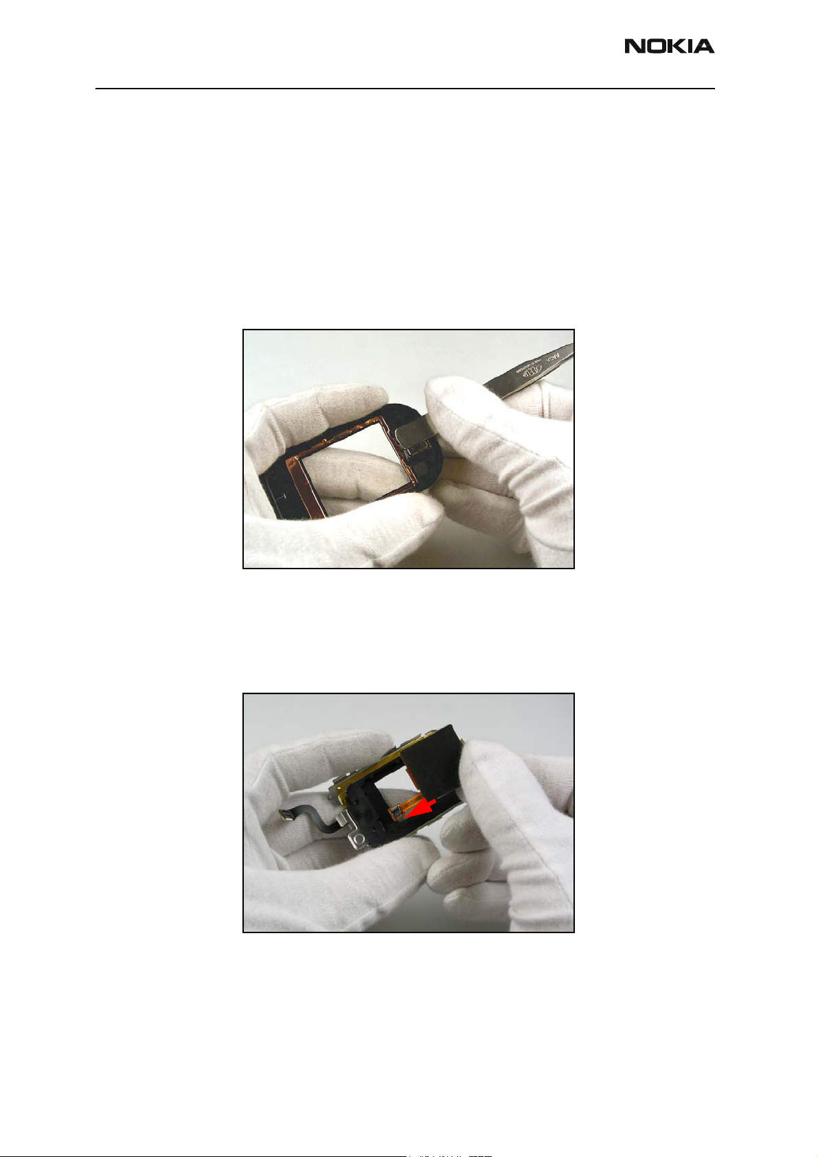
2. Install the External LCD Display
Install the external LCD display into the metal frame, pulling the flex connector through
the access hole.
Press the display into place.
Page 4 Company Confidential Issue 2 - February 2007
Page 5
2366i (RM-155)
Nokia Customer Care Assembly
Connect the earpiece flex connector.
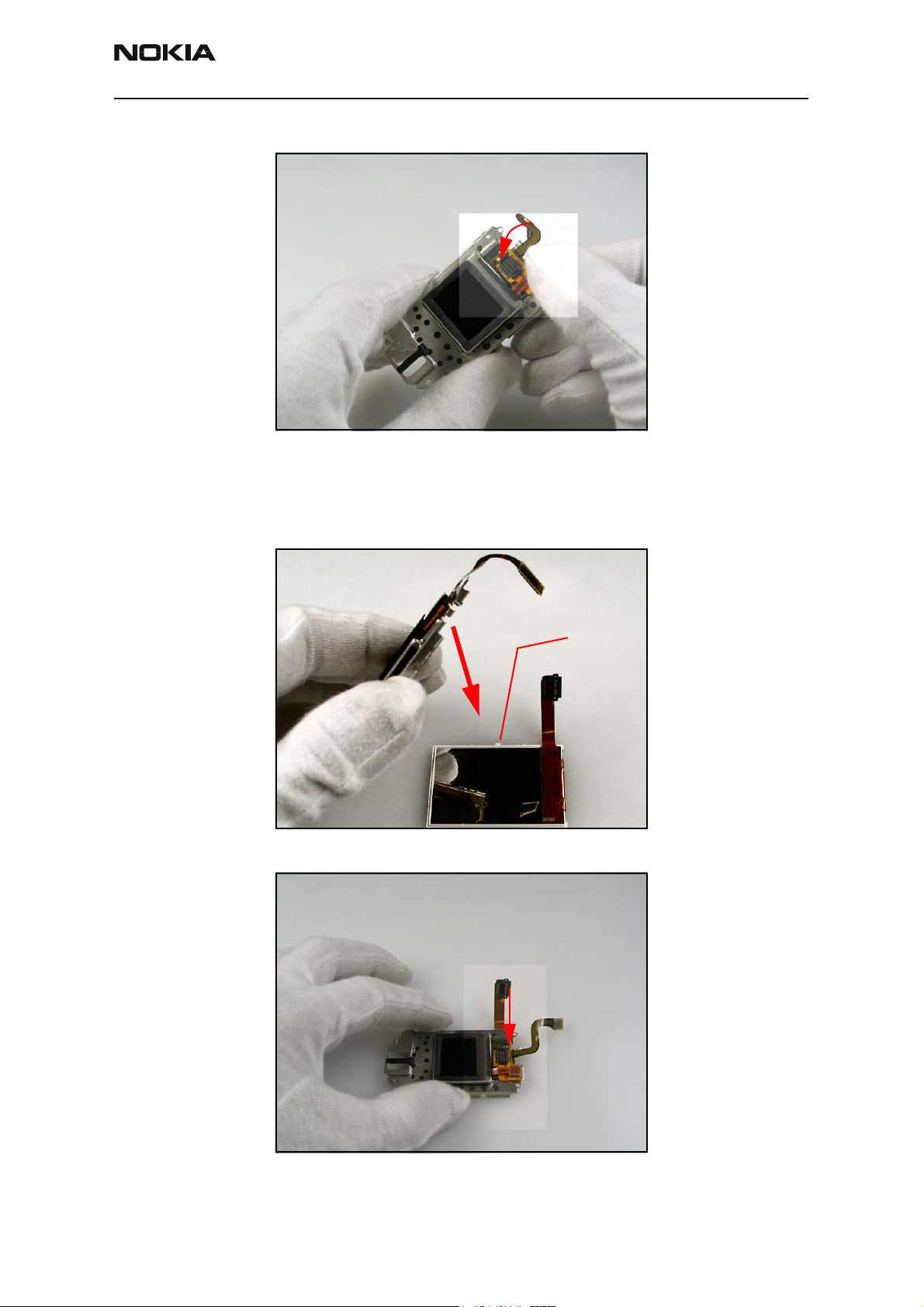
3. Install the Main LCD Display
Place the main LCD display face-down.
Align the metal frame such that it engages the six tabs on the display.
Tab (6)
Connect the main LCD flex cable.
Issue 2 - February 2007 Company Confidential Page 5
Page 6

2366i (RM-155)
Assembly Nokia Customer Care
4. Install the Upper UI into the B-cover
Install the main flex cable into the slot.
Install the upper UI assembly into the A-cover and engage the locking tabs.
Connect the main flex connector.
Install the 4 #6 Torx screws. Tighten the screws in the order shown and to the following
specifications: 13 Ncm (± 2 Ncm) / 550 RPM.
2.
3.
1.
4.
Page 6 Company Confidential Issue 2 - February 2007
Page 7

2366i (RM-155)
Nokia Customer Care Assembly
5. Assemble the Hinge
Align the slots and combine the the C-cover and B-cover.
Use tweezers to open the flip damper and allow the main flex cable to slide freely
through. Ensure that the flip damper is properly seated after routing the main flex cable.
Issue 2 - February 2007 Company Confidential Page 7
Page 8

2366i (RM-155)
Assembly Nokia Customer Care
Hold the assembly as shown.
Engage the left hinge.
Flex the C-cover and partially engage the right hinge.
Fully open the flip cover. The right hinge snaps fully into place.
Note: The hinge should operate smoothly. If there is any binding, disengage the right
hinge and ensure that the main flex cable is correctly routed and that the flip damper
is correctly seated.
Page 8 Company Confidential Issue 2 - February 2007
Page 9

2366i (RM-155)
Nokia Customer Care Assembly
6. Install the A-Cover
Engage the A-cover with the B-cover at the earpiece end.
Apply pressure equally to both sides until the locking tabs engage with a click.
Rotate the phone 180 degrees and apply pressure equally to both sides of the hinge end
until the locking tabs engage with a click.
Apply pressure to both sides of the middle area until the locking tabs engage with a click.
Note: Applying some pressure along the sides helps the locking tabs to engage.
7. Install the Sidekey
Install the sidekey into the slot on the C-cover.
Issue 2 - February 2007 Company Confidential Page 9
Page 10

2366i (RM-155)
Assembly Nokia Customer Care
8. Install the Keymat
Press the keymat into position, ensuring that the tabs engage the locating posts on the
cover.
9. Connect the Flex Connector
Connect the flex connector to the PWB.
Attach the adhesive ground connector to the pad on the PWB.
Note: ensure that the lower left corner of the adhesive ground connector is aligned
exactly with the lower left corner of the pad, and that the ground connector does not
touch any other components.
Page 10 Company Confidential Issue 2 - February 2007
Page 11

2366i (RM-155)
Nokia Customer Care Assembly
10. Install the Main PWB into the C-Cover
Install the sidekey switch assembly into the slot behind the sidekey.
Install the main PWB onto the C-cover, ensuring that the locking tabs engage with a
click.
1.
2.
Connect the main flex connector.
Note: Ensure that the connector seats with a click.
Issue 2 - February 2007 Company Confidential Page 11
Page 12

2366i (RM-155)
Assembly Nokia Customer Care
11. Install the UHJ Cover
Carefully align and press down on the flex connector until it snaps to the PWB.
12. Install the Antenna
Insert the antenna.
Install the RF grommet.
Page 12 Company Confidential Issue 2 - February 2007
Page 13

2366i (RM-155)
Nokia Customer Care Assembly
13. Install the Microphone Module
Install the microphone module into the D-cover, ensuring that no damage occurs to the
contacts.
14. Install the DC Jack
Install the DC jack into the D-cover, ensuring that no damage occurs to the contacts.
15. Install the D-cover
Align the D-cover to the C-cover.
Issue 2 - February 2007 Company Confidential Page 13
Page 14

2366i (RM-155)
Assembly Nokia Customer Care
Apply pressure to the edges to engage the locking tabs.
Install the four #4 Torx screws.
Set the correct torque: 20 Ncm (±2 Ncm) / 500 RPM.
Tighten the screws in the order shown.
Note: to prevent damage to the plastic threads, turn the screws left first, then tighten
them.
1.
4.
3.
2.
Page 14 Company Confidential Issue 2 - February 2007
Page 15

2366i (RM-155)
Nokia Customer Care Assembly
16. Install the Battery Cover
Install the battery cover and slide it toward the antenna end until the cover locks with a
click.
The assembly procedure is complete.
Issue 2 - February 2007 Company Confidential Page 15
Page 16

2366i (RM-155)
Assembly Nokia Customer Care
This page left intentionally blank.
Page 16 Company Confidential Issue 2 - February 2007
 Loading...