

Page 1

Nokia Customer Care
2366i (RM-155)
Mobile Terminal
Baseband Description and
Troubleshooting
Issue 2 - February 2007 Company Confidential ©2007 Nokia Corporation
Page 2

2366i (RM-155)
Baseband Description and Troubleshooting Nokia Customer Care
Contents Page
Introduction ..................................................................................................................................................... 4
Baseband Components.................................................................................................................................. 5
Power-Up Sequence ...................................................................................................................................7
GPS...................................................................................................................................................................... 9
GPS Troubleshooting ..................................................................................................................................9
GPS Phoenix Interface ..............................................................................................................................11
Flip Detection................................................................................................................................................ 11
Troubleshooting .........................................................................................................................................11
USB .................................................................................................................................................................. 12
USB Troubleshooting ................................................................................................................................13
USB Phoenix Interface .............................................................................................................................14
Display ............................................................................................................................................................ 14
Display Troubleshooting ..........................................................................................................................15
Display and Keypad Backlight Troubleshooting ................................................................................16
Display Phoenix Interface .......................................................................................................................17
Display Backlight Troubleshooting .......................................................................................................17
Keypad Backlight Troubleshooting .......................................................................................................18
Audio............................................................................................................................................................... 18
Audio Troubleshooting .............................................................................................................................18
Audio Phoenix Interface ..........................................................................................................................19
System Connector........................................................................................................................................ 20
Accessory Detection .................................................................................................................................21
Flash Programming ..................................................................................................................................... 21
Flashing Tool ...............................................................................................................................................21
Flashing Phoenix Interface .....................................................................................................................21
Battery Interface Circuit............................................................................................................................ 22
Charging......................................................................................................................................................... 22
Alignment ...................................................................................................................................................... 24
AMS Baseband Calibration...................................................................................................................... 24
Final UI Check............................................................................................................................................... 25
Problems During Flash and Alignment .................................................................................................. 25
No Communication - Flash .....................................................................................................................25
No Communication - Alignment ...........................................................................................................25
Failed Self Test/Calibration .....................................................................................................................25
Other Potential Problems .......................................................................................................................... 26
Mobile Terminal Does Not Power Up ...................................................................................................26
Shutdown after 32 Seconds ...................................................................................................................26
No Audio ......................................................................................................................................................26
Keypad Malfunction .................................................................................................................................26
No LCD Display ...........................................................................................................................................26
Phoenix Tools................................................................................................................................................ 27
Local Mode ..................................................................................................................................................27
Reading the Mobile Terminal ...................................................................................................
Running the Self Test ...............................................................................................................................30
Checking the Baseband Regulator/General I/O parameters ..........................................................31
Flashing the Mobile Terminal .................................................................................................................32
Flashing - EZ-Flash................................................................................................................................ 32
..............28
Page 2 Company Confidential Issue 2 - February 2007
Page 3

2366i (RM-155)
Nokia Customer Care Baseband Description and Troubleshooting
Reference ....................................................................................................................................................... 33
Signal References ......................................................................................................................................33
Issue 2 - February 2007 Company Confidential Page 3
Page 4

2366i (RM-155)
Baseband Description and Troubleshooting Nokia Customer Care
Introduction
The 2366i baseband module is a tri-mode, code division multiple access (CDMA),
dual-band engine and is based on the DCT4.5 standard. The baseband engine includes
two major Application Specific Integrated Circuits (ASICs):
• D2200 Universal Energy Management Cost Reduced Integrated Circuit (UEMCR
IC), which includes the audio circuits, charge control, and voltage regulators
• D2800 Universal Phone Processor (UPP) — Main processor, which includes system
logic for CDMA, two Digital Signal Processors (DSPs), the Main Control Unit
(MCU), and the memory.
The BL-5C Li-ion battery is the main power source, with a nominal capacity of 820 mAh.
Page 4 Company Confidential Issue 2 - February 2007
Page 5
2366i (RM-155)
Nokia Customer Care Baseband Description and Troubleshooting
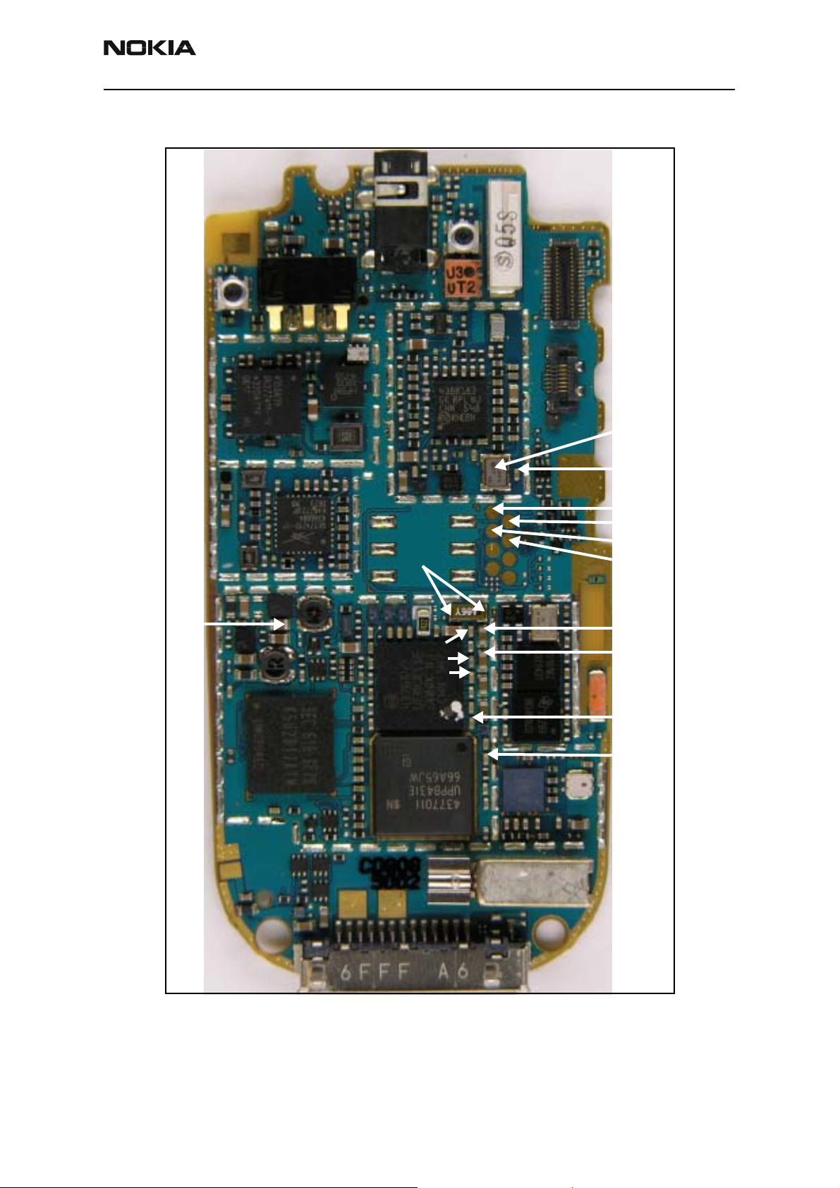
Baseband Components
G7100
VCORE
D3000
32KHz
VFlash1
D2200
D2800
VR3
VANA
19.2MHz
VPP
FBus Tx
MBus Tx/Rx
FBus Rx
VR1A
VR1B
VIO
VSIM
Figure 1: PWB - bottom side
Issue 2 - February 2007 Company Confidential Page 5
Page 6
2366i (RM-155)
Baseband Description and Troubleshooting Nokia Customer Care
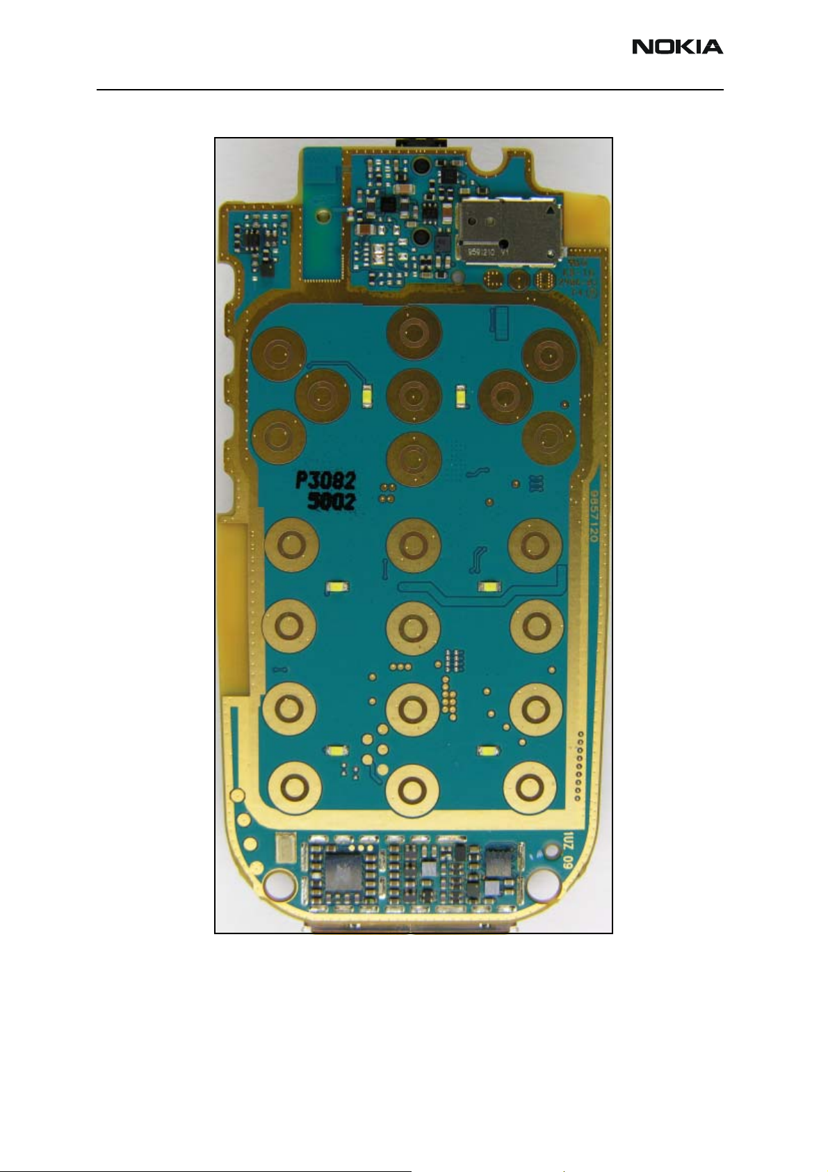
Figure 2: PWB - top side
Page 6 Company Confidential Issue 2 - February 2007
Page 7
2366i (RM-155)
Nokia Customer Care Baseband Description and Troubleshooting
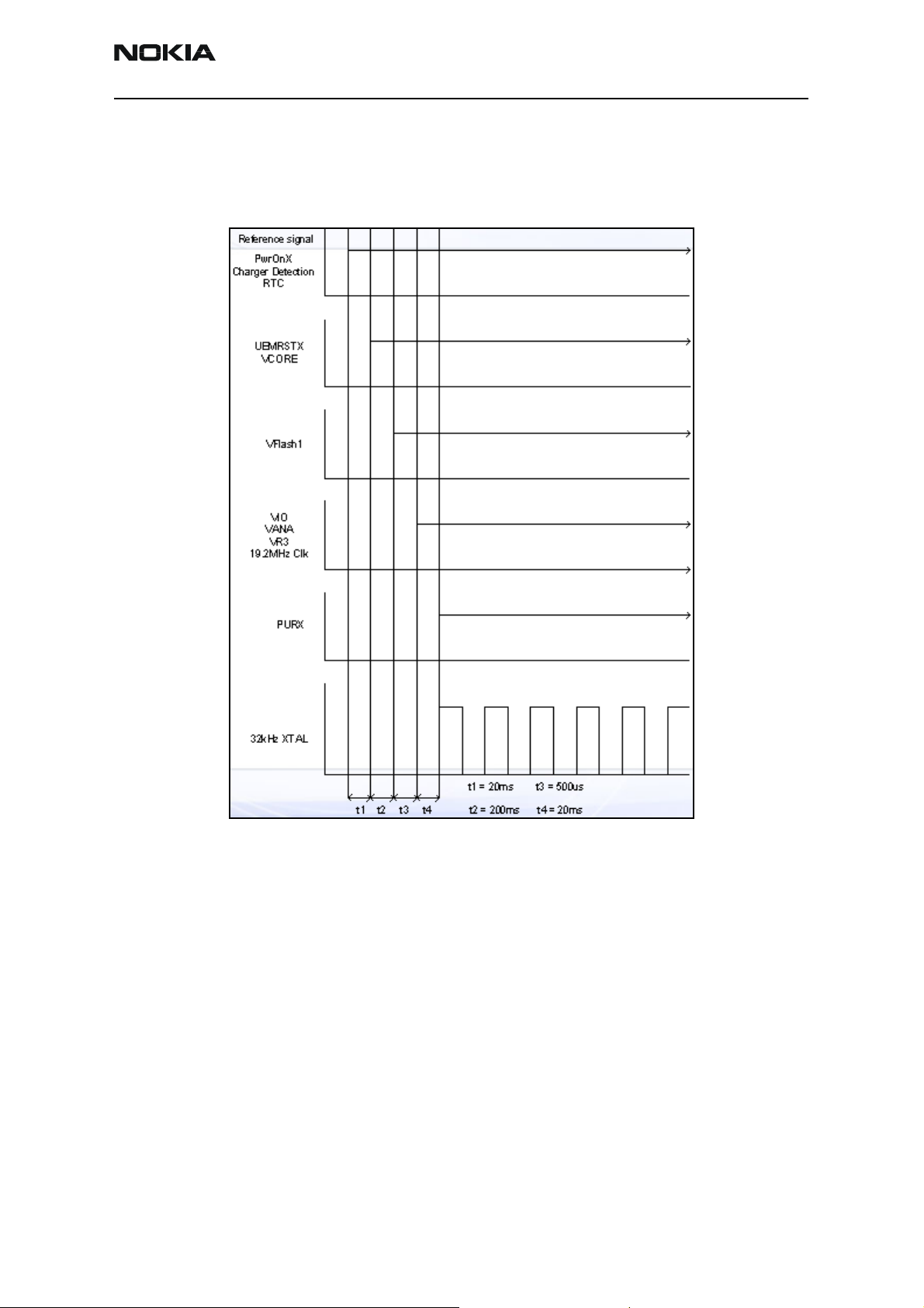
Power-Up Sequence
When the mobile terminal is dead or jammed, check the power-up sequence of the
baseband area. Verify all regulator and reset signals are correct to ensure proper power
up of the UEMCR and the UPP integrated circuits.
Reset mode is entered and the watchdog
starts. VCORE is enabled, and provides
power to the UPP.
End of settling time (only if Vbat >Vcoff+)
VFlash1 regulator is enabled.
VR3, VANA, VIO are enabled. PURX is held
low.
UPP, MCU, and DSP are reset; PURX
releases.
Figure 3: Power-up sequence and timing
Issue 2 - February 2007 Company Confidential Page 7
Page 8
2366i (RM-155)
Baseband Description and Troubleshooting Nokia Customer Care
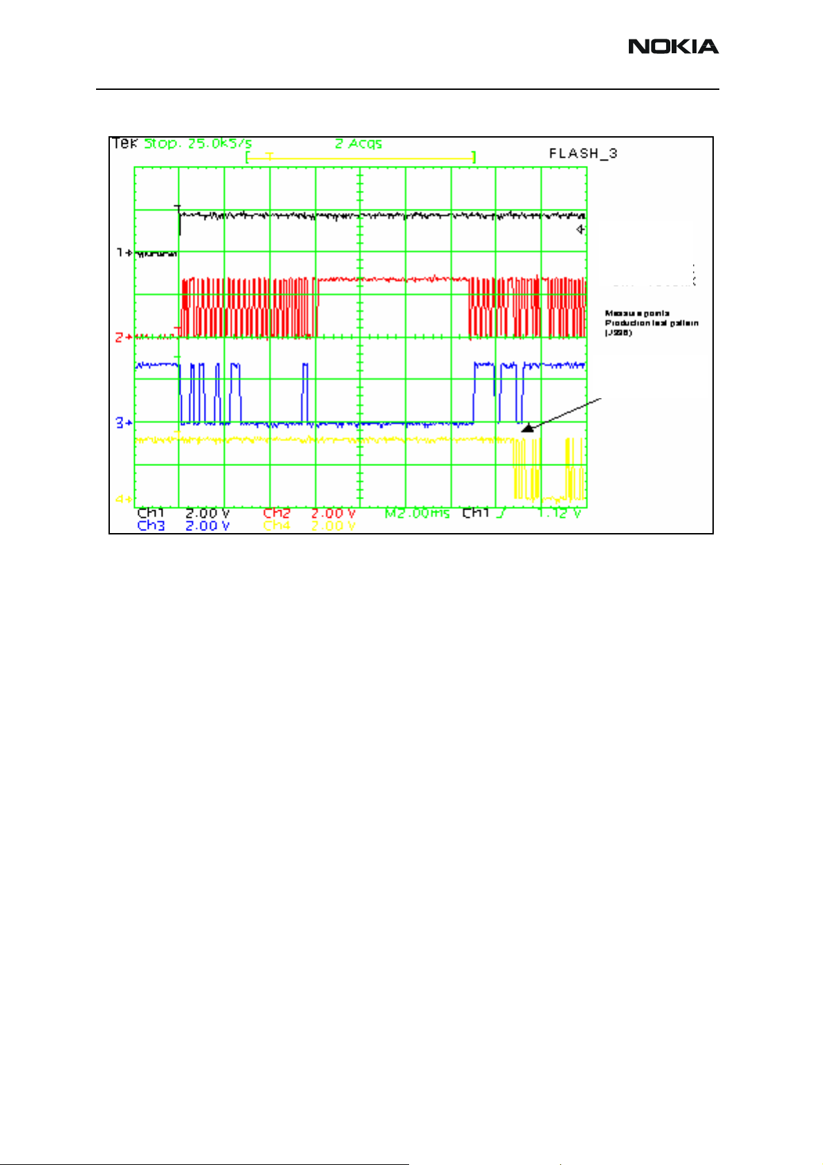
CH1- PURX
CH2-MBUS
CH3-FBUSTX
CH4-FBUSRX
Data transfer has
started (Fbus_RX)
Figure 4: Measured power-on sequence and timing - flash programming
Page 8 Company Confidential Issue 2 - February 2007
Page 9
2366i (RM-155)
Nokia Customer Care Baseband Description and Troubleshooting
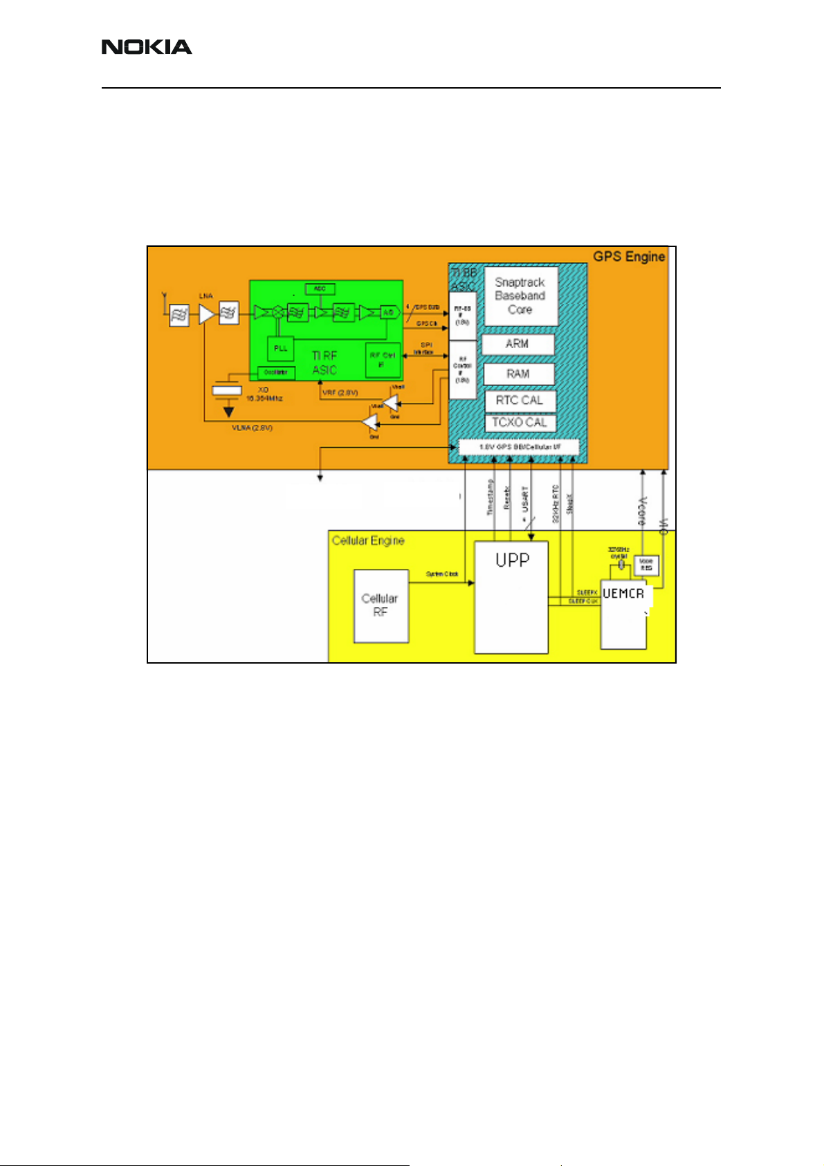
GPS
The GPS turns on by using Vcore and VIO from the UEMCR IC. The GPS communicates
with the UPP using the UART interface, turning on the GPS engine’s BB integrated circuit
and RF integrated circuit. These synchronize with the mobile terminal using the 19.2
Mhz clock. The mobile terminal computes the location coordinates from signals received
from the satellites and sends them to the emergency desk.
Secondary UARD
(Diagnostic)
Figure 5: GPS Block Diagram
System Clock
19.2 MHz (CDMA)
The GPS baseband module performs the following:
• Accepts the GPS raw data from the front end
• Processes the raw data to provide the CE with location information (2 CPUs)
• Accepts commands from the CE
• Mode (sleep, idle, etc.)
• RF control commands
• GPS configuration
• Provides power for the FPS RF
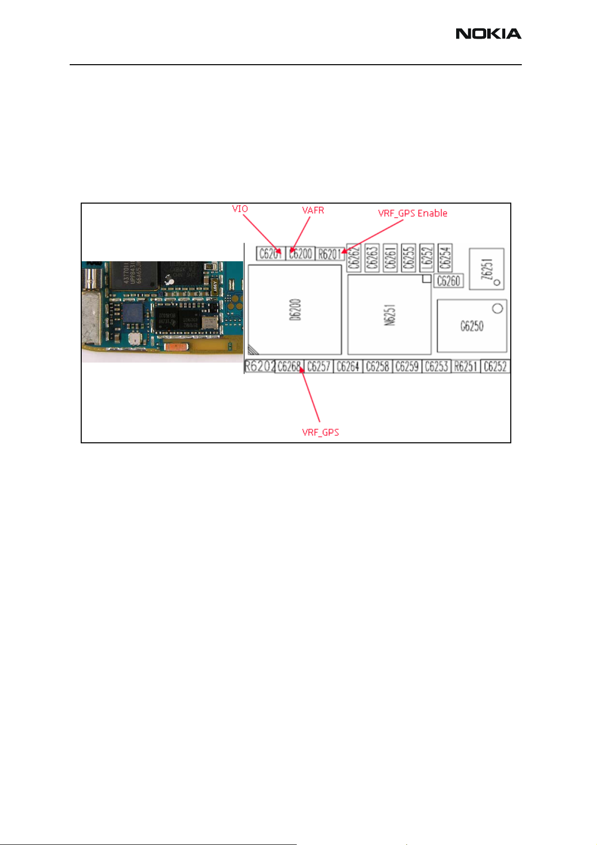
GPS Troubleshooting
Check the following connections and signals (see Figure 6):
• Power source Vcore and VIO
• CLK19M2_GPS = 19.2 Mhz
Issue 2 - February 2007 Company Confidential Page 9
Page 10
2366i (RM-155)
Baseband Description and Troubleshooting Nokia Customer Care
•VRF is enabled
• VRF_GPS =2.78 V dc
• GPS clock = 16.384 Mhz
• Use Phoenix to run Test Mode 1
• USART activity
• GPS antenna
Figure 6: RF and BB GPS integrated circuits (ICs)
• GPS_EN_RESET (1.8V)
• GPS_SLEEPCLK (32.768kHz)
Page 10 Company Confidential Issue 2 - February 2007
Page 11
2366i (RM-155)
Nokia Customer Care Baseband Description and Troubleshooting
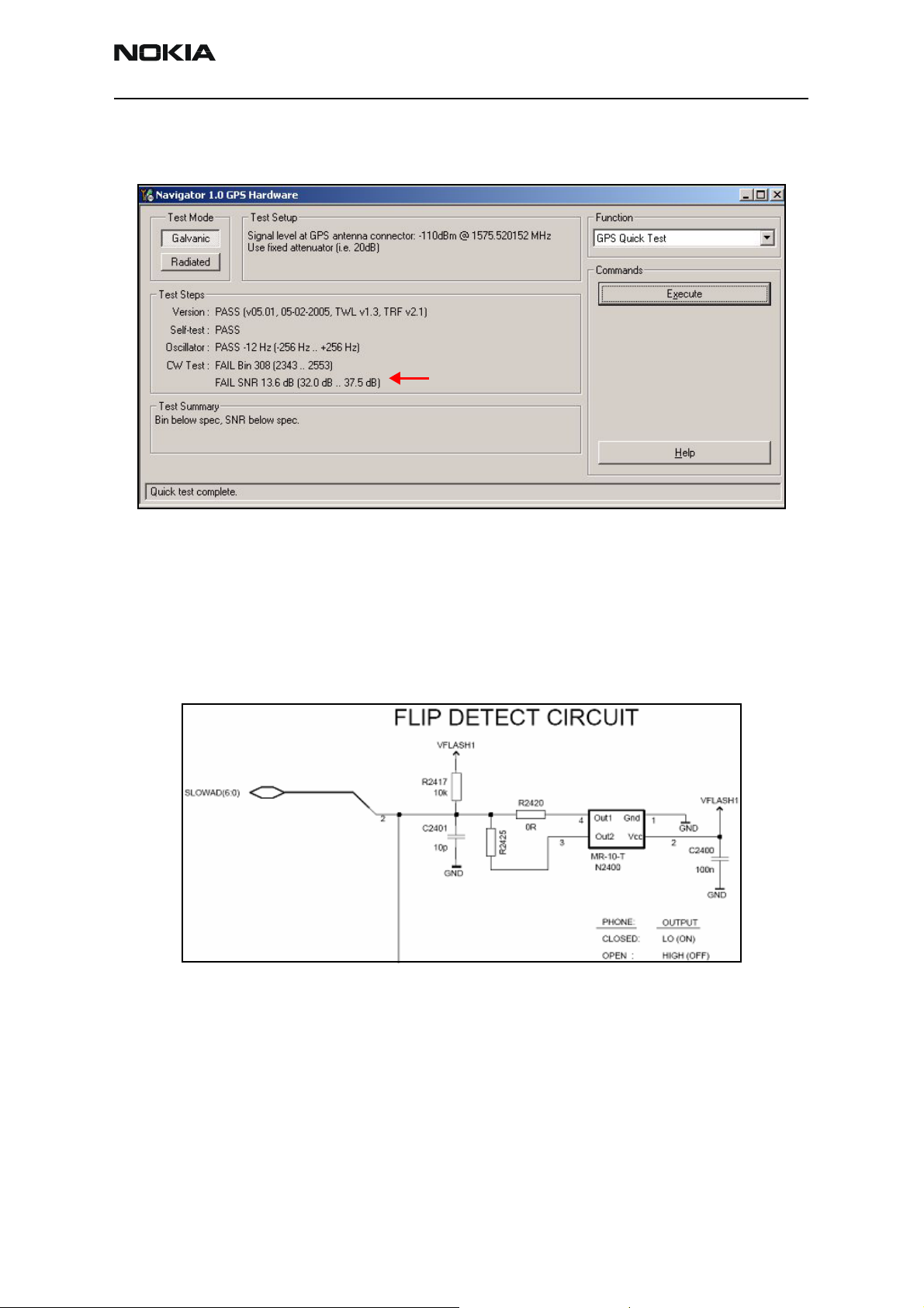
GPS Phoenix Interface
Run the GPS Quick Test in Phoenix to check the GPS BB.
CW Test fails unless CW Tone is
injected into the GPS RF Connector
Flip Detection
The Flip Detect circuit uses a Hall-effect sensor to recognize the position of the flip
cover. The sensor has an open-collector output that is pulled low when a magnetic field
of sufficient strength is present at the sensor. The sensor is located on the Baseband
PWB, and the corresponding magnet is mounted in the mechanics of the flip. See
Figure 8 for the circuit diagram.
Figure 7: Phoenix GPS Quick Test option
Figure 8: Flip detection circuit
Troubleshooting
1. Check that the components are correctly mounted and soldered.
2. Check the voltage on VFLASH1. If not present, check the UEMCR IC.
3. Check that the input to KEYB1 on the UEMCR is low.
4. Check that the magnet is correctly located with respect to the sensor.
Issue 2 - February 2007 Company Confidential Page 11
Page 12

2366i (RM-155)
Baseband Description and Troubleshooting Nokia Customer Care
USB
When the mobile terminal is connected to the computer using a DKU-2 or CA-53 data
cable, the PC provides Vbus (5V) to and pull down D+ a, d D – lines. The mobile terminal
responds by pulling the D+ line high. The PC then acknowledges and starts transferring
data at 12 Mbits/s.
Figure 9: USB block diagram
Figure 10: Pop-port system connector–Signal locations
Figure 11: PC Device Manager
Page 12 Company Confidential Issue 2 - February 2007
Page 13

2366i (RM-155)
Nokia Customer Care Baseband Description and Troubleshooting
USB Troubleshooting
When troubleshooting the USB, refer to Figure 9, Figure 10, Figure 11, and Figure 12; and
use the following procedure to check these points:
1. Connect the mobile terminal to the Phoenix flash station using a DKU-2 or
CA-53 data cable.
2. Use the Windows Device Manager to see if the mobile terminal is recognized as a
USB device. You should see something similar to Figure 13.
• If recognized, there is no hardware fault and you can stop troubleshooting.
• If not recognized, perform a visual inspection on the Pop-port connector,
ESD Protection, NUT integrated circuit, capacitors, and inductors.
3. Check for activity on the USB D+ and USB D – lines. If there is no activity, inspect
the D2800 under X-ray or change the part.
USB ESD protection
USB D+
USB D-
Figure 12: USB connections and chart
Issue 2 - February 2007 Company Confidential Page 13
Page 14

2366i (RM-155)
Baseband Description and Troubleshooting Nokia Customer Care
USB Phoenix Interface
Use the USB Tests dialog box to test the USB.
Display
The Nokia 2366i has a 128 x 160 CSTN display with 65k colors. This display is controlled
by the D2800 UPP through a parallel interface and powered by the UEMCR using VIO and
VFlash1. An ESD ASIP next to the flex connector protects against ESD.
Figure 13: USB Tests dialog box
Page 14 Company Confidential Issue 2 - February 2007
Page 15

2366i (RM-155)
Nokia Customer Care Baseband Description and Troubleshooting
Display Troubleshooting
When troubleshooting the display, refer to Figure 14, and perform the following checks:
Figure 14: Display test points and chart
1. Check that the display is connected properly and is making good contact with LCD connector. Try replacing the LCD.
2. Check the power supply output VIO and VFlash1. If not correct, check the UEMCR IC.
Issue 2 - February 2007 Company Confidential Page 15
Page 16

2366i (RM-155)
Baseband Description and Troubleshooting Nokia Customer Care
3. Check for signal activity on the LCD test points. If no activity, check or replace
the D2800 UPP IC.
4. For the internal display, check the DIF (parallel) interface.
5. The frequency of the DIF CLK signal should be 4.8 MHz.
6. For the external display, check the LCD serial interface.
7. The frequency of the LCD CLK signal should be 2.4 MHz.
Display and Keypad Backlight Troubleshooting
The display backlight uses four LEDs in series powered by an external LED driver.
Figure 15: Display and Keypad Backlight test points
Klight
Figure 16: Backlight test points - location
Page 16 Company Confidential Issue 2 - February 2007
Page 17

2366i (RM-155)
Nokia Customer Care Baseband Description and Troubleshooting
Display Phoenix Interface
Run the Display Test in Phoenix to check the display. Click Write to turn on the display
and keypad backlight.
Figure 17: Lights tab on the Display Test dialog box
Display Backlight Troubleshooting
Refer to Figure 15. When troubleshooting the display backlights, make these common
checks.
1. Perform a visual inspection of the LCD connector and the LED Driver circuitry.
2. If the display backlight does not switch on, check VLED + (approximately 9 V dc)
for the main display, VLED 2+ for the external display, and VLED - (approximately
0,5 V dc) for both.
3. If the signals in the preceding step are correct, then the LED Driver IC is working
properly, and the LED inside the display may have a malfunction. Try replacing
the display.
4. If the signals are not correct, then check VLED +, VLED2+, and VLED-.
5. Check that the Klight signal is enabled (high - approximately +4 V dc) for the
external LCD. If not correct, check the UEMCR.
6. Check that the FDC signal is high (approximately 2.0 V dc) to turn on the internal
LCD and the keypad backlight LEDs. If the signal is not correct, check Vflash1 and
FLIP DETECT output.
7. Check Vbat (approximately 4 V dc) and Vin (approximately 4 V dc) are present on
the LED driver inputs. If not, check the connection to the power supply.
Issue 2 - February 2007 Company Confidential Page 17
Page 18

2366i (RM-155)
Baseband Description and Troubleshooting Nokia Customer Care
Keypad Backlight Troubleshooting
Refer to Figure 15. When troubleshooting the keypad backlight, make these common
checks.
1. Perform a visual inspection of the LCD connector and the all the components,
including the LEDs.
2. Check Vbat to ensure that the LED Driver IC has power.
3. Check the Klight signal to ensure that the driver is enabled by the UEMCR IC. If
not, check the UEMCR IC.
4. If the lights are too dim or too bright, check the current setting resistors. Resistor
Rset controls the current going through the LEDs.
5. Check the output of the LED Driver to ensure that the LEDs are receiving power. If
the output voltage is present, replace the LED.
Audio
The Baseband PWB supports three microphone inputs and two earpiece outputs. The
microphone inputs are:
• MIC1 - used for the mobile terminal's internal microphone
• MIC2 - used for headsets connected to the Pop-port connector
• MIC3 - used for the Universal Headset connected to the Universal Headset Jack
(UHJ).
Each microphone input can have either a differential or single-ended AC connection to
the UEMCR circuit. The internal microphone (MIC1) and external microphone (MIC2) for
are both differential for Pop-port accessory detection. However, the Universal Headset
interface is single ended. The microphone signals from different sources are connected to
separate inputs at the UEMCR IC. Inputs for the microphone signals are differential
types. Also, MICB1 is used for MIC1, and MICB2 is used for MIC2 and MIC3 (Universal
Headset).
Audio Troubleshooting
Use the following to troubleshoot the audio:
1. Check for bad contacts or a damaged earpiece.
2. Check for bad connections at the mic, and ensure that the Audio ASIP is OK.
3. Check for broken or bad solder joints on passive components.
4. Verify the audio signal paths, using “BaseBand audio control” feature of Phoenix
See "Audio Phoenix Interface"onpage19.
Page 18 Company Confidential Issue 2 - February 2007
Page 19

2366i (RM-155)
Nokia Customer Care Baseband Description and Troubleshooting
Audio Phoenix Interface
Run the audio test in Phoenix to check the audio functionality.
MIC3
MIC1
MIC2s
Earpiece
IHF
Figure 18: Audio Test in Phoenix
Table 1: Audio Test Parameters
Audio Component Description
MIC1 Routes the audio from the internal microphone to the headset speaker.
MIC2 Routes the audio signal from the headset microphone to the internal earpiece.
MIC3 Use the first and second options on the Phoenix menu to have an open channel. When
you insert the Universal Headset, the UEM automatically reroutes the audio signal to
the UHJ.
Earpiece Allows you to use to hear a signal from the internal earpiece.
IHF Routes the audio signal to the IHF speaker output.
Issue 2 - February 2007 Company Confidential Page 19
Page 20

2366i (RM-155)
Baseband Description and Troubleshooting Nokia Customer Care
System Connector
The system connector is the Pop-port connector as shown in Figure 19. The mobile
terminal supports Pop-port (differential) and Universal Headset (single-ended)
accessories. The ACI signal detects the Pop-port accessory, while TIKU_GENIO(4) signal
detects the Universal Headset.
Figure 19: System Connector
There are 14 circuits connected through the system connector:
• Charge = Connects to the charging system
• Charge GND = Grounds the charging system
• ACI = Accessory Control Interface
• Vout = External accessory power supply
• USB Vbus = USB power supply (5V)
• USB D+ = USB data line (positive)
• USB D- = USB data line (negative)
• XMIC N = Differential connection to the MIC for the external microphone
• XMIC P = Differential connection to the MIC for the external microphone
• HSEAR N = Differential headset connection to the external EAR
• HSEAR P = Differential headset connection to the external EAR
• HSEAR R N = Differential headset connection to the external stereo
• HSEAR R P = Differential headset connection to the external stereo
Page 20 Company Confidential Issue 2 - February 2007
Page 21

2366i (RM-155)
Nokia Customer Care Baseband Description and Troubleshooting
Accessory Detection
Figure 20 shows how the mobile terminal detects accessories. Dumb accessories pull
down to the GND ACI Line. Smart accessories pull down the ACI line with a 56K Ohm
resistor allowing communication between the accessory and the UEMCR.
VFLASH1 (2.78V)
VAUX2 (2.78V)
Figure 20: Accessory Detection Diagram
Flash Programming
Flashing Tool
• BSI = Used to indicate to the MCU that the prommer is connected and the mobile
terminal is in flashing mode.
• MBUS = Used as a clock signal for synchronizing the serial communication
between the prommer and the MCU.
• FBUSRX = Data to the D2800.
• FBUSTX = Data to the prommer.
• VPP = 0v/1.8v/8.8V (read only/normal operation or slow programming/fast
programming).
Flashing Phoenix Interface
1. Run EZ Flash in Phoenix to flash the mobile terminal.
Figure 21: EZ Flash in Phoenix
Issue 2 - February 2007 Company Confidential Page 21
Page 22

2366i (RM-155)
Baseband Description and Troubleshooting Nokia Customer Care
2. Click Select to search for the appropriate software.
Figure 22: EZ Flash in Phoenix
3. After selecting the correct software package, click Flash to write the software to
the mobile terminal.
Battery Interface Circuit
Check the battery BSI voltage levels in the following power up modes:
• Normal mode: 1.23V
• Test mode: 170mV
• Local mode: 90mV
Charging
Use the following items to troubleshoot charging issues. See Figure 23 and Table 2.
1. Ensure that the battery is good.
2. Measure the voltage across the diode; the voltage should be greater than
3.0 V dc.
3. Use Phoenix to ensure that the BTEMP ADC is ~25 C. If not, re-calibrate the
phone.
4. Remove the fuse at F2000, and measure the current with an AC-3. If it is not
~850mA, replace the UEMCR IC.
Page 22 Company Confidential Issue 2 - February 2007
Page 23

2366i (RM-155)
Nokia Customer Care Baseband Description and Troubleshooting
Figure 23: Charging troubleshooting diagram
Issue 2 - February 2007 Company Confidential Page 23
Page 24

2366i (RM-155)
Baseband Description and Troubleshooting Nokia Customer Care
Table 2: Charger detection levels
Voltage level Minimum Typical Maximum
VCHdet+ 1.9 V dc 2.0 V dc 2.1 V dc
VCHdet- 1.7 V dc 1.8 V dc 1.9 V dc
VBATlim1+ 3.54 V dc 3.65 V dc 3.76 V dc
VBATlim1- 3.32 Vdc 3.50 V dc 3.66 V dc
VBATlim2 + 4.85 V dc 5.0 V dc 5.15 V dc
VTAB lim2 - 4.63 V dc 4.85 V dc 5.05 V dc
Alignment
Alignment consists of using the production Flali station to check the following:
• Initial current for quick short circuit detection
• Flashing the mobile terminal
• Baseband self-test for integrity check circuit interconnections
• Baseband calibrations:
•ADC
•VBAT
• VCHAR and ICHAR
•BSI
•Btemp
• RF calibrations
AMS Baseband Calibration
Use the AMS baseband calibration to perform the following tests:
• ADC - Verify and calibrate the gain and offset for 11 channels analog to digital
converter in the UEM.
• VBAT - Calibrate the gain and offset of the battery input path for accurate
battery level monitoring.
• VCHAR and ICHAR – Verify the charging circuit and path calibrate gain and
offset for correct charger detection.
• BSI – Calibrate the gain of the BSI line for battery size information upon
powering up.
• Btemp – Calibrate gain of Btemp for battery temperature monitoring during
charging for over temperature shut down.
Page 24 Company Confidential Issue 2 - February 2007
Page 25

2366i (RM-155)
Nokia Customer Care Baseband Description and Troubleshooting
Final UI Check
Final UI performs basic user interface, audio and accessory tests on the baseband:
• Ensures that all keymats work.
• Ensures that the internal mic and earpiece work.
• Checks that the LCD module is functioning correctly.
• Ensures that all the external system and charger contacts are properly assembled.
• Ensure that general call processing is correct.
Problems During Flash and Alignment
The following topics discuss potential problems that can occur during Flash and
Alignment.
No Communication - Flash
Ensure a good connection between the flash adaptor and mobile terminal.
• You must power the mobile terminal by a prommer (e.g., FPS-8).
• Check the baseband regulators: VR3, VIO, VCORE, VFLASH1.
• You must have 19.2Mhz clock into the D2800 in order to flash the mobile
terminal.
• Check the BSI, MBUS, FBUSRx, FBUSTx, PURX, SLEEPX for bad solder joints
between the UEM and the D2800.
• Check the flash bus signal and VPP voltage level.
No Communication - Alignment
• Check all connections between the test fixture, cables, and the mobile terminal.
• Make sure the mobile terminal is in Local Mode, and check the VBAT voltage and
current levels. If not in Local Mode, check the BSI signal level.
• Make sure mobile terminal was programmed/Flashed.
Failed Self Test/Calibration
• Make sure the mobile terminal is in Local Mode.
• Make sure power supply provides enough current (~500mA and 2A for tuning).
• Use the troubleshooting guide’s troubleshooting flow chart to verify the failed
circuit.
• Check the signals and voltage levels.
Issue 2 - February 2007 Company Confidential Page 25
Page 26

2366i (RM-155)
Baseband Description and Troubleshooting Nokia Customer Care
Other Potential Problems
Mobile Terminal Does Not Power Up
• Check the baseband regulators – VR3, VIO, VFLASH1, VCORE dc/dc, PURX.
• Check VCTCXO 19.2MHz signal at the D2800 input.
• Check the power up sequence.
• Check Flash IC, flash bus signals, and voltage level.
Shutdown after 32 Seconds
• Check for the absence of 32KHz SleepCLK.
• Check for incorrect SleepX and PURX signal levels.
• Check if the ESN number was corrupted.
No Audio
• Check for bad contacts or damaged earpiece
• Check for bad connections at the microphone
• Check for broken or bad solder joint of transistors and audio ASIPs
• Verify the audio signal paths using baseband “audio test” component with
Phoenix
Keypad Malfunction
• Check for protective film left on the back of the key dome if a new one was
installed
• Check for corrosion on the keypad and keydome
• Check if the flash software was corrupted
• Check for a bad joint from the D2800 to the Z2400 interface
• Check for damage on the Z2400
No LCD Display
• Check for bad connections
• Check for a cracked or damaged display
• Probe test points for missing or incorrect signal levels
Page 26 Company Confidential Issue 2 - February 2007
Page 27

2366i (RM-155)
Nokia Customer Care Baseband Description and Troubleshooting
Phoenix Tools
The Phoenix software program provides testing and service of Nokia mobile terminals.
The following section provides information about the Phoenix software and how you can
use it to troubleshoot and correct problems in the baseband component of the mobile
terminal.
Local Mode
Although most Nokia mobile terminals automatically come up in Local Mode, ensure the
mobile terminal setting is set to Local Mode.
Figure 24: Phoenix Software Main Window
Figure 25: Setting Local Mode in Phoenix
Issue 2 - February 2007 Company Confidential Page 27
Page 28

2366i (RM-155)
Baseband Description and Troubleshooting Nokia Customer Care
Reading the Mobile Terminal
To retrieve the software information in the mobile terminal, use the following procedure
Figure 26: File menu in Phoenix
1. Open the File menu, and click Scan Product. Phoenix scans the product and
displays the applicable menus and commands.
Page 28 Company Confidential Issue 2 - February 2007
Page 29

2366i (RM-155)
Nokia Customer Care Baseband Description and Troubleshooting
Figure 27: Phone Information Window in Phoenix
2. After Phoenix retrieves the mobile terminal information, the menu structure
changes to meet the requirements and settings of the mobile terminal. Save the
mobile terminal file to the computer in case you need to retrieve it later.
Issue 2 - February 2007 Company Confidential Page 29
Page 30

2366i (RM-155)
Baseband Description and Troubleshooting Nokia Customer Care
Running the Self Test
Running the Self Test is one way of quickly finding where a problem might be in the
mobile terminal.
1. Open the Testing menu, and click Self Test.
Figure 28: Self Test Command in Phoenix
2. The Self Test window appears. Click Start to initiate the self test.
Figure 29: Self Tests Command in Phoenix
Page 30 Company Confidential Issue 2 - February 2007
Page 31

2366i (RM-155)
Nokia Customer Care Baseband Description and Troubleshooting
Checking the Baseband Regulator/General I/O parameters
1. To view the baseband regulator and general I/O parameters, open the Testing
menu, point to BB/Hdw (Baseband/Hardware), and click the appropriate
command.
Figure 30: Baseband Regulator/General I/O Command in Phoenix
2. Click Get All to display all of the parameters.
Figure 31: Baseband Regulator/General I/O Command in Phoenix
Issue 2 - February 2007 Company Confidential Page 31
Page 32

2366i (RM-155)
Baseband Description and Troubleshooting Nokia Customer Care
Flashing the Mobile Terminal
To flash the mobile terminal, open the Flashing menu and select the appropriate menu
command.
Figure 32: Flashing Menu
Flashing - EZ-Flash
1. To EZ-Flash the mobile terminal, open the Flashing menu, and click EZ-Flash.
Figure 33: EZ Flash Command in Phoenix
2. After retrieving the file, click Flash to begin flashing the mobile terminal.
Page 32 Company Confidential Issue 2 - February 2007
Page 33

2366i (RM-155)
Nokia Customer Care Baseband Description and Troubleshooting
Reference
Signal References
Figure 34: Signal references 1
Issue 2 - February 2007 Company Confidential Page 33
Page 34

2366i (RM-155)
Baseband Description and Troubleshooting Nokia Customer Care
Figure 35: Signal references 2
Page 34 Company Confidential Issue 2 - February 2007
Page 35

2366i (RM-155)
Nokia Customer Care Baseband Description and Troubleshooting
Issue 2 - February 2007 Company Confidential Page 35
Page 36

2366i (RM-155)
Baseband Description and Troubleshooting Nokia Customer Care
This page intentionally left blank.
Page 36 Company Confidential Issue 2 - February 2007
 Loading...