

Page 1

Nokia Customer Care
2366i (RM-155)
Mobile Terminals
Antenna Description and
Troubleshooting
Issue 2 - February 2007 Company Confidential
Page 2
2366i (RM-155)
Antenna Description and Troubleshooting Nokia Customer Care
Contents Page
Introduction ..................................................................................................................................................... 3
CDMA Antenna Assembly............................................................................................................................. 4
Remove the CDMA Antenna Assembly ..................................................................................................5
Circuit Description ......................................................................................................................................6
Damaged RF Feed Contact ........................................................................................................................ 6
Damaged RF Connector .............................................................................................................................7
GPS Antenna .................................................................................................................................................... 8
Expose the GPS Antenna Circuits ...........................................................................................................8
Malfunctions .................................................................................................................................................8
GPS Matching Components ......................................................................................................................9
Bluetooth Antenna...................................................................................................................................... 11
Page 2 Company Confidential Issue 2 - February 2007
Page 3

2366i (RM-155)
Nokia Customer Care Antenna Description and Troubleshooting
Introduction
This chapter addresses potential failures that affect antenna performance of the 2366i
mobile terminals and discusses methods for correction of these failures. There are three
serviceable antennas used in the 2366i mobile terminal:
• CDMA antenna (a dual-band stub antenna)
• GPS antenna (mounted to the main PWB)
• Bluetooth antenna (a printed trace on the main PWB)
The following sections describe these antennas and their connections to the mobile
terminal components.
Issue 2 - February 2007 Company Confidential Page 3
Page 4
2366i (RM-155)
Antenna Description and Troubleshooting Nokia Customer Care
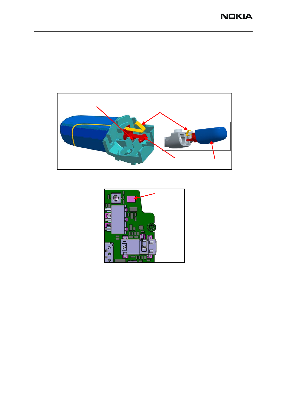
CDMA Antenna Assembly
You can disconnect the dual-band CDMA antenna assembly. Partial disassembly of the
mobile terminal is required to remove and replace the CDMA antenna assembly. (See the
Disassembly and Assembly chapters for instructions.) When installed, a T-shaped locking
tab on the antenna assembly engages two locking ramps molded into the D-cover and an
electrical spring clip contact connects to a pad on the main PWB. Figure 1 shows the
antenna assembly and its mounting arrangement.
Locking
ramps
Figure 1: CDMA Antenna Assembly and mounting arrangement
Antenna pogo pins
Spring Clip Contact
Locking Tab
Antenna Contact Pad
CDMA Antenna
Assembly
Figure 2: Antenna Contact Pad
Page 4 Company Confidential Issue 2 - February 2007
Page 5

2366i (RM-155)
Nokia Customer Care Antenna Description and Troubleshooting
Remove the CDMA Antenna Assembly
Perform the following steps to remove the CDMA Antenna Assembly:
1. Remove the battery cover. Press down on the cover while sliding it away from the
body of the mobile terminal.
Figure 3: Removal of the Battery Cover
2. If installed, remove the battery.
3. Remove the RF grommet.
Figure 4: Antenna Grommet
Issue 2 - February 2007 Company Confidential Page 5
Page 6

2366i (RM-155)
Antenna Description and Troubleshooting Nokia Customer Care
4. Remove the antenna. Use a dental pick to lift the retaining latch. Do not cause
damage to the contacts.
Figure 5: Disconnection of the Antenna (1)
Figure 6: Disconnection of the Antenna (2)
Circuit Description
Refer to Figure 7. The output of the diplexer is fed through RF connector X7300 and
through a zero-ohm resistor R7358 to the antenna contact pad on the main PWB. The
RF choke L7303 drains static charges to ground, protecting the preceding circuitry from
electrostatic damage (ESD). If a test cable is inserted into RF connector X7300, a
mechanical switch is opened, disconnecting diplexer Z7302 from the antenna contact
pad.
Damaged RF Feed Contact
The CDMA antenna assembly has a metal spring clip that makes contact with an antenna
contact pad on the main PWB. If the spring clip is damaged such that it does not make
contact with the pad, then replace the CDMA antenna assembly. If the pad is damaged,
replace the main PWB. If the contact does not make good contact with the pad, then the
antenna gain is reduced by -25 dB.
Page 6 Company Confidential Issue 2 - February 2007
Page 7

2366i (RM-155)
Nokia Customer Care Antenna Description and Troubleshooting
Damaged RF Connector
• The RF connector contains a switch. If this switch fails, there is a loss of
continuity between the input to the diplexer and the CDMA antenna, resulting in
a gain reduction of approximately -25 dB.
• Measure the DC continuity through the CDMA RF connector with no cable
connected. See Figure 7 and Figure 8 for the location of this connector. If there is
no DC continuity, replace CDMA RF connector X7300.
CDMA RF Connector
Antenna Contact Pad
CDMA RF Connector
Figure 7: CDMA Antenna Circuit
Figure 8: D-cover Removed
Issue 2 - February 2007 Company Confidential Page 7
Page 8

2366i (RM-155)
Antenna Description and Troubleshooting Nokia Customer Care
GPS Antenna
The GPS Antenna is a ceramic chip soldered onto the Main PWB. The antenna must be
mounted exactly as shown in the figure, or the antenna does not operate correctly. RF
choke L6253 acts as an ESD protection, draining static charges to ground. C6256 tunes
the antenna. When a test connector is inserted into RF Connector X6250, an internal
switch disconnects the filter from the GPS antenna circuits.
GPS RF Connector
Filter
Figure 9: GPS Antenna Circuit
Expose the GPS Antenna Circuits
Refer to the Disassembly chapter to remove the D-cover and expose the GPS antenna
circuits for troubleshooting.
Malfunctions
Figure 10 shows the mounting orientation of the GPS antenna and the matching circuits.
Check the following items to troubleshoot the GPS antenna circuits:
• If the GPS antenna looks damaged, or is missing, install a new antenna.
• Check the orientation of the antenna against that shown in Figure 10, and
correctly install a new antenna if the orientation is not correct.
• The RF connector contains a switch. If this switch fails, there is a loss of
continuity between the input to the Filter and the GPS antenna, resulting in a
gain reduction of approximately -20 dB. Measure the DC continuity through the
GPS RF Connector with no cable connected. See Figure 11 for the location of this
connector. If there is no DC continuity, replace GPS RF connector X6250.
RF ChokeTuning Capacitor
Page 8 Company Confidential Issue 2 - February 2007
Page 9

2366i (RM-155)
Nokia Customer Care Antenna Description and Troubleshooting
GPS Antenna
Ground
Figure 10: GPS Antenna and mounting arrangement
Figure 11: GPS RF Connector (GPS Antenna removed)
GPS Matching Components
Figure 12 shows the impedance-matching components for the GPS antenna circuit.
Ensure that these components are properly installed and that the correct part number is
used, as value and size are critical.
Feed
Ground
GPS RF Connector
Issue 2 - February 2007 Company Confidential Page 9
Page 10

2366i (RM-155)
Antenna Description and Troubleshooting Nokia Customer Care
6,2 nH, NMP code
3649051
2.2 pF
NMP code
2320523
Front Side
Rear Side
Figure 12: Matching components—GPS Antenna circuit
Page 10 Company Confidential Issue 2 - February 2007
Page 11

2366i (RM-155)
Nokia Customer Care Antenna Description and Troubleshooting
Bluetooth Antenna
The Bluetooth antenna, shown in Figure 13, is mounted on the main PWB. A 6.8 nH
inductor is used as a tuning component. Ensure that the antenna is correctly mounted on
the PWB. If the antenna is reversed, it does not function.
CDMA antenna
matching network
GPS pogo pins
Figure 13: Main PWB - Bluetooth Antenna
Issue 2 - February 2007 Company Confidential Page 11
Page 12

2366i (RM-155)
Antenna Description and Troubleshooting Nokia Customer Care
This page intentionally left blank.
Page 12 Company Confidential Issue 2 - February 2007
 Loading...