

Page 1

Nokia Customer Care
2366i (RM-155)
Mobile Terminals
Disassembly
Issue 2 - February 2007 Company Confidential
Page 2
2366i (RM-155)
Disassembly Nokia Customer Care
Contents Page
Safety Information......................................................................................................................................... 3
ESD Protection .............................................................................................................................................3
Disassembly Instructions.............................................................................................................................. 4
1. Remove the Battery Cover ...................................................................................................................4
2. Remove the Grommets and Screws ................................................................................................... 4
3. Separate the D-cover from the C-cover ...........................................................................................5
4. Remove the Main PWB ......................................................................................................................... 5
5. Remove the Sidekey Switch Assembly ..............................................................................................6
6. Remove the UHJ Cover ..........................................................................................................................7
7. Remove the Microphone Module .......................................................................................................7
8. Remove the DC Jack ...............................................................................................................................8
9. Remove the Antenna. ............................................................................................................................8
10. Remove the Keymat and the Sidekey .............................................................................................9
11. Disengage the Hinge Assembly ......................................................................................................10
12. Separate the A-cover from the B-cover ......................................................................................11
13. Remove the Flex Connections ........................................................................................................12
14. Disassemble the Upper UI Assembly .............................................................................................12
15. Disassemble the External Display ..................................................................................................13
16. Remove the Earpiece .........................................................................................................................14
Page 2 Company Confidential Issue 2 - February 2007
Page 3
2366i (RM-155)
Nokia Customer Care Disassembly
Safety Information
Adhere to the following guidelines when assembling and disassembling the mobile
terminal:
•QUALIFIED SERVICE
Only qualified personnel may install or repair mobile terminal equipment.
• ACCESSORIES AND BATTERIES
Use only approved accessories and batteries. Do not connect incompatible
products.
• CONNECTING TO OTHER DEVICES
When connecting to any other device, read its user’s guide for detailed safety
instructions. Do not connect incompatible products.
ESD Protection
Nokia requires that mobile terminal repair centers have sufficient ESD protection against
static electricity when servicing mobile terminals. Use the following guidelines:
• A mobile terminal that is ready for use can be handled normally without ESD
protection. The battery can be replaced in normal conditions of use.
• Use ESD protection when replacing a color cover, except for the mobile terminal
covers which can be replaced by the customer.
• All electronic parts of the mobile terminal, including the display, are susceptible
to ESD. Resistors also can be damaged by static electricity discharge.
• All ESD-sensitive parts must be packed in metallized protective bags during
shipping and handling outside any ESD Protected Area (EPA).
• Every repair action involving opening the mobile terminal or handling the mobile
terminal components must be done under ESD protection.
• ESD-protected spare part packages MUST NOT be opened/closed outside an EPA.
For more detailed information about ESD protection and EPAs, contact your local Nokia
Customer Care representative.
Issue 2 - February 2007 Company Confidential Page 3
Page 4
2366i (RM-155)
Disassembly Nokia Customer Care
Disassembly Instructions
Use the following steps to disassemble the mobile terminal.
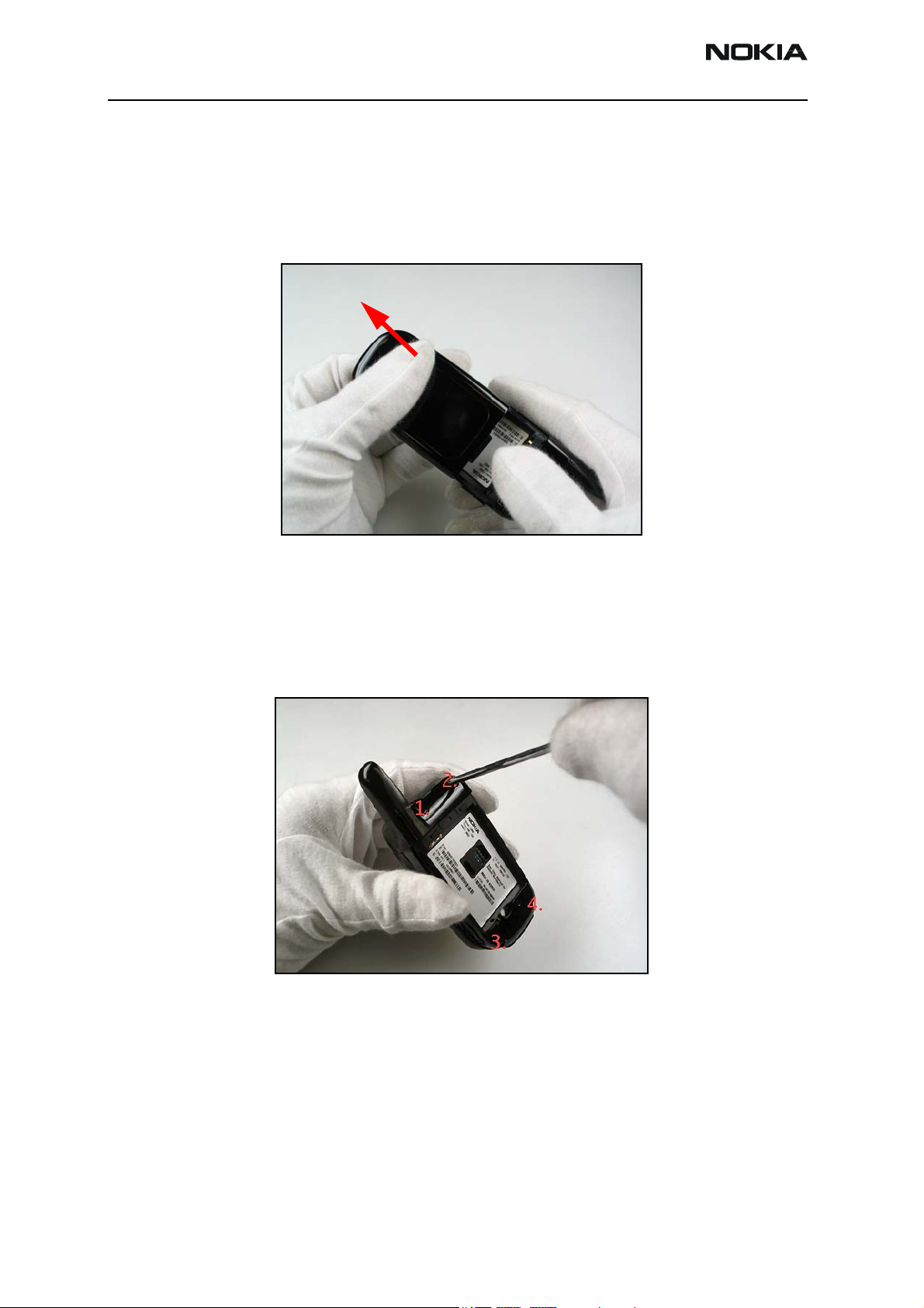
1. Remove the Battery Cover
Press down on the B-cover while sliding it away from the body of the mobile terminal.
If installed, remove the battery.
2. Remove the Grommets and Screws
Use a dental pick to remove the two grommets at positions 1 and 2.
Use a #6 Torx screwdriver to remove the 4 screws in the order shown.
Page 4 Company Confidential Issue 2 - February 2007
Page 5
2366i (RM-155)
Nokia Customer Care Disassembly
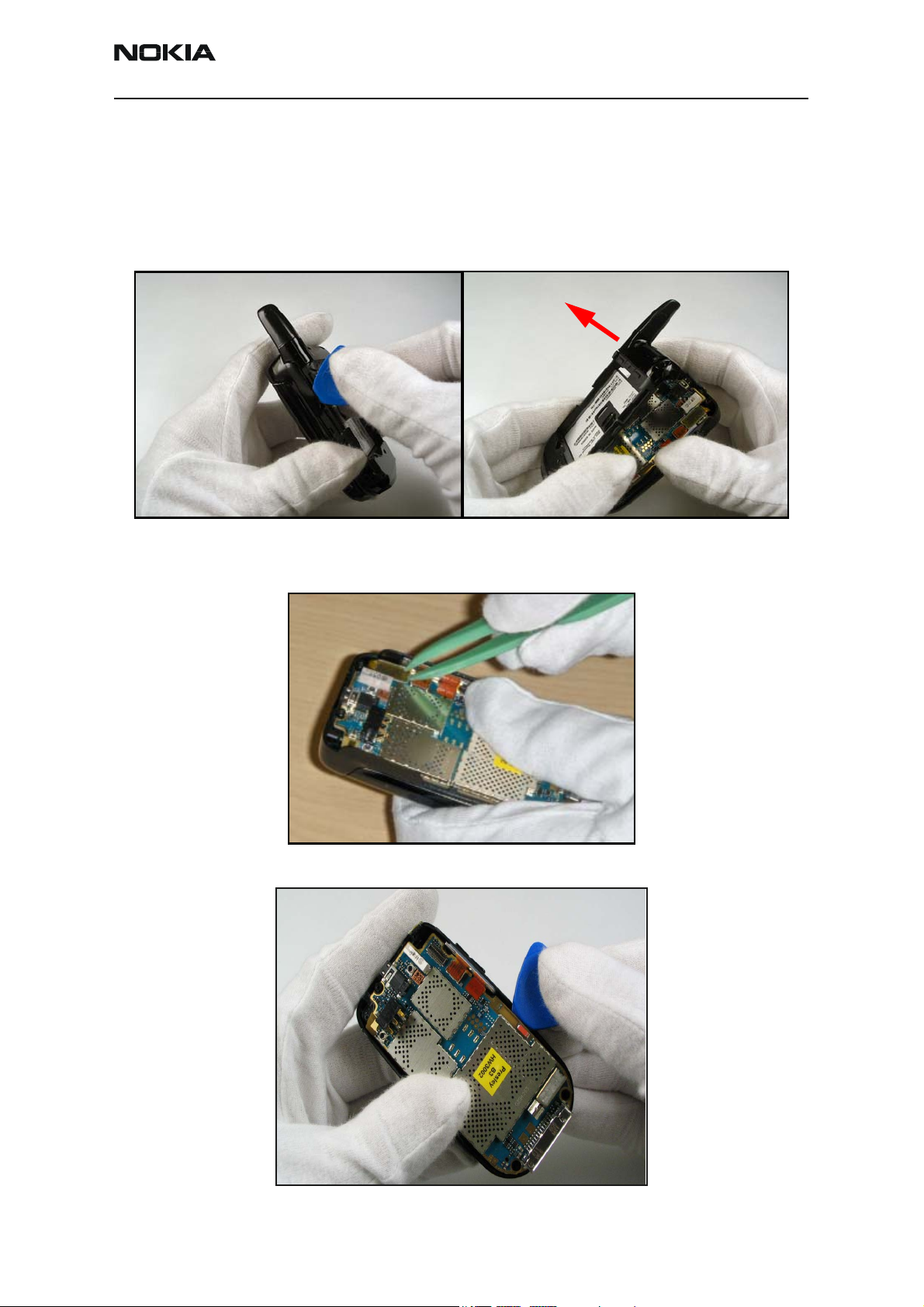
3. Separate the D-cover from the C-cover
Open the grommet that seals the Universal Headphone Jack (UHJ).
Use an SRT-6 or an SS-93 tool to unsnap the D-cover from the handset.
Lift the D-cover straight off of the assembly, and set the cover aside.
1
4. Remove the Main PWB
Disconnect the main flex connector.
2
Release the two plastic retention tabs.
Issue 2 - February 2007 Company Confidential Page 5
Page 6

2366i (RM-155)
Disassembly Nokia Customer Care
Lift the main PWB and the side key flex assembly from the cover.
5. Remove the Sidekey Switch Assembly
Note: only remove the Sidekey Switch Assembly if it is to be replaced with a new one.
Use the guitar pick to pry up the inside edge of the connectors from the PWB.
Page 6 Company Confidential Issue 2 - February 2007
Page 7

2366i (RM-155)
Nokia Customer Care Disassembly
6. Remove the UHJ Cover
Remove the UHJ Cover from the D-cover. If the UHJ cover is damaged, replace it;
otherwise, set the UHJ cover aside.
7. Remove the Microphone Module
Use plastic tweezers to remove the microphone module from the D-cover.
Issue 2 - February 2007 Company Confidential Page 7
Page 8

2366i (RM-155)
Disassembly Nokia Customer Care
8. Remove the DC Jack
Use the CA-44 tool to lift the jack and remove it.
9. Remove the Antenna.
Remove the RF grommet.
Use plastic tweezers to lift the retaining latch. Do not cause damage to the contacts.
Page 8 Company Confidential Issue 2 - February 2007
Page 9

2366i (RM-155)
Nokia Customer Care Disassembly
Remove the antenna.
10. Remove the Keymat and the Sidekey
Press the keymat up, and remove it from the C-cover.
Use plastic tweezers to lift out the sidekey. Make note of the orientation of the sidekey
for later installation.
Issue 2 - February 2007 Company Confidential Page 9
Page 10

2366i (RM-155)
Disassembly Nokia Customer Care
11. Disengage the Hinge Assembly
Hold the assembly as shown.
Flex the C-cover to release the right hinge.
Note: do not separate the LEFT hinge first, as damage to the main flex cable may
occur.
Disengage the left hinge.
Note: Do not separate the left hinge further, yet, as damage to the main flex cable
may occur.
Use plastic tweezers to open the flip damper and allow the main flex cable to slide freely
through.
Page 10 Company Confidential Issue 2 - February 2007
Page 11

2366i (RM-155)
Nokia Customer Care Disassembly
Lift the C-cover away and set it aside.
12. Separate the A-cover from the B-cover
Use the guitar pic to unlock the clasps. Start near the hinge and work counter-clockwise
around the assembly.
Note: Several tabs require release before the A-cover can be removed. Ensure that you
do not damage the tabs with excessive force.
Issue 2 - February 2007 Company Confidential Page 11
Page 12

2366i (RM-155)
Disassembly Nokia Customer Care
13. Remove the Flex Connections
Use the plastic tweezers and guitar pick to unattach the flex connections.
14. Disassemble the Upper UI Assembly
Remove the 4 #6 Torx screws in the order shown.
3
4
Disengage the upper UI assembly from the B-cover.
Note: do not separate the assembly from the B-cover yet, to avoid damage to the
main flex cable.
1
2
Page 12 Company Confidential Issue 2 - February 2007
Page 13

2366i (RM-155)
Nokia Customer Care Disassembly
Use plastic tweezers to guide the main flex cable out of the slot in the B-cover.
Separate the Upper UI Assembly from the B-cover and set the cover aside.
15. Disassemble the External Display
Use an SRT-6 tool to disconnect the external LCD display connector. Hold the flex down
and pry from the bottom edge.
Issue 2 - February 2007 Company Confidential Page 13
Page 14

2366i (RM-155)
Disassembly Nokia Customer Care
Turn the metal mounting frame over to reveal the back of the external LCD display. Use
an SRT-6 tool to lift the display clear of the frame.
Remove the external LCD display, pulling the flex connector through the access hole.
16. Remove the Earpiece
Use tweezers or a dental pick to break the adhesive seal and lift out the earpiece.
Note: Do not bend or damage the contacts.
The disassembly procedure is complete.
Page 14 Company Confidential Issue 2 - February 2007
 Loading...