

Page 1

Nokia Customer Care
6275/6275i (RM-154)
Mobile Terminals
Disassembly
Issue 1 - September 2006 Company Confidential
Page 2

6275/6275i (RM-154)
Disassembly Nokia Customer Care
Contents Page
Safety Information......................................................................................................................................... 3
ESD Protection .............................................................................................................................................3
Disassembly Instructions.............................................................................................................................. 4
1. Remove the Battery Cover ...................................................................................................................4
2. Remove the Antenna Cover .................................................................................................................5
3. Remove the A-Cover and Keymat ......................................................................................................5
5. Remove the UI Module ..........................................................................................................................7
6. Remove the PWB and LCD Module ....................................................................................................8
7. Remove the IHF Assembly ....................................................................................................................9
8. Remove the DC Jack, Microphone, and Battery Floor ................................................................10
9. Remove the Volume/Zoom Key and Camera Key .........................................................................11
10. Remove the Camera Module ...........................................................................................................12
Page 2 Company Confidential Issue 1 - September 2006
Page 3
6275/6275i (RM-154)
Nokia Customer Care Disassembly
Safety Information
Adhere to the following guidelines when assembling and disassembling the mobile
terminal.
•QUALIFIED SERVICE
Only qualified personnel may install or repair mobile terminal equipment.
• ACCESSORIES AND BATTERIES
Use only approved accessories and batteries. Do not connect incompatible
products.
• CONNECTING TO OTHER DEVICES
When connecting to any other device, read its user’s guide for detailed safety
instructions. Do not connect incompatible products.
ESD Protection
Nokia requires that mobile terminal repair centers have sufficient ESD protection against
static electricity when servicing mobile terminals. Use the following guidelines:
• A mobile terminal that is ready for use can be handled normally without ESD
protection. The battery can be replaced in normal conditions of use.
• Use ESD protection when replacing a color cover, except for the mobile terminal
covers which can be replaced by the customer.
• All electronic parts of the mobile terminal, including the display, are susceptible
to ESD. Resistors also can be damaged by static electricity discharge.
• All ESD-sensitive parts must be packed in metallized protective bags during
shipping and handling outside any ESD Protected Area (EPA).
• Every repair action involving opening the mobile terminal or handling the mobile
terminal components must be done under ESD protection.
• ESD-protected spare part packages MUST NOT be opened/closed outside an EPA.
For more detailed information about ESD protection and EPAs, contact your local Nokia
Customer Care representative.
Issue 1 - September 2006 Company Confidential Page 3
Page 4
6275/6275i (RM-154)
Disassembly Nokia Customer Care
Disassembly Instructions
Use the following steps to disassemble the mobile terminal.
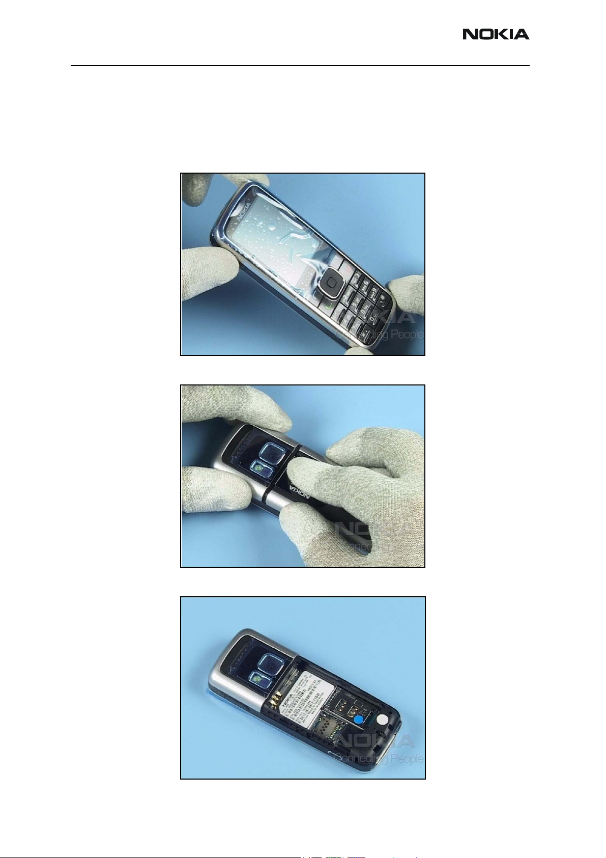
1. Remove the Battery Cover
Cover the windows with a protective plastic film.
Press down on the B-cover while sliding it away from the body of the mobile terminal.
If installed, remove the battery.
Page 4 Company Confidential Issue 1 - September 2006
Page 5
6275/6275i (RM-154)
Nokia Customer Care Disassembly
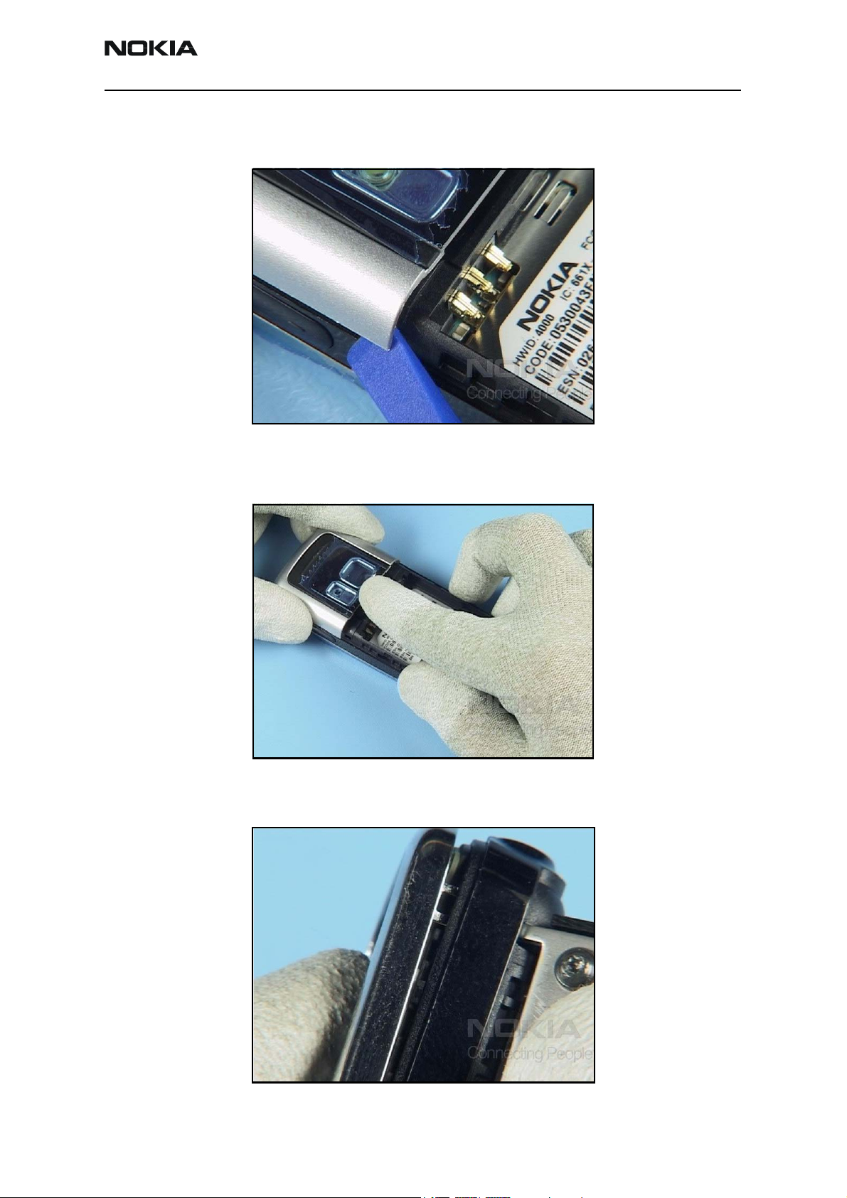
2. Remove the Antenna Cover
Carefully unlock the antenna cover clips on both sides.
Work your way around the assembly while loosening the cover. Be careful of the header
cap and retaining snaps along either side and at top. After the cover pops loose from the
assembly, slide the antenna cover off.
3. Remove the A-Cover and Keymat
Push down on the keymat while opening the clips of the A-cover with the SS-106 tool.
Issue 1 - September 2006 Company Confidential Page 5
Page 6

6275/6275i (RM-154)
Disassembly Nokia Customer Care
Press/hold your thumb against the keypad while maneuvering the removal tool. Lift the
tool until the A-cover clips detach from the D-cover. After the A-cover prongs release
from the D-cover, separate the A-cover from the D-cover.
Remove the keymat.
Apply a protective film to the inner side window.
Page 6 Company Confidential Issue 1 - September 2006
Page 7

6275/6275i (RM-154)
Nokia Customer Care Disassembly
5. Remove the UI Module
In the order shown, remove the 6-Torx retaining screws.
Unlock the metal clip holding the LCD connector and lift it away from the assembly.
Use the SS-93 tool to detach the flex connector.
Issue 1 - September 2006 Company Confidential Page 7
Page 8

6275/6275i (RM-154)
Disassembly Nokia Customer Care
Use the SS-93 tool to unlock the plastic snaps on both sides of the C-cover assembly.
Lift up and remove the assembly.
6. Remove the PWB and LCD Module
Lift the PWB up from the assembly.
Page 8 Company Confidential Issue 1 - September 2006
Page 9

6275/6275i (RM-154)
Nokia Customer Care Disassembly
Carefully pry the LCD module from the assembly.
Carefully slide the assembly into the alignment shown below.
7. Remove the IHF Assembly
Pry the IHF assembly out. However, be careful not to bend or damage the spring
contacts.
Issue 1 - September 2006 Company Confidential Page 9
Page 10

6275/6275i (RM-154)
Disassembly Nokia Customer Care
Use the top of the SS-93 tool to pry the earpiece out.
Carefully release the clips of the D-cover. These clips are very delicate and can break
easily. This enables you to release the flash module.
8. Remove the DC Jack, Microphone, and Battery Floor
Use the DC plug to remove the DC jack.
Page 10 Company Confidential Issue 1 - September 2006
Page 11

6275/6275i (RM-154)
Nokia Customer Care Disassembly
Use the tweezers to remove the microphone.
Unlock the metal latches of the battery floor.
9. Remove the Volume/Zoom Key and Camera Key
Use the tweezers to release and remove the volume and zoom key.
Issue 1 - September 2006 Company Confidential Page 11
Page 12

6275/6275i (RM-154)
Disassembly Nokia Customer Care
Use the tweezers to release and remove the camera key.
10. Remove the Camera Module
Use the soldering jig or at least the C-cover as support when replacing the camera
module.
Use the SS-45 camera removal tool to release the clips of the camera module.
Page 12 Company Confidential Issue 1 - September 2006
Page 13

6275/6275i (RM-154)
Nokia Customer Care Disassembly
Vertically lift the camera module out of the assembly.
The disassembly procedure is complete.
Issue 1 - September 2006 Company Confidential Page 13
Page 14

6275/6275i (RM-154)
Disassembly Nokia Customer Care
Page 14 Company Confidential Issue 1 - September 2006
 Loading...