

Page 1

Nokia Customer Care
6275/6275i (RM-154)
Mobile Terminals
Assembly
Issue 1 - September 2006 Company Confidential
Page 2

6275/6275i (RM-154)
Assembly Nokia Customer Care
Contents Page
Safety Information......................................................................................................................................... 3
ESD Protection .............................................................................................................................................3
Assembly Instructions ................................................................................................................................... 4
1. Insert the Camera Module ...................................................................................................................4
2. Insert the Camera Key and Volume/Zoom Key ...............................................................................5
3. Insert the Battery Floor .........................................................................................................................6
5. Insert the Microphone and DC Jack ..................................................................................................6
6. Insert the Flash Module ........................................................................................................................7
7. Insert the IHF Speaker and IHF Module ...........................................................................................7
8. Insert the LCD Module and PWB ........................................................................................................ 8
9. Assemble the UI Module and Keymat ............................................................................................... 9
10. Insert the A-Cover, Antenna Cover, and B-Cover .....................................................................11
Page 2 Company Confidential Issue 1 - September 2006
Page 3
6275/6275i (RM-154)
Nokia Customer Care Assembly
Safety Information
Adhere to the following guidelines when assembling and disassembling the mobile
terminal.
•QUALIFIED SERVICE
Only qualified personnel may install or repair mobile terminal equipment.
• ACCESSORIES AND BATTERIES
Use only approved accessories and batteries. Do not connect incompatible
products.
• CONNECTING TO OTHER DEVICES
When connecting to any other device, read its user’s guide for detailed safety
instructions. Do not connect incompatible products.
ESD Protection
Nokia requires that mobile terminal repair centers have sufficient ESD protection against
static electricity when servicing mobile terminals. Use the following guidelines:
• A mobile terminal that is ready for use can be handled normally without ESD
protection. The battery can be replaced in normal conditions of use.
• Use ESD protection when replacing a color cover, except for the mobile terminal
covers which can be replaced by the customer.
• All electronic parts of the mobile terminal, including the display, are susceptible
to ESD. Resistors also can be damaged by static electricity discharge.
• All ESD-sensitive parts must be packed in metallized protective bags during
shipping and handling outside any ESD Protected Area (EPA).
• Every repair action involving opening the mobile terminal or handling the mobile
terminal components must be done under ESD protection.
• ESD-protected spare part packages MUST NOT be opened/closed outside an EPA.
For more detailed information about ESD protection and EPAs, contact your local Nokia
Customer Care representative.
Issue 1 - September 2006 Company Confidential Page 3
Page 4
6275/6275i (RM-154)
Assembly Nokia Customer Care
Assembly Instructions
Use the following steps to assemble the mobile terminal.
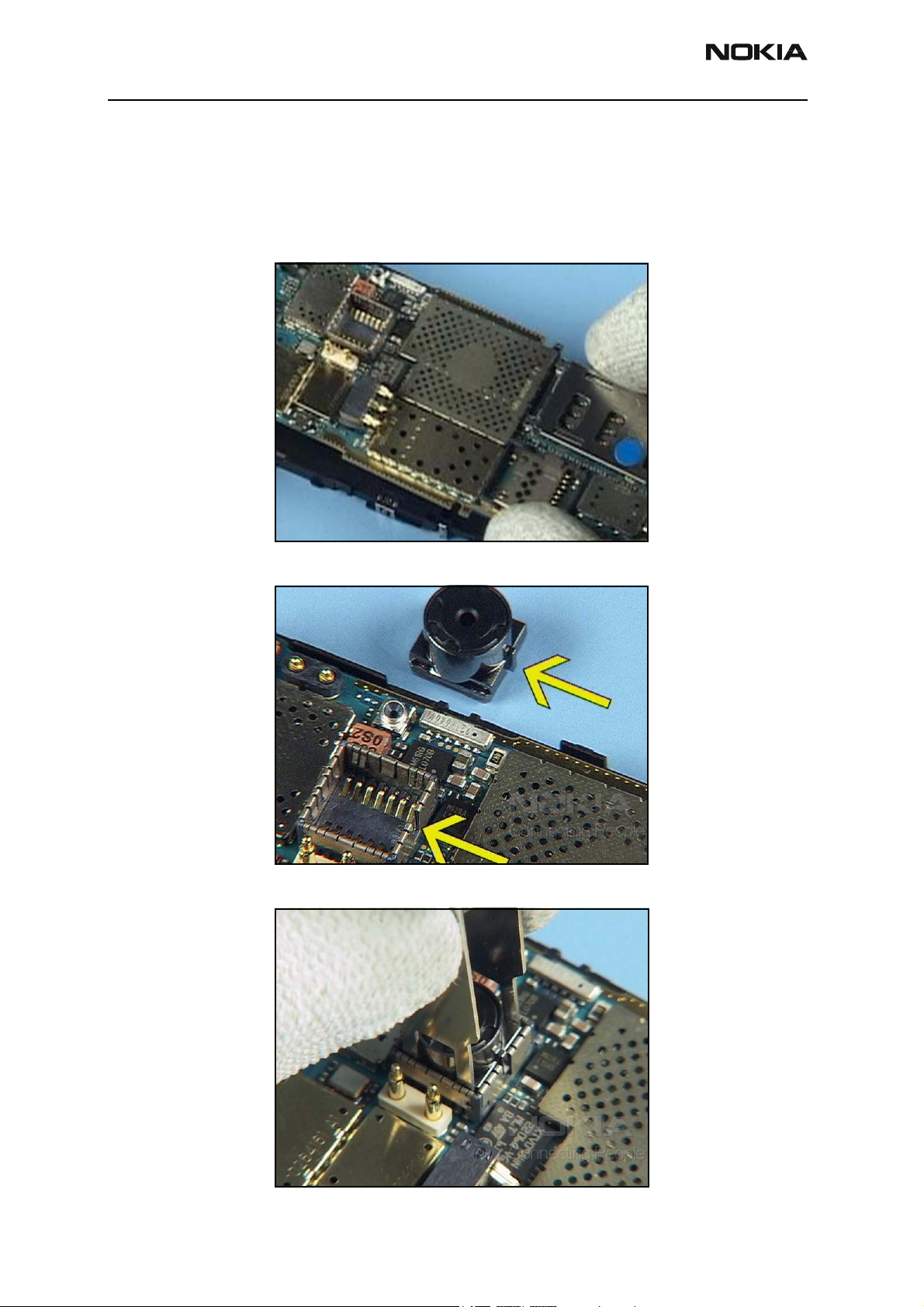
1. Insert the Camera Module
Use a soldering jig or the C-cover assembly as support to replace the camera module.
Ensure that the notch on the camera module aligns properly with the slot on the PWB.
Insert the camera module.
Page 4 Company Confidential Issue 1 - September 2006
Page 5

6275/6275i (RM-154)
Nokia Customer Care Assembly
Ensure that the camera fastens in place evenly.
2. Insert the Camera Key and Volume/Zoom Key
Use tweezers to insert the camera key.
Use tweezers to insert the volume and zoom key.
Issue 1 - September 2006 Company Confidential Page 5
Page 6

6275/6275i (RM-154)
Assembly Nokia Customer Care
3. Insert the Battery Floor
Insert the battery floor, and click all of the snaps into their latches.
5. Insert the Microphone and DC Jack
Insert the microphone, and lock it into the assembly.
Page 6 Company Confidential Issue 1 - September 2006
Page 7

6275/6275i (RM-154)
Nokia Customer Care Assembly
Use the DC plug to insert the DC jack into the assembly.
6. Insert the Flash Module
Insert the flash module. Ensure that the plastic clips are click into their places correctly.
7. Insert the IHF Speaker and IHF Module
Use the tweezers to insert the earpiece into the IHF module.
Issue 1 - September 2006 Company Confidential Page 7
Page 8

6275/6275i (RM-154)
Assembly Nokia Customer Care
Insert the IHF module into the D-cover. Ensure that all the snaps click into place.
8. Insert the LCD Module and PWB
Replace the adhesive on the assembly.
Align the guide tabs on the LCD module with the grooves in the assembly.
Page 8 Company Confidential Issue 1 - September 2006
Page 9

6275/6275i (RM-154)
Nokia Customer Care Assembly
Assemble the PWB onto the D-cover.
Carefully align and press down on the flex connector until it snaps to the PWB.
9. Assemble the UI Module and Keymat
Align the metal clips on the UI module, and insert it into the assembly.
Issue 1 - September 2006 Company Confidential Page 9
Page 10

6275/6275i (RM-154)
Assembly Nokia Customer Care
Insert the six screws.
Set the correct torque. To prevent damage to the plastic threads, turn the screws left
first, then tighten them.
Apply the correct torque in the order shown.
Page 10 Company Confidential Issue 1 - September 2006
Page 11

6275/6275i (RM-154)
Nokia Customer Care Assembly
Remove the protective film from the inside window.
Insert the keymat into the A-cover.
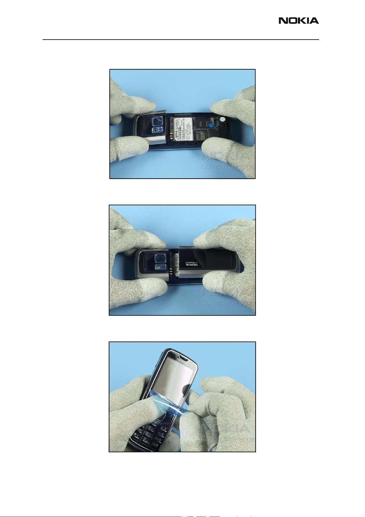
10. Insert the A-Cover, Antenna Cover, and B-Cover
Starting at the top, align the A-cover with the snaps. Carefully apply pressure and lock
the A-cover to the assembly.
Issue 1 - September 2006 Company Confidential Page 11
Page 12
6275/6275i (RM-154)
Assembly Nokia Customer Care
Starting at the top, align the antenna cover into the grooves of the assembly. Carefully
apply pressure and snap into place.
Align the B-cover with the guides on the assembly. Press down and slide the B-cover
towards the top of the assembly until it clicks into place.
Remove the protective film, and ensure that the window is void of scratches, smudges, or
dirt.
The assembly procedure is complete.
Page 12 Company Confidential Issue 1 - September 2006
 Loading...