

Page 1

Nokia Customer Care
6275/6275i (RM-154)
Mobile Terminal
Baseband Description and
Troubleshooting
Issue 1 - September 2006 Company Confidential ©2006 Nokia Corporation
Page 2

6275/6275i (RM-154)
Baseband Description and Troubleshooting Nokia Customer Care
Contents Page
Introduction ..................................................................................................................................................... 4
Baseband Components.................................................................................................................................. 5
Power-Up Sequence ...................................................................................................................................7
FM Radio ........................................................................................................................................................... 9
FM Radio Test ...............................................................................................................................................9
FM Radio Troubleshooting ........................................................................................................................9
FM Radio Control - Phoenix Interface ................................................................................................10
GPS................................................................................................................................................................... 12
GPS Troubleshooting ................................................................................................................................13
GPS Phoenix Interface ..............................................................................................................................14
Bluetooth ....................................................................................................................................................... 15
Bluetooth Troubleshooting .....................................................................................................................15
Bluetooth Phoenix .....................................................................................................................................16
SIM Card......................................................................................................................................................... 17
SIM Card Troubleshooting ......................................................................................................................17
SIM Card Phoenix Interface ....................................................................................................................19
Camera............................................................................................................................................................ 20
Camera Troubleshooting ..........................................................................................................................20
Camera Phoenix Interface .......................................................................................................................21
MicroSD.......................................................................................................................................................... 22
IR ...................................................................................................................................................................... 23
IR Troubleshooting ....................................................................................................................................23
IR Phoenix Interface .................................................................................................................................24
USB .................................................................................................................................................................. 25
USB Troubleshooting ................................................................................................................................25
USB Phoenix Interface .............................................................................................................................26
Display ............................................................................................................................................................ 27
Display Troubleshooting .......................................................................................................
Display and Keypad Backlight Troubleshooting ................................................................................28
Display Phoenix Interface .......................................................................................................................29
Keypad Backlight Troubleshooting .......................................................................................................29
Audio............................................................................................................................................................... 31
Audio Troubleshooting .............................................................................................................................31
Audio Phoenix Interface ..........................................................................................................................32
System Connector........................................................................................................................................ 33
Accessory Detection .................................................................................................................................34
Flash Programming ..................................................................................................................................... 35
Flashing Tool ...............................................................................................................................................35
Flashing Phoenix Interface........................................................................................................................ 35
Battery (Lynx) Interface Circuit............................................................................................................... 37
Charging......................................................................................................................................................... 38
Alignment ...................................................................................................................................................... 39
AMS Baseband Calibration......................................................................................................
Final UI Check............................................................................................................................................... 41
Problems During Flash and Alignment .................................................................................................. 42
No Communication - Flash .....................................................................................................................42
No Communication - Alignment ...........................................................................................................42
...................27
................ 40
Page 2 Company Confidential Issue 1 - September 2006
Page 3

6275/6275i (RM-154)
Nokia Customer Care Baseband Description and Troubleshooting
Failed Self Test/Calibration .....................................................................................................................42
Other Potential Problems .......................................................................................................................... 43
Mobile Terminal Does Not Power Up ...................................................................................................43
Shutdown after 32 Seconds ...................................................................................................................43
No Audio ......................................................................................................................................................43
Keypad Malfunction .................................................................................................................................43
No LCD Display ...........................................................................................................................................43
Phoenix Tools................................................................................................................................................ 44
Local Mode ..................................................................................................................................................44
Reading the Mobile Terminal .................................................................................................................45
Running the Self Test ...............................................................................................................................47
Checking the Baseband Regulator/General I/O parameters ..........................................................48
Flashing the Mobile Terminal .................................................................................................................49
Flashing - EZ-Flash................................................................................................................................ 49
Reference ....................................................................................................................................................... 50
Signal References ......................................................................................................................................50
Issue 1 - September 2006 Company Confidential Page 3
Page 4

6275/6275i (RM-154)
Baseband Description and Troubleshooting Nokia Customer Care
Introduction
The 6275/6275i baseband module is a tri-mode, code division multiple access (CDMA),
dual-band engine and is based on the DCT4.5 standard. The baseband engine includes
two major Application Specific Integrated Circuits (ASICs):
• D2200 — Universal Energy Management Enhanced Integrated Circuit (UEMEK IC),
which includes the audio circuits, charge control, and voltage regulators
• D2800 — Main processor, which includes system logic for CDMA, two Digital
Signal Processors (DSPs), the Main Control Unit (MCU), and the memory.
The BL-6C Li-ion battery is used as the main power source and has a nominal capacity of
1150 mAh.
Page 4 Company Confidential Issue 1 - September 2006
Page 5
6275/6275i (RM-154)
Nokia Customer Care Baseband Description and Troubleshooting
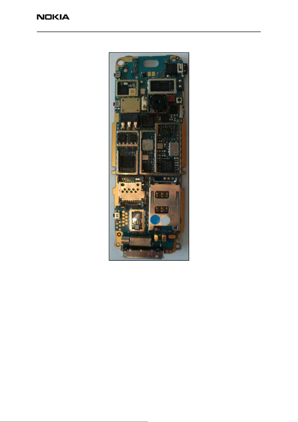
Baseband Components
Figure 1: PWB - bottom side
Issue 1 - September 2006 Company Confidential Page 5
Page 6
6275/6275i (RM-154)
Baseband Description and Troubleshooting Nokia Customer Care
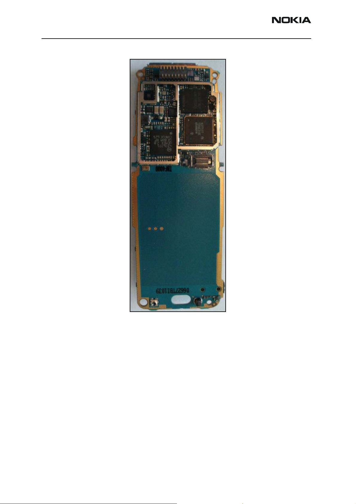
Figure 2: PWB - top side
Page 6 Company Confidential Issue 1 - September 2006
Page 7
6275/6275i (RM-154)
Nokia Customer Care Baseband Description and Troubleshooting
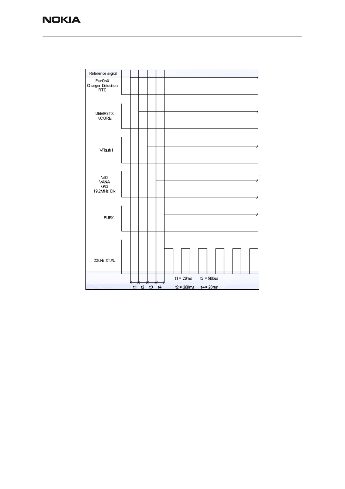
Reset mode is entered and the watchdog
starts. VCORE is enabled, and provides
power to the D2800.
End of settling time (only if Vbat >Vcoff+)
VFlash1 regulator is enabled.
VR3, VANA, VIO are enabled. PURX is held
low.
D2800, MCU, and DSP are reset; PURX
releases.
Figure 3:
Issue 1 - September 2006 Company Confidential Page 7
Page 8

6275/6275i (RM-154)
Baseband Description and Troubleshooting Nokia Customer Care
Figure 4: flash programming
Page 8 Company Confidential Issue 1 - September 2006
Page 9
6275/6275i (RM-154)
Nokia Customer Care Baseband Description and Troubleshooting
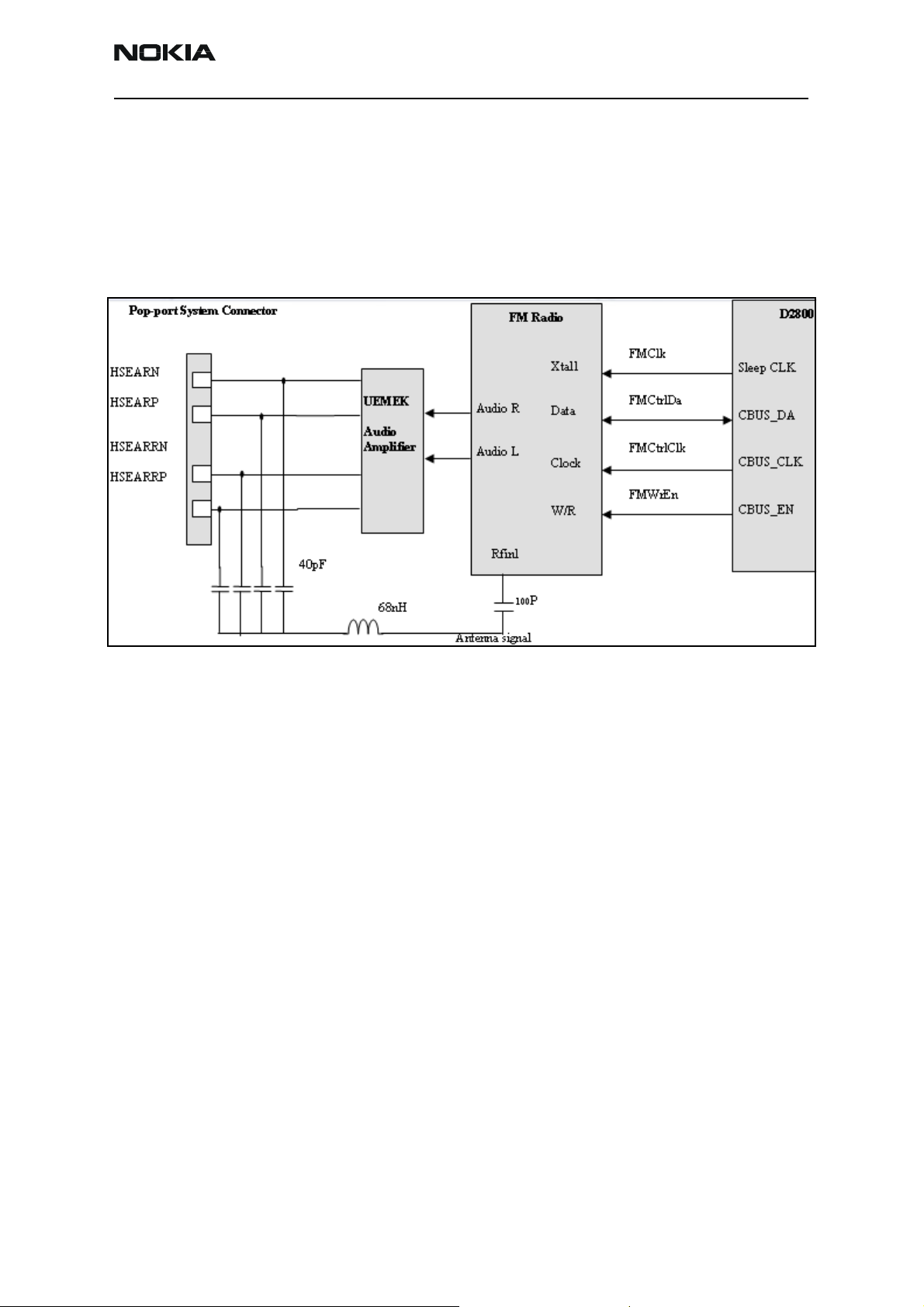
FM Radio
The D2800 turns on the FM radio and sets the frequency, using the CBUS serial interface
as the communication channel. The high frequency FM radio signal comes in through the
RFIN1 pin to the FM radio integrated circuit. The RF signal is demodulated, and the
resulting audio signal is sent to the UEMEK for amplification. The amplified signal is then
delivered to the universal headset jack (UHJ) or to the Pop-port™ connector to drive a
stereo headset.
Figure 5: FM radio, audio, antenna, and digital interface connections
FM Radio Test
To hear the FM radio, first connect a headset to either the Pop-port or the UHJ port. The
headset wiring functions as an FM radio antenna. If the Pop-port connector is in use by
the Phoenix service program, connect the headset to UHJ port to control the FM radio.
If you connect a headset (such as HDS-3) to the Pop-port connector, you cannot control
the mobile terminal because you already occupied the Pop-port connection port. If you
connect a headset, you have to have jumper wires on production test points (Fbus/Tx
RX,GND).
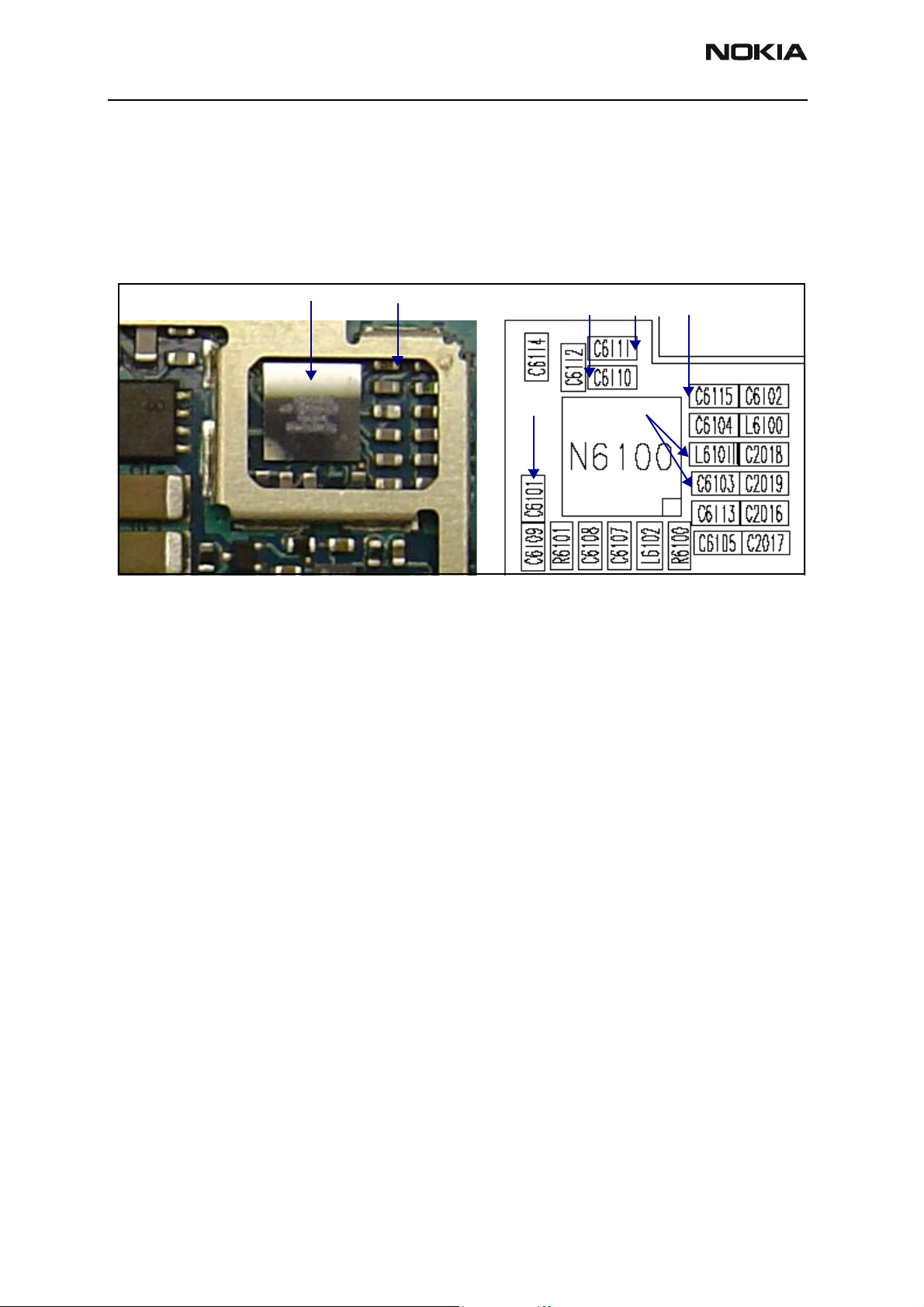
FM Radio Troubleshooting
When troubleshooting the FM radio, make these common checks (see Figure 6):
• Power supplies VIO and VANA
• Sleep_CLK
• FMANT input to FM radio
• CBUS interface by probing CBUS_EN and looking for activity
• Output of FM radio on VAFR and VAFL; it should be a audio signal with a 800mV
DC-offset.
Issue 1 - September 2006 Company Confidential Page 9
Page 10
6275/6275i (RM-154)
Baseband Description and Troubleshooting Nokia Customer Care
• If the audio signal is not correct (with offset of 800 mV DC), then check the FM
radio integrated circuit for shorts, voids, and misalignments.
• If the audio signal is correct (with offset of 800 mV DC), then check the UEMEK
for shorts, voids, and misalignments.
• If the UEMEK and FM radio integrated circuits are okay, check the system
connector.
FM chip; check solder Ground
VAFL
VAFR
VIO (1.8V) FMANT
VANA (2.8V)
Figure 6: FM radio integrated circuit
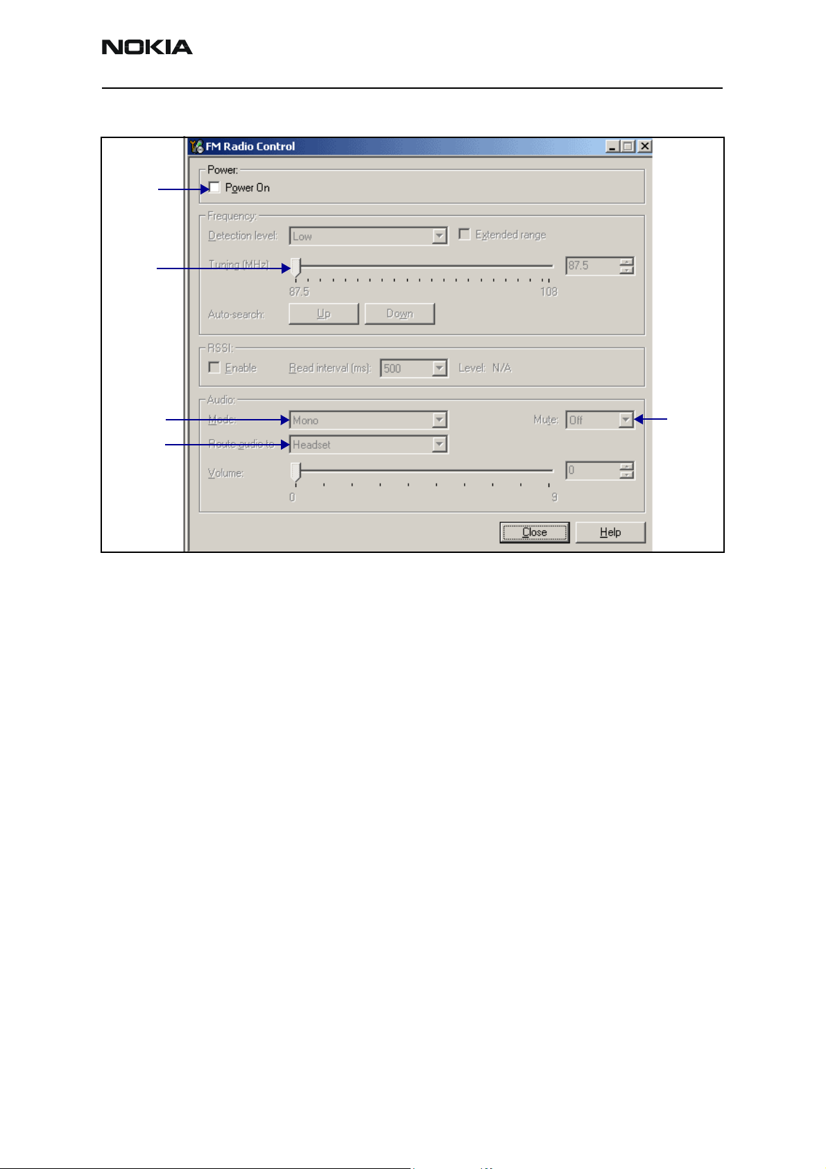
FM Radio Control - Phoenix Interface
Use the Phoenix interface to perform the following tasks:
1. Connect a headset to the UHJ
2. Turn on the FM radio using Phoenix.
Page 10 Company Confidential Issue 1 - September 2006
Page 11
6275/6275i (RM-154)
Nokia Customer Care Baseband Description and Troubleshooting
3. Set the frequency and volume.
Power on
Frequency
Frequency
control
control
Mono/stereo
control
Headset/IHF
control
Mute on/
off control
Figure 7: Phoenix FM Radio control panel
4. Observe that an audio signal is heard in the headset.
5. If FM Radio is working, retest on FinalUI.
Issue 1 - September 2006 Company Confidential Page 11
Page 12
6275/6275i (RM-154)
Baseband Description and Troubleshooting Nokia Customer Care
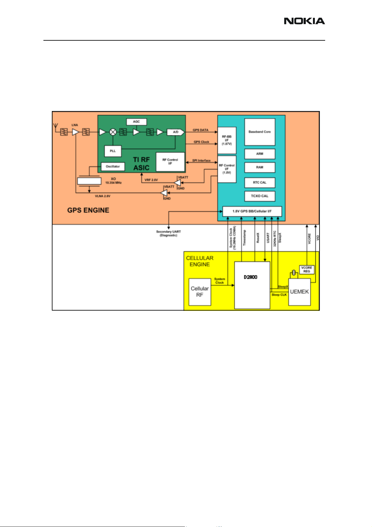
GPS
The GPS turns on by using Vcore and VIO from the UEMEK. The GPS communicates with
the D2800 using the UART interface and turns on the GPS engine’s BB integrated circuit
and RF integrated circuit. They synchronize with the mobile terminal using the 19.2 Mhz
clock. The mobile terminal locates the closest satellite and downloads the location
coordinates to send them to the emergency desk.
Figure 8: GPS block diagram
The GPS baseband module performs the following:
• Accepts the GPS raw data from the front end
• Processes the raw data to provide the CE with location information (2 CPUs)
• Accepts commands from the CE
• Manages modes (sleep, idle, etc.)
• Issues RF control commands
• Manages GPS configuration
• Provides power for the FPS RF
Page 12 Company Confidential Issue 1 - September 2006
Page 13
6275/6275i (RM-154)
Nokia Customer Care Baseband Description and Troubleshooting
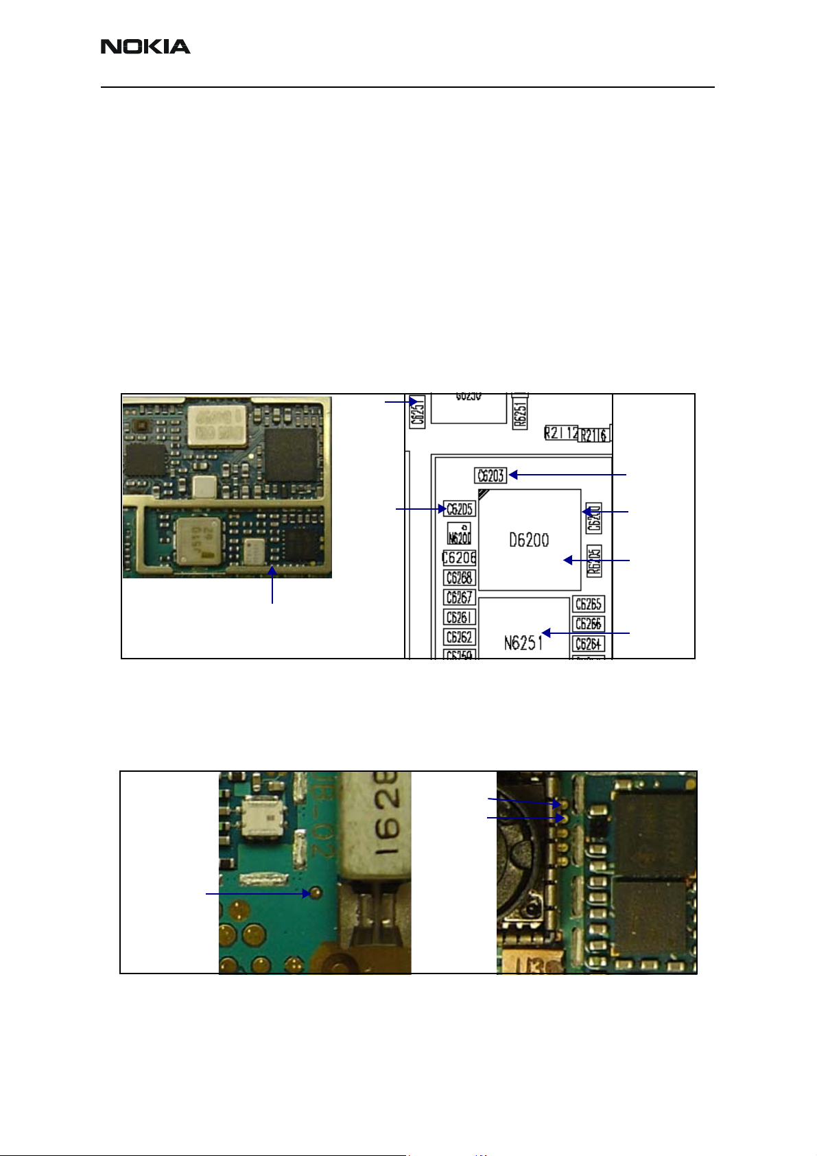
GPS Troubleshooting
Check the following connections and signals (see Figure 9):
• Power source Vcore and VIO
• CLK19M2_GPS = 19.2 Mhz
• VRF is enabled
• VRF_GPS =2.78 V dc
• GPS clock = 16.384 Mhz
• Use Phoenix to run Test Mode 1
•USART activity
• GPS antenna
GPS clock
VRF GPS
CLK19M2_GPS
Figure 9: RF and BB GPS integrated circuits (ICs)
•GPS_EN_RESET (1.8V)
• GPS_SLEEPCLK (32.768kHz)
• GPS_SLEEPX
VIO (1.8V)
VCore (1.35V/
1.05V)
BB GPS
RF GPS
GPS_EN_RESET
GPS_SLEEPX
GPS _SLEEPCLK
Figure 10: Additional GPS components
Issue 1 - September 2006 Company Confidential Page 13
Page 14
6275/6275i (RM-154)
Baseband Description and Troubleshooting Nokia Customer Care
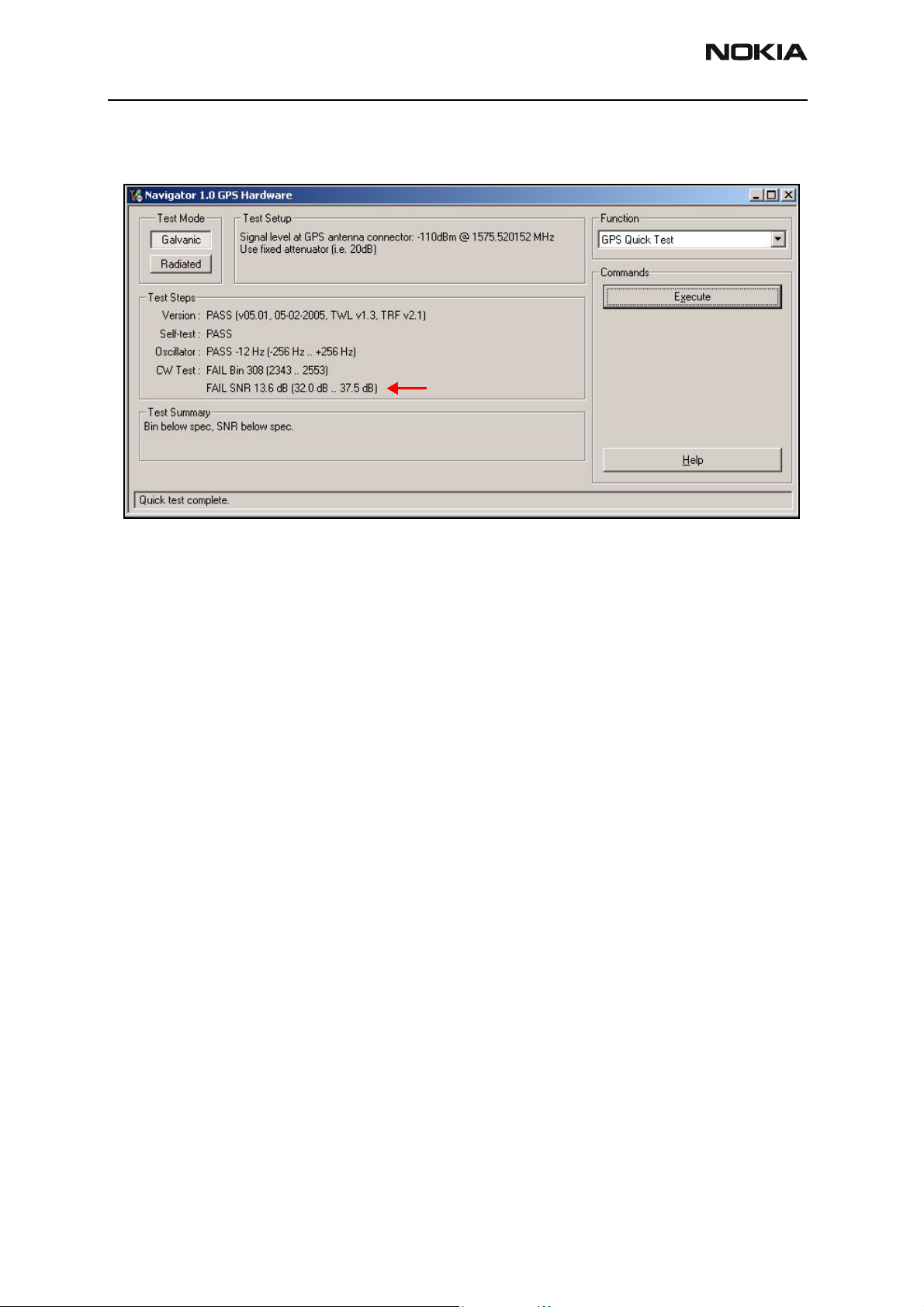
GPS Phoenix Interface
Run the GPS Quick Test in Phoenix to check the GPS BB.
CW Test fails unless CW Tone is
injected into the GPS RF Connector
Figure 11: Phoenix GPS Quick Test option
Page 14 Company Confidential Issue 1 - September 2006
Page 15
6275/6275i (RM-154)
Nokia Customer Care Baseband Description and Troubleshooting
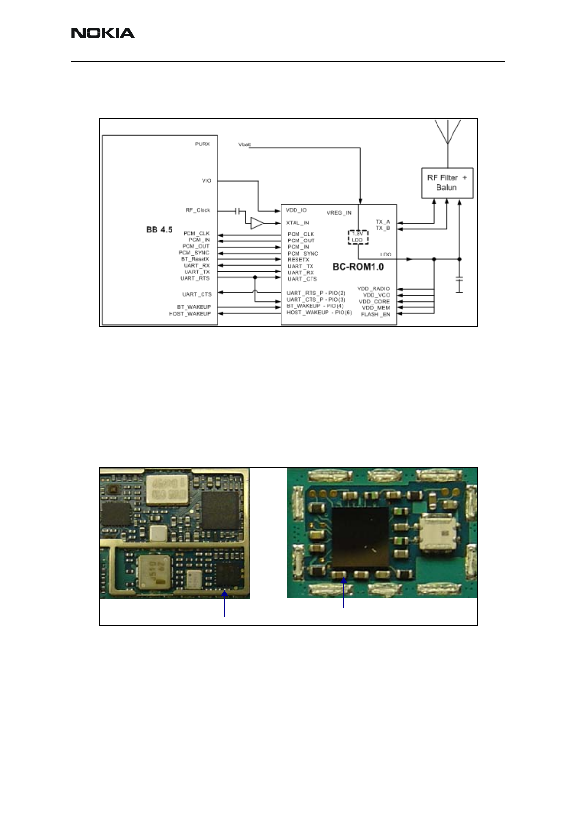
Bluetooth
The Bluetooth radio is shown in the following functional diagram:
Bluetooth Troubleshooting
Before probing, perform a visual inspection of all components and then check the
following:
• Power supply, VIO
• Soldering
• CLK19M2_BT at the UHF synthesizer
CLK19M2_BT
Figure 12: Bluetooth diagram
CLK19M2_GPS
Figure 13: Bluetooth troubleshooting test points
Issue 1 - September 2006 Company Confidential Page 15
Page 16

6275/6275i (RM-154)
Baseband Description and Troubleshooting Nokia Customer Care
Bluetooth Phoenix
On the Bluetooth Locals dialog box, click Run to execute the self test for baseband
communication.
Figure 14: Bluetooth Locals dialog box
Page 16 Company Confidential Issue 1 - September 2006
Page 17

6275/6275i (RM-154)
Nokia Customer Care Baseband Description and Troubleshooting
SIM Card
The 6275/6275i supports two types of SIM cards that work at 1.8 V and 3.0 V dc. When
the mobile terminal is switched on with a SIM card, the D2800 sends a 1.8 V signal to
the SIM card and waits for the SIM card’s response and identification. If there is no
answer from the SIM card, the mobile terminal sends another signal at 1.8 V. However,
the UEMEK then acts as a level shifter and raises the second signal to 3.0 V. If there is
still no response, the mobile terminal does not allow access and displays a prompt to
insert a SIM card. If there is a response, the mobile terminal powers up.
SIM Card Troubleshooting
Use the following steps to troubleshoot the SIM card:
1. Check VSim for a value of either 1.8 V or 3.0 V. The VSim comes from the UEMEK
and goes through the SIM ESD protection integrated circuit. Check for bad or
damaged solder joints. Replace integrated circuits, if necessary.
Figure 15: SIM card block diagram
Figure 16: VSim check
Issue 1 - September 2006 Company Confidential Page 17
Page 18

6275/6275i (RM-154)
Baseband Description and Troubleshooting Nokia Customer Care
2. Check the detection sequence.
SIM connector
VSIM
SIM_CLK
SIMRSTX
SIM ESD
protection
Figure 17: Detection Sequence
3. Verify communication signals.
SIM_DATA
GND
Figure 18: Communication signals
Page 18 Company Confidential Issue 1 - September 2006
Page 19
6275/6275i (RM-154)
Nokia Customer Care Baseband Description and Troubleshooting
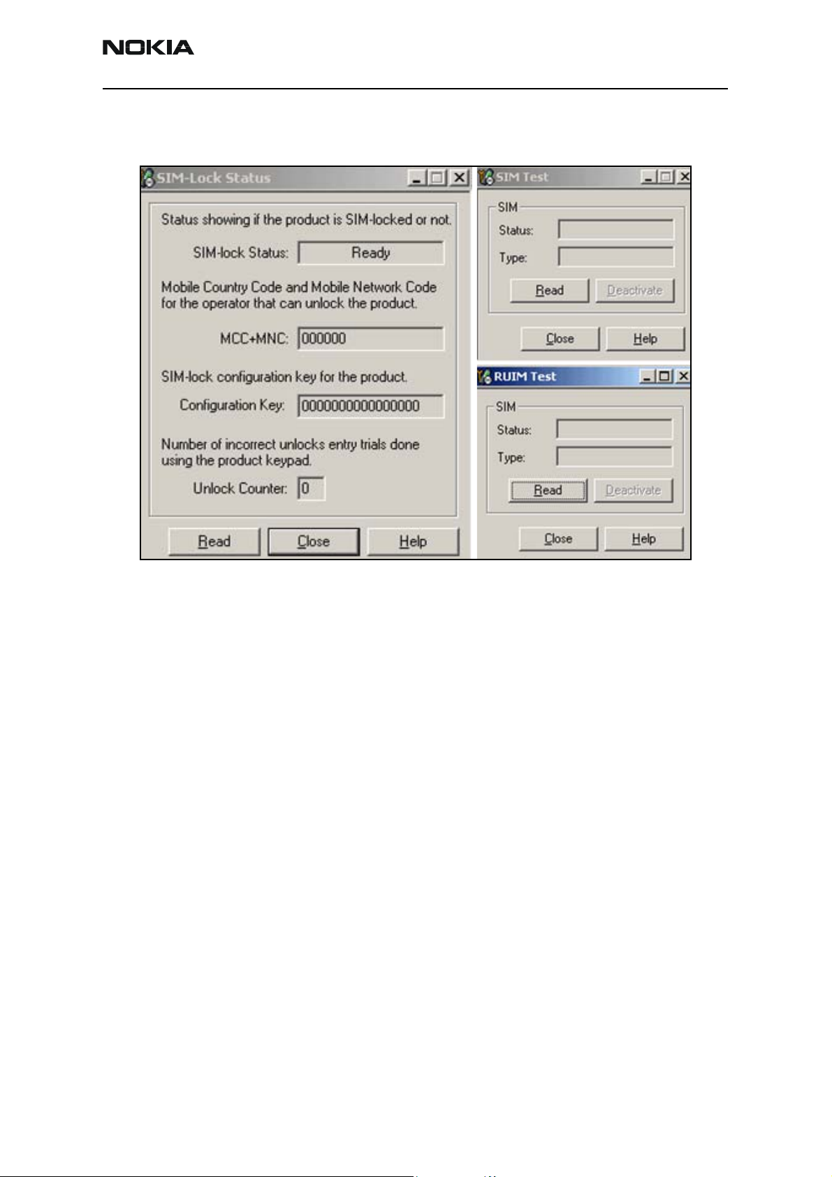
SIM Card Phoenix Interface
Run the SIM-Lock Status test in Phoenix to test a SIM card.
Figure 19: Phoenix SIM/RUIM Test options
Issue 1 - September 2006 Company Confidential Page 19
Page 20

6275/6275i (RM-154)
Baseband Description and Troubleshooting Nokia Customer Care
Camera
When you activate the view finder to take a picture, the D2800 turns the camera on by
turning on GENIO(47) PDN and GENIO(24) 9.6MHz. After the camera initializes, the
D2800 sends control commands through the I2C (GENIO (25 and 26) interface. The
camera takes a picture and sends the raw data back to a separate hardware accelerator
(HWA) device to run the algorithms in the hardware. The HWA performs all tasks to
deliver stills and the viewfinder to the baseband with no further processing required
from the D2800. The D2800 takes the image processed data from the HWA and stores
the image in the Flash Memory or MiniSD.
Camera Troubleshooting
Check the following:
• Power Supply Enable D800_GPIO (47)
• Power Supply V2.8, VDIG and V1.2
• Camera Enable GenIO(27) is High (PDN)
• Camera Clk GenIO(24) (9.6Mhz)
• Control line I2C on GenIO 25 and 26
• CCP data/clk lines from sensor to HWA, then to the D2800
• Camera socket
• D2800 for solder problems; replace if necessary
Raw image data from
sensor to HWA
CCP2/CLKN
CCP2/CLKP
CCP2/DATP
CCP2/DATN
GPIO(24), 9.6MHz
Data/Clk to D2800
CCP1/DATN(1)
CCP1/DATP(0)
Data/Clk to D2800
CCP1/CLKN(2)
CCP1/CLKP(3)
GPIO(47)
V2.8
VDIG 1.8V
V1.2
Figure 20: Camera troubleshooting - part 1
Page 20 Company Confidential Issue 1 - September 2006
Page 21

6275/6275i (RM-154)
Nokia Customer Care Baseband Description and Troubleshooting
GPIO(25)
GPIO(26)
V1.2
VDIG 1.8V
Figure 21: Camera troubleshooting - part 2
Camera Phoenix Interface
Run the Phoenix camera control test to ensure that the camera is working correctly. Click
Test to run the camera test; click Save to save a picture to the PC.
V2.8
Figure 22: Camera Control dialog box
Issue 1 - September 2006 Company Confidential Page 21
Page 22
6275/6275i (RM-154)
Baseband Description and Troubleshooting Nokia Customer Care
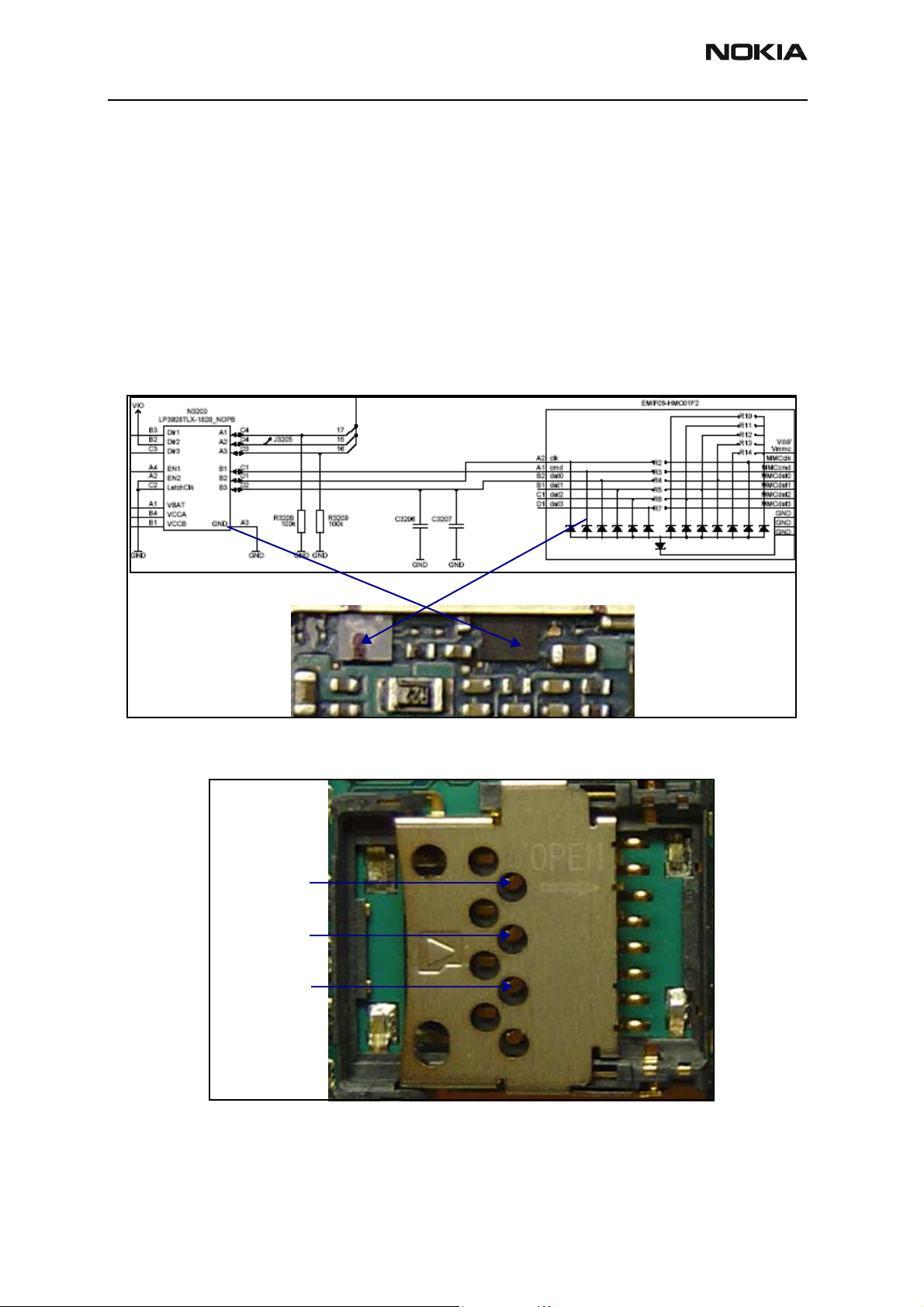
MicroSD
The mobile terminal supports up to 2G byte on a MicroSD card. Check the following:
• Visual inspection of the Level Shifter and ESD ASIP.
• Power supplies VIO, VBAT, and VMSD.
• Micro SD control line activity.
• MMC_CLK, MMC_cmd, MMC_dat0 after the Level Shifter; if not okay, check the
Level Shifter and the D2800.
• MMC_CLK, MMC_cmd, MMC_dat0 after the ESD ASIP; if not okay, replace the
ESD ASIP or check the connector.
MMC_DAT0
MMC_CLK
MMC_CMD
Figure 23: MicroSD troubleshooting points - part 1
Figure 24: MicroSD troubleshooting points - part 2
Page 22 Company Confidential Issue 1 - September 2006
Page 23

6275/6275i (RM-154)
Nokia Customer Care Baseband Description and Troubleshooting
IR
The infrared (IR) circuitry is shown in the flowing functional diagram:
Figure 25: IR Block Diagram
The D2800 enables the IR module by bringing the GPIO (61) signal high. The UEMEK uses
the Vflash1 to provide power supplies to the IR module. Vbat is also used to supply power
to the IR LED. This interface transmits data to and from peripheral equipment through
the IrRX and IrTX line, and transforms serial data to parallel data for the MCU or DSP and
vice versa.
IR Troubleshooting
Use the following illustrations and procedure to troubleshoot the IR system:
Vbat
IR Module
IRTX
IRRX
GPIO(61)
VFlash1
GND
Figure 26: IR Schematics and components
1. Perform a thorough visual inspection on the IR module and capacitors.
2. Check for power supply voltages Vflash1 and VBat.
Issue 1 - September 2006 Company Confidential Page 23
Page 24

6275/6275i (RM-154)
Baseband Description and Troubleshooting Nokia Customer Care
3. If VFlash1 is not okay, check the UEMEK.
4. Check that the logical state of signal GPIO(61) is high.
5. Check for activity on the IRTX and IRRX lines when transmitting or receiving.
6. If GPIO(61) or IRTX and IRRX are not working, check the D2800.
IR Phoenix Interface
Use the IR Test dialog box to troubleshoot in Phoenix.
Figure 27: IR Test dialog box
Page 24 Company Confidential Issue 1 - September 2006
Page 25

6275/6275i (RM-154)
Nokia Customer Care Baseband Description and Troubleshooting
USB
When the mobile terminal is connected to the computer using a DKU-2 or CA-53 data
cable, the PC provides Vbus (5V) to and pull down D+ a, d D – lines. The mobile terminal
responds by pulling the D+ line high. The PC then acknowledges and starts transferring
data at 12 Mbits/s.
USB Troubleshooting
When troubleshooting the USB, refer to Figure 29 and Figure 30 and use the following
procedure to check these points:
1. Connect the mobile terminal to the Phoenix flash station using a DKU-2 or
CA-53 data cable.
2. Use the Windows Device Manager to see if the mobile terminal is recognized as a
USB device. You should see something similar to Figure 29.
• If recognized, there is no hardware fault and you can stop troubleshooting.
• If not recognized, perform a visual inspection on the Pop-port connector,
ESD Protection, NUT integrated circuit, capacitors, and inductors.
Figure 28: USB block diagram
Figure 29: PC Device Manager
Issue 1 - September 2006 Company Confidential Page 25
Page 26
6275/6275i (RM-154)
Baseband Description and Troubleshooting Nokia Customer Care
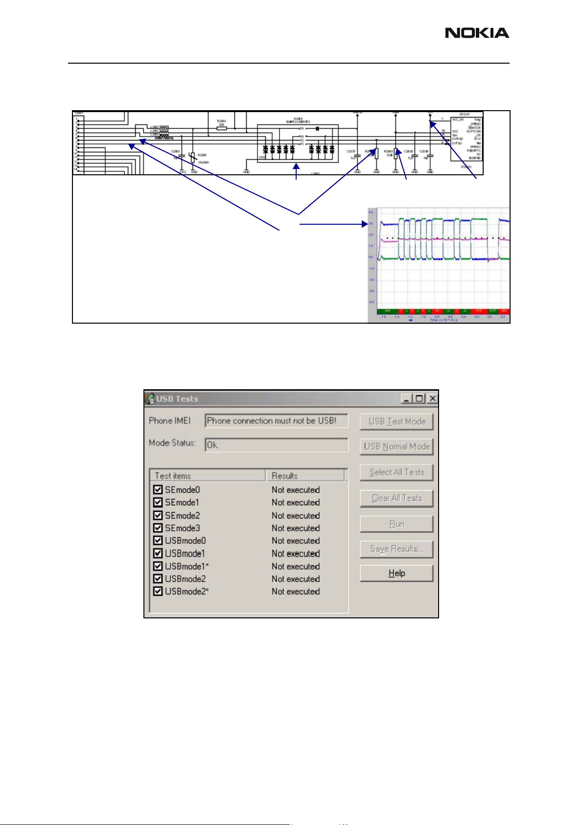
3. Check for activity on the USB D+ and USB D – lines. If there is no activity, inspect
the D2800 under X-ray or change the part.
USB Phoenix Interface
Use the USB Tests dialog box to test the USB.
USB ESD protection USB Vbus (5V)
USB D+
USB D-
Figure 30: USB connections and chart
3.3V
3.3V
VIO
Figure 31: USB Tests dialog box
Page 26 Company Confidential Issue 1 - September 2006
Page 27

6275/6275i (RM-154)
Nokia Customer Care Baseband Description and Troubleshooting
Display
The Nokia 6275/6275i has a large 320x240 QVGA display with 262k colors. This display is
controlled by the D2800 through a parallel interface and powered by UEMEK using VIO
and VFlash1. An ESD ASIP next to the flex connector protects against ESD.
Display Troubleshooting
When troubleshooting the display, refer to Figure 32 and perform the following:
Figure 32: Display test points and chart
1. Check that the display is connected properly and is making good contact with
LCD connector.
2. If there is no display but the backlight is on, check the ESD ASIP for shorts and
cracks.
3. Check the power supply VIO, VFlash1, and VLCD. If they are not correct, check the
UEMEK or VLCD regulator.
4. If there is no backlight and no display, check the board-to-board connector.
5. Check the activity on the LCD test points. If there’s no activity, check or replace
the D2800.
6. Ensure that the DIF Clk is 9.6MHz.
Issue 1 - September 2006 Company Confidential Page 27
Page 28

6275/6275i (RM-154)
Baseband Description and Troubleshooting Nokia Customer Care
Display and Keypad Backlight Troubleshooting
The display backlight uses four LEDs in series powered by an external LED driver.
Vout (~17V)
Rset for internal display
VLED+
LED driver
enable
LED driver
Dlight
Vbat
LED driver
Vout (~17V)
Figure 33: Display Backlight test points
VLED_key
1. Perform a visual inspection of the LCD connector and the LED driver circuitry.
2. If the display backlight does not turn on, check VLED +(~17V) for the main
display.
• If the voltages in the previous step are present, assume the driver is working
properly and the LED inside the display might be bad. Replace the display.
• If not okay, check VLED+ and VLED- (LED return GND) on the display driver
circuitry.
3. If the keypad backlight is off while the display backlight is on, check the B2B
connection and the LED on the keypad.
4. Check that the Klight signal is high (~4V) to turn on the main LCD and keypad
LEDs. If not okay, check the UEMEK.
5. Check that the Vbat(~4V) and Vin(~4V) are present. If not, check the power
supply connection.
Page 28 Company Confidential Issue 1 - September 2006
Page 29
6275/6275i (RM-154)
Nokia Customer Care Baseband Description and Troubleshooting
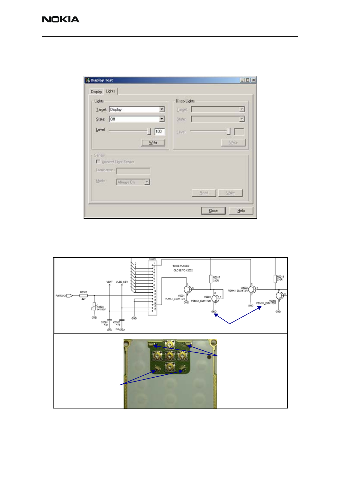
Display Phoenix Interface
Run the Display Test in Phoenix to check the display. Click Write to turn on the display
and keypad backlight.
Figure 34: Lights tab on the Display Test dialog box
Keypad Backlight Troubleshooting
When troubleshooting the keypad backlight, make these common checks.
Standby LED (blue)
Standby LED driver
Backlight LED (white)
Figure 35: Keypad backlight troubleshooting
Issue 1 - September 2006 Company Confidential Page 29
Page 30
6275/6275i (RM-154)
Baseband Description and Troubleshooting Nokia Customer Care
• If the keypad malfunctions, check the switch soldering and the B2B connection.
If okay, check the keypad ASIP and the D2800.
• If the standby LED does not work, check the connection of the B2B connector
and above the circuit.
The baseband supports three microphone inputs and two earpiece outputs. The
microphone inputs are:
• MIC1 - used for the mobile terminal's internal microphone
• MIC2 - used for headsets connected to the Pop-port connector
• MIC3 - used for the Universal Headset
Each microphone input can have either a differential or single-ended AC connection to
the UEMEK circuit. The internal microphone (MIC1) and external microphone (MIC2) for
are both differential for Pop-port accessory detection. However, the Universal Headset
interface is single ended. The microphone signals from different sources are connected to
separate inputs at UEMEK. Inputs for the microphone signals are differential types. Also,
MICB1 is used for MIC1, and VFLASH1 is used for MIC2 and MIC3 (Universal Headset).
Audio Troubleshooting
Use the following to troubleshoot the audio:
• Perform a visual inspection of all the ASIPs and the UEMEK.
• Inject a 1KHz signal into MiC1 and trace it to the earpiece. The signal is amplified
by a factor of x8 only when you use an IHF signal.
Not installed
DC block capacitors
Audio ASIPs
Audio ASIPsAudio ASIPs
FM radio lines
Figure 36: Audio troubleshooting - UEMK side
• Ensure that the audio amplifier and the solder are okay.
• Check the IHF Speaker contacts.
• Check that the output is amplified by 8X. If not, ensure that the gain resistor
network is correct.
Page 30 Company Confidential Issue 1 - September 2006
Page 31
6275/6275i (RM-154)
Nokia Customer Care Baseband Description and Troubleshooting
DC block capacitors
IHF
Audio amplifier
Figure 37: Audio troubleshooting
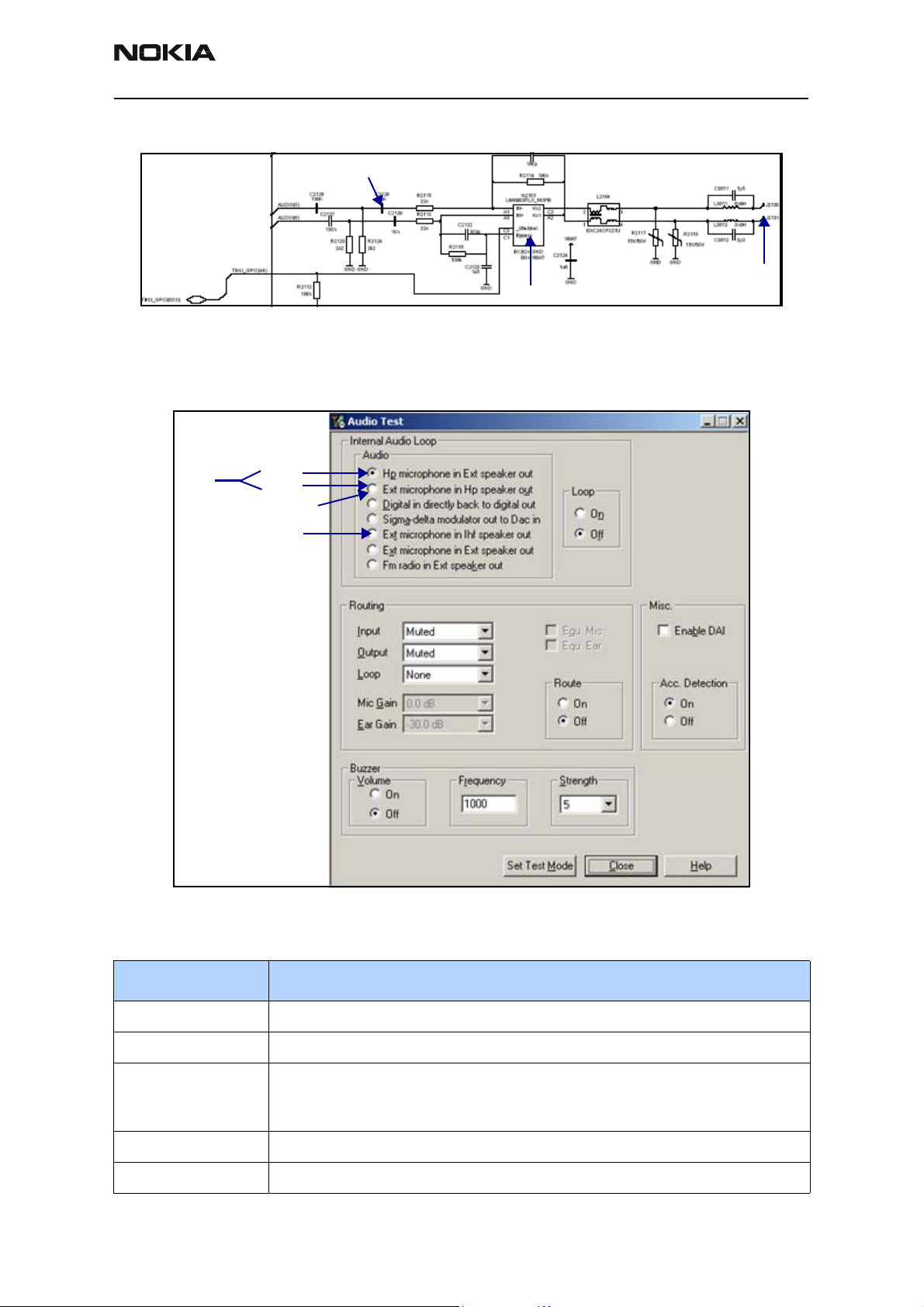
Audio Phoenix Interface
Run the audio test in Phoenix to check the audio functionality.
MIC3
MIC1
MIC2s
Earpiece
IHF
Figure 38: Audio Test in Phoenix
Table 1: Audio Test Parameters
Audio Component Description
MIC1 Routes the audio from the internal microphone to the headset speaker.
MIC2 Routes the audio signal from the headset microphone to the internal earpiece.
MIC3 Use the first and second options on the Phoenix menu to have an open channel. When
you insert the Universal Headset, the UEM automatically reroutes the audio signal to
the UHJ.
Earpiece Allows you to use to hear a signal from the internal earpiece.
IHF Routes the audio signal to the IHF speaker output.
Issue 1 - September 2006 Company Confidential Page 31
Page 32

6275/6275i (RM-154)
Baseband Description and Troubleshooting Nokia Customer Care
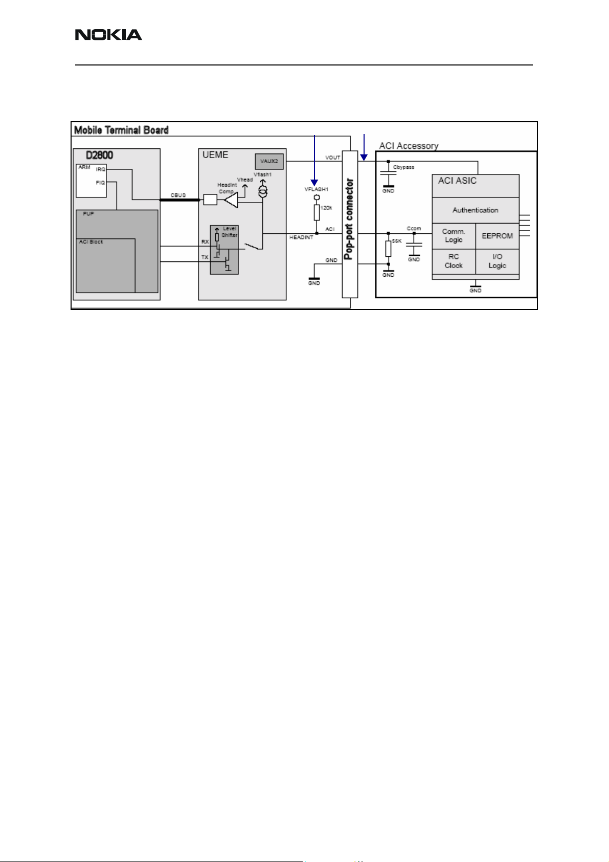
System Connector
The system connector is the Pop-port connector as shown in Figure 39. The mobile
terminal supports Pop-port (differential) and Universal Headset (single-ended)
accessories. The ACI signal detects the Pop-port accessory, while TIKU_GENIO(4) detects
the Universal Headset.
Figure 39: System Connector
There are 14 circuits connected through the system connector:
• Charge = Connects to the charging system
• Charge GND = Grounds the charging system
• ACI = Accessory Control Interface
• Vout = External accessory power supply
• USB Vbus = USB power supply (5V)
• USB D+ = USB data line (positive)
• USB D- = USB data line (negative)
• XMIC N = Differential connection to the MIC for the external microphone
• XMIC P = Differential connection to the MIC for the external microphone
• HSEAR N = Differential headset connection to the external EAR
• HSEAR P = Differential headset connection to the external EAR
• HSEAR R N = Differential headset connection to the external stereo
• HSEAR R P = Differential headset connection to the external stereo
Page 32 Company Confidential Issue 1 - September 2006
Page 33
6275/6275i (RM-154)
Nokia Customer Care Baseband Description and Troubleshooting
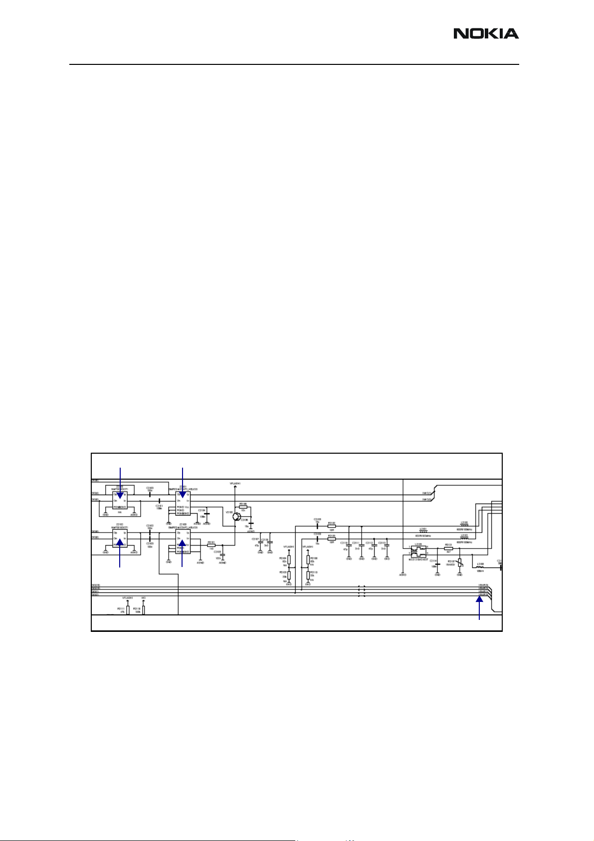
VFLASH1 (2.78V)
Figure 40: Accessory Detection Diagram
VAUX2 (2.78V)
Issue 1 - September 2006 Company Confidential Page 33
Page 34

6275/6275i (RM-154)
Baseband Description and Troubleshooting Nokia Customer Care
Flash Programming
Flashing Tool
• BSI = Used to indicate to the MCU that the prommer is connected and the mobile
terminal is in flashing mode.
• MBUS = Used as a clock signal for synchronizing the serial communication
between the prommer and the MCU.
• FBUSRX = Data to the D2800.
• FBUSTX = Data to the prommer.
• VPP = 0v/1.8v/8.8V (read only/normal operation or slow programming/fast
programming).
Flashing Phoenix Interface
1. Run EZ Flash in Phoenix to flash the mobile terminal.
Figure 41: EZ Flash in Phoenix
2. Click Select to search for the appropriate software.
Figure 42: EZ Flash in Phoenix
Page 34 Company Confidential Issue 1 - September 2006
Page 35

6275/6275i (RM-154)
Nokia Customer Care Baseband Description and Troubleshooting
3. After selecting the correct software package, click Flash to write the software to
the mobile terminal.
Issue 1 - September 2006 Company Confidential Page 35
Page 36

6275/6275i (RM-154)
Baseband Description and Troubleshooting Nokia Customer Care
Battery (Lynx) Interface Circuit
Check the battery BSI voltage levels in the following power up modes:
• Normal mode: 1.23V
• Test mode: 170mV
• Local mode: 90mV
Page 36 Company Confidential Issue 1 - September 2006
Page 37

6275/6275i (RM-154)
Nokia Customer Care Baseband Description and Troubleshooting
Charging
Use the following items to troubleshoot charging issues:
1. Ensure that the battery bar scrolls.
2. Ensure that the voltage at V2000 is >3VDC.
3. Use Phoenix to ensure that the BTEMP ADC is ~25 C. If not, replace the UEM.
4. Remove the fuse at F2000, and measure the current with an AC-3. If it is not
~350mA, replace the UEM.
Figure 43: Charging troubleshooting diagram
Issue 1 - September 2006 Company Confidential Page 37
Page 38

6275/6275i (RM-154)
Baseband Description and Troubleshooting Nokia Customer Care
Alignment
Alignment consists of using the production Flali station to check the following:
• Initial current for quick short circuit detection
• Flashing the mobile terminal
• Baseband self-test for integrity check circuit interconnections
• Baseband calibrations:
•ADC
•VBAT
• VCHAR and ICHAR
•BSI
•Btemp
• RF calibrations
Page 38 Company Confidential Issue 1 - September 2006
Page 39

6275/6275i (RM-154)
Nokia Customer Care Baseband Description and Troubleshooting
AMS Baseband Calibration
Use the AMS baseband calibration to perform the following tests:
• ADC - Verify and calibrate the gain and offset for 11 channels analog to digital
converter in the UEM.
• VBAT - Calibrate the gain and offset of the battery input path for accurate
battery level monitoring.
• VCHAR and ICHAR – Verify the charging circuit and path calibrate gain and
offset for correct charger detection.
• BSI – Calibrate the gain of the BSI line for battery size information upon
powering up.
• Btemp – Calibrate gain of Btemp for battery temperature monitoring during
charging for over temperature shut down.
Issue 1 - September 2006 Company Confidential Page 39
Page 40

6275/6275i (RM-154)
Baseband Description and Troubleshooting Nokia Customer Care
Final UI Check
Final UI performs basic user interface, audio and accessory tests on the baseband:
• Ensures that all keymats work.
• Ensures that the internal mic and earpiece work.
• Checks that the LCD module is functioning correctly.
• Ensures that all the external system and charger contacts are properly assembled.
• Ensure that general call processing is correct.
Page 40 Company Confidential Issue 1 - September 2006
Page 41

6275/6275i (RM-154)
Nokia Customer Care Baseband Description and Troubleshooting
Problems During Flash and Alignment
The following topics discuss potential problems that can occur during Flash and
Alignment.
No Communication - Flash
Ensure a good connection between the flash adaptor and mobile terminal.
• You must power the mobile terminal by a prommer (e.g., FPS-8).
• Check the baseband regulators: VR3, VIO, VCORE, VFLASH1.
• You must have 19.2Mhz clock into the D2800 in order to flash the mobile
terminal.
• Check the BSI, MBUS, FBUSRx, FBUSTx, PURX, SLEEPX for bad solder joints
between the UEM and the D2800.
• Check the flash bus signal and VPP voltage level.
No Communication - Alignment
• Check all connections between the test fixture, cables, and the mobile terminal.
• Make sure the mobile terminal is in Local Mode, and check the VBAT voltage and
current levels. If not in Local Mode, check the BSI signal level.
• Make sure mobile terminal was programmed/Flashed.
Failed Self Test/Calibration
• Make sure the mobile terminal is in Local Mode.
• Make sure power supply provides enough current (~500mA and 2A for tuning).
• Use the troubleshooting guide’s troubleshooting flow chart to verify the failed
circuit.
• Check the signals and voltage levels.
Issue 1 - September 2006 Company Confidential Page 41
Page 42

6275/6275i (RM-154)
Baseband Description and Troubleshooting Nokia Customer Care
Other Potential Problems
Mobile Terminal Does Not Power Up
• Check the baseband regulators – VR3, VIO, VFLASH1, VCORE dc/dc, PURX.
• Check VCTCXO 19.2MHz signal at the D2800 input.
• Check the power up sequence.
• Check Flash IC, flash bus signals, and voltage level.
Shutdown after 32 Seconds
• Check for the absence of 32KHz SleepCLK.
• Check for incorrect SleepX and PURX signal levels.
• Check if the ESN number was corrupted.
No Audio
• Check for bad contacts or damaged earpiece.
• Check for bad connections at the microphone.
• Check for broken or bad solder joint of transistors and audio ASIPs.
• Verify the audio signal paths using baseband “audio test” component with
Phoenix.
Keypad Malfunction
• Check for protective film left on the back of the key dome if a new one was
installed.
• Check for corrosion on the keypad and keydome.
• Check if the flash software was corrupted.
• Check for a bad joint from the D2800 to the Z2400 interface.
• Check for damage on the Z2400.
No LCD Display
• Check for bad connections.
• Check for a cracked or damaged display.
• Probe test points for missing or incorrect signal levels.
Page 42 Company Confidential Issue 1 - September 2006
Page 43
6275/6275i (RM-154)
Nokia Customer Care Baseband Description and Troubleshooting
Phoenix Tools
Figure 44: Phoenix Software Main Window
The following section provides information about the Phoenix software and how you can
use it to troubleshoot and correct problems in the baseband component of the mobile
terminal.
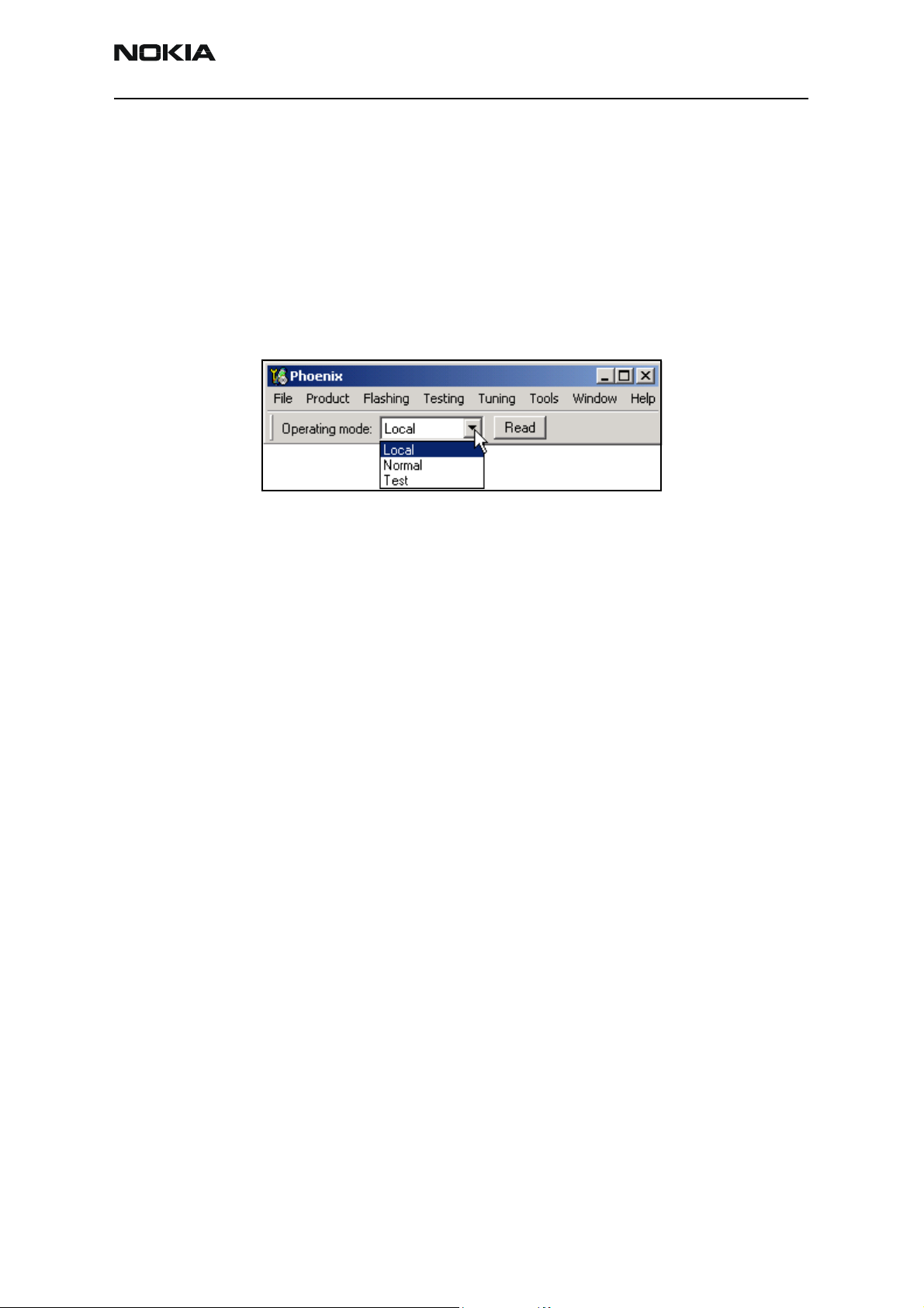
Local Mode
Although most Nokia mobile terminals automatically come up in Local Mode, ensure the
mobile terminal setting is set to Local Mode.
Figure 45: Setting Local Mode in Phoenix
Reading the Mobile Terminal
Figure 46: File menu in Phoenix
1. Open the File menu, and click Scan Product. Phoenix scans the product and
displays the applicable menus and commands.
Figure 47: Phone Information Window in Phoenix
Running the Self Test
Running the Self Test is one way of quickly finding where a problem might be in the
mobile terminal.
Figure 48: Open the Testing menu, and click Self Test.Self Test Command in Phoenix
Figure 49:
The Self Test window appears. Click Start to initiate the self test. Self Tests Command in
Phoenix
Checking the Baseband Regulator/General I/O parameters
Figure 50: Baseband Regulator/General I/O Command in Phoenix
Figure 51:
Click Get All to display all of the parameters.Baseband Regulator/General I/O Command in
Phoenix
Flashing the Mobile Terminal
Figure 52: Flashing Menu
Flashing - EZ-Flash
1. To EZ-Flash the mobile terminal,
Figure 53: EZ Flash Command in Phoenix
2. After retrieving the file, click Flash to begin flashing the mobile terminal.
Issue 1 - September 2006 Company Confidential Page 43
Page 44

6275/6275i (RM-154)
Baseband Description and Troubleshooting Nokia Customer Care
Signal References
Figure 54: Signal References
Page 44 Company Confidential Issue 1 - September 2006
Page 45

6275/6275i (RM-154)
Nokia Customer Care Baseband Description and Troubleshooting
Issue 1 - September 2006 Company Confidential Page 45
Page 46

6275/6275i (RM-154)
Baseband Description and Troubleshooting Nokia Customer Care
Page 46 Company Confidential Issue 1 - September 2006
Page 47

6275/6275i (RM-154)
Nokia Customer Care Baseband Description and Troubleshooting
Issue 1 - September 2006 Company Confidential Page 47
Page 48

6275/6275i (RM-154)
Baseband Description and Troubleshooting Nokia Customer Care
Page 48 Company Confidential Issue 1 - September 2006
 Loading...