

Send feedback
Recommend Change in
KICS
Rate this page in KICS
E-mail
careacademy@microsoft.com
Service Manual for L1 and L2
Nokia Lumia 638 4G
RM-1010
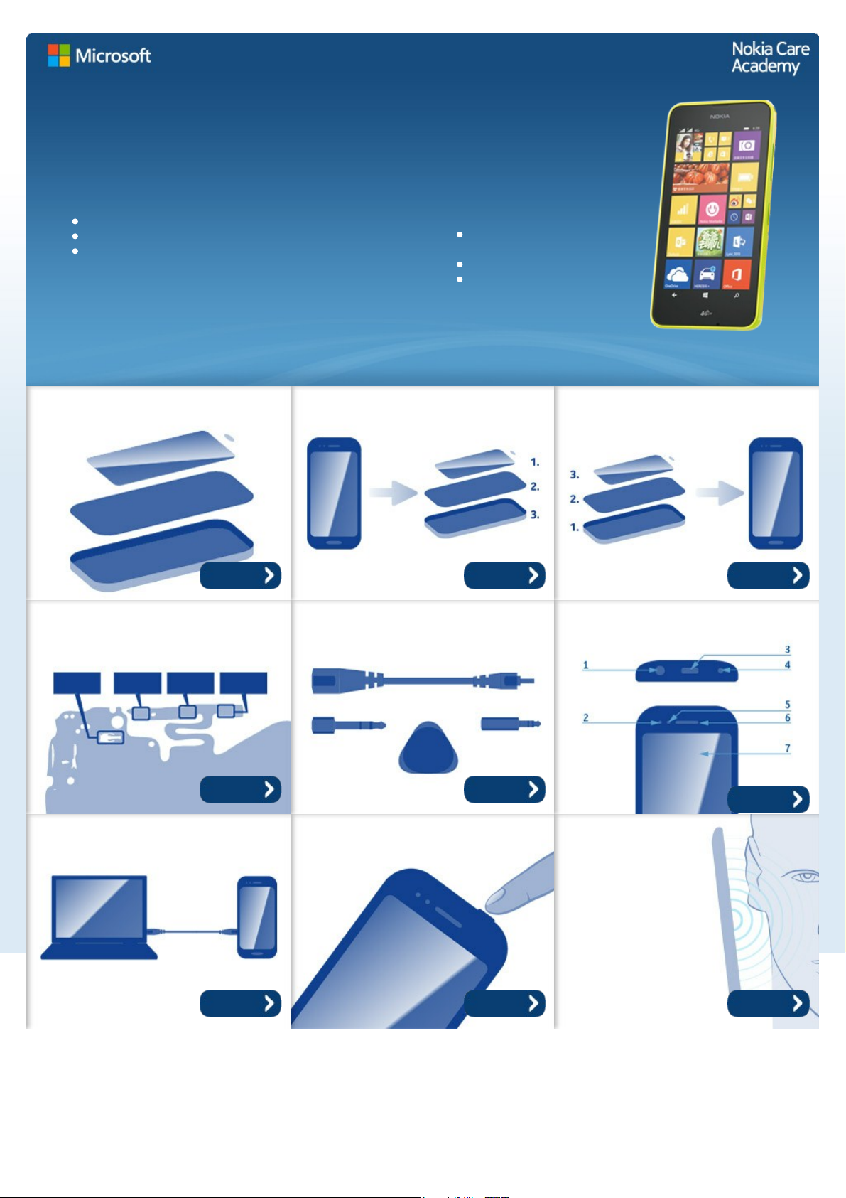
Key features
Windows Phone 8.1
4.5" LCD display
1.2 GHz Quad Core processor
Version 2.0
Note: Check the repair policy before performing
any mechanical repair on Service Level 1&2!
Exploded view Disassembly steps Assembly steps
Solder components Service devices Product controls and
interfaces
Service concept Phone reset
Proximity sensor
troubleshooting
©2014 Microsoft | Internal Use only
More More More
More More
More
More More More

Service Manual Level 1 and 2
Nokia Lumia 638 4G
RM-1010
Version 2.0
Version
history
Version Date Description
1.0 29.05.2014 First published version
2.0 11.06.2014 First version published to KICS
©2014 Microsoft | Internal Use only
Service Manual Level 1 and 2
Nokia Lumia 638 4G
RM-1010
Version 2.0
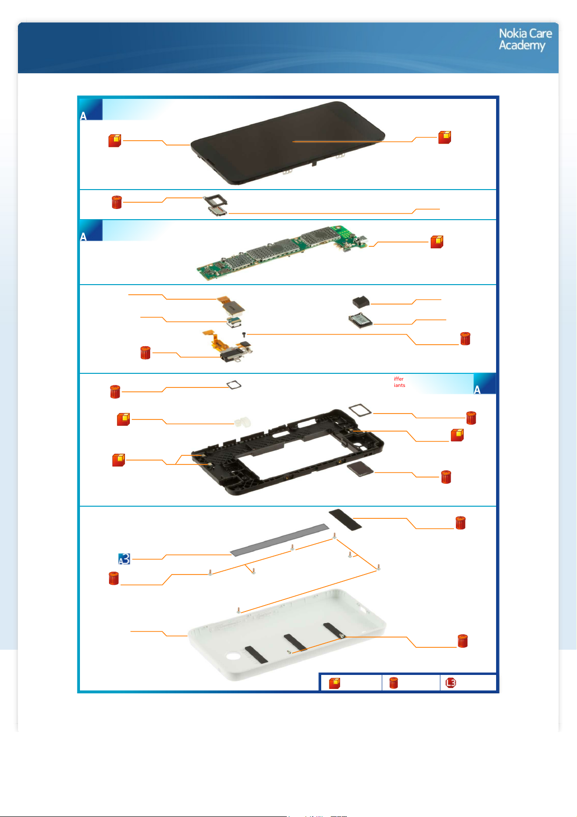
Exploded
view
WINDOW FRAME
I0001
CAMERA FLEX
I0016
CAMERA
I0017
TOP FLEX
I0015
VIBRA BOOT
I0007
*NOTE: Ordering code differ
between the variants
*NOTE: Ordering code
differ between
the variants
CWS ANTENNA
I0005
BACK COVER
I0022
CAMERA GASKET
I0008
TYPE LABEL
I0012
EARPIECE PLATE
I0003
DISPLAY
I0002
EARPIECE
I0004
LIGHT SWAP PACKAGE
I0011
USB BOOT
I0013
IHF SPEAKER
I0014
IHF SPEAKER GASKET
I0009
ANTENNA 3G/
ANTENNA LTE
I0006
IHF MESH
I0010
MAIN ANTENNA
HOLE ADHESIVE
I0021
SCREW TORX+
SIZE 4 RF1.4 X 3.0
I0018
SCREW TORX+
SIZE 4 M1.4 x 2.5
I0020
SCREW TORX+
SIZE 4 M1.4 x 3.4
I0019
LIGHT SWAP PACKAGE
(I0011, I0012)
3
DISPLAY ASSEMBLY
(I0001, I0002)
1
CHASSIS ASSEMBLY
(I0005 - I0010)
2
Only available
as assembly
Not reuseable
after removal
Repair/swap
only in level 3
©2014 Microsoft | Internal Use only
Service Manual Level 1 and 2
Nokia Lumia 638 4G
RM-1010
Version 2.0
Disassembly
steps
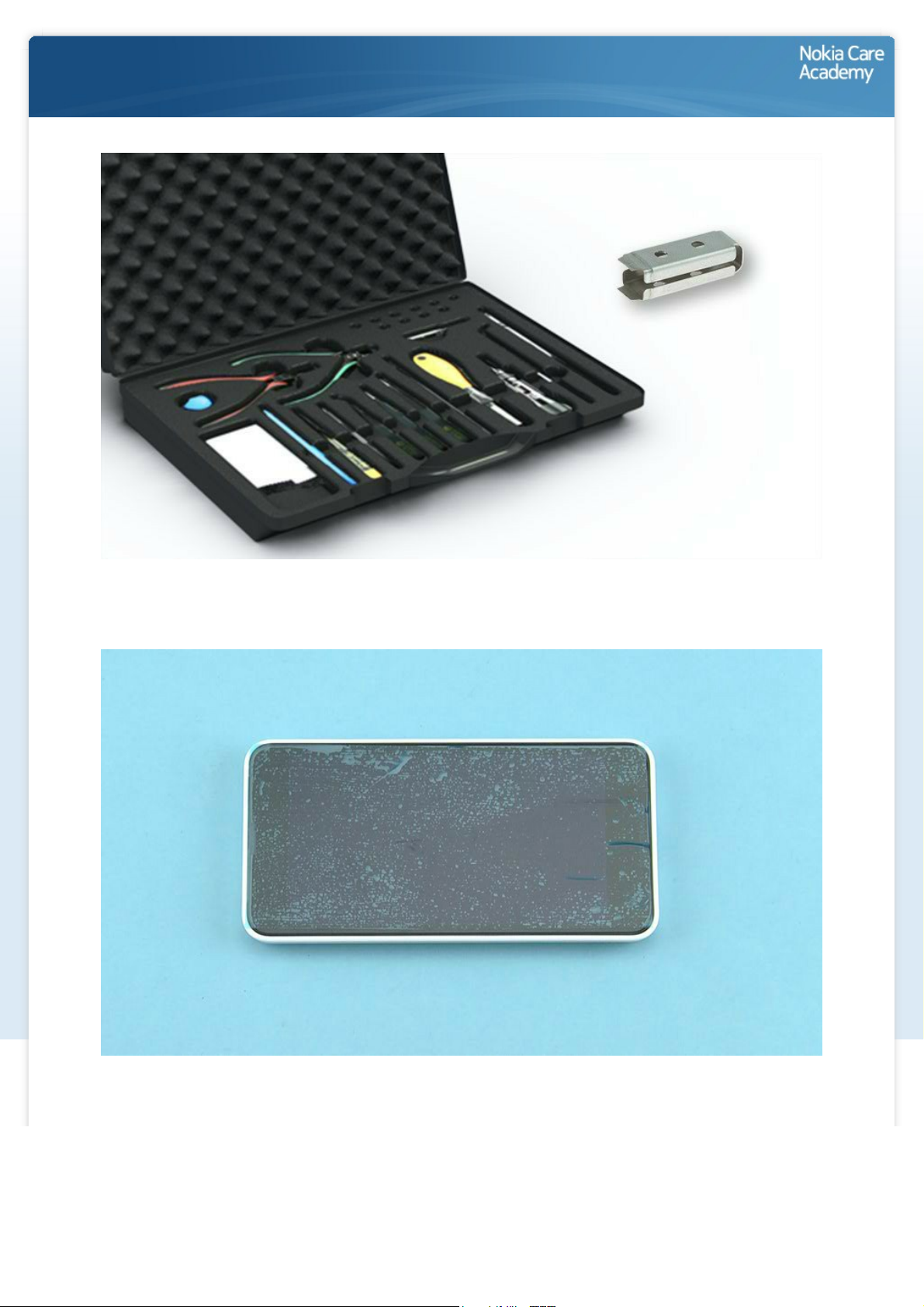
1) For disassembling you need the Nokia Standard toolkit version 2. You will also need the camera removal
tool SS-305.
2) Protect the DISPLAY with protective film.
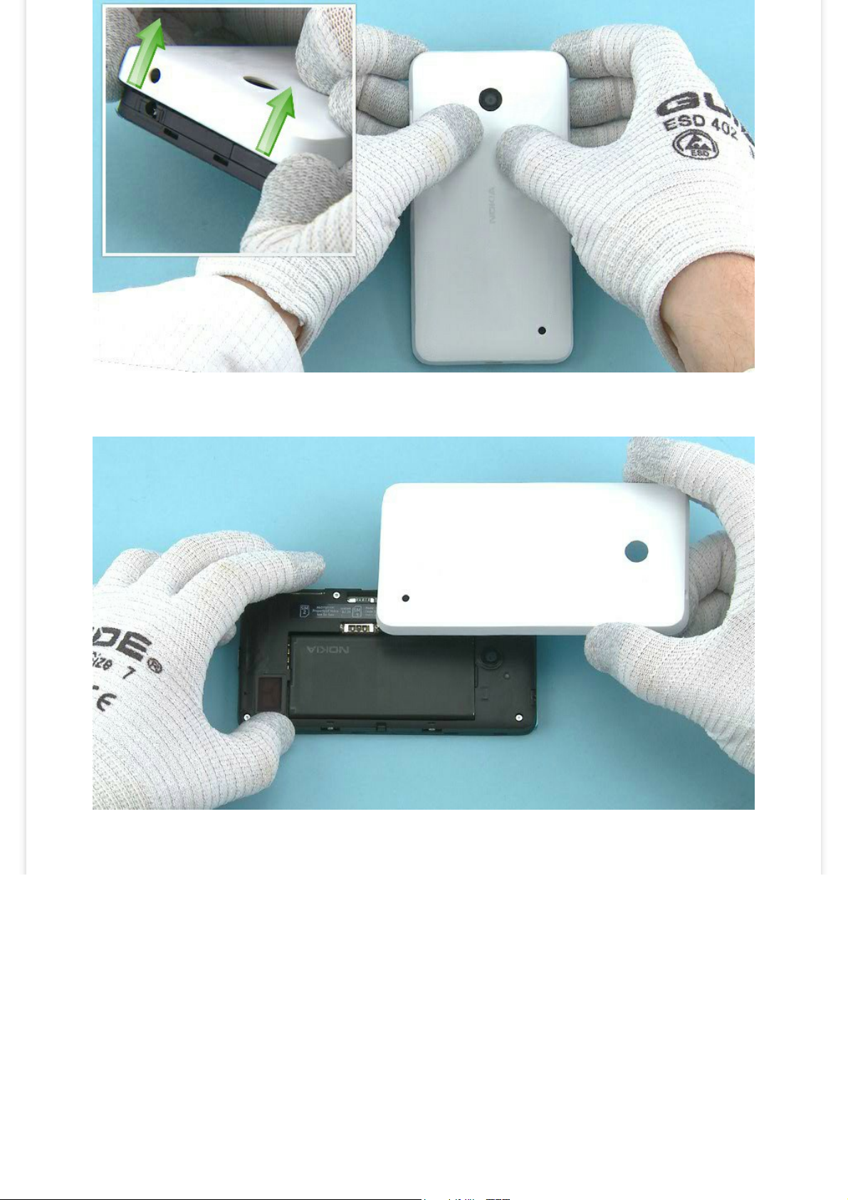
3) Release the BACK COVER by pulling from the both top end corners as shown.
4) Lift up and remove the BACK COVER.

5) If there is battery inserted, remove it by using the shown finger notch.
6) Lift up one corner of the MAIN ANTENNA HOLE ADHESIVE with the dental tool. Peel off and discard the
MAIN ANTENNA HOLE ADHESIVE.
Be careful not to injure yourself or the device with the sharp end of the dental tool.
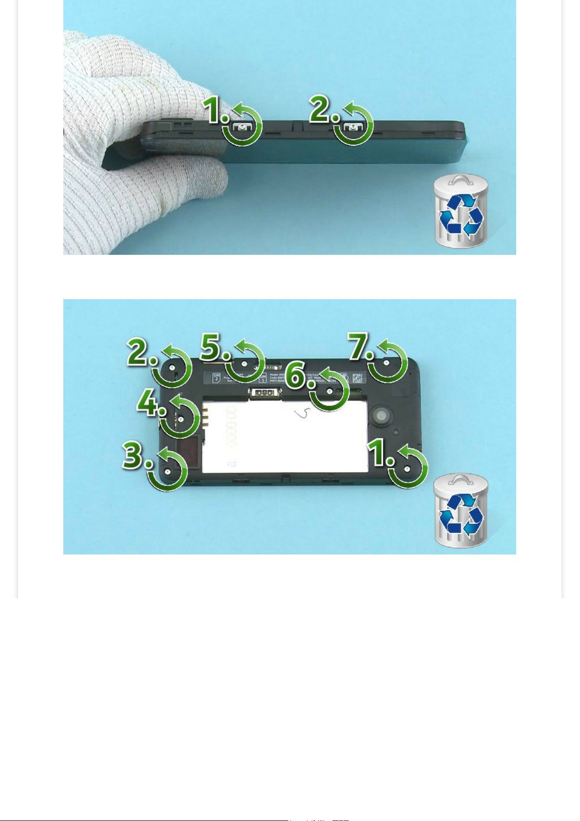
7) Unscrew the two TORX+ size 4 screws in the order shown. Do not use them again. Discard them.
8) Unscrew the seven TORX+ size 4 screws in the order shown. Do not use them again. Discard them.
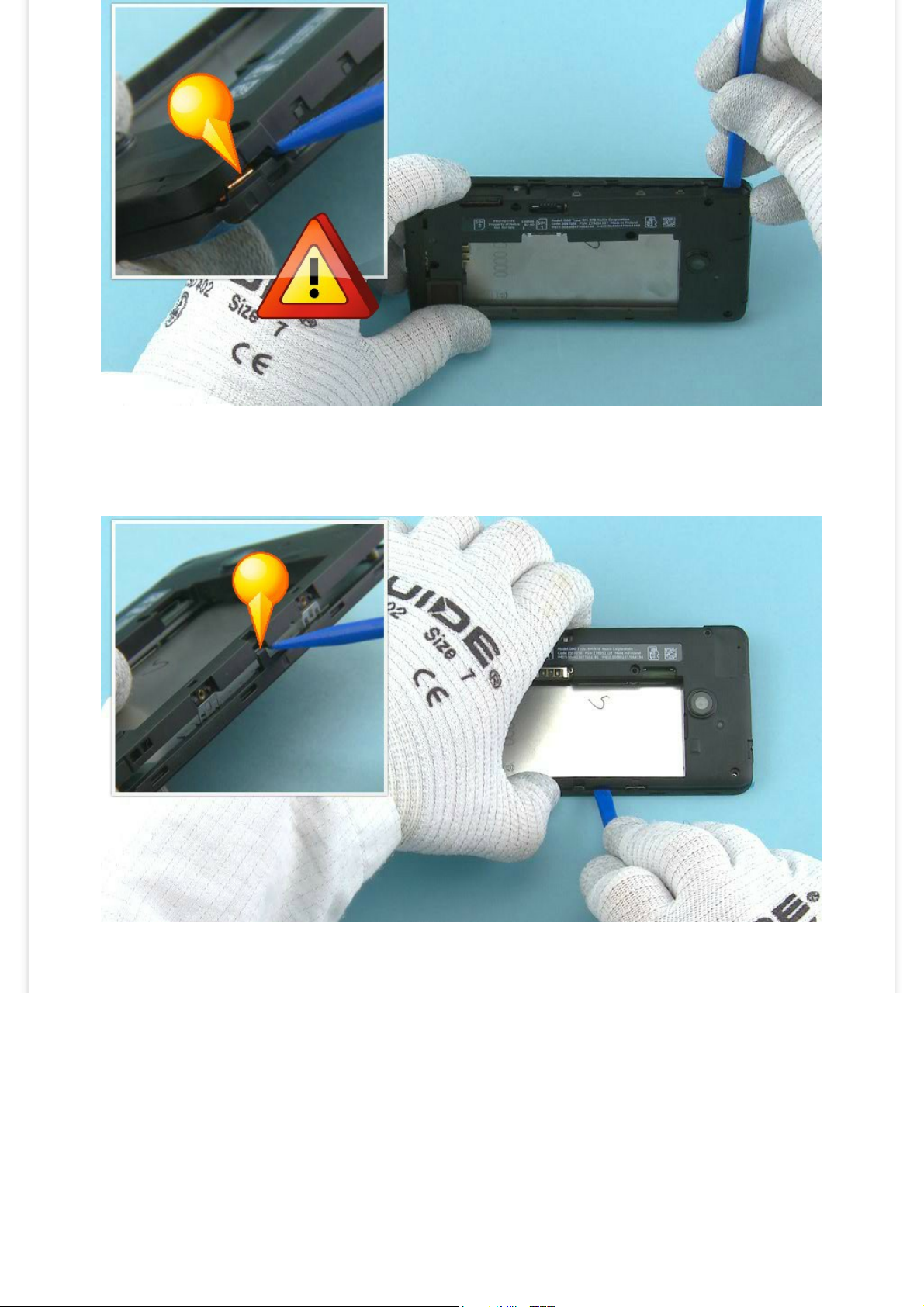
9) Use the SS-93 to carefully release the CHASSIS ASSEMBLY from the DISPLAY ASSEMBLY.
Be careful not to damage the shown flex.
10) Use the SS-93 to release the shown clip on the other side of the device.
11) Turn the CHASSIS ASSEMBLY as shown and open the DISPLAY connector. The DISPLAY ASSEMBLY can be
separated once the connector is opened.
Be careful not to bend the flex or damage the connector.
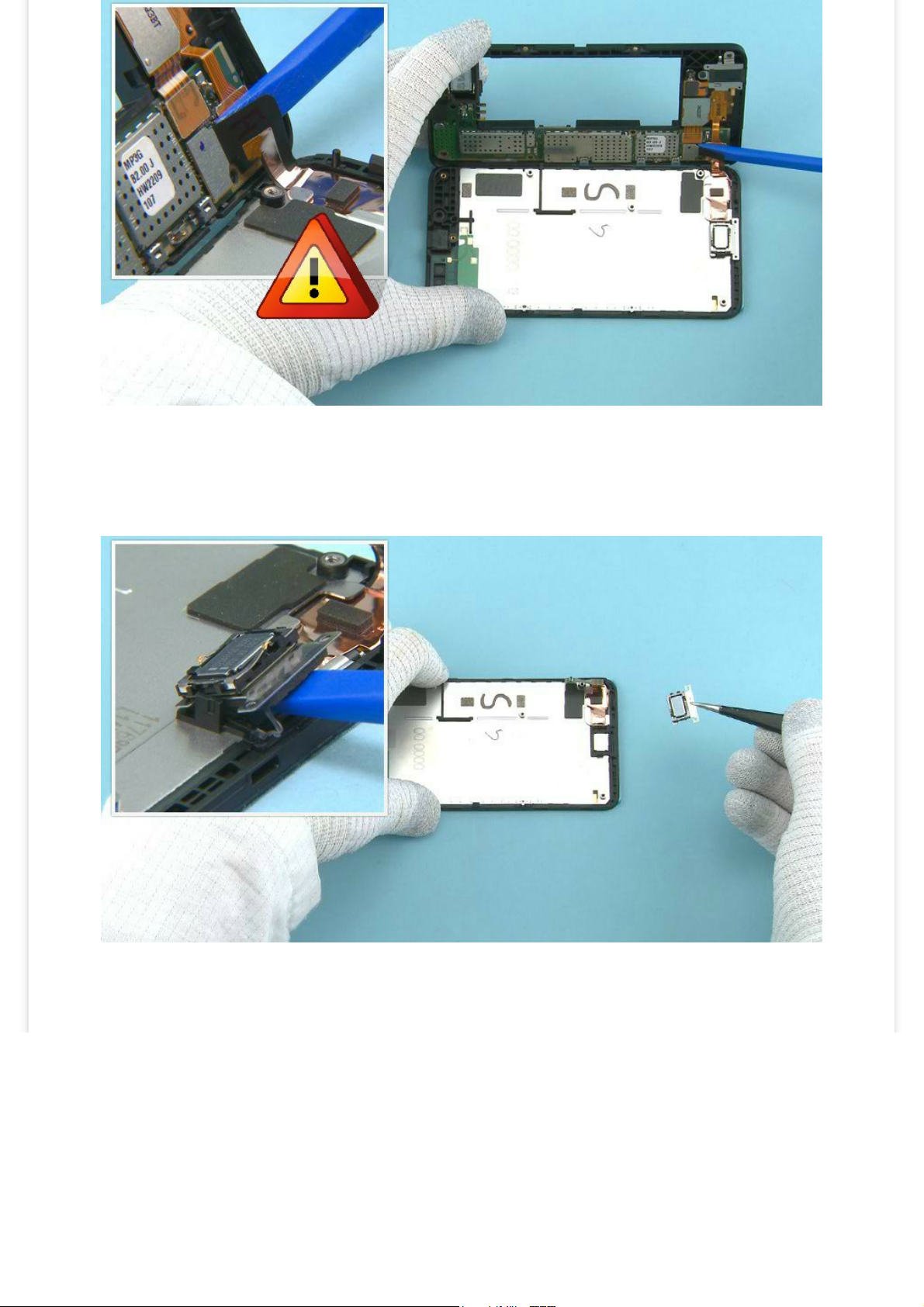
12) Push the SS-93 under the EARPIECE PLATE to release it. Make sure to remove all EARPIECE PLATE
adhesive remains from the DISPLAY ASSEMBLY.
13) Use the dental tool to separate the EARPIECE from the EARPIECE PLATE. Do not use the EARPIECE
PLATE again. Discard it.
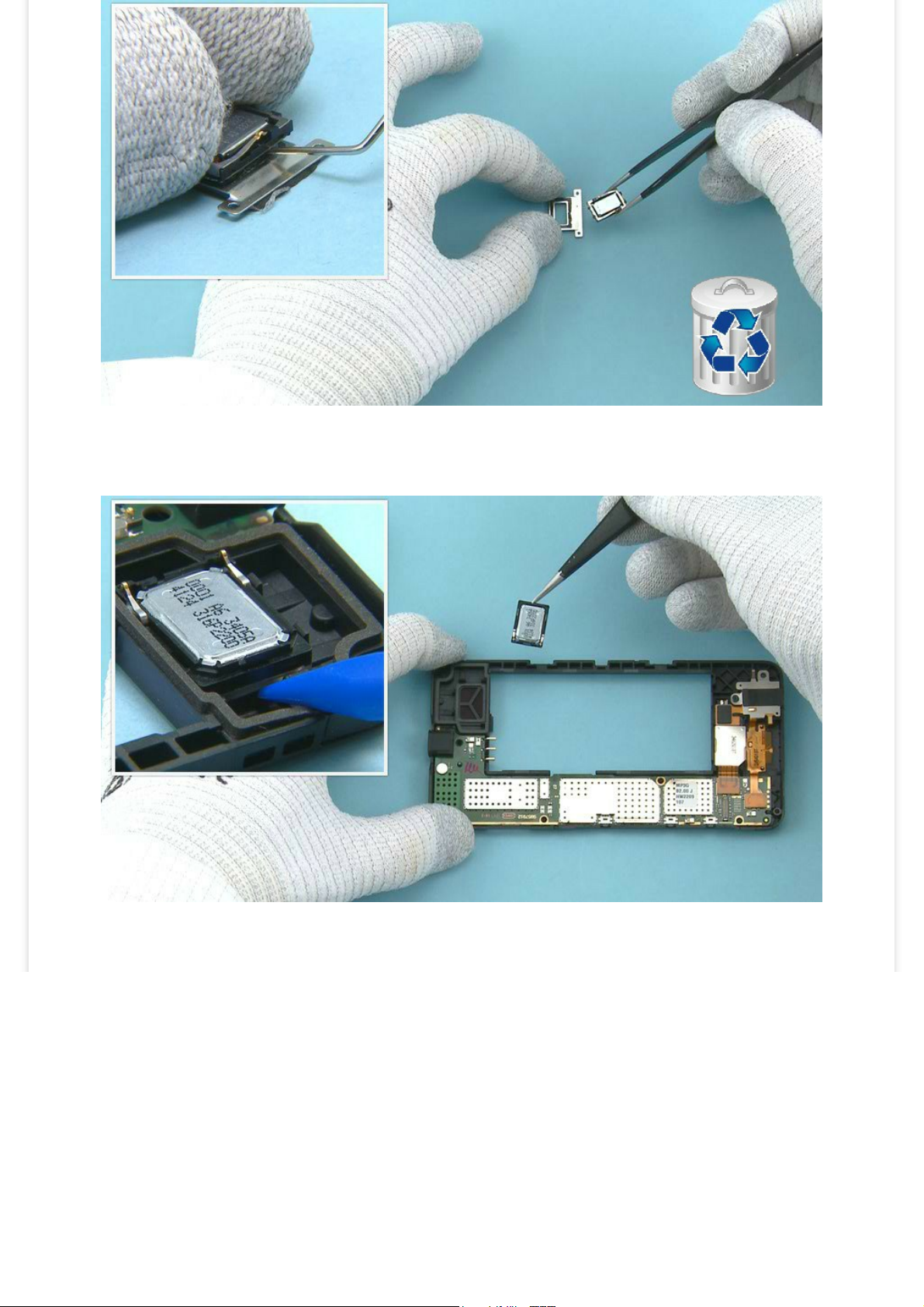
14) Push the sharp end of the SS-93 under the IHF SPEAKER to release it. Remove it with tweezers.
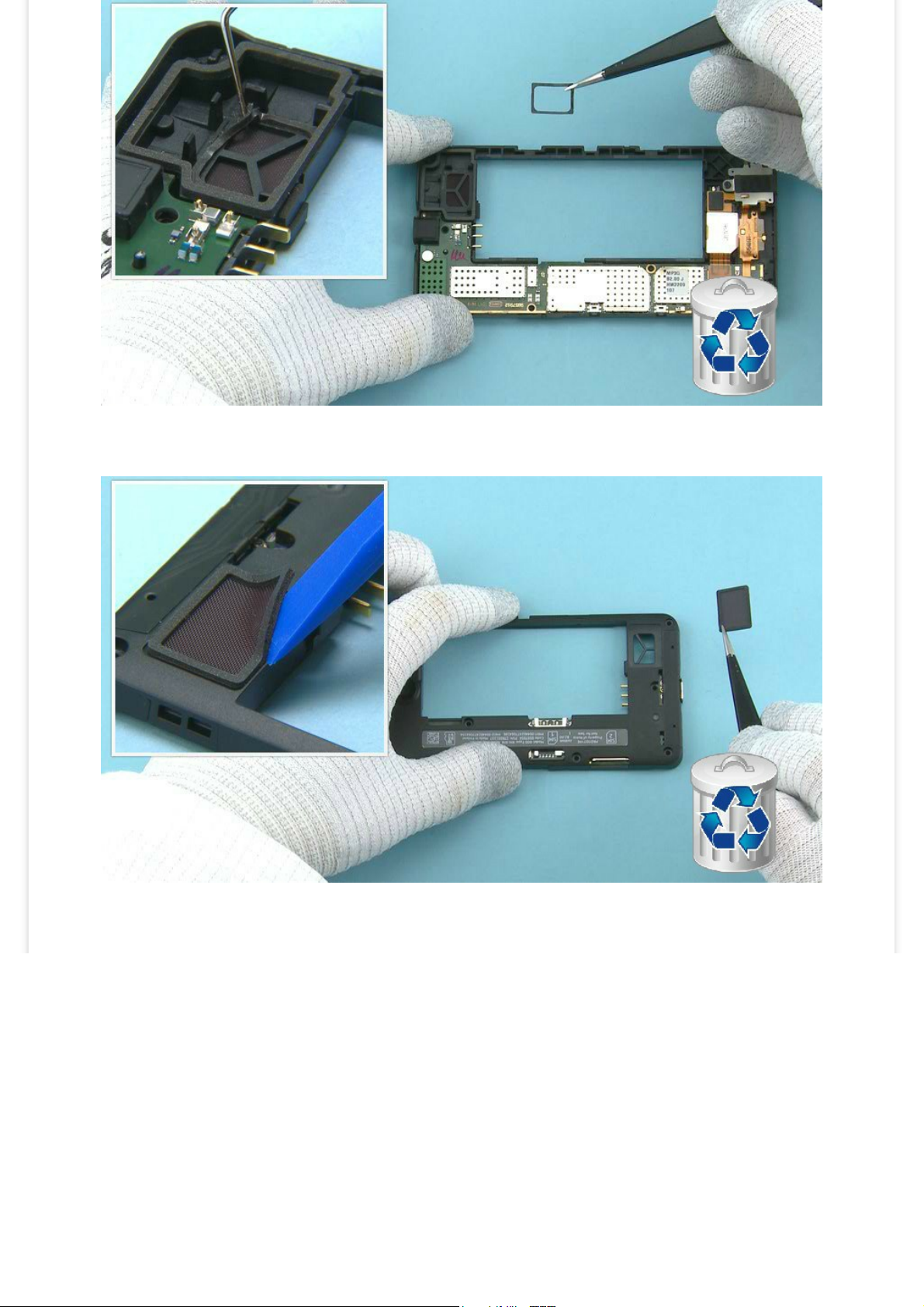
15) Release the IHF SPEAKER GASKET with dental tool. Remove and discard the IHF SPEAKER GASKET.
16) Use the SS-93 to release the IHF MESH. Remove and discard the IHF MESH.
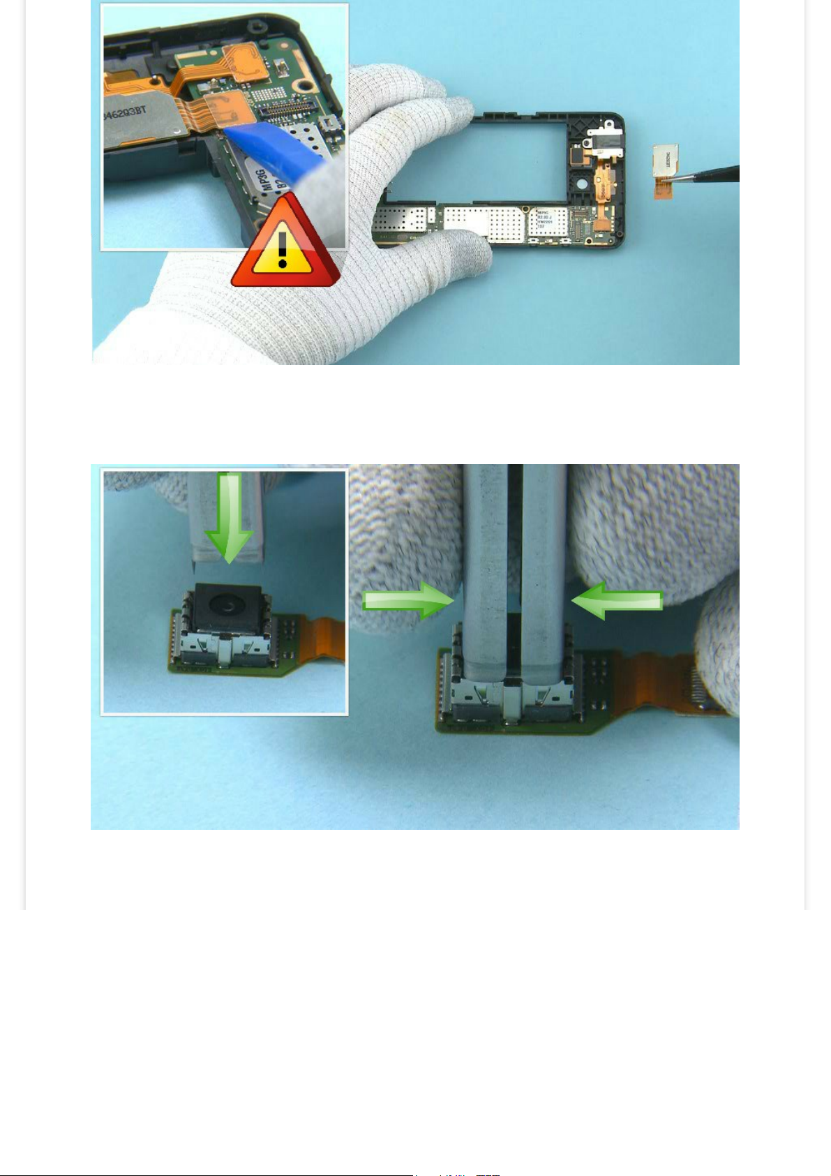
17) Open the CAMERA connector with the SS-93. Remove the CAMERA FLEX and CAMERA.
Be careful not to damage the connector or any nearby components.
18) Place the SS-305 camera removal tool on top of the CAMERA as shown. Note the alignment. Push
down the SS-305 until the camera retaining clips are released. Hold from the sides of the SS-305.
19) Pull up the SS-305 while holding from the sides of it and remove the CAMERA.
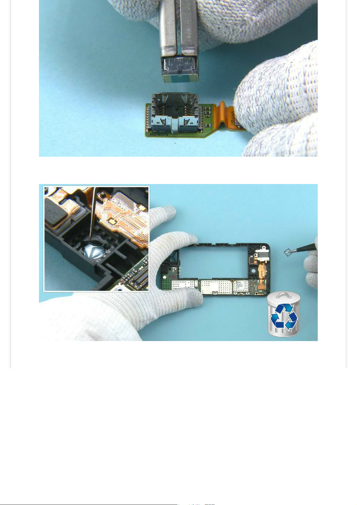
20) Use dental tool to remove the CAMERA GASKET. Do not use it again. Discard it.

21) Unscrew the shown TORX+ size 4 screw. Discard it.
22) Open the TOP FLEX connector with the SS-93.
Be careful not to damage the connector or any components nearby.

23) Use the sharp end of the SS-93 to lift up the vibra as shown.
24) Lift up also the AV connector.

25) Push the SS-93 under the flex part as shown.
26) Remove and discard the TOP FLEX.

27) Lift up the ENGINE BOARD from the shown place so that the shown two clips holding it are released.
28) The ENGINE BOARD can now be separated.

29) Remove the USB BOOT.
30) The Nokia Lumia 638 4G disassembly procedure is complete.
-END OF DISASSEMBLY-
©2014 Microsoft | Internal Use only

Service Manual Level 1 and 2
Nokia Lumia 638 4G
RM-1010
Version 2.0
Assembly
steps
1) For assembling you need the Nokia Standard toolkit version 2.
2) Remove the shown protective film from the EARPIECE PLATE.

3) Place the EARPIECE PLATE to the DISPLAY ASSEMBLY as shown. Align the EARPIECE PLATE with the two
shown guiding pins. Press the EARPIECE PLATE gently to activate the adhesive.
4) Remove the second EARPIECE PLATE protective film.

5) Hold the EARPIECE with tweezers as shown so that the pins does not get damaged. Place the EARPIECE
to the EARPIECE PLATE. Make sure to align the EARPIECE so that the guiding pins are as shown. Press the
EARPIECE gently to activate the adhesive.
Be careful not to damage the EARPIECE pins.
6) Place the USB BOOT as shown.

7) Place the ENGINE BOARD to the CHASSIS ASSEMBLY. Press the ENGINE BOARD as shown and make sure
the two shown clips are attached properly.
8) Remove the TOP FLEX protective film.

9) Place the TOP FLEX to the CHASSIS ASSEMBLY by using the two shown guiding pins. Press the flex part
gently to activate the adhesive.
10) Push the AV connector and the vibra to their places.

11) Connect the TOP FLEX connector with the SS-93.
Be careful not to damage the connector or any components nearby.
12) Fasten the shown TORX+ size 4 screw to torque of 10 Ncm.

13) Place the CAMERA to the CAMERA FLEX. Note the alignment of the CAMERA. Push down the CAMERA
from the sides of it until the camera retaining clips are fastened.
Be careful not to touch the CAMERA lens when pushing it down. Do not push black area near the CAMERA
lens, autofocus mechanism is located below that black plastic and can be easily damaged.
14) Remove the shown protective film from the CAMERA GASKET.

15) Place the CAMERA GASKET to the CHASSIS ASSEMBLY as shown. Push the CAMERA GASKET to activate
the adhesive.
16) Remove the shown CAMERA GASKET protective film.

17) Place the CAMERA FLEX to the CHASSIS as shown. Make sure to place it straight as the CAMERA
GASKET might move or bend and be visible in the CAMERA window if the CAMERA is placed in angle.
Connect the CAMERA connector.
Be careful not to damage the connector or any components nearby.
18) Remove the shown protective film from the IHF SPEAKER GASKET.

19) Place the IHF SPEAKER GASKET to its place and press it to activate the adhesive.
20) Remove the second IHF SPEAKER GASKET protective film.

21) Note the IHF SPEAKER alignment when placing it. Push the IHF SPEAKER gently to activate the
adhesive.
22) Remove the IHF MESH protective film.

23) Place the IHF MESH and press it gently to activate the adhesive.
24) Hold the DISPLAY ASSEMBLY as shown when connecting the DISPLAY connector.
Be careful not to damage the connector or any nearby components.

25) Turn over the DISPLAY ASSEMBLY on top of the CHASSIS ASSEMBLY and press them so that both sides
of the device are closed properly.
26) Fasten the seven TORX+ size 4 screws in the order shown to the torque of 11 Ncm.
Note that these seven screws are longer than the two screws shown in the next step.

27) Fasten the two TORX+ size 4 screws in the order shown to the torque of 12 Ncm.
Note that these two screws are shorter than the seven screws shown in the previous step.
28) Remove the shown protective film from the MAIN ANTENNA HOLE ADHESIVE.

29) Place the MAIN ANTENNA HOLE ADHESIVE as shown.
30) Press the MAIN ANTENNA HOLE ADHESIVE to activate the adhesive. Remove the protective film from
the MAIN ANTENNA HOLE ADHESIVE.

31) Place the BATTERY.
32) Place the DISPLAY ASSEMBLY to the BACK COVER bottom end first. Press the DISPLAY ASSEMBLY to
attach it properly to the BACK COVER.
The Nokia Lumia 638 4G assembly procedure is complete.
©2014 Microsoft | Internal Use only

Service Manual Level 1 and 2
Nokia Lumia 638 4G
RM-1010
Version 2.0
Solder
components
F1400
S4401S4402 S4403
X1000
X1001 X1002
X1003 X2104
X2105
X7902
X7900
X7901
X7903
Z5200
Camera
fuse
Power/Lock
key
Volume +
key
Volume -
key
Grounding
spring
Grounding
spring
Grounding
spring
Grounding
spring
IHF Speaker
spring
IHF Speaker
spring
MIMO
antenna
WLAN/GNSS
spring
MicroSD
ASIP
MIMO
antenna
Main
antenna
TOP
BOTTOM
©2014 Microsoft | Internal Use only

Service Manual Level 1 and 2
Nokia Lumia 638 4G
RM-1010
Version 2.0
Service
devices
CA-101 Service cable AC-20
AC-21C (Only for China)
SS-305 Camera removal tool
BL-5H Battery Nokia Standard Toolkit (v2)
For more information, refer to the Service
Bulletin (SB-011) on Nokia Online. Supplier or
manufacturer contacts for tool re-order can be
found in “Recommended service equipment”
document on Nokia Online.
©2014 Microsoft | Internal Use only

Service Manual Level 1 and 2
Nokia Lumia 638 4G
RM-1010
Version 2.0
Product controls and
interfaces
3
2
1
8
7
9
10
4
5
11
6
8 — Volume - key
7 — Volume + key
6 — Camera
5 — Micro-USB connector
4 — Microphone
3 — Touch screen
2 — Earpiece
1 — 3.5 mm AHJ connector
9 — Power/Lock key
10 — Loudspeaker
11 — Main antenna area
©2014 Microsoft | Internal Use only

Service Manual Level 1 and 2
Nokia Lumia 638 4G
RM-1010
Version 2.0
Service
concept
Flashing concept
CA-101
Service
software
Transceiver
Product specific
battery
©2014 Microsoft | Internal Use only

Service Manual Level 1 and 2
Nokia Lumia 638 4G
RM-1010
Version 2.0
Phone
reset
Step 1
Make sure the phone is turned Off.
1. Press and hold the power
key
2. Phone vibrates (release the
power key)
3. Press and hold the volume
down key
4. Exclamation mark is shown
on the screen (release the
volume down key)
Option 1: About menu
- Use this option if the consumer knows the lock code
- This option warns the consumer about data loss!
- Tap Settings > About > reset your phone
Software / operating system (OS) reset
The software / operating system (OS) reset returns the phone to its out-of-the-box state. Note that this
procedure erases all consumer data! Always first try to perform a hardware reset.
Option 2: Hardware key combination
- Use this option if the phone is locked and the consumer does not know the code
- Note: no warning about data loss!
- Do not advertise this feature to consumers!
Follow next steps to perform OS reset with phone keys.

Step 2
Input the following key
combination:
1. Volume up
2. Volume down
3. Power
4. Volume down
Step 3
The phone will reset and boot up
automatically
©2014 Microsoft | Internal Use only

Service Manual Level 1 and 2
Nokia Lumia 638 4G
RM-1010
Version 2.0
Proximity sensor
troubleshooting
Solutions to the possible problems are as follows:
Problem:
Display stays on during the call when phone is next
to the ear.
Solution:
Advice the customer to keep the phone closer to the
ear during the call. Cheek or ear should be in touch
with the display area of the phone, not the frame of
the phone.
Problem:
Display stays black when phone is removed from ear during the call or
Customer complains that phone display blinks or stays black when
headset, charger or both are connected.
Solutions:
1. Touch screen functions or proximity sensing may be affected by
humidity, rain drops, make-up, or dirt on the display. If your phone
touch screen becomes unresponsive, use a cleaning cloth to wipe the
touch screen clean. To avoid scratches on display do not use anything
that could scratch the display and do not use chemicals for cleaning.
2. Advice the customer that two short power key presses wake up the
display if it stays black in situation where is should be active.
3. Check that latest Phone SW is in use. That has the best proximity
sensing parameters.
4. Check that user has original Nokia headset and charger in use.
Display, Touch and Proximity sensing related troubleshoot
Proximity sensing
This phone does not have optical proximity sensor, like previous Nokia products. In this device touch
module is used for proximity sensing purpose. Proximity sensing works when call is active. When
conductive large object (e.g. face or ear) is in touch with display, display is turned off.
Troubleshooting on call related (proximity sensing) problems.

Problem:
Customer complains about accidental key presses during the call.
Solutions:
1.Touch screen functions or proximity sensing may be affected by
humidity, rain drops, make-up, or dirt on the display. If your phone
touch screen becomes unresponsive, use a cleaning cloth to wipe the
touch screen clean. To avoid scratches on display do not use anything
that could scratch the display and do not use chemicals for cleaning.
2. Check that latest Phone SW is in use. That has the best proximity
sensing parameters.
Problem:
Customer uses display protective foil.
Solution:
Advice the customer that protective foils may affect the functionality
of the touch screen.
Touch screen functions or proximity sensing may be affected by
humidity, rain drops, make-up, or dirt on the display. If your phone
touch screen becomes unresponsive, use a cleaning cloth to wipe the
touch screen clean. To avoid scratches on display do not use anything
that could scratch the display and do not use chemicals for cleaning.
Troubleshooting on general touch related problems.
NOTE! Customer problems above do not require change of the display module.
Changing the display module does not correct the situation. Updating the SW is
the right procedure as the latest SW has the best proximity sensing parameters.
©2014 Microsoft | Internal Use only
 Loading...