

Page 1

PAMS Technical Documentation
Chapter 6
TFE/K–2 SERVICE SOFT-
WARE INSTRUCTIONS
Original 09/97
Page 2

TFE/TFK–2
PAMS
Service Software Instructions
AMENDMENT RECORD SHEET
Amendment
Number
Date Inserted By Comments
Technical Documentation
6 – 2
Original 09/97
Page 3

PAMS
TFE/TFK–2
Technical Documentation
Service Software Instructions
TFE/K–2 SERVICE SOFTWARE INSTRUCTIONS
Contents
Introduction 6 – 5. . . . . . . . . . . . . . . . . . . . . . . . . . . . . . . . . . . . . . . . . . . .
General 6 – 5. . . . . . . . . . . . . . . . . . . . . . . . . . . . . . . . . . . . . . . . . . . . .
Required Servicing Equipment 6 – 5. . . . . . . . . . . . . . . . . . . . . . . . .
Mechanical Connections 6 – 6. . . . . . . . . . . . . . . . . . . . . . . . . . . . . .
Install Procedure 6 – 7. . . . . . . . . . . . . . . . . . . . . . . . . . . . . . . . . . . . .
Introduction to Service Software Package User Interface 6 – 8. . . . .
Service Software Hardware Environment 6 – 8. . . . . . . . . . . . . . . .
Service Software Environment 6 – 8. . . . . . . . . . . . . . . . . . . . . . . . .
Service Software Executables 6 – 9. . . . . . . . . . . . . . . . . . . . . . .
Command Line Parameters 6 – 9. . . . . . . . . . . . . . . . . . . . . . . . .
Common Properties of the User Interface 6 – 10. . . . . . . . . . . . . . . . . .
Login Dialog box 6 – 10. . . . . . . . . . . . . . . . . . . . . . . . . . . . . . . . . . . . .
Main Window 6 – 11. . . . . . . . . . . . . . . . . . . . . . . . . . . . . . . . . . . . . . . .
Menu Bar 6 – 13. . . . . . . . . . . . . . . . . . . . . . . . . . . . . . . . . . . . . . . . . . . .
Product 6 – 13. . . . . . . . . . . . . . . . . . . . . . . . . . . . . . . . . . . . . . . . . . .
Configure 6 – 14. . . . . . . . . . . . . . . . . . . . . . . . . . . . . . . . . . . . . . . . .
Tuning 6 – 14. . . . . . . . . . . . . . . . . . . . . . . . . . . . . . . . . . . . . . . . . . . .
Testing 6 – 14. . . . . . . . . . . . . . . . . . . . . . . . . . . . . . . . . . . . . . . . . . . .
Software 6 – 15. . . . . . . . . . . . . . . . . . . . . . . . . . . . . . . . . . . . . . . . . .
Dealer 6 – 16. . . . . . . . . . . . . . . . . . . . . . . . . . . . . . . . . . . . . . . . . . . .
View 6 – 16. . . . . . . . . . . . . . . . . . . . . . . . . . . . . . . . . . . . . . . . . . . . . .
Phone Identity Window 6 – 16. . . . . . . . . . . . . . . . . . . . . . . . . . .
Help 6 – 17. . . . . . . . . . . . . . . . . . . . . . . . . . . . . . . . . . . . . . . . . . . . . .
Mouse Cursors 6 – 17. . . . . . . . . . . . . . . . . . . . . . . . . . . . . . . . . . . . . . .
Reserved Keys 6 – 17. . . . . . . . . . . . . . . . . . . . . . . . . . . . . . . . . . . . . . .
Short Cut Function Keys 6 – 17. . . . . . . . . . . . . . . . . . . . . . . . . . . .
Alt Hot Keys 6 – 17. . . . . . . . . . . . . . . . . . . . . . . . . . . . . . . . . . . . . . .
Ctrl Hot Keys 6 – 18. . . . . . . . . . . . . . . . . . . . . . . . . . . . . . . . . . . . . .
Shift Hot Keys 6 – 18. . . . . . . . . . . . . . . . . . . . . . . . . . . . . . . . . . . . .
Key Strokes 6 – 18. . . . . . . . . . . . . . . . . . . . . . . . . . . . . . . . . . . . . . .
Help Functions 6 – 20. . . . . . . . . . . . . . . . . . . . . . . . . . . . . . . . . . . . . . .
Dialog Boxes 6 – 20. . . . . . . . . . . . . . . . . . . . . . . . . . . . . . . . . . . . . . . .
Common Dialog boxes 6 – 20. . . . . . . . . . . . . . . . . . . . . . . . . . . . . .
Note Message Box 6 – 20. . . . . . . . . . . . . . . . . . . . . . . . . . . . . . .
Query Message Box 6 – 21. . . . . . . . . . . . . . . . . . . . . . . . . . . . .
Error Message Box 6 – 21. . . . . . . . . . . . . . . . . . . . . . . . . . . . . .
Custom Dialog Boxes 6 – 22. . . . . . . . . . . . . . . . . . . . . . . . . . . . . . .
Buttons 6 – 23. . . . . . . . . . . . . . . . . . . . . . . . . . . . . . . . . . . . . . . . . . . . .
Reporting Status 6 – 23. . . . . . . . . . . . . . . . . . . . . . . . . . . . . . . . . . . . .
Original 09/97
6 – 3
Page 4

TFE/TFK–2
PAMS
Service Software Instructions
TFE/K–2 Specific Features 6 – 24. . . . . . . . . . . . . . . . . . . . . . . . . . . . . . .
Menu Bar 6 – 24. . . . . . . . . . . . . . . . . . . . . . . . . . . . . . . . . . . . . . . . . . . .
Appendix 1, Vocabulary 6 – 25. . . . . . . . . . . . . . . . . . . . . . . . . . . . . . . . . .
Technical Documentation
6 – 4
Original 09/97
Page 5

PAMS
TFE/TFK–2
Technical Documentation
Introduction
General
TFE/K–2 Service Software is specially designed to facilitate the servicing of second generation Fixed Wireless terminals.
The software can be used to control the phone according to the user’s requirements merely by entering commands via the keyboard / mouse of a PC connected to the phone.
This section refers to Service Software generally. NMP will notify service personnel about future upgrades via Technical Bulletins. Software upgrades will be
available from your local NMP outlet.
Required Servicing Equipment
– Computer: Intel 386/33 MHz or compatible with one unused serial port
(COM1 or COM2*), one parallel port (LPT1), hard disk recommended.
Service Software Instructions
– Operating System: DOS Version 5 & Microsoft Windows 3.1 or later
– Display: VGA based display
– PC Locals program: for 3.5” disk (product code: 0774068)
– Software Protection Key PKD–1 (product code 0750018)
– M2BUS interface cable DAU–4S (product code 0730057)
*)
Note: A number of PC’s of an older generation use the Intel, National Semiconductor, or
United Microelectronics IC 8250 as the serial port UART. This is a comparatively
inefficient circuit for current purposes and does not necessarily support the
M2BUS adapter at 9600 baud. The newer UART’s NS16450 and NS16550AF of
National Semiconductor offer solutions for these problems.
Original 09/97
6 – 5
Page 6
TFE/TFK–2
PAMS
Service Software Instructions
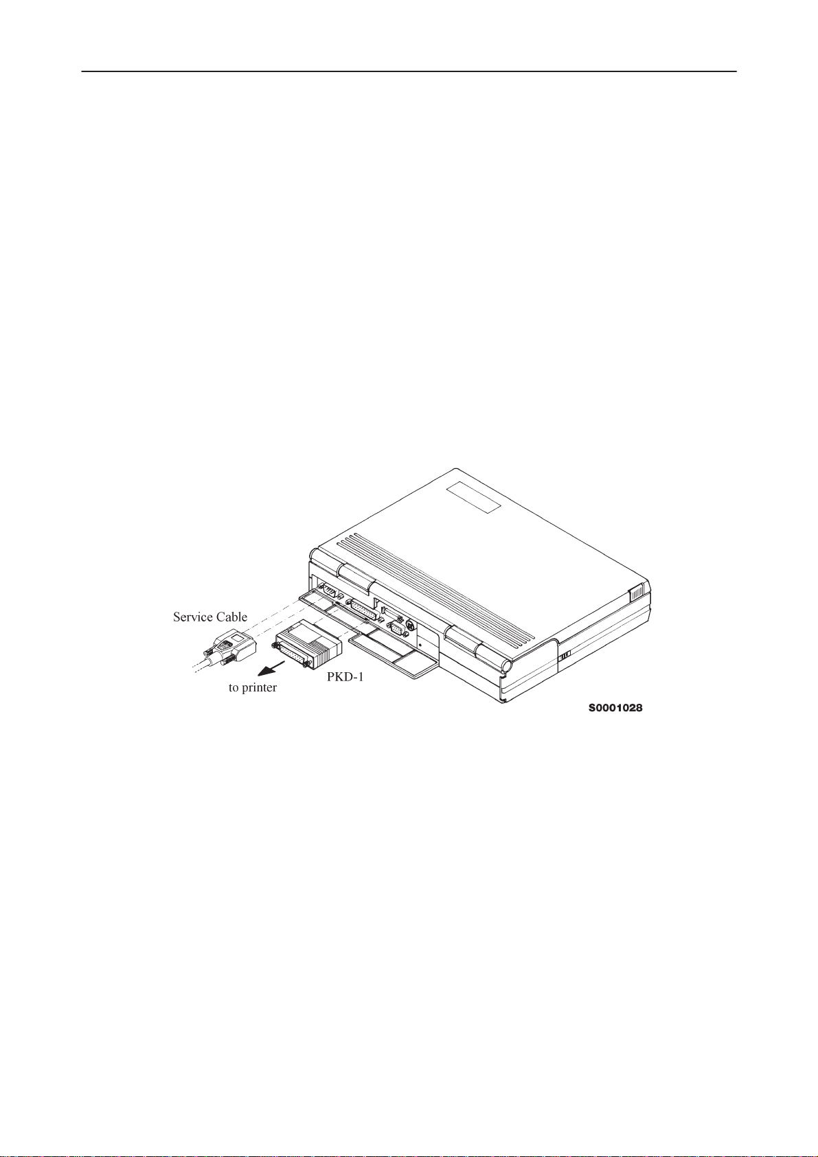
Mechanical Connections
Caution: Ensure that you have switched off the PC and the printer before
making connections !
Caution: Do not connect the PKD–1 to the serial port. This could damage
the PKD–1 !
The software controls the phone via a separate adapter connected to the serial
port of the PC and to the telephone’s M2BUS (DAU–4S and XCM–1).
Attach the protection key PKD–1 to parallel port one (25–pin female D–connector) of the PC. When connecting the PKD–1 to the parallel port be sure that you
insert the PC end of the PKD–1 to the PC (male side). If you use a printer on
parallel port one, place the PKD–1 between the PC and your printer cable.
The PKD–1 should not effect devices working with it. If some errors occur (errors in printing are possible) please try printing without the PKD–1. If printing is
OK without the PKD–1 please contact your dealer. We will offer you a new
PKD–1 in exchange for your old one.
Technical Documentation
6 – 6
Original 09/97
Page 7
PAMS
TFE/TFK–2
Technical Documentation
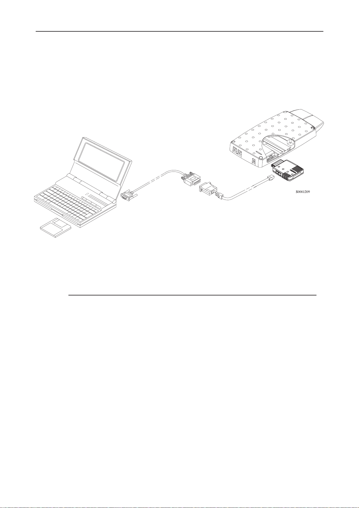
Attach the DAU–2T PC/MBUS adapter to the PC serial port, using an RS–232
9–pin to 25–pin adapter if necessary. Attach one end of the modular cable
XCM–1 to DAU–2T, and the other end to the system connector with the help of
the Service Adapter AFW–2.
Service Software Instructions
Install Procedure
Start the phone by connecting the power supply to TFK–2. Switch PC power on.
To install software, proceed as follows:
1. If WinTesla has already been installed to PC, jump to step 5.
If not, Insert the WinTesla installation disk into drive A of your PC
2. Start the Installation program: select File –> Run from Program
3. Follow the Installation Software instructions.
4. Restart windows.
5. Remember to install WinTesla at least once before.
Insert the TFE/K–2 DLL installation disk into drive A of your PC.
6. Start Installation program: select File –> Run from Program
7. Follow the Installation Software instructions
manager menu, then type
A:INSTALL
manager menu, then type
A:INSTALL
and press OK button
and press OK button
8. Start WinTesla by double clicking the WinTesla Icon
Original 09/97
6 – 7
Page 8
TFE/TFK–2
PAMS
Service Software Instructions
Technical Documentation
Introduction to Service Software Package User Interface
This chapter gives a short description of the Service Software properties.
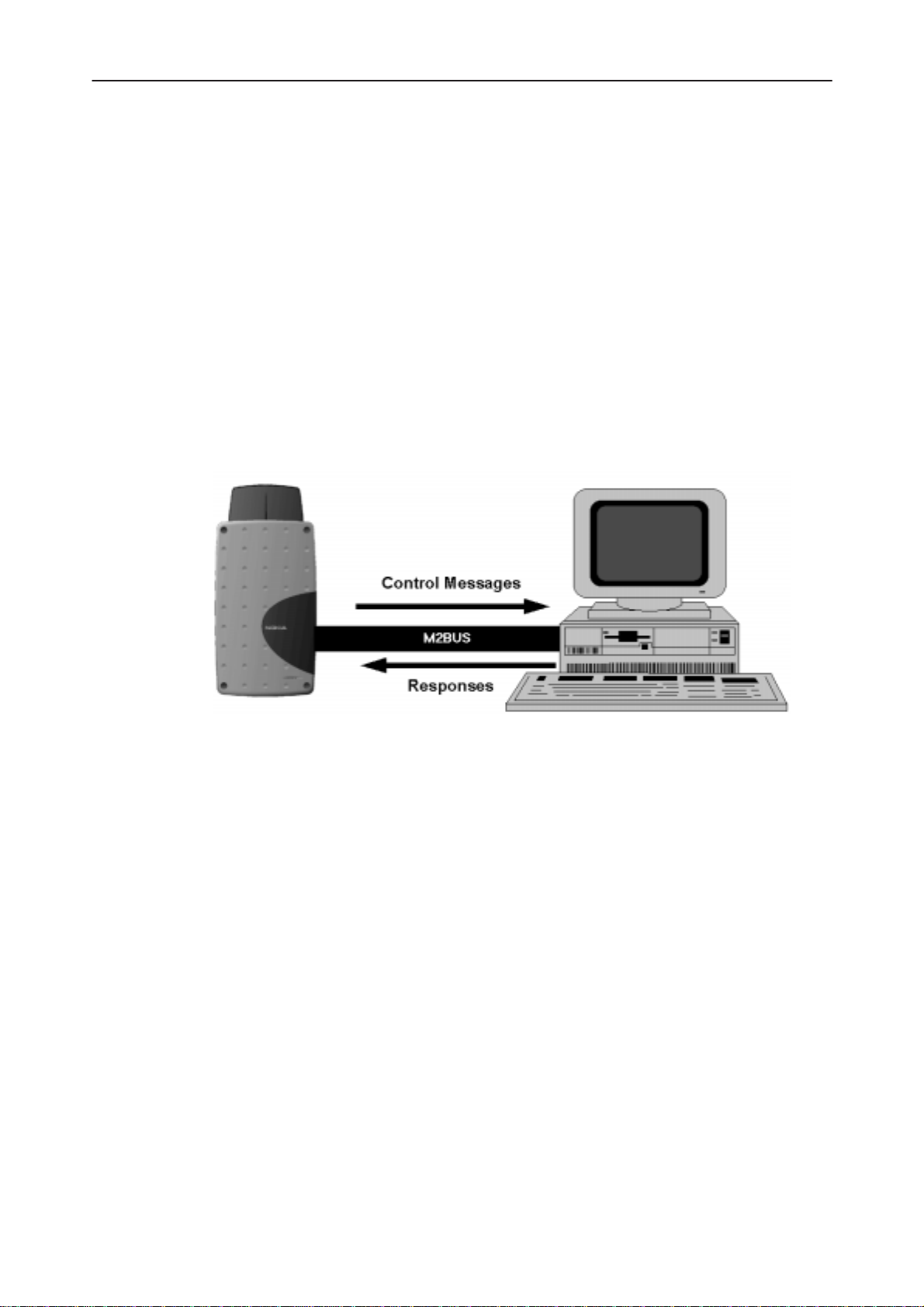
Service Software Hardware Environment
To run the Service Software, a parallel port software protection device (PKD–1)
has to be connected. The user can use the Service Software functions for testing all supported Phone Types. The functions send messages from the PC to
the phone, receives results and show them on the PC display. The messages
are sent via a low level NMP proprietary bus protocol. An example bus is an
M2BUS interface, which needs M2BUS adapter (DAU–2) connected to the PC
RS–232 port and special M2BUS cable.
The recommended minimum hardware standard to run the Service Software
package is any computer which is 386 33Mhz or greater with at least 4 MB of
memory and VGA type display (640x480). This assumes that only the Service
Software package is active, i.e. other Windows packages are not running in the
background.
Note: if the Service Software is to be run on laptops, the power saving feature
MUST be switched off.
Service Software Environment
Service Software user interface is intended for Microsoft Windows 3.1x environment running in enhanced mode. For those who are familiar with Windows environment this application will be easy to use. Detailed information about Windows and application usage can be found from Microsoft Windows Version 3.1
Users Guide chapter one (Windows Basics) and chapter two (Application Basics).
As an ordinary Windows application, the main idea in the user interface is that
selections are made with menus, push buttons and shortcut keys. Selections
6 – 8
Original 09/97
Page 9

PAMS
TFE/TFK–2
Technical Documentation
can be done by using keyboard and/or mouse. When messages from phone
are received, they cause display updating in special display windows. There is
always a status bar displayed at the bottom of the main window which contains
information about current actions.
Service Software Executables
Only one executable is needed – WinTesla. For TFE/K–2 there are two dlls:
– Functionality DLL is TFEK2.DLL
– User Interface DLL is TFEK2EN.DLL.
Command Line Parameters
There are NO command line parameters.
Service Software Instructions
Original 09/97
6 – 9
Page 10

TFE/TFK–2
PAMS
Service Software Instructions
Common Properties of the User Interface
This chapter describes how the User Interface CLF will appear to the user.
The User Interface is capable of being driven without the use of a mouse, as
the service engineer rarely has space on the bench to use a mouse.
Login Dialog box
When the Service Software application is invoked, by clicking the Service Software icon, the Login dialog box will be displayed on the screen.
Technical Documentation
Nokia logo and application name bitmap (–)
Displays Nokia logo and name of the application.
Application version static text (–)
Contains the name and version of the application.
Copyright notice static text (–)
Copyright is informed as: “Nokia Mobile Phones (c) 1996. All Rights Re-
served”.
Login Box edit box (–)
User Login ID edit box, where user enters his/her faultlog user name.
OK button (default key)
User name is stored in memory and dialog box is closed. When the dialog box
is closed, the application starts.
6 – 10
Original 09/97
Page 11

PAMS
TFE/TFK–2
Technical Documentation
Cancel button (ESC)
The dialog box is closed and application is started, but the Faultlog feature is
disabled.
Help button (F1)
Activates the Windows Help application and displays context sensitive Help.
Main Window
The application supports a
service software interface will present a
pearance.
Note: MDI is to allow for future expansion, e.g. R&D features.
Service Software Instructions
Multiple Document Interface (MDI).
Single Document Interface (SDI)
However, the
ap-
Title bar
The
title bar
A title bar contains the following elements:
• Application Control–menu button
• Maximize button
• Minimize button
• Name of the application
• Restore button
The properties of these elements and their usage is described in Ref 3– Microsoft Windows Version 3.1 Users Guide chapter one (Windows Basics) and
chapter two (Application Basics).
is located at the top of the window.
Original 09/97
6 – 11
Page 12

TFE/TFK–2
PAMS
Service Software Instructions
Menu bar
The
menu bar
The menu bar is a dynamic element and is dependent on the dongle type fitted
and whether a phone is connected.
Underlined characters in menu names and options indicates that the menu
selection can be done by pressing
be selected by activating menu bar with
row–keys to highlight desired menu. In that case, selection is done by pressing
Enter
.
Refer to section 3.3 – Menu bar for a detailed description of the contents of the
menu bar.
Menus can also be selected by using the mouse as described in Ref 3– Microsoft Windows Version 3.1 Users Guide.
Status bar
The
status bar
The status bar contains information about the menu selections and events.
The left area of the status bar describes actions of menu items as the user
uses the arrow keys to navigate through menus.
is below the title bar and contains all available menu selections.
is displayed at the bottom of the Service Software main window.
Technical Documentation
Alt+ underlined character
Alt
– key ( or
F10
key ) and using ar-
. Options can also
The status bar texts are explained in detailed in each of command’s description.
The right areas of the status bar indicate which of the following keys are
latched down:
Indicator Description
USER Entered Login ID.
CAP The Caps Lock key is latched down.
NUM The Num Lock key is latched down.
SCRL The Scroll Lock key is latched down.
Tool bar
The
tool bar
document.
is NOT defined and will not be implemented until specified by this
6 – 12
Original 09/97
Page 13

PAMS
TFE/TFK–2
Technical Documentation
Menu Bar
The Service Software package will have two menu bar configurations. The first,
is an abbreviated version that contains the minimum number of menus that allows package configurations when a phone is NOT connected. The second, is
described below:
The menu bar MUST only contain the follow menus for the Service Software
package when a phone is connected:
roduct*
• P
onfigure*
• C
• Tuning
• Testing
• Software
ealer
• D
• View
• Help*
* – always displayed, even if no phone is connected.
A menu is broken down into sections that are indicated with menu separators.
Each sections identifies a logical difference from itself and other sections, i.e.
between transmitter and receiver. Any items that are required to be added to a
menu lists will be added on the bottom of the appropriate menu section list. If a
new item is to be added which is common to two or more phone types, then
that menu item will become a common menu item.
Service Software Instructions
Product
The menu lists will use the Microsoft [...] symbol after an item name to indicate
that selecting that item will NOT initiate an operation immediately, i.e. a dialog
box will be displayed for the user to select options or type in data and press an
OK button before the operation is performed.
The Product menu MUST contain the following menu items:
• N
ew Ctrl+R
• Open...
• Close
• I
nitialize
• N
ormal Mode F5
ocal Mode Shift+F5
• L
•F
aultlog
• A
ctivate Faultlog... F9
• E
dit Faultlog...
• E
xit Alt+F4
Original 09/97
6 – 13
Page 14

TFE/TFK–2
PAMS
Service Software Instructions
Configure
The Configure menu MUST contain the following menu items:
• O
ptions...
• D
irectories...
aultlog...
• F
• Phone Type Specific configuration items (where applicable)
Tuning
The Tuning menu MUST contain the following menu sections:
• Receiver
• Transmitter
• Voltages
• Phone Type Specific tuning items (where applicable)
Technical Documentation
Testing
An example T
• A
FC...
SI (AGC)...
• R
• Tx
Power...
• Tx IQ
• B
• C
• LCD
• L
Additional menu items may be added within the sections according to the phone type being tuned, e.g. a Charger tuning menu
item will be added after the Battery tuning item but not in the
Transmitter tuning section.
The Testing menu MUST contain the following menu sections:
...
attery...
harger A/D...
A/D...
CD Display...
uning menu is shown below:
6 – 14
• Quick Tests
• Digital
• User Interface Flexi
• Transmitter
• Receiver
Original 09/97
Page 15

PAMS
TFE/TFK–2
Technical Documentation
• Automatic Tests
• Phone Type Specific testing items (where applicable)
An example Te
• Q
uick Testing (RF)...
• S
elf Tests...
• A
DC Readings
• Au
dio
• D
isplay...
• C
all Simulation...
• N
oise Sensitivity...
Additional menu items may be added within the sections
according to the phone type being tested.
Where a menu item consists of more than one test; a pop–up menu may be
added to identify the appropriate sub–tests, e.g. there may be two receiver
tests required for a particular phone type (Bit Error Rate and RSSI Monitoring).
These will be shown as a pop–up from the Receiver menu item.
Service Software Instructions
sting menu is shown below:
Software
The Software menu MUST contain the following menu sections:
• Phone Identity/Numbers
• Flashing
• Phone Type Specific software items (where applicable)
An example S
• Phone I
• P
roduct Profile...
• S
tart Up Self–Tests...
• Set Default V
• N
etwork Settings...
• H
W Settings...
• W
arranty State...
• Service Numb
oftware menu is shown below:
dentity
alues...
ers...
Original 09/97
6 – 15
Page 16

TFE/TFK–2
PAMS
Service Software Instructions
Dealer
The Dealer menu MUST contain the following menu sections:
• Phone UI Data Editors
• Phone UI Data Transfer
• Phone Re–Initialization Functions
• Subscriber Data
• Phone Type Specific dealer items (where applicable)
An example D
• Short C
• U
ser Settings
• Set UI Default V
ealer menu is shown below:
ode Memory
View
Technical Documentation
alues
The View menu MUST contain the following sections:
• Service Windows
• Production Windows (where applicable)
• R&D Windows (where applicable)
An example V
• Q
uick RF Info...
• P
hone Identity...
Phone Identity Window
The Phone Identity window should contain, as a minimum, the following data:
• Software Version(s)
• Hardware Version(s)
• Serial Number(s)
• Product Code
iew menu is shown below:
6 – 16
This window will only be used as a display window and therefore will not allow
editing of the displayed data. This window will not contain any controls other
than a scroll bar.
Original 09/97
Page 17

PAMS
TFE/TFK–2
Technical Documentation
Help
The Help menu MUST contain the following menu items:
• I
ndex
• G
eneral Help
• U
sing Help
• A
bout WinTesla
Mouse Cursors
The standard Windows pointer will be used as the mouse cursor.
During time consuming tasks e.g. communication to phone, an hour glass will
be shown informing the user that a task is in progress. The application uses the
hour glass cursor to inform user that application has taken the control and any
actions from user will be ignored.
Service Software Instructions
When a function is initiated, the hour glass will be displayed and when the function has finished the mouse pointer will return to normal.
Reserved Keys
The following Hot keys and Short Cut keys are reserved either as Microsoft
standard keys or as part of the Common Look and Feel specified by this document.
Short Cut Function Keys
Key Description Defined by
F1 Context Sensitive Help Microsoft
F5 Normal Mode NMP
Shift+F5 Local Mode NMP
F9 Activate Faultlog NMP
F10 Goto Menu Bar Microsoft
Ctrl+F4 Close Active Window Microsoft
Alt Hot Keys
Key Description Defined by
Alt+F4 Exit Active Application Microsoft
Alt+H Help Microsoft
Original 09/97
6 – 17
Page 18

TFE/TFK–2
PAMS
Service Software Instructions
Ctrl Hot Keys
Key Description Defined by
Ctrl+N File – New Microsoft
Ctrl+O F
Ctrl+P F
Ctrl+R P
Shift Hot Keys
Key Description Defined by
Shift+F5 Local Mode NMP
Key Strokes
Key Description Defined by
Technical Documentation
ile – Open Microsoft
ile – Print Microsoft
roduct – New NMP
Alt+P Product Menu NMP
Alt+P,N N
Alt+P,O O
Alt+P,C C
Alt+P,I I
Alt+P,I,N N
Alt+P,I,L L
Alt+P,F F
Alt+P,F,A A
Alt+P,F,E E
Alt+P,E E
Alt+C C
Alt+C,O O
Alt+C,D D
Alt+C,F F
ew NMP
pen NMP
lose NMP
nitialize Pop–up NMP
ormal Mode NMP
ocal Mode NMP
aultlog Pop–up NMP
ctivate Faultlog NMP
dit Faultlog NMP
xit Application NMP
onfigure NMP
ption NMP
irectories NMP
aultlog NMP
6 – 18
Alt+T T
Alt+T,A A
Alt+T,R R
Alt+T,X Tx
uning Menu NMP
FC NMP
SSI(AGC) NMP
Power NMP
Original 09/97
Page 19

PAMS
TFE/TFK–2
Technical Documentation
Alt+T,Q Tx I/Q
Alt+E Te
Alt+E+Q Q
Alt+E+R R
Alt+E,S S
Alt+E,A A
Alt+E,F F
Alt+E,U Au
Alt+E,L L
Alt+E,C C
Alt+E,N N
Alt+S S
Alt+S,I Phone I
Alt+S,P P
Service Software Instructions
NMP
sting Menu NMP
uick Testing (RF) NMP
SSI Reading NMP
elf Tests NMP
DC Readings NMP
ield Test Display NMP
dio and Line Adapter NMP
eds NMP
all Simulation NMP
oise Sensitivity NMP
oftware Menu NMP
dentity NMP
roduct Profile NMP
Alt+S,S S
Alt+S,V Set Default V
Alt+S,L L
Alt+S,P P
Alt+S,A A
Alt+D D
Alt+D,C Short C
Alt+D,U U
Alt+D,Q Q
Alt+D,V Reset UI Default V
Alt+V V
Alt+V,Q Q
Alt+V,P P
Alt+H H
Alt+H,I I
tart–up Self Tests NMP
alues NMP
n Settings NMP
roduct Profile NMP
utomatic Area Code NMP
ealer Menu NMP
ode Memory NMP
ser Settings NMP
uick Install NMP
iew Menu NMP
uick/RF Info NMP
hone Identity NMP
elp Menu Microsoft
ndex Microsoft
alues NMP
Alt+H,G G
Alt+H,U U
Alt+H,A A
Original 09/97
eneral Help Microsoft
sing Help Microsoft
bout WinTesla Microsoft
6 – 19
Page 20

TFE/TFK–2
PAMS
Service Software Instructions
Help Functions
The Help User Interface will be the standard Windows help tool called WinHelp.
The context sensitive help is activated with F1–key. Help contains also Using
Help, which describes how to use the help facility. Refer to the Windows manual for a detailed description of Windows Help.
Dialog Boxes
The Service Software application uses many different dialog boxes. Dialog
boxes are used to display data and prompt the user for input.
Dialog boxes are opened from menus, or with shortcut keys. Dialog boxes have
different properties, but some features will be common.
All service dialog boxes must be modal, that is, the user will not be able to start
another operation without first closing the present dialog box.
All dialog box will contain the following entities:
– Help button
Technical Documentation
– Title bar
– At least one button other than Help
– Application Control–menu Button
Common Dialog boxes
This sections describes the common dialog boxes to be used in the Service
Software package, and the context in which they will be used.
Note Message Box
When the user has made illegal selection a
be opened and message text is displayed. A message box is also opened when
the program has some information for the user. The size of the dialog box may
vary. An information dialog box is recognized by the !–icon.
Dialog boxes will also contain an OK button and a Help button.
OK button (default key):
note message box
dialog box will
6 – 20
Acknowledge displayed information and continue. The Dialog box is closed after selection.
Help button (Alt+H):
Opens context sensitive help as F1–key does.
Original 09/97
Page 21

PAMS
TFE/TFK–2
Technical Documentation
Query Message Box
Confirmations and questions are asked in
query dialog box is recognized by the ?–icon.
Dialog boxes will also contain a Yes button, a No button, and a Help button.
Yes button (Alt+Y or Y) (default key):
Accepts confirmation or question.
No button (Alt+N or N):
Denies confirmation or question.
Help button (Alt+H):
Opens context sensitive help as F1–key does.
The buttons may also be OK and Cancel. The operation of these buttons are
same as in a Note dialog box.
Service Software Instructions
query message box
dialog box. A
Error Message Box
Error message box dialog boxes use a Stop–icon. When a “Stop”–dialog box is
displayed, current operation is terminated.
The dialog box will include a description of the failed operation, and reason.
Pressing F1 (Help) application opens the appropriate help topic that gives information about recommended actions.
Dialog boxes will also contain an OK button and a Help button.
OK button (default key):
Acknowledge displayed information and terminate current operation. The Dia-
log box is closed after selection.
Help button (Alt+H):
Open context sensitive help as F1–key does.
Original 09/97
6 – 21
Page 22

TFE/TFK–2
PAMS
Service Software Instructions
Custom Dialog Boxes
All custom dialog boxes will contain the predefined buttons as defined in section 3.8 – Buttons. However, it is recognized that features may require additional button types, but the addition of these non–standard buttons should be carefully considered to minimize any inconsistencies between implementations.
The buttons will be positioned down the right–hand side of the dialog boxes.
The default action will be OK, except where that default action could result in
an irretrievable failure.
All tuning dialog boxes that contain tuning results, will display the old tuned
data read from the phone before the tuning was performed, as well as the newly tuned data.
List boxes will be used to display lists of data, such as tuning data, test results
etc.
The use of Radio buttons should be limited and carefully considered. The use
of radios buttons defines the number of possible choices available to the user,
which may be acceptable for one project, but not for another.
Technical Documentation
6 – 22
Original 09/97
Page 23

PAMS
TFE/TFK–2
Technical Documentation
Buttons
All buttons must be the Microsoft style of buttons.
In general, the default button will be the OK button, the Close button or the Yes
button, but this will depend on the context of the dialog box that the button is
associated with.
OK button:
Accept and validate entered settings and values and closes the dialog box. If
the values have not been changed, then no action will be taken. The status bar
will reflect the status. The user should only be queried, if the settings or values
accepted will over–write data that CANNOT be reproduced.
A greyed OK button indicates that settings selected by the user are not acceptable.
Close button:
Closes the current dialog box. Does not send or store anything, and closes the
dialog box. The Close button is only used for dialog boxes that do not set or
change any data.
Service Software Instructions
Cancel button (Esc):
Cancel operation. Does not send or store anything, and closes the dialog box.
A greyed Cancel button indicates that it is not possible to quit from this dialog
box.
Yes button (ALT+Y or Y):
Replies Yes to a question asked of the user.
No button (ALT+N or N):
Replies No to a question asked of the user.
Help button (ALT+H):
Open context sensitive help as F1–key does.
Reporting Status
The status bar will be used to report the present status to the user. When a feature is initiated, the status bar will be updated with a brief description of the
function. The status bar will also be updated at key points in a time consuming
function.
If an error is to be reported to the user, it will be displayed in the status bar as
well as displayed in a common error dialog box. This will mean the user is not
delayed from progressing on to the next operation unless an error occurs, in
which case the user will have to acknowledge the error by pressing the OK button.
Original 09/97
6 – 23
Page 24

TFE/TFK–2
PAMS
Service Software Instructions
TFE/K–2 Specific Features
Menu Bar
User instructions for TFE/K–2 specific features are available after installation as
a Windows help file. It can be accessed while using the Service Software as a
context sensitive help function.
With the dialog box open, press F1 or the HELP–button to get help.
Help can also be opened by clicking the tfek2en.hlp file from the directory
where the Service Software has been installed (default c:\wintesla).
Opening help file in Windows 3.1x:
1) Start File Manager
2) Goto directory where the Service Software is installed
3) Double–click the tfek2en.hlp file
Opening help file in Windows 95:
1) Select Start –> Run
2) Type c:\wintesla\tfek2en.hlp
Technical Documentation
or
1) Double–click My Computer
2) Double–click Drive containing service Software (default C:)
3) Double–click wintesla folder
4) Double–click tfek2en.hlp file
6 – 24
Original 09/97
Page 25

PAMS
TFE/TFK–2
Technical Documentation
Appendix 1, Vocabulary
Abbreviation Description
ADC Analog to Digital Converter
AFC Automatic Frequency Control
AFW–1 CAP adapter
AFW–2 Service adapter
AGC Automatic Gain Control
API Application Programming Interface
ASIC Application Specific Integrated Circuit
CLF Common Look and Feel
DATA DATA interface module
DAU–4S M2BUS – RS–232 adapter
DAU–2T RS–232 – M2BUS adapter
Service Software Instructions
DCT2 Digital Core Technology Second Generation
DLL Dynamic Link Library
DSP Digital Signal Processor
EEPROM Memory for adjustment parameters (Electrically Erasable
and Programmable Read Only Memory)
IMEI International Mobile Equipment Identification code
IMSI International Mobile Subscriber Identification code
LA Line Adapter
LED Light Emitting Diode
M2BUS Serial communication bus which can be connected to
accessory devices and test PC
MCU Master Control Unit processor
MDI MCU DSP Interface; message interface via ASIC registers
ME Mobile Equipment
MFC Microsoft Foundation Class library
MS Mobile Station
MTI Message Transfer Interface
PC IBM PS/AT or compatible personal computer
PCBOX Local Net driver SW for PC
PCI Phone Controlling Interface SW for PC
Original 09/97
6 – 25
Page 26

TFE/TFK–2
PAMS
Service Software Instructions
PKD–1 Parrallel port software protection device
RF Radio Frequency parts
RFI Radio Frequency Interface circuit
SW Software
TFE–1 GSM 900 Fixed Wireless terminal
TFE/K–1 GSM 900 / GSM 1800 Fixed Wireless terminal
TFE/K–2 Advanced GSM 900 / GSM 1800 Fixed Wireless terminal
TFK–1 GSM 1800 Fixed Wireless terminal
TX Transmitter
UI User Interface
WLL Fixed Wireless (Wireless Local Loop)
Technical Documentation
6 – 26
Original 09/97
Page 27

PAMS
TFE/TFK–2
Technical Documentation
Service Software Instructions
This page intentionally left blank.
Original 09/97
6 – 27
 Loading...