

Page 1

After Sales Technical Documentation
TFK–1 Series Transceiver
Chapter 2
TECHNICAL
INFORMATION
Original 32/96
Page 2

TFK–1
After Sales
Technical Information
Technical Documentation
CHAPTER 2 – TECHNICAL INFORMATION
Contents
Introduction Page 2–3
Product Selection Page 2–3
Handportable Page 2–3
Product and Module List Page 2–4
Technical Specifications Page 2–5
General Specifications of TFK–1 Series Transceiver Page 2–5
Electrical Specifications Page 2–6
Transceiver General Features Page 2–6
Receiver Branch Page 2–6
Transmitter Branch Page 2–7
Page 2–2
Original 32/96
Page 3
After Sales
TFK–1
Technical Documentation
Introduction
This chapter contains a list of products/modules together with their associated
order codes, and details of the performance specifications for the TFK–1 Series
Transceiver. The performance specifications are split into general, transmitter,
and receiver functions.
Product Selection
Terminal
The TFK–1 is a radio WLL–transceiver unit for the GSM based DCS–1800 network. It is a DSC–1800 power class 1 transceiver providing 11 power levels
with a maximum output power of 1 W.
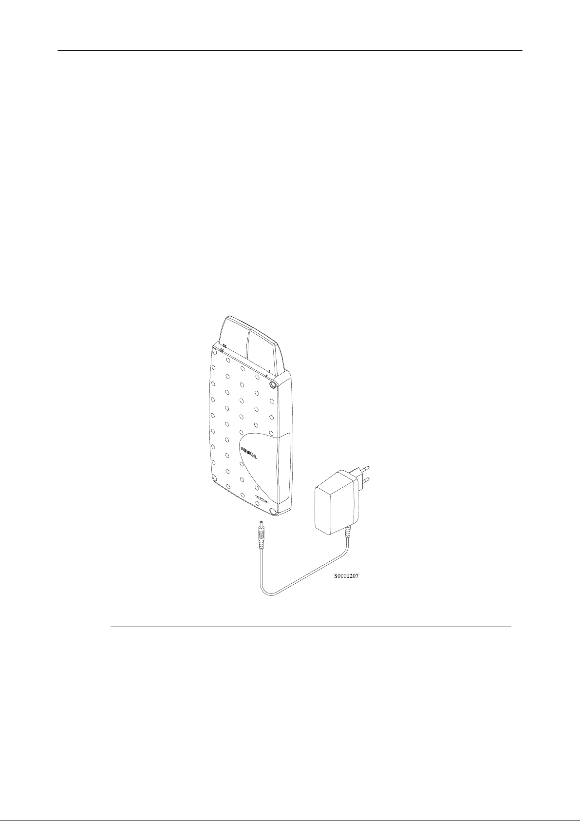
The basic package contains the following products:
Technical Information
3.
1.
2.
Item/name: Type: Product code:
1. DCS–1800 Terminal TFK–1 0630074
2. Power supply (Euro plug) ACW–2 0675123
Power supply (US plug) ACW–2P 0675135
Power supply (UK plug) ACW–2X 0675136
3. Antenna AHA–1F 0660129
Original 32/96
Page 2–3
Page 4

TFK–1
After Sales
Technical Information
Product and Module List
Unit/type: Product code: Module code:
Transceiver TFK–1 See variant
Power Supply ACW–2 (Euro plug) 0675123
Power Supply ACW–2P (US plug) 0675135
Power Supply ACW–2X (UK plug) 0675136
Antenna AHA–1F 0660129
Technical Documentation
Appendixes
Page 2–4
Original 32/96
Page 5

After Sales
TFK–1
Technical Documentation
Technical Specifications
General Specifications of TFK–1 Series Transceiver
Temperature range
Operating time (with BBW–1)
talk time
standby time
Battery voltage
Nominal current consumption
idle mode
call mode,
Dimensions (h x w x d)
transceiver
Weight
+5C to +40C
2.5 h
10 h
6.8 V
300 mA
700...1400 mA
213 x 121 x 28 mm
Technical Information
transceiver
800 g
Original 32/96
Page 2–5
Page 6

TFK–1
After Sales
Technical Information
Electrical Specifications
Transceiver General Features
Cellular system PCN
RX frequency band 1805 ... 1880 MHz
TX frequency band 1710 ... 1785 MHz
Output power 0,01 ... 1 W
Duplex spacing 95 MHz
Number of RF channels 374
Channel spacing 200 kHz
Number of TX power levels 11
Sensitivity –100 dBm/ S/N>8 dB
Frequency error <+/– 0.1 ppm
RMS phase error < +/– 5.0
Peak phase error < +/– 20.0
Technical Documentation
o
o
Receiver Branch
Frequency band
Type
IFs
3 dB bandwidth ±
Reference noise bandwidth
Sensitivity
AGC dynamic range
Receiver gain
Front end IF gain control range
Input dynamic range
2nd IF gain control range
Gain relative accuracy in receiving
band
Gain relative accuracy on channel ±
1805...1880 MHz
linear, three IF
313, 87 and 13 MHz
100 kHz
270 kHz
–100 dBm RX channel input
I/Q S/N ratio > 8 dB
81 dB, typ.
81 dB, typ.
24 dB
–100...–10 dBm
57 dB
±
1.5 dB
0.4 dB
Page 2–6
Original 32/96
Page 7

After Sales
TFK–1
Technical Documentation
Transmitter Branch
TX frequency band
Type
Intermediate frequency
Gain control range
Power class
Output power
Power levels
Frequency error < ±
RMS phase error < ±
Peak phase error < ±
1710...1785 MHz
Upconversion
200 MHz
20 dB
1
0.01 .... 1W
11
0.1 ppm
5.0
°
20.0
°
Technical Information
Original 32/96
Page 2–7
Page 8

TFK–1
After Sales
Technical Information
Technical Documentation
This page intentionally left blank.
Page 2–8
Original 32/96
 Loading...