

Page 1

Programmes After Market Services (P.A.M.S.)
Technical Documentation
NME–2A SeriesTransceivers
Tuning Instructions
Issue 2 05/2000
Page 2

NME–2A
Tuning Instructions
P.A.M.S.
Technical Documentation
AMENDMENT RECORD SHEET
Amendment
Number
Date Inserted By Comments
08/97 Original
Issue 2 02/2000 OJuntune ARS added
Fig. p.7, p.8 updated
Page 2
Issue 2 05/2000
Page 3

P.A.M.S.
NME–2A
Technical Documentation
Tuning Instructions
Contents
General 5. . . . . . . . . . . . . . . . . . . . . . . . . . . . . . . . . . . . . . . . . . . . . . . . . . . . . . . . .
Required Equipment 5. . . . . . . . . . . . . . . . . . . . . . . . . . . . . . . . . . . . . . . . . . . . . .
Equipment Setup 6. . . . . . . . . . . . . . . . . . . . . . . . . . . . . . . . . . . . . . . . . . . . . . . . .
Starting The Program 9. . . . . . . . . . . . . . . . . . . . . . . . . . . . . . . . . . . . . . . . . . . . .
Starting options for PCLocals service software 9. . . . . . . . . . . . . . . . . . . .
Tuning Steps 10. . . . . . . . . . . . . . . . . . . . . . . . . . . . . . . . . . . . . . . . . . . . . . . . . . . .
1. RSSI Reference Signal Level Storage 10. . . . . . . . . . . . . . . . . . . . . . . . .
2. AFC Diagram Storage 10. . . . . . . . . . . . . . . . . . . . . . . . . . . . . . . . . . . . . . .
3. I/Q Modulator Amplitude Balance and Phase Shift Tuning 11. . . . . . . .
4. Tuning of Transmitter Power Levels 13. . . . . . . . . . . . . . . . . . . . . . . . . . .
Page No
Issue 2 05/2000
Page 3
Page 4

NME–2A
Tuning Instructions
Technical Documentation
List of Figures
Figure 1. Equipment setup with Audio Test Box -Tuning 7. . . . . . . . . . . . . .
Figure 2. Equipment setup without Audio Test Box - Tuning 8. . . . . . . . . .
Figure 3. Amplitude Balance /Phase Shift Graph 11. . . . . . . . . . . . . . . . . . .
P.A.M.S.
Page No
Page 4
Issue 2 05/2000
Page 5

P.A.M.S.
NME–2A
Technical Documentation
General
Most of the tuning are done with help of the PCLocals software. The
PCLocals program turns the phone into the Locals mode, in which the
phone can be outwardly controlled via the M2BUS interface.
Tuning is based on the PCLocals software communicating with the D/A
and A/D converters of the phone. In some instances the phone processor
will also calculate the required correction parameter.
The tuning values of the phone reside on the EEPROM. The contents of
the EEPROM can be read by the PCLocals program and saved as a file.
This is advisable when there is need to retain that information, e.g. in view
of replacement of the circuit. The program also enables writing the default
parameters on the EEPROM, in which case all tuning steps should be
carried out.
If a repair has been carried out on the RF section of a system module
then
the appropriate tunings should be performed as described in the following
section and using the on-screen help menus as a guide. Spare system
modules will be delivered pre-tuned from the factory and will not require
re-tuning.
N.B. During tuning, proceed as follows:
Tuning Instructions
– Take care not to damage sensitive measuring instruments with exces-
sive RF power.
– Carry out all tuning steps in the shortest possible time to avoid exces-
sive heating of RF units.
– Perform all tuning steps in the order presented.
– Never try to mask a fault by tuning it out!
Required Equipment
– PC/AT computer with PCLocals software; see different PCLocals
Instructions for instructions on installation and use.
– M2BUS adapter DAU–2 and other service accessories; see equipment
setup pictures.
– Multimeter or DVM.
– Power supply 13.2 V and minimum 5 A current capability.
– GSM radio telephone test station or separate measuring equipment as
follows:
– frequency counter (±1 ppm)
– RF generator
– pulse power meter
– spectrum analyzer
– attenuator and branching unit
Issue 2 05/2000
Page 5
Page 6

NME–2A
Tuning Instructions
Equipment Setup
Caution: Make sure that you have switched off the PC and the printer
before making connections!
Caution: Do not connect the PKD-1 key to the serial port. You may
damage your PKD-1!
Attach the protection key PKD-1 to parallel port one (25-pin female
D-connector) of the PC. When connecting the PKD-1 to the parallel port
be sure that you insert the PC end of the PKD-1 to the PC (male side). If
you use a printer on parallel port one, place the PKD-1 between the PC
and your printer cable.
To set up equipment, connect the M2BUS adapter to the serial port
(RS-232) of the computer. In case you are using a 9-pin serial port
(normal with an AT set) use the mating adapter supplied with the M2BUS
adapter.
P.A.M.S.
Technical Documentation
Attach one end of the DKH-1 modular cable to the DAU-2 PC/M2BUS
adapter and the other end to the service box. Connect one end of another
modular cable also to the service box and the other end to the phone’s
system cable.
Then connect handset’s spiral cable to the service box as well.
For audio testing connect the coaxial cables as follows:
- Connect both coaxial BNC - BNC cables to the connectors of service box
marked as MIC and EAR.
- Attach EAR line of coaxial cable to AF INPUT of test equipment.
- Attach MIC line of coaxial cable to MOD GEN OUTPUT of test
equipment.
The RF cable should be connected between the RF connector of the
phone and the RF connector of the test equipment.
Last, connect the system cable to the phone as well as power supply and
switch the power on to all equipments.
Page 6
Issue 2 05/2000
Page 7
P.A.M.S.
NME–2A
Technical Documentation
Tuning Instructions
NME-2A
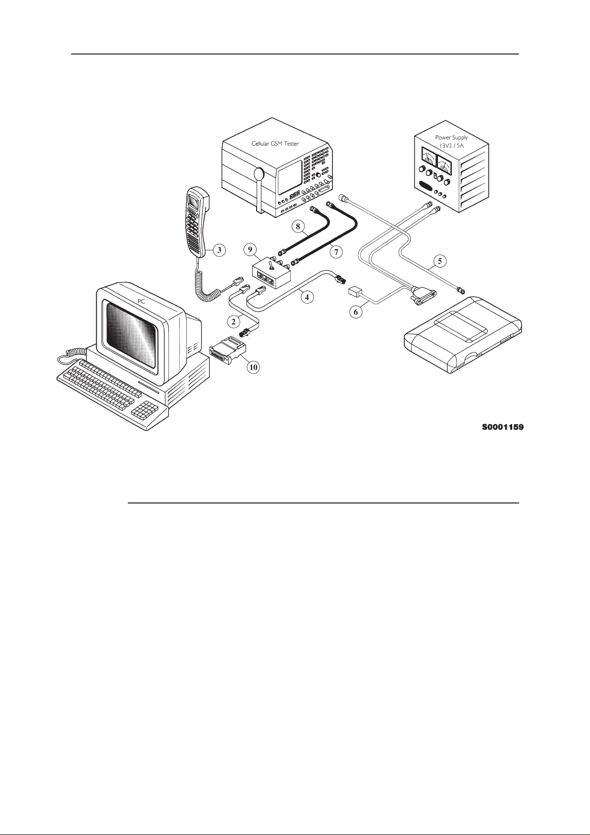
Figure 1. Equipment setup with Audio Test Box -Tuning
Item: Service accessory: Type Product code:
2,4 Modular cable DKH-1 9780084
3 Handset, HSE-6XA 0640098
5 Coaxial cable mini UHF-BNC not supplied
6 System Cable SCM-1 0730066
7, 8 Coaxial cable, BNC - BNC not supplied
9 Audio Test Box JBA-3 0694044
10 PC/M2BUS adapter DAU-2 0750006
- RS-232 adapter (9 pin to 25 pin) 4626170
- Software protection key PKD-1 0750018
- Service Software diskette 3.5” 0774028
- Service Software diskette 5.25” 0774031
Issue 2 05/2000
Page 7
Page 8

NME–2A
Tuning Instructions
P.A.M.S.
Technical Documentation
NME-2A
Figure 2. Equipment setup without Audio Test Box - Tuning
Item: Service accessory: Type Product code:
1 Service cable, DKH-5 0730038
3 Handset, HSE-6XA 0640098
5 Coaxial cable, mini UHF - BNC not supplied
6 System Cable SCM-1 0730066
10 PC/M2BUS adapter DAU-2 0750006
- RS-232 adapter (9 pin to 25 pin) 4626170
- Software protection key PKD-1 0750018
- Service Software diskette 3.5” 0774028
- Service Software diskette 5.25” 0774031
Page 8
Issue 2 05/2000
Page 9

P.A.M.S.
NME–2A
Technical Documentation
Starting The Program
The program is delivered on a diskette and is copy protected with a
dongle. The program can also be installed on the hard disk, which is
recommendable to obtain a maximum data access rate. In case you want
to store the program to the hard disk, proceed according to instructions
given in PCLocals installation manual.
The program is started with the command:
Enter
NME2SERV
The program can be set up work with different serial ports or display
types.
(or PCLSTART
Starting options for PCLocals service software
The program is started by entering the following command:
Enter
)
Tuning Instructions
NME2SERV
For more information about how to operate the PCLocals software, refer
to booklet PCLocals Software Instructions.
Issue 2 05/2000
Page 9
Page 10

NME–2A
Tuning Instructions
Tuning Steps
1. RSSI Reference Signal Level Storage
Reference value for the received signal strength meter are program tuned.
RSSI reference signal level programming:
– Start the service software and go to ”Main” menu.
P.A.M.S.
Technical Documentation
– Select ”Phone mode” and select local mode with
– Select ”Testing and Adjustments” menu and press
– Select ”Adjustments” menu and press
– Connect RF generator to antenna connector at 947.06771 MHz.
– Adjust signal generator level to –57 dBm + cable attenuation.
– Select ”RSSI Calibration” and press
– RSSI offset value should be within 37...49 dB.
– AGC calibration values (Compensation Term) should be
below ±2.0dB.
– Press
– Store the value to the EEPROM with
Esc
key.
2. AFC Diagram Storage
This tuning is used to calibrate the automatic frequency control range.
AFC tuning:
Enter
Enter
Y
key.
Enter
key.
Enter
.
.
.
Page 10
– Set RF generator frequency 947.06771 MHz at level –57 dBm.
– Select adjustments menu option ”AFC Diagram” and press
– Check that ” Cont mode channel” is 60
– The measurement result should be;
• Low over –22 kHz (< –10 kHz)
• Middle ±1.5 kHz (depends on generator frequency accuracy)
• High below +22 kHz (> 10 kHz)
– Press
Esc
key and store with Y key.
Enter
Issue 2 05/2000
Page 11

P.A.M.S.
NME–2A
Technical Documentation
Tuning Instructions
3. I/Q Modulator Amplitude Balance and Phase Shift Tuning
The purpose of this tuning operation is to adjust the I/Q modulator d.c.
offsets and the I/Q modulator amplitude balance and phase shift.
I/Q modulator d.c. offsets, amplitude balance and phase shift tuning:
– Connect spectrum analyzer (with attenuator if needed) to phone an-
tenna connector.
– Select adjustment menu option ”TX I/Q Tuning” and press
– Press
Y.
– Check that TX power level is level 10, Cont. mode channel is 60 and
TX data type is 1.
– Adjust spectrum analyzer centre frequency to 902 MHz, Span 200
kHz, Res BW 10 kHz, Video BW 1 kHz and Sweep time 0.5 s.
–67.71 kHz +67.71 kHz
CHF
Enter
.
D.C. offset
tunings:
Set this value
to minimum
> 30 dB
> 35 dB
Amplitude &
phase difference:
Set this value
to minimum
Figure 3. Amplitude Balance /Phase Shift Graph
– Select option ”TX I d.c. offset” and press
Enter
.
– Adjust the level of centre frequency (CHF signal) to minimum by vary-
ing D/A converter value with + and – keys.
– The amplitude difference between CHF–67.7 kHz and CHF should be
>30 dB.
– When value is OK press
– Select option ”TX Q d.c. offset” and press
– Adjust the level of signal CHF to minimum by varying D/A converter
value with + and – keys.
Issue 2 05/2000
Esc
.
Enter
.
Page 11
Page 12

NME–2A
Tuning Instructions
P.A.M.S.
Technical Documentation
– When value is OK press
– If the change when adjusting TX I was small, then repeat the Whole
adjustment.
– Select option ”TX I and Q d.c. offset” and press
– Adjust the level of signal CHF to minimum by varying D/A converter
value with + and – keys.
– When value is OK press
– Select option ”Tune Amplitude Difference” and press
– Adjust the level of signal CHF+67.7 kHz (902.06771 MHz) to minimum
by varying D/A converter value with + and – keys.
– The amplitude difference between CHF+67.7 kHz and CHF–67 kHz
should be >35 dB.
– When value is OK press
– Select option ”Tune Phase Difference” and press
– Adjust the level of signal CHF+67.7 kHz to minimum by varying D/A
converter value with + and – keys.
– When value is OK press
Esc
Esc
Esc
Esc
.
Enter
.
.
Enter
.
.
Enter
.
.
– If the change in ”Tune amplitude difference” was small, then repeat the
adjustment again from ”Tune amplitude difference”.
– Press
Esc
key and store new values with Y key.
Page 12
Issue 2 05/2000
Page 13

P.A.M.S.
NME–2A
Technical Documentation
4. Tuning of Transmitter Power Levels
This adjustment loads the power levels of the phone transmitter into the
EEPROM. When doing this, a pulse power meter or spectrum analyzer
must be used.
Note: Before adjusting the power levels, you must be sure the test
equipment have a measuring uncertainty less than
desired levels.
Power levels programming:
– Connect pulse power meter or spectrum analyzer to antenna connec-
tor.
– Check that continuous mode channel 60.
– Select adjustments menu option ”TX Power Tuning” and press
Y
– Press
– Start at Low–Powerlevel 15
the DA step (don’t tune it with the co–efficient !)
.
. Use F9 and F10 to tune the output with
Tuning Instructions
±
1 dB at
Enter
.
Secondly adjust power level 10 and finally level 2. To tune level 10
and 2, use the +/– keys. To change power levels, use up/down keys.
Power
level
2 39
3 37
4 35
5 33
6 31
7 29
8 27
9 25
10 23
11 21
12 19
13 17
Tuning P
(13.2 V, CH60)
tune! Pwr coef
tune! pwr coef
OUT
/dBm
14 15
15 13
– Press F3 to calculate all other levels.
– Once all TX levels are OK, press
PROM with pressing
Issue 2 05/2000
tune! D/A step
Y
.
Esc
and store readings in phone EE-
Page 13
Page 14

NME–2A
Tuning Instructions
P.A.M.S.
Technical Documentation
This page intentionally left blank.
Page 14
Issue 2 05/2000
 Loading...