

Page 1

After Sales Technical Documentation
NHE/K–5/6
SERVICE SOFTWARE
INSTRUCTIONS
Original 05/97
NMP Part No. 0275074
Page 2

NHE/K–5/6 Service Software Instructions
AMENDMENT RECORD SHEET
After Sales
Technical Documentation
Amendment
Number
Date Inserted By Comments
Page 2
Original 05/97
Page 3

After Sales
Technical Documentation
NHE/K–5/6 Service Software Instructions
NHE/K–5/6 SERVICE SOFTWARE INSTRUCTIONS
Contents
Introduction Page 6. . . . . . . . . . . . . . . . . . . . . . . . . . . . . . . . . . . . . . . . . . . .
General Page 6. . . . . . . . . . . . . . . . . . . . . . . . . . . . . . . . . . . . . . . . . . . . .
Minimum Required Servicing Equipment Page 6. . . . . . . . . . . . . . . . .
Mechanical Connections Page 7. . . . . . . . . . . . . . . . . . . . . . . . . . . . . .
Start Up Procedure Page 8. . . . . . . . . . . . . . . . . . . . . . . . . . . . . . . . . . .
Introduction to Service Software Package User Interface Page 9. . . . .
Service Software/Hardware Enviroment Page 9. . . . . . . . . . . . . . . . .
Service Software Enviroment Page 9. . . . . . . . . . . . . . . . . . . . . . . . . .
Service Software Executables Page 10. . . . . . . . . . . . . . . . . . . . . . .
Command Line Parameters Page 10. . . . . . . . . . . . . . . . . . . . . . . . .
Common Properties of the User Interface Page 11. . . . . . . . . . . . . . . . . .
Login Dialog Page 11. . . . . . . . . . . . . . . . . . . . . . . . . . . . . . . . . . . . . . . . .
Main Window Page 12. . . . . . . . . . . . . . . . . . . . . . . . . . . . . . . . . . . . . . . .
Menu Bar Page 14. . . . . . . . . . . . . . . . . . . . . . . . . . . . . . . . . . . . . . . . . . . .
Product Page 14. . . . . . . . . . . . . . . . . . . . . . . . . . . . . . . . . . . . . . . . . . .
Configure Page 15. . . . . . . . . . . . . . . . . . . . . . . . . . . . . . . . . . . . . . . . .
Tuning Page 15. . . . . . . . . . . . . . . . . . . . . . . . . . . . . . . . . . . . . . . . . . . .
Testing Page 15. . . . . . . . . . . . . . . . . . . . . . . . . . . . . . . . . . . . . . . . . . . .
Software Page 16. . . . . . . . . . . . . . . . . . . . . . . . . . . . . . . . . . . . . . . . . .
Dealer Page 17. . . . . . . . . . . . . . . . . . . . . . . . . . . . . . . . . . . . . . . . . . . .
View Page 17. . . . . . . . . . . . . . . . . . . . . . . . . . . . . . . . . . . . . . . . . . . . . .
Phone Identity Window Page 18. . . . . . . . . . . . . . . . . . . . . . . . . . .
Help Page 18. . . . . . . . . . . . . . . . . . . . . . . . . . . . . . . . . . . . . . . . . . . . . .
Mouse Cursors Page 19. . . . . . . . . . . . . . . . . . . . . . . . . . . . . . . . . . . . . . .
Reserved Keys Page 19. . . . . . . . . . . . . . . . . . . . . . . . . . . . . . . . . . . . . . .
Short Cut Function Keys Page 19. . . . . . . . . . . . . . . . . . . . . . . . . . . .
Alt Hot Keys Page 19. . . . . . . . . . . . . . . . . . . . . . . . . . . . . . . . . . . . . . .
Ctrl Hot Keys Page 19. . . . . . . . . . . . . . . . . . . . . . . . . . . . . . . . . . . . . .
Shift Hot Keys Page 20. . . . . . . . . . . . . . . . . . . . . . . . . . . . . . . . . . . . .
Key Strokes Page 20. . . . . . . . . . . . . . . . . . . . . . . . . . . . . . . . . . . . . . .
Help Functions Page 21. . . . . . . . . . . . . . . . . . . . . . . . . . . . . . . . . . . . . . .
Dialog boxes Page 22. . . . . . . . . . . . . . . . . . . . . . . . . . . . . . . . . . . . . . . . .
Common Dialog boxes Page 22. . . . . . . . . . . . . . . . . . . . . . . . . . . . . .
Note Message Box Page 22. . . . . . . . . . . . . . . . . . . . . . . . . . . . . . .
Query Message Box Page 22. . . . . . . . . . . . . . . . . . . . . . . . . . . . .
Error Message Box Page 23. . . . . . . . . . . . . . . . . . . . . . . . . . . . . .
Custom Dialog boxes Page 24. . . . . . . . . . . . . . . . . . . . . . . . . . . . . . .
Buttons Page 24. . . . . . . . . . . . . . . . . . . . . . . . . . . . . . . . . . . . . . . . . . . . .
Reporting Status Page 25. . . . . . . . . . . . . . . . . . . . . . . . . . . . . . . . . . . . .
Original 05/97
Page 3
Page 4

NHE/K–5/6 Service Software Instructions
NHE/K–5 & NHE/K–6 Specific Features Page 26. . . . . . . . . . . . . . . . . . . .
Menu Bar Page 26. . . . . . . . . . . . . . . . . . . . . . . . . . . . . . . . . . . . . . . . . . . .
Product Page 26. . . . . . . . . . . . . . . . . . . . . . . . . . . . . . . . . . . . . . . . . . .
New command Page 26. . . . . . . . . . . . . . . . . . . . . . . . . . . . . . . . . .
Open... command Page 26. . . . . . . . . . . . . . . . . . . . . . . . . . . . . . . .
Close command Page 26. . . . . . . . . . . . . . . . . . . . . . . . . . . . . . . . .
Initialize command Page 27. . . . . . . . . . . . . . . . . . . . . . . . . . . . . . .
Normal Mode Page 27. . . . . . . . . . . . . . . . . . . . . . . . . . . . . . . . . . . .
Local Mode Page 27. . . . . . . . . . . . . . . . . . . . . . . . . . . . . . . . . . . . .
Faultlog Page 27. . . . . . . . . . . . . . . . . . . . . . . . . . . . . . . . . . . . . . . .
Exit command Page 28. . . . . . . . . . . . . . . . . . . . . . . . . . . . . . . . . . .
Configure Page 29. . . . . . . . . . . . . . . . . . . . . . . . . . . . . . . . . . . . . . . . .
Options... command Page 29. . . . . . . . . . . . . . . . . . . . . . . . . . . . . .
Directories... command Page 29. . . . . . . . . . . . . . . . . . . . . . . . . . .
Faultlog... command Page 30. . . . . . . . . . . . . . . . . . . . . . . . . . . . .
After Sales
Technical Documentation
Tuning Page 31. . . . . . . . . . . . . . . . . . . . . . . . . . . . . . . . . . . . . . . . . . . .
AFC... command Page 31. . . . . . . . . . . . . . . . . . . . . . . . . . . . . . . . .
RSSI (AGC)... command Page 32. . . . . . . . . . . . . . . . . . . . . . . . . .
TX Power... command Page 35. . . . . . . . . . . . . . . . . . . . . . . . . . . .
TX I/Q... command Page 37. . . . . . . . . . . . . . . . . . . . . . . . . . . . . . .
Battery A/D... command Page 39. . . . . . . . . . . . . . . . . . . . . . . . . .
Charger A/D... command Page 40. . . . . . . . . . . . . . . . . . . . . . . . .
LCD A/D... command Page 40. . . . . . . . . . . . . . . . . . . . . . . . . . . . .
LCD Display... command Page 40. . . . . . . . . . . . . . . . . . . . . . . . . .
Testing Page 42. . . . . . . . . . . . . . . . . . . . . . . . . . . . . . . . . . . . . . . . . . . .
Quick Testing (RF)... command Page 42. . . . . . . . . . . . . . . . . . . .
RSSI Reading... command Page 47. . . . . . . . . . . . . . . . . . . . . . . .
Self Tests... command Page 48. . . . . . . . . . . . . . . . . . . . . . . . . . . .
ADC Readings... command Page 50. . . . . . . . . . . . . . . . . . . . . . .
Audio... command Page 51. . . . . . . . . . . . . . . . . . . . . . . . . . . . . . .
Display... command Page 52. . . . . . . . . . . . . . . . . . . . . . . . . . . . . .
Call Simulation.. command Page 53. . . . . . . . . . . . . . . . . . . . . . . .
Noise Sensitivity... command Page 54. . . . . . . . . . . . . . . . . . . . . .
Page 4
Original 05/97
Page 5

After Sales
Technical Documentation
Software Page 56. . . . . . . . . . . . . . . . . . . . . . . . . . . . . . . . . . . . . . . . . .
Phone Identity... command Page 56. . . . . . . . . . . . . . . . . . . . . . . .
Product Profile... command Page 57. . . . . . . . . . . . . . . . . . . . . . .
NHE/K–5 Product Profile Settings Page 58. . . . . . . . . . . . . . . . . .
NHE/K–6 Product Profile Settings Page 58. . . . . . . . . . . . . . . . . .
Start Up Self–tests... command Page 59. . . . . . . . . . . . . . . . . . . .
Set Default Values... command Page 60. . . . . . . . . . . . . . . . . . . .
Network Settings... command Page 61. . . . . . . . . . . . . . . . . . . . .
Warranty State... command Page 62. . . . . . . . . . . . . . . . . . . . . . .
Service Numbers... command Page 63. . . . . . . . . . . . . . . . . . . . .
Flash Phone... command Page 64. . . . . . . . . . . . . . . . . . . . . . . . .
Dealer Page 65. . . . . . . . . . . . . . . . . . . . . . . . . . . . . . . . . . . . . . . . . . . .
Short Code Memory... command Page 65. . . . . . . . . . . . . . . . . . .
User Settings... command Page 66. . . . . . . . . . . . . . . . . . . . . . . . .
SCM & User Settings... command Page 68. . . . . . . . . . . . . . . . . .
Set UI/DEV Default Values... command Page 69. . . . . . . . . . . . .
NHE/K–5/6 Service Software Instructions
View Page 70. . . . . . . . . . . . . . . . . . . . . . . . . . . . . . . . . . . . . . . . . . . . . .
Quick/RF Info... command Page 70. . . . . . . . . . . . . . . . . . . . . . . .
Phone Identity... command Page 71. . . . . . . . . . . . . . . . . . . . . . . .
Help Page 72. . . . . . . . . . . . . . . . . . . . . . . . . . . . . . . . . . . . . . . . . . . . . .
Index command Page 72. . . . . . . . . . . . . . . . . . . . . . . . . . . . . . . . .
General help command Page 72. . . . . . . . . . . . . . . . . . . . . . . . . . .
Using Help command Page 72. . . . . . . . . . . . . . . . . . . . . . . . . . . .
About... command Page 72. . . . . . . . . . . . . . . . . . . . . . . . . . . . . . .
Initialization File Page 73. . . . . . . . . . . . . . . . . . . . . . . . . . . . . . . . . . . . . .
Appendix 1, Vocabulary Page 74. . . . . . . . . . . . . . . . . . . . . . . . . . . . . . . . . .
Original 05/97
Page 5
Page 6

NHE/K–5/6 Service Software Instructions
Introduction
General
The NHE/K–5 NHE/K–6 Service Software is specially designed to facilitate the
servicing of sixth generation cellular telephones.
The software can be used to control the phone according to the user’s requirements merely by entering commands via the keyboard or mouse of a PC connected to the phone.
This section refers to the Service Software Version 2.5.
NMP After Sales will notify service personnel about future upgrades via Technical Bulletins. Software upgrades will be available from your local NMP outlet.
Minimum Required Servicing Equipment
– Computer: Intel 386/33 MHz or compatible with one unused serial port
(COM1 or COM2*), one parallel port (LPT1), hard disk recommended.
After Sales
Technical Documentation
– Memory: 4 MB or more
– Operating System: DOS Version 5 & Microsoft Windows 3.11 or later
– Display: VGA based display (640 x 480)
– PC Locals program: for 3.5” disk (product code: 0774034)
– Software Protection Key PKD–1 (product code 0750018)
– M2BUS interface cable DAU–4S (product code 0730057)
Page 6
*)
Note: A number of PC’s of an older generation use the Intel, National Semiconductor, or
United Microelectronics IC 8250 as the serial port UART. This is a comparatively
inefficient circuit for current purposes and does not necessarily support the
M2BUS adapter at 9600 baud. The newer UART’s NS16450 and NS16550AF of
National Semiconductor offer solutions for these problems.
Original 05/97
Page 7
After Sales
Technical Documentation
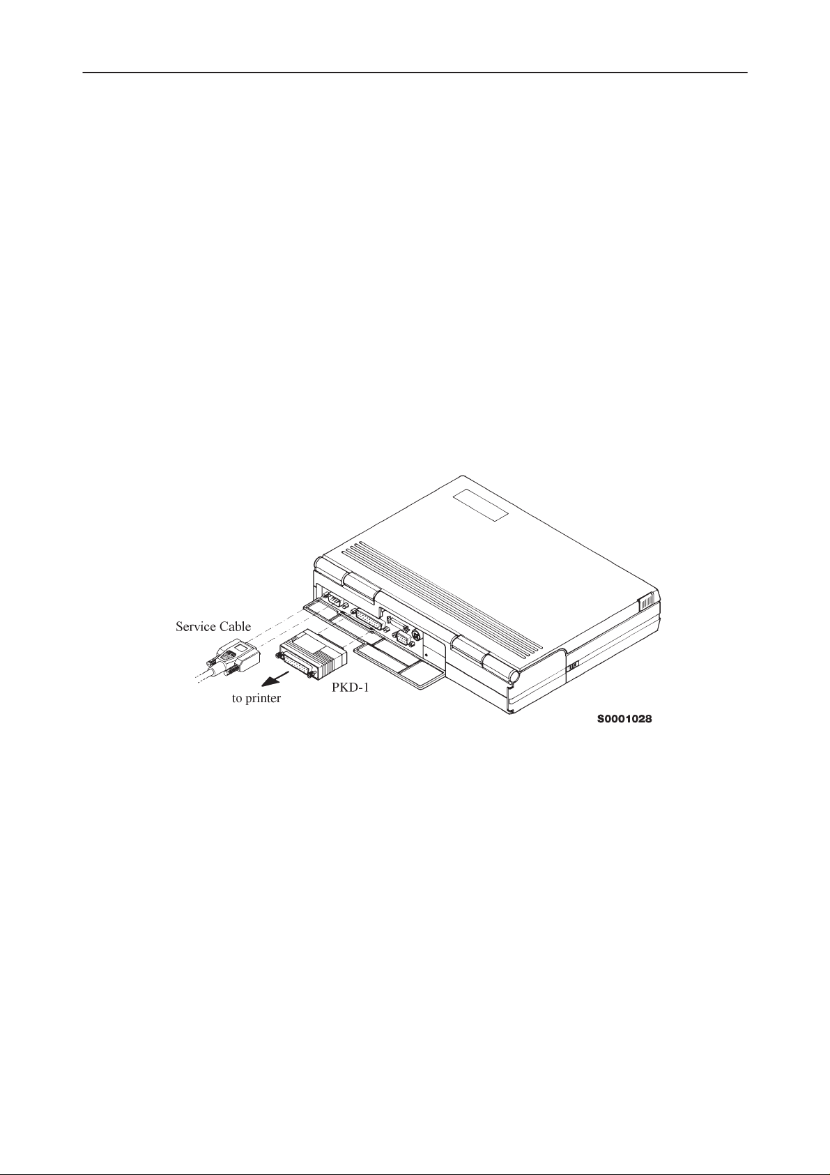
Mechanical Connections
Caution: Ensure that you have switched off the PC and the printer before
making connections !
Caution: Do not connect the PKD–1 to the serial port. This could damage
the PKD–1 !
The software controls the phone via a separate adapter connected to the serial
port of the PC and to the telephone’s M2BUS (DAU–4S and XCM–1).
Attach the protection key PKD–1 to parallel port one (25–pin female D–connector) of the PC. When connecting the PKD–1 to the parallel port be sure that you
insert the PC end of the PKD–1 to the PC (male side). If you use a printer on
parallel port one, place the PKD–1 between the PC and your printer cable.
The PKD–1 should not effect devices working with it. If some errors occur (errors in printing are possible) please try printing without the PKD–1. If printing is
OK without the PKD–1 please contact your dealer. We will offer you a new
PKD–1 in exchange for your old one.
NHE/K–5/6 Service Software Instructions
Original 05/97
Page 7
Page 8
NHE/K–5/6 Service Software Instructions
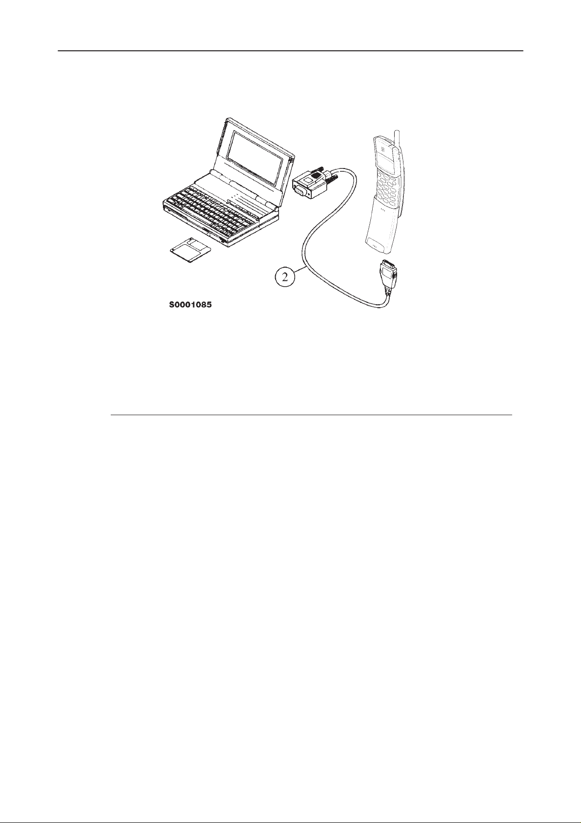
Attach one end of the M2BUS interface cable, DAU–4S (2), to the PC serial
port and the other end to the bottom connector of the phone.
After Sales
Technical Documentation
Start Up Procedure
Start the phone by pressing the power–on button of the handset. Switch PC
power on.
To installing software, proceed as follows:
1. Insert Service Software disk into
drive A of your PC
2. Start Windows: type
3. Start Installing program: select
4. Follow Installation Software
instructions
WIN
and press
File –> Run
menu, then type
OK
press
button
Enter
from Program Manager
A:INSTALL
and
Page 8
Original 05/97
Page 9
After Sales
Technical Documentation
NHE/K–5/6 Service Software Instructions
Introduction to Service Software Package User Interface
This chapter gives a short description of the Service Software properties.
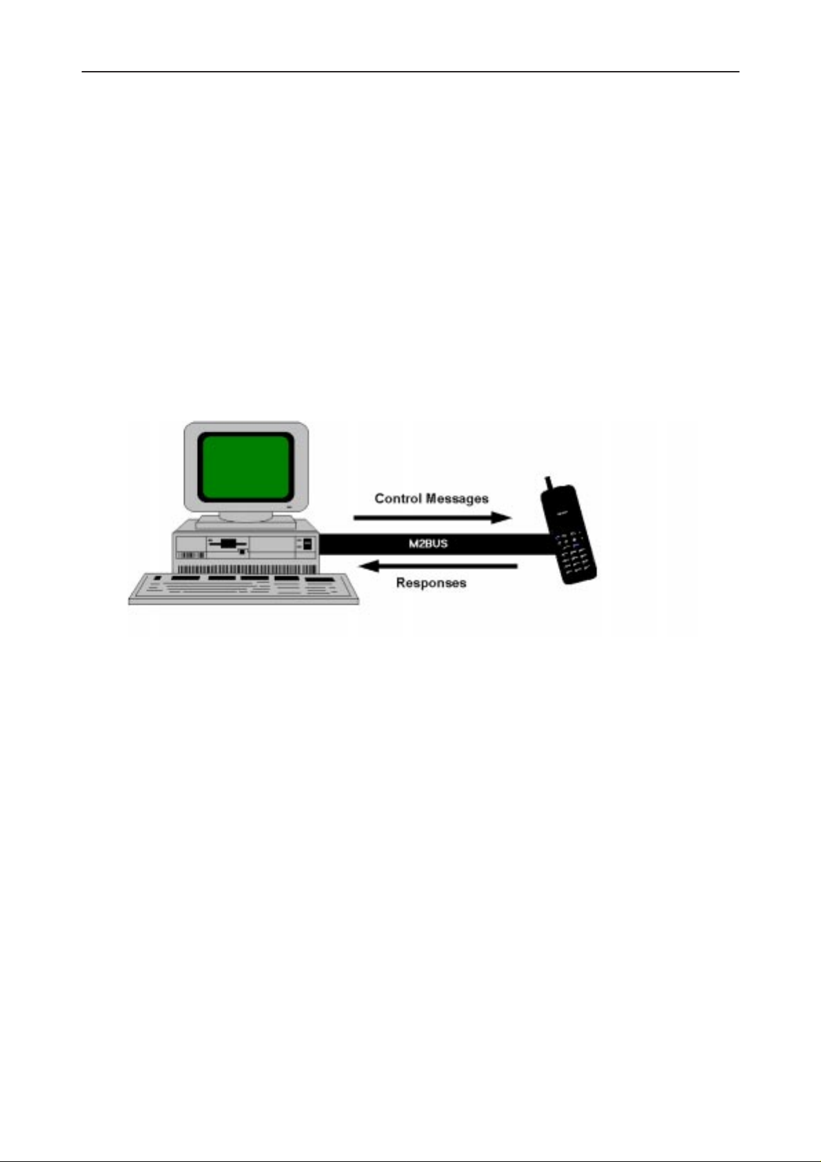
Service Software/Hardware Enviroment
To run the Service Software, a parallel port software protection device (PKD–1)
has to be connected. The user can use the Service Software functions for testing all supported Phone Types. The functions send messages from the PC to
the phone, receives results and show them on the PC display. The messages
are sent via a low level NMP proprietary bus protocol. An example bus is an
M2BUS interface, which needs M2BUS adapter (DAU–2) connected to the PC
RS–232 port and special M2BUS cable.
The recommended minimum hardware standard to run the Service Software
package is any computer which is 386 33Mhz or greater with at least 4 MB of
memory and VGA type display (640x480). This assumes that only the Service
Software package is active, i.e. other Windows packages are not running in the
background.
Note: if the Service Software is to be run on a laptop, the power saving feature
MUST be switched off.
Service Software Enviroment
Service Software user interface is intended for Microsoft Windows 3.1x environment running in enhanced mode. For those who are familiar with Windows environment this application will be easy to use. Detailed information about Windows and application usage can be found from Ref 3– Microsoft Windows
Version 3.1 Users Guide chapter one (Windows Basics) and chapter two (Application Basics).
As an ordinary Windows application, the main idea in the user interface is that
selections are made with menus, push buttons and shortcut keys. Selections
can be done by using keyboard and/or mouse. When messages from phone
Original 05/97
Page 9
Page 10

NHE/K–5/6 Service Software Instructions
are received, they cause display updating in special display windows. There is
always a status bar displayed at the bottom of the main window which contains
information about current actions.
Service Software Executables
Only one executable is needed – WinTesla.
For NHE/K–5/6 there are two DLL’s:
– Functionality DLL is NHEK56.DLL
– User Interface DLL is NHEK56EN.DLL or NHK5EN.DLL
Command Line Parameters
There are NO command line parameters.
After Sales
Technical Documentation
Page 10
Original 05/97
Page 11
After Sales
Technical Documentation
NHE/K–5/6 Service Software Instructions
Common Properties of the User Interface
This chapter describes how the User Interface CLF must appear to the user.
The User Interface MUST be capable of being driven without the use of a
mouse, as the service engineer rarely has space on the bench to use a mouse.
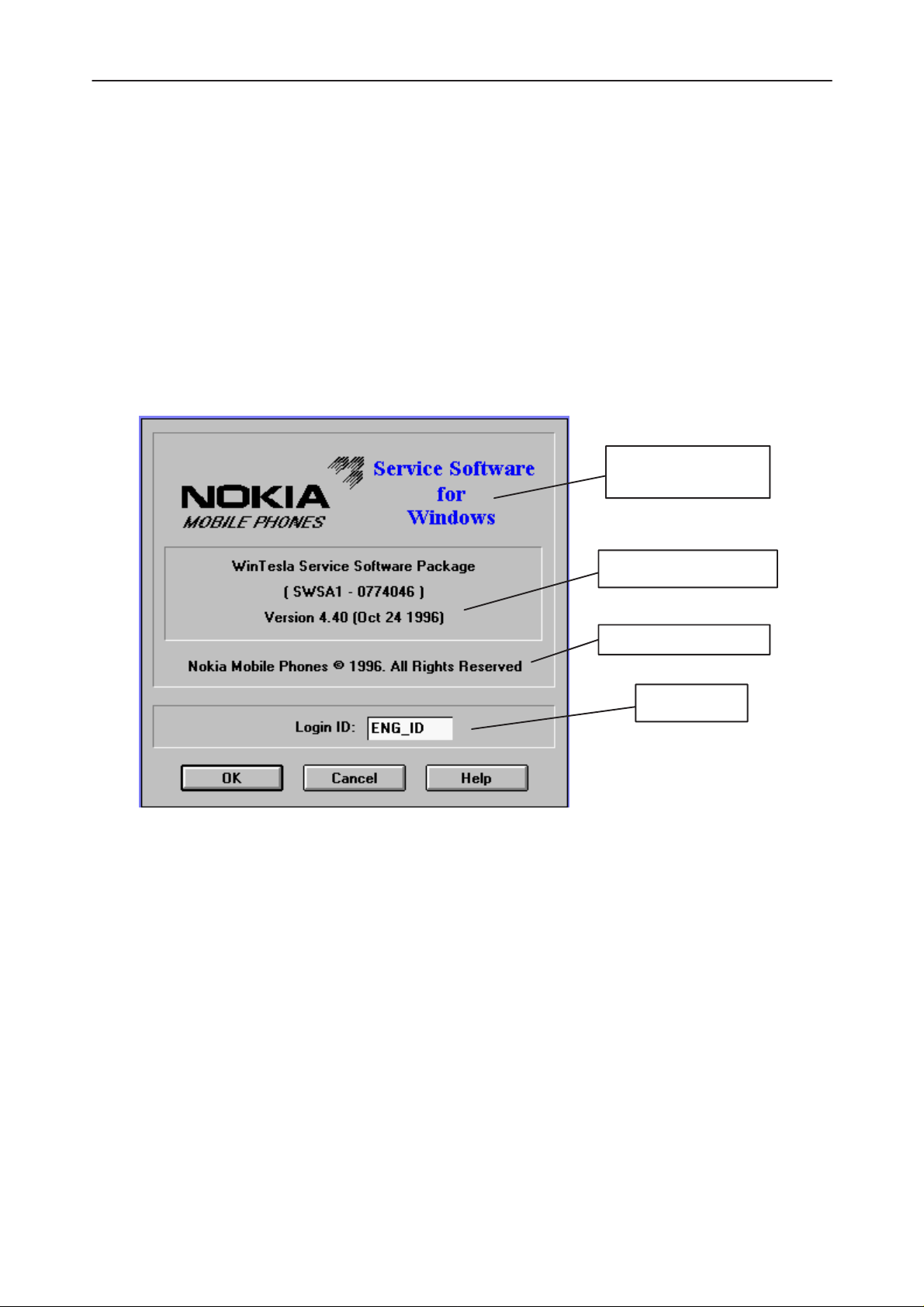
Login Dialog
When the Service Software application is invoked, by checking on the Service
Software icon, the Login dialog box will be displayed on the screen.
Nokia logo and
application name
Nokia logo and application name bitmap (–)
Displays Nokia logo and name of the application.
Application version static text (–)
Contains the name and version of the application.
Copyright notice static text (–)
Copyright is informed as: “Nokia Mobile Phones (c) 1996. All
Rights Reserved”.
Application version
Copyright version
Login box
Login Box edit box (–)
OK button (default key)
Original 05/97
The user Login ID edit box, where the user enters his faultlog user
name. (See Faultlog User Guide)
Page 11
Page 12
NHE/K–5/6 Service Software Instructions
The user name is stored in memory and the dialog box is closed.
When the dialog box is closed, the application starts.
Cancel button (ESC)
The Dialog box is closed and application is started, but the Faultlog
feature is disabled.
Help button (F1)
Activates the Windows Help application and displays context sensitive Help.
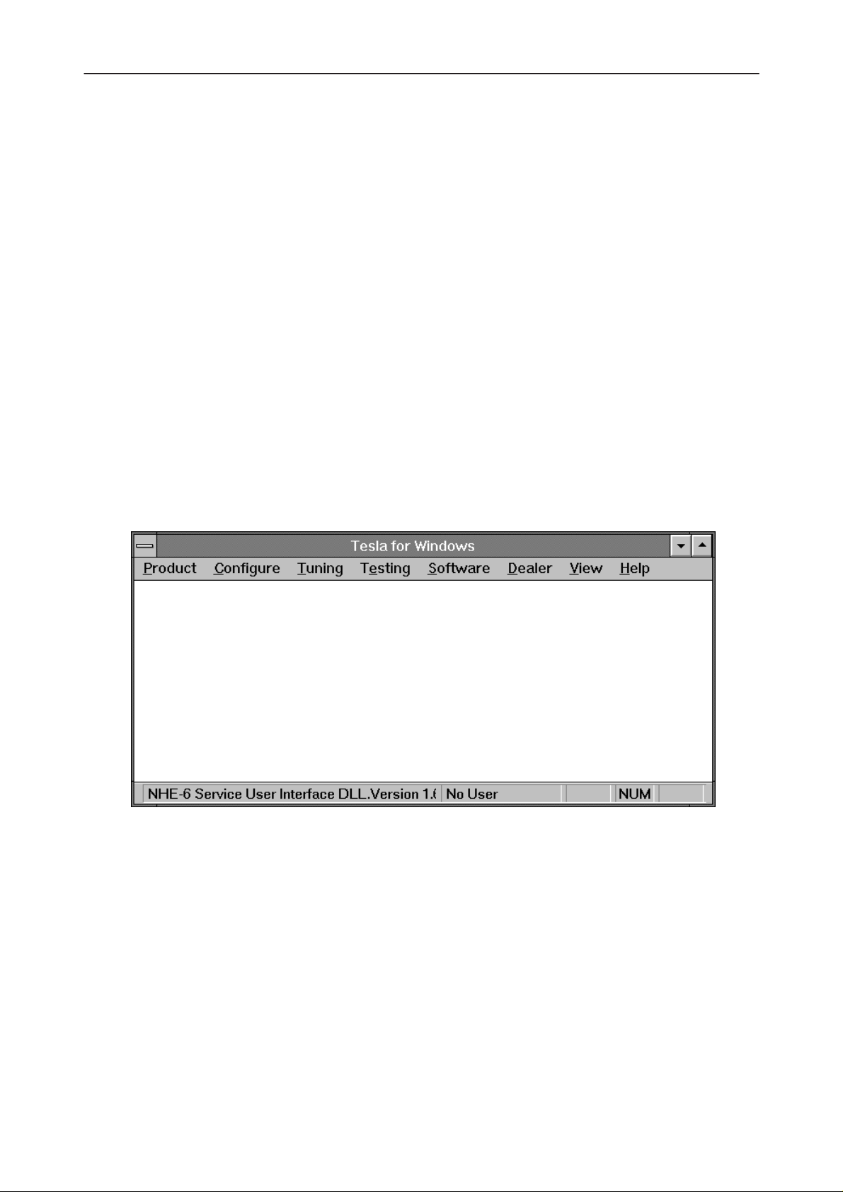
Main Window
After Sales
Technical Documentation
The application supports a
service software interface will present a
pearance.
Note: MDI is to allow for future expansion, e.g. R&D features.
Multiple Document Interface (MDI).
Single Document Interface (SDI)
However, the
ap-
Page 12
Title bar
The
title bar
A title bar contains the following elements:
• Application Control–menu button
• Maximise button
• Minimise button
• Name of the application
• Restore button
The properties of these elements and their usage is described in Ref 3– Microsoft Windows Version 3.1 Users Guide chapter one (Windows Basics) and
chapter two (Application Basics).
is located at the top of the window.
Original 05/97
Page 13

After Sales
Technical Documentation
Menu bar
The
menu bar
The menu bar is a dynamic element and is dependent on the dongle type fitted,
and whether a phone is connected.
Underlined characters in menu names and options indicates that the menu
selection can be done by pressing
be selected by activating menu bar with
row–keys to highlight the desired menu. In that case, selection is done by
pressing
Menus can also be selected by using the mouse as described in Ref 3–Microsoft Windows Version 3.1 Users Guide
Status bar
The
The status bar contains information about the menu selections and events.
Enter
status bar
NHE/K–5/6 Service Software Instructions
is below the title bar and contains all available menu selections.
Alt+ underlined character
Alt
– key ( or
.
is displayed at the bottom of the Service Software main window.
F10
. Options can also
key ) and using ar-
The left area of the status bar describes the actions of menu items as the user
uses the arrow keys to navigate through menus.
The status bar texts are explained in detailed in each of command’s description.
The right areas of the status bar indicate which of the following keys are
latched down:
Indicator Description
USER Entered Login ID.
CAP The Caps Lock key is latched down.
NUM The Num Lock key is latched down.
SCRL The Scroll Lock key is latched down.
Tool bar
The
tool bar
document.
is NOT defined and will not be implemented until specified by this
Original 05/97
Page 13
Page 14
NHE/K–5/6 Service Software Instructions
Menu Bar
The Service Software package will have two menu bar configurations. The first,
is an abbreviated version that contains the minimum number of menus that allows package configurations when a phone is NOT connected. The second is
described below:
The menu bar MUST only contain the follow menus for the Service Software
package when a phone is connected:
roduct*
• P
• C
onfigure*
• T
uning
• Te
sting
• S
oftware
• D
ealer
After Sales
Technical Documentation
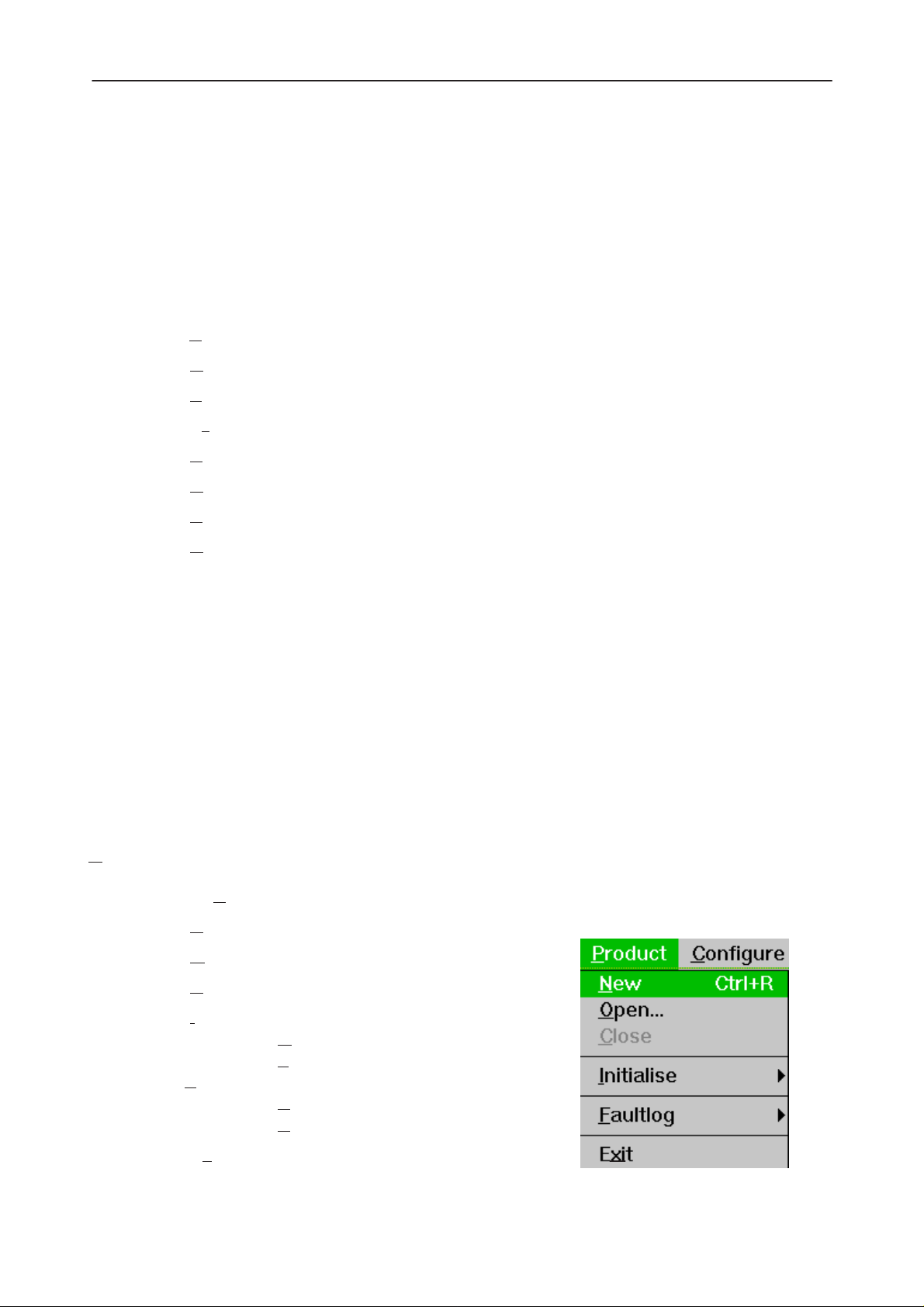
Product
• V
iew
• H
elp*
* – always displayed, even if no phone is connected.
A menu is broken down into sections that are indicated with menu separators.
Each sections identifies a logical difference from itself and other sections, i.e.
between transmitter and receiver. Any items that are required to be added to a
menu lists will be added on the bottom of the appropriate menu section list. If a
new item is to be added which is common to two or more phone types, then
that menu item will become a common menu item.
The menu lists will use the Microsoft [...] symbol after an item name to indicate
that selecting that item will NOT initiate an operation immediately, i.e. a dialog
box will be displayed for the user to select options or type in data and press the
OK button before the operation is performed.
The Product menu contains the following menu items:
• N
ew Ctrl+R
• O
pen...
Page 14
lose
• C
• I
nitialize
• Normal Mode F5
• Local Mode Shift+F5
aultlog
•F
• Activate Faultlog... F9
• Edit Faultlog...
• Ex
it Alt+F4
Original 05/97
Page 15
After Sales
Technical Documentation
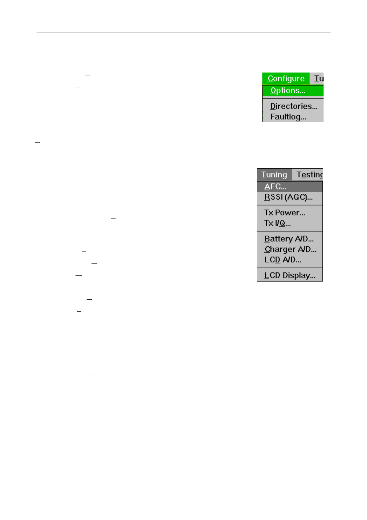
Configure
The Configure menu contains the following menu items:
• O
ptions...
• D
irectories...
• F
aultlog...
• Phone Type Specific configuration items (where applicable)
Tuning
The Tuning menu contains the following menu sections:
• Receiver
• Transmitter
• Voltages
NHE/K–5/6 Service Software Instructions
Testing
• Phone Type Specific tuning items (where applicable)
An example T
• AFC...
• R
SSI (AGC)...
• Tx
Power...
• Tx I/Q
• B
attery A/D
• Charger A/D...
• LCD
• L
Additional menu items may be added within the sections according to the
phone type being tuned, e.g. a Charger tuning menu item will be added after
the Battery tuning item, but not in the Transmitter tuning section.
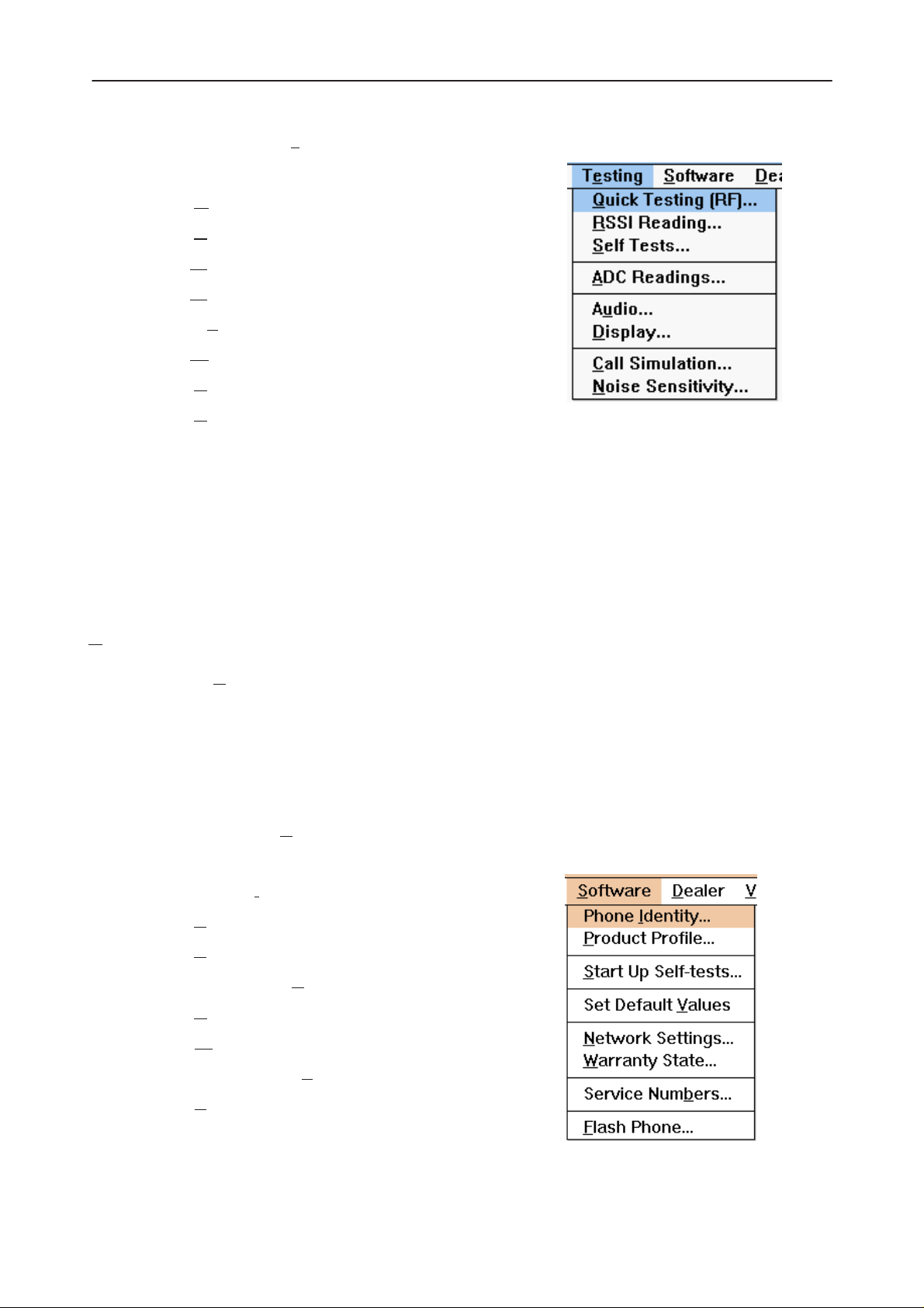
The Testing menu contains the following menu sections:
A/D...
CD Display...
uning menu is shown below:
...
• Quick Tests
• Digital
• User Interface Flexi
• Transmitter
• Receiver
• Automatic Tests
• Phone Type Specific testing items (where applicable)
Original 05/97
Page 15
Page 16
NHE/K–5/6 Service Software Instructions
After Sales
Technical Documentation
An example Te
• Q
uick Testing (RF)...
• R
SSI Reading ...
• S
elf Tests
• A
DC Readings
• Au
dio
• D
isplay
• C
all Simulation...
• N
oise Sensitivity...
Additional menu items may be added within the sections according to the
phone type being tested.
Where a menu item consists of more than one test, a pop–up menu may be
added to identify the appropriate sub–tests, e.g. there may be two receiver
tests required for a particular phone type (Bit Error Rate and RSSI Monitoring).
These will be shown as a popup from the Receiver menu item.
sting menu is shown below:
Software
The Software menu contains the following menu sections:
• Phone Identity/Numbers
• Flashing
• Phone Type Specific software items (where applicable)
An example S
• Phone I
• P
roduct Profile...
• S
tart Up Self–tests...
• Set Default V
• N
etwork Settings...
• W
arranty State...
• Service Numb
oftware menu is shown below:
dentity
alues
ers...
Page 16
• F
lash Phone...
Original 05/97
Page 17
After Sales
Technical Documentation
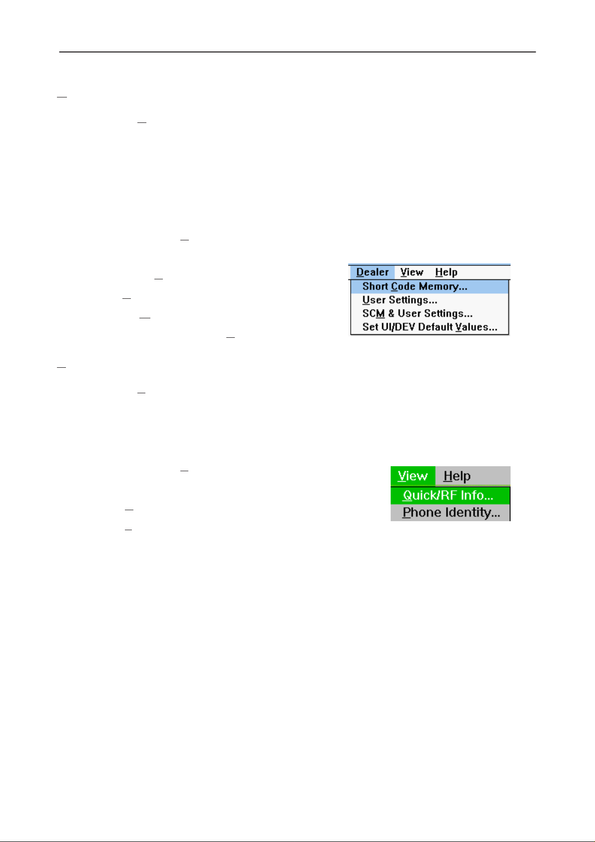
Dealer
The Dealer menu contains the following menu sections:
• Phone UI Data Editors
• Phone UI Data Transfer
• Phone Re–Initialization Functions
• Subscriber Data
• Phone Type Specific dealer items (where applicable)
NHE/K–5/6 Service Software Instructions
View
An example D
• Short C
• U
ser Settings
• SCM
• Set UI/DEV Default V
The View menu contains the following sections:
• Service Windows
• Production Windows (where applicable)
• R&D Windows (where applicable)
An example V
• Q
& User settings ...
uick/RF Info...
ealer menu is shown below:
ode Memory
alues ...
iew menu is shown below:
• P
Original 05/97
hone Identity...
Page 17
Page 18
NHE/K–5/6 Service Software Instructions
hone Identity Window
P
The Phone Identity window should contain, as a minimum, the following data:
• Software Version(s)
• Hardware Version(s)
• Serial Number(s)
• Product Code
This window will only be used as a display window and therefore will not allow
editing of the displayed data. This window will not contain any controls other
than a scroll bar.
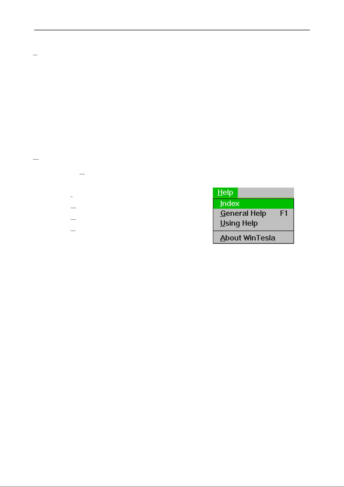
Help
The Help menu contains the following menu items:
After Sales
Technical Documentation
• I
ndex
• G
eneral Help
• U
sing Help
• A
bout WinTesla
Page 18
Original 05/97
Page 19

After Sales
Technical Documentation
Mouse Cursors
The standards Windows pointer will be used as the mouse cursor.
During time consuming tasks e.g. communication to phone, an hour glass will
be shown informing the user that a task is in progress. The application uses the
hour glass cursor to inform user that the application has taken the control and
any actions from user will be ignored.
When a function is initiated, the hour glass will be displayed and when the function has finished the mouse pointer will return to normal.
Reserved Keys
The following Hot keys and Short Cut keys are reserved either as Microsoft
standard keys or as part of the Common Look and Feel specified by this document.
NHE/K–5/6 Service Software Instructions
Short Cut Function Keys
Key Description Defined by
F1 Context Sensitive Help Microsoft
F5 Normal Mode NMP
Shift+F5 Local Mode NMP
F9 Activate Faultlog NMP
F10 Goto Menu Bar Microsoft
Ctrl+F4 Close Active Window Microsoft
Alt Hot Keys
Key Description Defined by
Alt+F4 Exit Active Application Microsoft
Alt+H Help Microsoft
Ctrl Hot Keys
Key Description Defined by
Ctrl+N File – New Microsoft
Ctrl+O F
Ctrl+P F
Ctrl+R P
Original 05/97
ile – Open Microsoft
ile – Print Microsoft
roduct – New NMP
Page 19
Page 20

NHE/K–5/6 Service Software Instructions
Shift Hot Keys
Key Description Defined by
Shift+F5 Local Mode NMP
Key Strokes
Key Description Defined by
Alt+P Product Menu NMP
After Sales
Technical Documentation
Alt+P,N N
Alt+P,O O
Alt+P,C C
Alt+P,I I
Alt+P,I,N N
Alt+P,I,L L
Alt+P,F F
Alt+P,F,A A
Alt+P,F,E E
Alt+P,E E
Alt+C C
Alt+C,O O
Alt+C,D D
Alt+C,F F
Alt+T T
ew NMP
pen NMP
lose NMP
nitialize Pop–up NMP
ormal Mode NMP
ocal Mode NMP
aultlog Pop–up NMP
ctivate Faultlog NMP
dit Faultlog NMP
xit Application NMP
onfigure NMP
ption NMP
irectories NMP
aultlog NMP
uning Menu NMP
Page 20
Alt+T,A A
Alt+T,R R
Alt+T,X Tx
Alt+T,Q Tx I/Q
Alt+T,B B
Alt+T,C C
Alt+T,D LCD
Alt+T,L L
Alt+E Te
Alt+E,Q Q
Alt+E,R R
FC NMP
SSI(AGC) NMP
Power NMP
attery NMP
harger NMP
A/D NMP
CD Display NMP
sting Menu NMP
uick Testing RF NMP
SSI Reading NMP
NMP
Original 05/97
Page 21

After Sales
Technical Documentation
Alt+E,S Self Tests NMP
NHE/K–5/6 Service Software Instructions
Alt+E,A A
Alt+E,U Au
Alt+E,D D
Alt+E,C C
Alt+E,N N
Alt+S S
Alt+S,I Phone I
Alt+S,P P
Alt+S,S S
Alt+S,V Set Default V
Alt+S,N N
Alt+S,W W
Alt+S,B Service Numb
Alt+S,F F
Alt+D D
DC Readings NMP
dio NMP
isplay NMP
all Simulation NMP
oise Sensitivity NMP
oftware Menu NMP
dentity NMP
roduct Profile NMP
tart–up Self Tests NMP
etwork Settings NMP
arranty State NMP
lash Phone NMP
ealer Menu NMP
alues NMP
ers NMP
Alt+D,C Short C
Alt+D,U U
Alt+D,V Set UI Default V
Alt+V V
Alt+V,Q Q
Alt+V,P P
Alt+H H
Alt+H,I I
Alt+H,G G
Alt+H,U U
Alt+H,A A
Help Functions
The Help User Interface will be the standard Windows help tool called WinHelp.
The context sensitive help is activated with F1–key. Help contains also Using
Help which describes how to use help facility. Refer to the Windows manual for
detailed description on the Windows Help.
ode Memory NMP
ser Settings NMP
alues NMP
iew Menu NMP
uick/RF Info NMP
hone Identity NMP
elp Menu Microsoft
ndex Microsoft
eneral Help Microsoft
sing Help Microsoft
bout WinTesla Microsoft
Original 05/97
Page 21
Page 22

NHE/K–5/6 Service Software Instructions
Dialog boxes
The Service Software application uses many different dialog boxes. Dialog
boxes are used to display data and prompt the user for input.
Dialog boxes are opened from menus or with shortcut keys. Dialog boxes have
different properties but some features are common.
All service dialog boxes must be modal, that is, the user will not be able to start
another operation without first closing the present dialog box.
All dialog boxes will contain the following entities:
– Help button
– Title bar
– At least one button other than Help
– Application Control–menu Button
Common Dialog boxes
After Sales
Technical Documentation
This sections describes the common dialog boxes used in the Service Software package, and the context in which they will be used.
Note Message Box
When the user has made an illegal selection, a
opened and message text is displayed. The message box is also opened when
the program has some information for the user. The size of the dialog box may
vary. An information dialog box is recognized by the !–icon.
The dialog box will also contain an OK button and a Help button.
OK button (default key):
Help button (Alt+H):
Query Message Box
note message box
Acknowledge displayed information and continue. The dialog box is
closed after selection.
Opens context sensitive help as F1–key does.
dialog will be
Page 22
Confirmations and questions are asked in
box is recognized by the ?–icon.
The dialog box will also contain a Yes button, a No button, and a Help button.
a query message box
. A query dialog
Original 05/97
Page 23

After Sales
Technical Documentation
Yes button (Alt+Y or Y) (default key):
Accepts confirmation or question.
No button (Alt+N or N):
Denies confirmation or question.
Help button (Alt+H):
Opens context sensitive help as F1–key does.
The buttons may also be OK and Cancel. The operation of these buttons are
the same as in the Note dialog box.
Error Message Box
Error message dialog boxes use the Stop–icon. When a “Stop”–dialog box is
shown, the current operation is terminated.
The dialog box has a description about the failed operation and reason. Pressing F1 (Help) application opens the appropriate help topic that gives information
about recommended actions.
NHE/K–5/6 Service Software Instructions
The dialog box will also contain an OK button and a Help button.
OK button (default key):
Acknowledges displayed information and terminate current operation. The dialog box is closed after selection.
Help button (Alt+H):
Open context sensitive help as F1–key does.
Original 05/97
Page 23
Page 24

NHE/K–5/6 Service Software Instructions
Custom Dialog boxes
All custom dialog boxes will contain the predefined buttons as defined below in
the section –
tional button types, but the addition of these non–standard buttons should be
carefully considered to minimise any inconsistencies between implementations.
The buttons will be positioned down the right–hand side of the dialog boxes.
The default action will be OK, except where that default action could result in
an irretrievable failure.
All tuning dialogs that contain tuning results, will display the old tuned data read
from the phone before the tuning was performed, as well as the newly tuned
data.
List boxes will be used to display lists of data, such as tuning data, test results
etc.
The use of Radio buttons should be limited and carefully considered. The use
of radio buttons defines the number of possible choices available to the user,
which may be acceptable for one project, but not for another.
Buttons.
However, it is recognised that features may require addi-
After Sales
Technical Documentation
Buttons
All buttons must be the Microsoft style of buttons.
In general, the default button will be the OK button, the Close button or the Yes
button, but this will depend on the context of the dialog box that the button is
associated with.
OK button:
Accepts and validates entered settings and values and closes the
dialog. If the values have not been changed, then no action will be
taken. The status bar will reflect the status. The user should only be
queried, if the settings or values accepted will over–write data that
CAN NOT be reproduced.
A greyed OK button indicates that settings selected by the user are
not acceptable.
Close button:
Closes the current dialog box. Does not send or store anything and
closes the dialog. The Close button is only used for dialogs that do
not set or change any data.
Cancel button (Esc):
Page 24
Cancel operation. Does not send or store anything and closes the
dialog box.
A greyed Cancel button indicates that it is not possible to quit from
this dialog box.
Original 05/97
Page 25

After Sales
Technical Documentation
Yes button (ALT+Y or Y):
Replies Yes to a question asked of the user.
No button (ALT+N or N):
Replies No to a question asked of the user.
Help button (ALT+H):
Opens context sensitive help as F1–key does.
Reporting Status
The status bar will be used to report the present status to the user. When a feature is initiated, the status bar will be updated with a brief description of the
function. The status bar will also be updated at key points in a time consuming
function.
If an error is to be reported to the user, it will be displayed in the status bar as
well as displayed in a common error dialog box. This will mean the user is not
delayed from progressing on to the next operation unless an error occurs, in
which case, the user will have to acknowledge the error by pressing the OK
button.
NHE/K–5/6 Service Software Instructions
Original 05/97
Page 25
Page 26

NHE/K–5/6 Service Software Instructions
NHE/K–5 & NHE/K–6 Specific Features
Menu Bar
The Service Software’s menus adopts the menu structure specified by CLF.
Product
New command
Activation Status Bar Text
Alt, P, N Rescan a new phone
Ctrl+R
This command scans a new product. When phone is found a product specific
functionality module is loaded. If no phone or wrong phone/cellular type is detected, functionality is unloaded and user is informed.
After Sales
Technical Documentation
This function is also started automatically when the application is started. The
user can also specify a regular poll which enables the WinTesla application to
scan the new phone periodically. If the phone is still the same, no changes are
done. If the phone is changed (with same phone type only the serial number is
changed), the phone will be initialized to a normal mode. If the phone is
changed to a different phone type, the current dlls are unloaded and new ones
are loaded for that phone.
The initialization routine checks the phone’s cellular type (GSM/PCN), and if an
unsupported phone is detected, the WinTesla application does not load the dlls.
If quick info view is open, the window will be automatically updated.
If phone identification view is open, the window will be automatically updated.
pen... command
O
Activation Status Bar Text
Alt, P, O Force load phone specific functionality
Enables the user to force load specific phone’s WinTesla dll’s.
Close command
Page 26
Activation Status Bar Text
Alt, P, C Close loaded functionality
Closes loaded functionality and sends reset to phone if dlls are loaded by Open
command.
Original 05/97
Page 27

After Sales
Technical Documentation
Initialize command
Activation Status Bar Text
Alt, P, I –
Opens a submenu which contains the following options:
Normal Mode
Activation Status Bar Text
Alt, P, I, N Initializes phone to normal mode
F5
When normal mode has been activated or program has been started, self–test
results will be asked from MCU. If any fault was found in the tests, an error
message is shown. If normal mode has been set successfully (no self test error
has been found), and paging listening has been started, the used AFC value is
requested from MS.
NHE/K–5/6 Service Software Instructions
ocal Mode
L
aultlog
F
The Initialization routine checks the phone’s cellular type (GSM/PCN) and if an
unsupported phone is detected, the application unloads the dlls.
If phone identification view is open, the window will be automatically updated.
Also if RF Information Window is open it will be updated to quick info view.
Activation Status Bar Text
Alt, P, I, L Initialises phone to local mode
Shift+F5
Selection will change the MS state to
phone is controlled to the local mode so that special actions can be made (for
example RF tunings).
Activation Status Bar Text
Alt, P, F –
local
. When local mode is selected the
Opens a submenu which contains following options:
A
ctivate Faultlog...
Activation Status Bar Text
Alt, P, F, A Activates faultlogging
F9
Original 05/97
Page 27
Page 28

NHE/K–5/6 Service Software Instructions
dit Faultlog...
E
Activation Status Bar Text
Alt, P, F, E Activates faultlog editing
Note! This documentation will be updated as soon as WinTesla integration is ready.
Exit command
Activation Status Bar Text
Alt, P, X Exit application
Alt + F4
Double click the application’s Control menu button:
After Sales
Technical Documentation
This command ends the Service Software session.
Page 28
Original 05/97
Page 29

After Sales
Technical Documentation
Configure
Options... command
Activation Status Bar Text
Alt, C, O Edit Service Software options
The Options dialog box contains the following items:
Language drop down list.
Current password edit box:
New Password edit box:
Retype Password edit box:
User ID edit box.
M2BUS Com Port drop down list.
NHE/K–5/6 Service Software Instructions
Automatic Rescan edit box.
Note! This documentation will be updated as soon as WinTesla integration is ready.
D
irectories... command
Activation Status Bar Text
Alt, C, D Edit directory settings
The Directories dialog box contains the following items:
ID D
ata edit box:
L
ogs edit box:
Fault log file(s) edit box:
Data V
Flash i
B
alidation file(s) edit box:
mages edit box:
low failures edit box:
Note! This documentation will be updated as soon as WinTesla integration is ready.
Original 05/97
Page 29
Page 30

NHE/K–5/6 Service Software Instructions
aultlog... command
F
Activation Status Bar Text
Alt, C, F Edit faultlog settings
The Faultlog dialog box contains the following items:
Fault log enabled/disabled radio buttons:
After Sales
Technical Documentation
Allow M
A
utomatic fault log prompting enabled 1/Disabled 2 radio buttons:
S
tation identity edit box:
Country of R
W
arranty period months edit box / drop down list:
Maximum T
Note! This documentation will be updated as soon as WinTesla integration is ready.
anual Entry enabled/disabled radio buttons:
epair edit box:
ime to repair edit box:
Page 30
Original 05/97
Page 31
After Sales
Technical Documentation
Tuning
The tuning menu offers functions for ME adjustments.
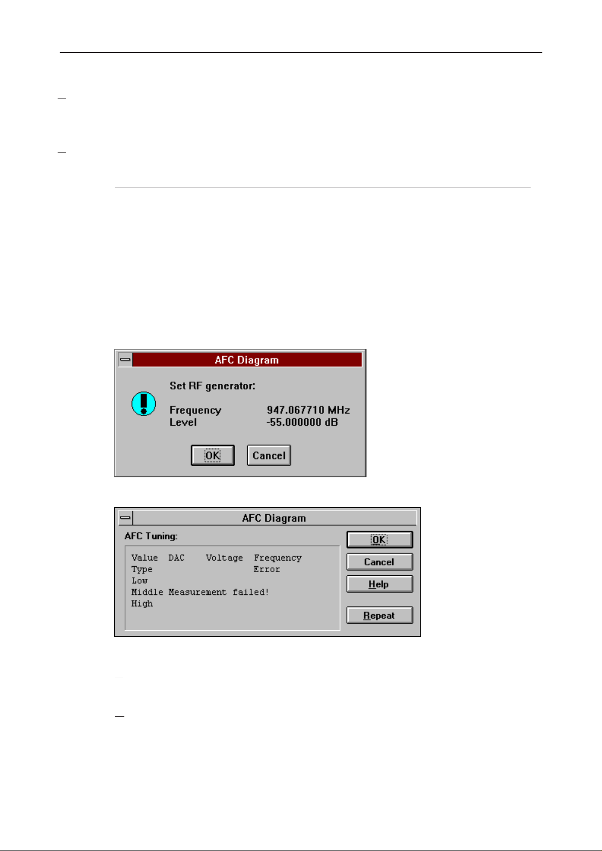
FC... command
A
Activation Status Bar Text
Alt, T, A Open an AFC diagram dialog box
Starts AFC tuning.
The following are automatically selected when this tuning function is activated:
Active Unit = RX
Operation mode = Continuous
Update RF Information window
Before tuning is stared, the user is requested to set signal generator to specified input level (read from .INI file).
NHE/K–5/6 Service Software Instructions
The AFC Diagram dialog box will open when user accepts request:
The AFC Diagram dialog box contains the following items:
R
epeat button (Alt+R):
The measurement can be started again by pressing Repeat button.
O
K button (Alt+O):
The dialog box is closed, and tuning
is saved
to phone.
Original 05/97
Page 31
Page 32

NHE/K–5/6 Service Software Instructions
Cancel button (Esc):
After Sales
Technical Documentation
The D/A converter range (DAC) is from +1023 to –1024 and voltage range is
from 0.3 V to 3.9 V (voltage precision is 0.01 V).
The frequency error range is from –134 kHz to +134 kHz with the precision 0.1
kHz. The rounding is made to the closest value.
After exiting with the Cancel button, the following are reset to the values which
were selected before this adjustment.
The AFC is also reset to its previous value after exiting with the Cancel button.
R
SSI (AGC)... command
Activation Status Bar Text
Alt, T, R Open RSSI Calibration dialog box
Starts RSSI calibration.
Dialog is closed and tuning
Active Unit
Operation mode
Update RF Information window
is not saved
to phone.
The following are automatically selected when this tuning function is activated:
Active Unit = RX
Operation Mode = Continuous
Update RF Information window
The measurement is started automatically when RSSI calibration is entered.
The measurement is done in five steps:
1. The user is requested to set signal generator to low input level (read from
.INI file).
Page 32
2. Measurement with low input level is executed.
Original 05/97
Page 33

After Sales
Technical Documentation
3. The user is requested to set signal generator to high input level (read from
.INI file).
4. Measurement with high input level is executed.
5. The RSSI Calibration dialog box will be updated when previous steps are
done.
NHE/K–5/6 Service Software Instructions
The RSSI Calibration dialog box contains the following items:
Original 05/97
Page 33
Page 34

NHE/K–5/6 Service Software Instructions
GC List box (Alt+A):
A
Gain code DAC can have values from 0 to 1023 and voltage from
0.26 V to 3.86 V (voltage precision is 0.01 V). Note that the needed
input signal level is also shown.
The difference column shows the difference between tuned DAC values and mean straight line calculated from part slopes in dBs (see
/1/). This can be calculated when all measurement results have been
received from phone.
epeat button (Alt+R):
R
The measurement can be started again by pressing this button.
K button (Alt+O):
O
After Sales
Technical Documentation
The dialog box is closed, and tuning
Cancel button (Esc):
The dialog box is closed and tuning
When calibration is ended, the DAC value check is made, and if it is unsuccessful, an error message is shown. The test checks if all DAC values are in
the same order as AGC values in the table.
After exiting with the Cancel button, the following are reset to the values which
were selected before this adjustment.
Active Unit
Operation Mode
Update RF Information window
The exit and the use of AGC–control values is done the same way as exit from
power level tuning and power coefficient use:
is saved
to phone.
is not saved
to phone.
Page 34
Original 05/97
Page 35
After Sales
Technical Documentation
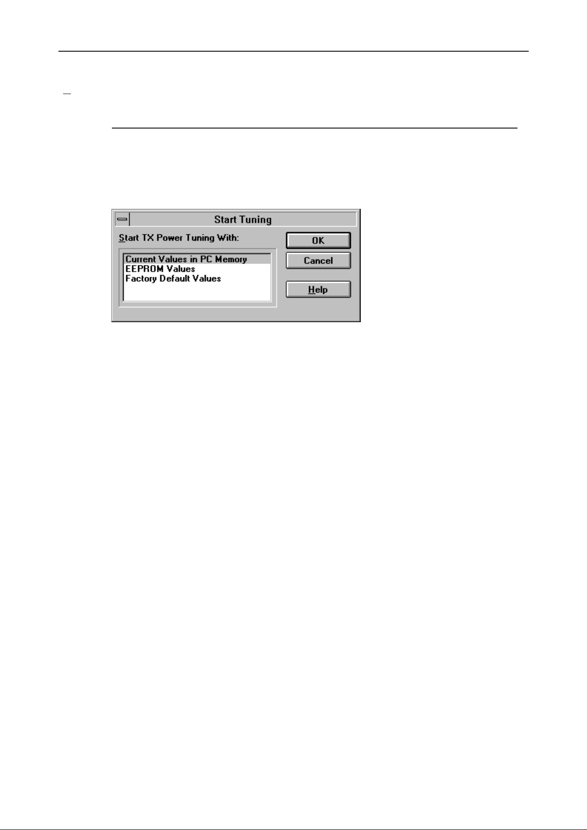
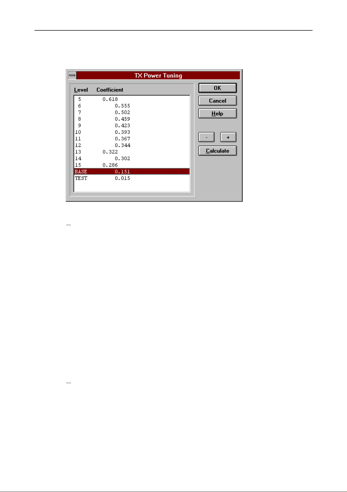
TX Power... command
Activation Status Bar Text
Alt, T, X Open TX Power Tuning dialog box
Starts TX power tuning.
The user is first requested to select with which values tuning is started in the
Start Tuning dialog box.
NHE/K–5/6 Service Software Instructions
The Start Tuning dialog box contains the following items:
Start Tuning With list box (Alt+S):
Current Values in PC memory
Tuning values are loaded from the program’s internal memory.
EEPROM Values
Tuning values are loaded from ME’s EEPROM.
Factory Default Values
Tuning values are loaded from ME’s flash.
The following are automatically selected when this tuning function is activated:
– Active Unit = TX
– the BASE power level is selected
– Operation mode = Burst
Original 05/97
Page 35
Page 36
NHE/K–5/6 Service Software Instructions
The TX Power Tuning dialog box will be activated automatically after value
selection.
After Sales
Technical Documentation
The TX Power Tuning dialog box contains the following items:
P
ower Level & Coefficients list box (Alt+P):
The power is presented in GSM values (5..15) or PCN values
(0...10). The base power is selected automatically when the dialog
box is opened. The test value is reset to 0.035 when the program is
started. The test value is not saved to the EEPROM. The test value
can be changed during tuning as other power coefficients and the
program remembers its value when tuning function is activated later
again.
If there are more power levels in the phone than can fit into the window, the window is scrollable. When the phone is initialized, the program asks the number of power levels used in the phone.
Only four power coefficients (Base, biggest, third smallest and smallest) are needed to tune and the rest of them are calculated.
The tuning position is highlighted and can be tuned with +/– keys or
left/right cursor keys.
NHE/K–6 Specific: If the application detects a phase 2 phone, the
list box will also contain phase 2 power levels.
alculate button (Alt+C):
C
Page 36
The calculation is activated with this button. The power coefficients
which are calculated from the tuned coefficients are displayed on the
different columns than the others. All values can be tuned if needed.
Original 05/97
Page 37

After Sales
Technical Documentation
+/– buttons (+/–):
The + and – buttons will cause power changing by 0.25dB steps
(D/A converter control value ratio is 1.0292). When these keys are
used, the coefficient value is updated on the tuning window.
OK button (Enter):
NHE/K–5/6 Service Software Instructions
The dialog box is closed, and tuning
Cancel button (Esc):
The dialog box is closed, and tuning
When selections are used, the power value checking is made and if it is unsuccessful, an error message is shown. The test checks that all power coefficients
are in descending order (same order as power levels).
If the power tuning function is ended and EEPROM values are not received or
EEPROM fault is noticed, an error message is shown.
When all power coefficients have such values that they don’t cause any error
messages, the dialog box will close. The last selected tuning power will be used
after exit.
Because the stored power level range is larger than the number of used power
levels, the unused levels should be set to nearest possible power level. (For example in GSM the levels 2–4 are not used, so they are set to same value as
level 5).
When this tuning function is ended, the following is automatically selected:
Active Unit = RX
is saved
is not saved
to phone.
to phone.
TX I/Q
... command
Activation Status Bar Text
Alt, T, Q Open the TX I/Q Tuning dialog box
This function is used for tuning TX I and Q branch DC offset, amplitude difference and phase difference.
The function opens the same Start Tuning dialog box as with TX Power Tun-
ing.
When this function is activated the following are automatically selected:
Active Unit = TX
Operation Mode = Burst
TX Power Level = 10(GSM); 5(PCN)
If TX Data Type = RANDOM => TX Data Type = 1
Update RF Information window
Original 05/97
Page 37
Page 38

NHE/K–5/6 Service Software Instructions
The TX I/Q Tuning dialog box is opened.
The TX I/Q Tuning dialog box contains the following items:
After Sales
Technical Documentation
Tune TX I
Tune TX Q
Tune A
Tune P
OK button (Enter):
DC Offset scroll bar (Alt+I):
The DC Offset is shown in percent (%) from the ± maximum value.
0% means that there is no DC. The value range is –100%...100%.
The value is rounded to the nearest integer value.
DC Offset scroll bar (Alt+Q):
The operation of this function is the same as one above, except with
this selection the Q branch DC Offset is tuned. The value range is
–100%...100%. The value is rounded to the nearest integer value.
mplitude Difference scroll bar (Alt+A):
When this selection is made, the user can increase or decrease the
amplitude difference in 0.1 dB steps. The value range is –1...1.
hase Difference scroll bar (Alt+P):
When this selection is made, the user can increase or decrease the
phase difference in 0.5° steps. The current phase difference is
shown in the tuning window with numbers and bar figure. The value
range is –85...95.
The dialog box is closed, and tuning
is saved
to phone.
Page 38
Cancel button (Esc):
The dialog box is closed, and tuning
After each value change, the new value is sent to the phone.
The following will be automatically selected when the TX I / Q tuning function is
ended:
Active Unit = RX
Update RF Information window
is not saved
to phone.
Original 05/97
Page 39

After Sales
Technical Documentation
Battery A/D... command
Activation Status Bar Text
Alt, T, B Calibrate battery voltage
This function is for battery a/d tuning.
Before battery a/d tuning is started, a voltage setting request is shown to the
user:
NHE/K–5/6 Service Software Instructions
When an external power is connected, and the user selects OK to continue, the
application measures a/d converter and displays the Battery A/D Calibration
dialog box.
The Battery A/D Calibration dialog box contains the following items:
R
epeat button (Alt+R):
Makes measurement again.
OK button (Enter):
The dialog box is closed, and tuning
Cancel button (Esc):
is saved
to phone.
Original 05/97
The dialog box is closed, and tuning
is not saved
to phone.
Page 39
Page 40
NHE/K–5/6 Service Software Instructions
harger A/D... command
C
Activation Status Bar Text
Alt, T, C Calibrate charger voltage
Works in the same way as the previous Battery A/D calibration.
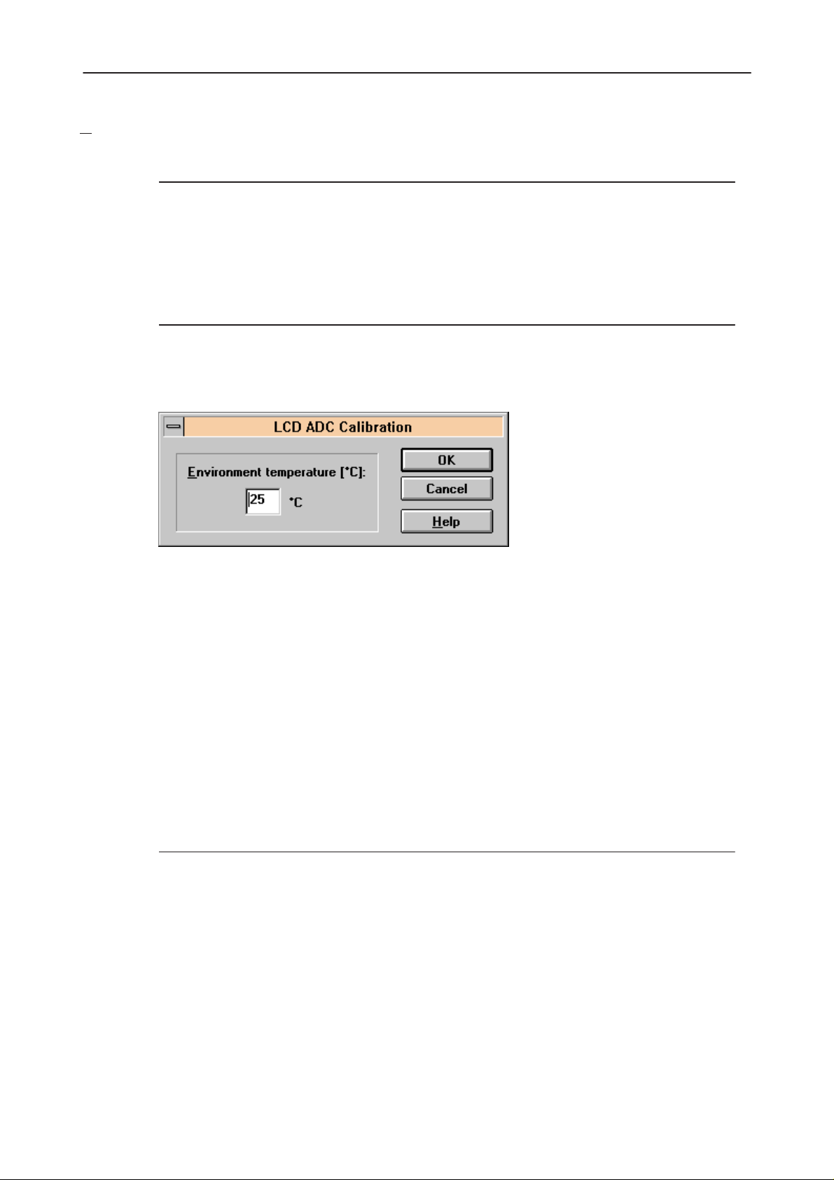
LCD A/D... command
Activation Status Bar Text
Alt, T, T, D Calibrate LCD temperature A/D
This function is for LCD ADC Calibration. Function opens the following dialog
box.
After Sales
Technical Documentation
The LCD ADC Calibration dialog box contains the following items:
Environment Temperature [°C]: edit box:
The user can change the environment temperature in the
range 0 – 80°C.
OK button (ENTER):
Closes the dialog box and saves the measured value to EEPROM.
Cancel button (ESC):
Closes the dialog box and
LCD Display... command
Activation Status Bar Text
Alt, T, T, L Tune LCD display contrast
This function is used for quick LCD display contrast tuning.
The command opens the LCD Display Tuning dialog box, which contains tools
for tuning.
does not
do any calibrations.
Page 40
Original 05/97
Page 41

After Sales
Technical Documentation
The LCD Display Tuning dialog box contains the following items:
L
CD Contrast scrollbar (ALT+L):
Enables user to tune display contrast between 1 and 31.
OK button (ENTER):
The dialog box is closed and tuning is saved to phone.
Cancel button (ESC):
NHE/K–5/6 Service Software Instructions
The dialog box is closed and tuning
is not saved
to phone.
Original 05/97
Page 41
Page 42

NHE/K–5/6 Service Software Instructions
Testing
The Testing sub menu offers functions for ME testing.
uick Testing (RF)... command
Q
Activation Status Bar Text
Alt, E, Q Open the Quick Testing dialog box
This function is used for quick RF testing.
The command opens the Quick Testing dialog box, which contains data for
testing and adjustments.
After Sales
Technical Documentation
Page 42
The Quick Testing dialog box contains the following items:
Original 05/97
Page 43

After Sales
Technical Documentation
Active Unit group:
RX radio button (Alt+R):
NHE/K–5/6 Service Software Instructions
When
The RX value is always given as default.
Note! The function is activated immediately, Apply is not needed.
TX radio button (Alt+T):
When
RX
is selected, the next functions are made:
Data transmission is deactivated
TX power is deactivated
If operation mode is continuous,
– AGC is controlled
– RX continuous mode channel is activated
RF Information window is updated
TX
is selected, the next functions are made:
Data transmission is activated
If operation mode is continuous, TX continuous mode channel is ac-
tivated
If operation mode is burst, TX power is activated
RF Information window is updated
Note! the function is activated immediately, Apply is not needed.
Operation Mode group:
C
ontinuous radio button (Alt+C):
When
Note! The function is activated immediately, Apply is not needed.
continuous
Synthesiser is set to constant frequency
Synthesiser channel number is as given with Continuous Mode
Channel selection
If Active Unit is TX, data (selected with TX Data Type) is sent
transmitter power is not connected
If Active Unit is RX, AGC is controlled
selection is used,
Original 05/97
Page 43
Page 44

NHE/K–5/6 Service Software Instructions
urst radio button (Alt+B):
B
After Sales
Technical Documentation
When
GSM/PCN receiving/transmission/measuring synthesiser. Control se-
quence synthesiser channel numbers are as given with Channel/
Monitoring Channel selections if Active Unit is TX, data (selected
with TX Data Type) is sent, and the TX power is connected
Note! The function is activated immediately, Apply is not needed.
ata Type drop list (Alt+D):
TX D
This list changes the transmission data type. The list consists of the
following options: 0, 1, and Random. After Random, data selection 0
is used. If Operating Mode is
causes different data sending than in burst mode.
T
X Power Level edit box (Alt+T):
With this value it is possible to change the transmission power. The
user can give the needed GSM/PCN power value (5..15/0...10) or
select the test value, which is tuned with TX power tuning function.
The test value is found at the end of the list.
TX Power has the value
tive unit is RX or TX power as GSM or PCN value. When the TX
power is tuned with test value (smallest value), the TX Power has
the value
burst
selection is used, the synthesiser is controlled by using
TEST
continuous
OFF
and is disabled (
.
, TX Data Type Random
greyed
) when the ac-
Ch
annel edit box (Alt+H):
The user can enter here the channel number that is used for both
transmission and receiving. The frequency of the selected channel is
shown after selection.
onitoring Channel edit box (Alt+M):
M
This field selects neighbouring monitoring channel. The frequency of
the selected channel is shown after selection.
C
ontinuous Mode Channel edit box (Alt+C):
To this edit box the user can type the continuous mode channel
which may have all GSM channel numbers (1..124) or PCN channel
numbers (512...885).
The used frequency depends on the Active Unit. If the Active Unit is
RX, then RX frequency is used, else TX frequency. The frequency of
the selected channel is shown after selection.
Page 44
Original 05/97
Page 45

After Sales
Technical Documentation
AGC edit box (Alt+G):
This selection allows user to edit the AGC absolute value (value from
A/D converter). The AGC can have values from 0dB to 93dB in 3dB
steps in GSM, and from 0dB to 81dB in PCN.
The AGC value is shown only when its value is controlled by the PC. When the
Active Unit has value RX and Operation Mode is continuous, AGC is controlled
by the PC except when next adjustment functions are activated:
RSSI Calibration
AFC Diagram
AF
C edit box (Alt+F):
This selection allows the user to edit the AFC D/A converter value.
The AFC can have values from –1024 to 1023.
The AFC value is the last measured AFC D/A converter value (11 bit 2–comple-
ment value is used with decimal digits). If the AFC results are not received, no
text is shown. The AFC value is neither shown in the next situations i.e. when
AFC is not controlled by PC:
NHE/K–5/6 Service Software Instructions
AFC Diagram
pply button (Alt+A):
A
Accepts entered values and validates them. After validation, the ap-
plication sends corresponding messages to ME. Closes the dialog
box, and updates Info Window.
Note: Active Unit and Operation mode command do not use the Apply button,
as they are activated immediately.
Set Defaults button (ALT+S):
Sets current values as default Quick Test values.
Ge
t Defaults button (ALT+E):
Gets default Quick Test values as current values.
NHE/K–6 Specific:
Antenna P
ath drop list (ALT+P)
Enables switching for antenna path between normal antenna and
system cable.
The following are automatically done when the Quick testing function is ended:
Original 05/97
Active Unit = RX
Update RF Information window
Page 45
Page 46

NHE/K–5/6 Service Software Instructions
The next table shows the dialog box’s properties in different situations:
ACTIVE UNIT = TX:
TX Data Type: Updated
AGC values: Greyed
Monitoring Channel: Greyed
OPERATION MODE = BURST:
TX Power Level: Updated
Continuous Mode Channel: Greyed
Channel: Updated
OPERATION MODE = CONT.:
TX Power Level: OFF, Greyed
After Sales
Technical Documentation
ACTIVE UNIT = RX:
TX Data Type: Greyed
TX Power Level: OFF, Greyed
OPERATION MODE = BURST:
OPERATION MODE = CONT:
Continuous Mode Channel: Updated
Channel: Greyed
AGC values: Greyed
Continuous Mode Channel: Greyed
Channel: Updated
Monitoring Channel: Updated
AGC values: Updated
Continuous Mode Channel: Updated
Channel: Greyed
Monitoring Channel: Greyed
Page 46
Original 05/97
Page 47

After Sales
Technical Documentation
RSSI Reading... command
Activation Status Bar Text
Alt, E, R Open RSSI Reading dialog box
The command is used for reading RSSI values.
When the selection is made, the test result will be shown to the user in the
RSSI Reading dialog box:
NHE/K–5/6 Service Software Instructions
Original 05/97
Page 47
Page 48

NHE/K–5/6 Service Software Instructions
elf Tests... command
S
Activation Status Bar Text
Alt, E, S Open MCU Self–tests dialog box
The command is used for reading self test results and running self tests.
When the selection is made, the test result is read from ME. The test result will
be shown to the user within the MCU Self–test dialog box.
After Sales
Technical Documentation
Page 48
The MCU Self–test dialog box contains the following items:
T
ests list box (Alt+T):
The field ”(p)” in the screen example means that the test is also run
in power up.
The field “/s)” means that this test is selectable one.
Test states are updated according to results received from the
phone. Possible test states will be one of the following:
Passed
Failed
No response
Not executed
RUNNING....
Original 05/97
Page 49

After Sales
Technical Documentation
Run button (Alt+R):
The user can select desired test from list and hit Run button. When
user selects test to be run, the text
state field, and test is run. When results are received, the test state
field is updated according to the result.
NHE/K–5/6 Service Software Instructions
RUNNING...
is shown in the test
Run A
Supported Self Tests
1 MCU RAM Interface Test..........:
2 MCU RAM Component Test..........:
3 MCU EEPROM Interface Test.......:
4 MCU EEPROM Component Test.......:
5 MCU ROM Partial Checksum Test...:
6 MCU ROM Checksum Test...........:
7 MCU Audio Codec Interface Test..:
8 ASIC NMI Test...................:
ll button (Alt+A):
If no response was received in the defined time, a
box
will be shown and the test state is changed to
The user can run all listed tests. The text
the test state field, and test is run. When results are received, the
test state field is updated according to the result. When the state
field is updated, the application moves to the next test and repeats
previous cycle.
RUNNING...
error message
No response
is shown in
.
9 ASIC Reset Reg Interface Test...:
A ASIC Timer and IRQ0 Test........:
B ASIC and IRQ1 Test..............:
C ASIC Correct Test...............:
D SW Reset Test...................:
E DSP Code Download Test..........:
F DSP Alive Test..................:
G Tuning Value Checksum...........:
H SIM Lock Check..................:
I IMEI Check......................:
Original 05/97
Page 49
Page 50

NHE/K–5/6 Service Software Instructions
DC Readings... command
A
Activation Status Bar Text
Alt, E, A Open the ADC Readings dialog box
The command is used to read and show A/D values from phone.
The command opens the ADC Readings dialog box:
After Sales
Technical Documentation
The ADC Readings dialog box has static text fields where measurements are
updated to the window every one second.
A/D Readings
The following a/d readings are measured:
Battery Voltage :. . . . . . . . . . . . .
Charge Voltage :. . . . . . . . . . . . .
Battery Temperature :. . . . . . . .
Battery Size :. . . . . . . . . . . . . . . .
A/D Reference. . . . . . . . . . . . . . :
Accessory Detection. . . . . . . . . .:
LCD Temperature . . . . . . . . . . :
Hook Info . . . . . . . . . . . . . . . . . . :
Page 50
Original 05/97
Page 51

After Sales
Technical Documentation
Audio... command
Activation Status Bar Text
Alt, E, U Open Audio Tests dialog box
The command is used for making audio tests in the Audio Tests dialog box.
NHE/K–5/6 Service Software Instructions
The Audio Tests dialog box contains following items:
Buzzer group:
The next two different values can be selected for Buzzer volume:
V
olume On radio button (ALT+V):
Turns buzzer on.
Volume O
Internal Audio Loop group:
Input group:
The next two different values can be selected for input:
I
nternal radio button (Alt+I):
E
xternal radio button (Alt+I):
ff radio button (ALT+O):
Turns buzzer off.
Switches to internal input.
Switches to external input.
Original 05/97
Page 51
Page 52

NHE/K–5/6 Service Software Instructions
Output group:
The next two different values can be selected for output:
ernal radio button (Alt+T):
Int
Switches to internal output.
Ex
ternal radio button (Alt+X):
Switches to external output.
Loop group:
The next two different values can be selected for loop:
Off
radio button (Alt+F):
Turns audio loop off.
On
radio button (Alt+N):
Turns audio loop on.
When the dialog box is closed, the Buzzer Volume is always switched off. The
internal audio loop is also turned off.
After Sales
Technical Documentation
D
isplay... command
Activation Status Bar Text
Alt, E, D Open Display Tests dialog box
This command is used for making display tests in the Display Tests dialog box.
The Display Tests dialog box contains the following items:
1
. Test Pattern radio button (Alt+1):
2
. Test Pattern radio button (Alt+2):
In test display 1 half of the indicators are displayed, and the display
is filled with chessboard letters.
In test display 2 the remainder (from test 1) of the indicators are displayed, and the display is filled with inverse chessboard letters.
Page 52
When the dialog box is closed, the phone LCD display is cleared.
Original 05/97
Page 53

After Sales
Technical Documentation
Call Simulation.. command
Activation Status Bar Text
Alt, E, C Open Call Simulation dialog box
The command is used for making call simulation. The function opens the Call
Simulation dialog box.
NHE/K–5/6 Service Software Instructions
The Call Simulation dialog box contains the following items:
T
X Power Level edit box (Alt+T):
All power levels can be selected. This updates same parameter as
TX Power Level in the RF–Controls dialog box. Note that TEST
value cannot be selected. If TEST value was in use when Call simulation menu selected, power level is changed to smallest value.
hannel edit box (Alt+C):
C
This tells the normal operating RF channel number. Normal GSM/
PCN channel numbers can be selected. Same channel is used both
for transmission and receiving. This updates same parameter as
Channel in the RF–Controls dialog box.
Monitoring Channels group:
Channel 1,2,3,4,5,6 edit box (Alt+1,2,...):
Channels for monitoring are specified with these six selections. All
GSM/PCN channel numbers can be used. If more than one selection
has same number, the monitoring channel list (neighbour list) will
have less than 6 selected channels. The minimum number of moni-
toring channels is one (all channels have same value). The monitor-
ing channel can also have same value as normal operating channel.
Original 05/97
The first monitoring channel updates the same parameters as Moni-
toring Channel in the RF–Controls dialog box.
Page 53
Page 54

NHE/K–5/6 Service Software Instructions
pply button (Alt+A):
A
Validates and sends entered data to ME.
S
et Defaults button (ALT+S):
Sets current values as default Call Simulation values.
Ge
t Defaults button (ALT+E):
Gets default Call Simulation values as current values.
Noise Sensitivity... command
Activation Status Bar Text
Alt, E, N Opens Noise Sensitivity dialog box
The command is used for noise sensitivity measurement.
The following are automatically selected when this tuning function is activated:
After Sales
Technical Documentation
– Active Unit = RX
– Operation mode = Continuous
– AGC = 81 dB
Function opens next a Noise Sensitivity dialog box.
The application then opens the Noise Sensitivity dialog box:
Page 54
Original 05/97
Page 55

After Sales
Technical Documentation
The Noise Sensitivity dialog box contains the following items:
Measurements group:
Clipping distance is the difference to the signal clipping value. SNR
is measured in the AD converter.
Clipping distance = clipping level (66) – signal value + comp_factor1
SNR = signal value – noise value + comp_factor1
Sensitivity = –92 dBm + 8 dB + comp_factor2 – SNR (for GSM)
Sensitivity = –90 dBm + 8 dB + comp_factor2 – SNR (for PCN)
The last value on the display is signal power difference between I
and Q branch. The numbers are shown in 0.1dB accuracy. The error
messages, ”OUT OF RANGE”, are shown only if the SNR and/or
amplitude difference values are not acceptable (SNR <= 18 dB +
comp_factor2 – 0.5 dB(= accuracy) ; Sensitivity >= –100 dBm + 0.5
dB ; |Si – Sq| > 1 dB).
ignal/Noise button (Alt+S/Alt+N):
S
NHE/K–5/6 Service Software Instructions
When the buttons are pressed, the RX I and Q burst data is asked,
text ”SIGNAL MEASURING...” or ”NOISE MEASURING...” will apear
in the measurement group window. The power level value should be
–92 dBm during signal measurement.
When signal data is received, distance to clipping signal level is
shown as dBs on the display. When either signal or noise measure-
ment results are received ”MEASURING” text is removed and mea-
surements are updated to screen. When both measurements (signal
and noise) are done at least once, the signal to noise relation and
difference are also shown on the display.
After exiting the dialog box, the following are set to the values which were selected before this adjustment.
– Active Unit
– Operation mode
– AGC value
Compensation factors:
comp_factor1 = 4.64 dB (Compensation factor for 67.71 kHz signal, because
ASIC filter attenuates 67.71 kHz signal 4.64 dB)
comp_factor2 = 2.27 dB (Compensation factor for real and calculated noise
bandwidth difference. Real noise bandwidth is 80 kHz and calculated bandwidth is 135 kHz)
Original 05/97
Page 55
Page 56

NHE/K–5/6 Service Software Instructions
Software
The settings sub menu offers functions for Mobile Equipment mode and
memory settings.
After Sales
Technical Documentation
Phone I
dentity... command
Activation Status Bar Text
Alt, S, I Opens the Phone Identity dialog box for editing
The function is used to edit phone identity. The function opens the Phone Iden-
tity dialog box:
The Phone Identity dialog box contains the following items:
I
MEI edit box (Alt+I):
Field where the user can enter current IMEI value. Field can contain
up to 40 digits.
HW V
OK button (Enter):
Cancel button (Esc):
ersion edit box (Alt+V):
Field where user can enter current HW version. Field can contain
four digits and one dot. Dot is not sent to ME.
Checks if some values are changed and if IMEI was modified, asks
for confirmation. After confirmation, it writes values to phone.
Cancels all edits and does not save values to phone.
Page 56
Original 05/97
Page 57

After Sales
Technical Documentation
Product Profile... command
Activation Status Bar Text
Alt, S, P Open Product Profile Settings dialog box
The function is used for making product profile settings.
When the command is activated, the product profile information is read from
the EEPROM and the Product Profile dialog box is opened.
NHE/K–5/6 Service Software Instructions
The Product Profile dialog box contains the following items:
Se
ttings list box (Alt+E):
A list where the user can select desired setting.
The user can toggle settings with following Options drop list, or by
double clicking the desired setting in list box.
O
ptions drop list (Alt+O):
List allows user to set options to each setting listed in the Settings
list box. Possible options per setting are:
OK button (ENTER)
Selections are accepted and saved to EEPROM.
Cancel button (ESC)
Selections are ignored and control is returned back to main menu.
Original 05/97
Page 57
Page 58

NHE/K–5/6 Service Software Instructions
ave File... button
S
Allows the user to save settings to file. Opens a standard windows
File Save dialog box.
oad File... button
L
Allows the user to load the settings from a file. Opens a standard
windows File Open dialog box.
NHE/K–5 Product Profile Settings
The following settings are available:
Russian Language On/Off
Italian Language On/Off
Greek Language On/Off
Turkish Language On/Off
Keypad Type Nokia Design 1/2/OEM
After Sales
Technical Documentation
Redial Type GSM, Non GSM
CO SMS Appearance Normal/Enhanced
Service Numbers Available/Not Available
Forced SIM Clock stop On/Off
See the NHE–5/NHK–5 Product Profile Specification for more info.
Note! When forced SIM Clock Stop is switched ON, stand–by time is increased
consideraby
NHE/K–6 Product Profile Settings
The following settings are available:
Redial Type GSM, Non GSM
Italian Language On/Off
Greek Language On/Off
Turkish Language On/Off
Russian Language On/Off
Hungarian Language On/Off
Page 58
Ringing Tone Set Default Set/Set 1
Forced SIM Clock stop On/Off
See the NHE–6/NHK–6 Product Profile Specification for more info.
Note! When forced SIM Clock Stop is switched ON, stand–by time is increased
consideraby
Original 05/97
Page 59

After Sales
Technical Documentation
Start Up Self–tests... command
Activation Status Bar Text
Alt, S, S Open MCU Start Up Self–tests dialog box
The function is used for changing the state of the EEPROM selectable tests in
the MCU Start Up Self–tests dialog box.
NHE/K–5/6 Service Software Instructions
The MCU Start Up Self–tests dialog box contains the following items:
T
ests list box (Alt+T):
When dialog box is opened, the previous values will be read from the
MCU EEPROM and shown on the list box.
Status group:
When radio button On is selected, the test will be run every time
when automatic start up self–tests are activated (e.g. in power up).
OK button (Enter)
Selections are accepted and saved to EEPROM. A power up routine
is made to phone.
Cancel button (Esc)
Selections are ignored and control is returned back to main menu.
Original 05/97
Page 59
Page 60

NHE/K–5/6 Service Software Instructions
After Sales
Technical Documentation
Set Default V
Activation Status Bar Text
Alt, S, V Set factory default values
The command is used for resetting default values to phone’s EEPROM.
After selection, the following Default Settings dialog box is opened:
The Default Settings dialog box contains the following items:
S
elect Settings list box (Alt+S):
alues... command
Enables user to select set to be reset: UI/DEV Factory Set, Factory
Set or Full Factory Set.
OK button (Enter)
Closes the dialog box and writes the selected set to the EEPROM of
the phone.
Cancel button (Esc)
Closes the dialog box and
does not
write settings to the phone.
Page 60
Original 05/97
Page 61

After Sales
Technical Documentation
Network Settings... command
Activation Status Bar Text
Alt, S, N Open Network Settings dialog box
After selection the following Network Settings dialog is opened:
NHE/K–5/6 Service Software Instructions
The Network Settings dialog contains the following items:
NSPS Settings group:
M
in Time edit box (ALT+M):
Max
C
ontrol drop list (ALT+C):
Original 05/97
Minimum time for NSPS.
Time edit box (ALT+X):
Maximum time for NSPS.
NSPS Control values:
– Stop by send key
– Stop by any key
– No key control
– NSPS not supported
Page 61
Page 62

NHE/K–5/6 Service Software Instructions
Custom Operator Name group:
untry Code:
Co
Specified country code
Netw
ork Code:
Specified network code
N
ame:
Name of the operator matching with country and network code.
Length for operator name is 8 characters for NHE/K–5, and 10 char-
acters for NHE/K–6.
arranty State... command
W
Activation Status Bar Text
Alt, S, W Opens the Warranty State dialog box.
After Sales
Technical Documentation
This command is used for setting the Phone’s Warranty State. The function
opens the following Warranty State dialog box.
The Warranty State dialog box contains the following items:
State: static text:
USE
For normal phones.
Page 62
DEFECTIVE
For phones which are being swapped. Warranty and other information is transferred to the working phone.
EXCHANGE
For phones which are already repaired from DEFECTIVE ones.
Original 05/97
Page 63

After Sales
Technical Documentation
Repair Date edit box (Alt+R):
Format is MMYY (Where MM is month and YY two last digits of the
year). The date is read from PC’s clock. This is enabled only if state
is DEFECTIVE.
OK button (ENTER):
Closes the dialog box, and saves the Warranty State to the phone.
This button should be enabled only when phone is DEFECTIVE and
repair date is entered.
Cancel button (ESC):
Closes the dialog box, and does not save the Warranty State to the
phone.
NHE/K–5/6 Service Software Instructions
Service Numb
Activation Status Bar Text
Alt, S, B Opens the Service Numbers dialog box.
This command is used for setting the phone’s Service Numbers. This feature is
available only in few countries. The function opens the following Service Num-
bers dialog box.
The Service Numbers dialog box contains the following items:
ers... command
Number 1,2,3
OK button (ENTER):
Cancel button (ESC):
Original 05/97
edit fields:
Contains Service Numbers which can be called by pressing 1,2 and
3 numbers in keypad for prolonged time period. Service numbers are
3 digits long.
Closes the dialog box, and saves the numbers to the phone.
Closes the dialog box, and
does not
save the numbers to the phone.
Page 63
Page 64

NHE/K–5/6 Service Software Instructions
lash Phone... command
F
Activation Status Bar Text
Alt, S, F Opens the Flash Phone dialog box.
This command is used to flash the phone. The function opens the following
Flash Phone dialog box.
After Sales
Technical Documentation
The Flash Phone dialog box contains the following items:
Close button (ESC):
Closes the dialog box, and
Fl
ash button (Alt+L):
Transfers the specified file to the phone.
S
elect File button :
Allows selection of the flash file.
does not
flash the phone.
Page 64
Original 05/97
Page 65
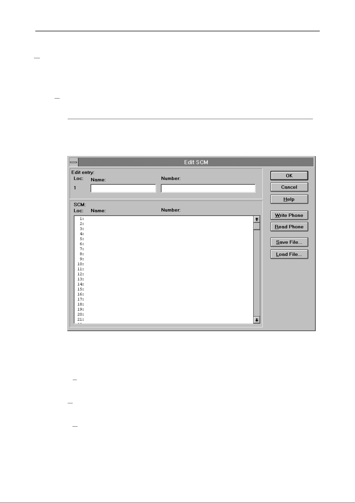
After Sales
Technical Documentation
Dealer
The dealer sub menu offers functions for Mobile Equipment settings for dealers.
NHE/K–5/6 Service Software Instructions
Short C
ode Memory... command
Activation Status Bar Text
Alt, D, C Opens the Edit SCM dialog box.
This command is used for reading, storing and modifying the SCM values. The
function opens the following Edit SCM dialog box:
The Edit SCM dialog box contains the following items:
Loc static text:
Na
N
umber edit box (ALT+N):
SC
Original 05/97
Displays current location.
me edit box (ALT+A):
Edit the Name.
Edit the number.
M list box (ALT+C):
List for available names and numbers.
Page 65
Page 66

NHE/K–5/6 Service Software Instructions
rite Phone... button (ALT+W):
W
Write SCM values to phone and checks the validity of names and
numbers.
ead Phone... button (ALT+R):
R
Read SCM values from phone.
S
ave File... button (ALT+S):
Opens a default Windows File Save As dialog box, and asks for a
filename where to save SCM values.
L
oad File... button (ALT+L):
Opens a default Windows File Open dialog and asks for a filename
where from to load SCM values. Checks the validity of names and
numbers.
User Settings... command
After Sales
Technical Documentation
Activation Status Bar Text
Alt, D, U Open User Settings and Values dialog box
This command is used to read, store, and modify the user settings and values.
After menu selection, the program responds with a
user settings from phone?”. If user answers Yes, all needed user settings will
be read from the ME, including menu settings. If a reading error happens, an
error
dialog box is shown. If reading is successful, the User Settings and Val-
ues dialog box is opened:
For NHE/K–5:
query
dialog box: “Read
Page 66
Original 05/97
Page 67

After Sales
Technical Documentation
For NHE/K–6:
NHE/K–5/6 Service Software Instructions
The User Settings and Values dialog box contains the following items:
Se
curity ID edit box (Alt+E):
Edit the security code which is saved to the ME memory together
with other user settings and values. Only digits are accepted for Se-
curity code. Length must be 5 digits.
Master Code static:
Code is 10 digits length and it is read only.
Wake up M
ave File... button (Alt+S):
S
L
oad File... button (Alt+L):
essage edit box (Alt+M):
Edit Wake up message. The wake up message name can have up to
16 characters.
Opens a default Windows File Save As dialog box and asks file-
name where to save user settings and values.
Opens a default Windows File Open dialog box and asks filename
where from load user settings and values.
Original 05/97
Page 67
Page 68

NHE/K–5/6 Service Software Instructions
For NHE/K–6:
Preview image:
This image area shows the current wake up message graphics bit-
map.
dit button (ALT+E):
E
The user can launch the MS Windows Paint Brush application with
current bmp file and edit it.
Data entered in the dialog box is checked for validity before it is sent to the
phone. If the application finds wrong characters from the Wake up message,
the application will inform the user, and request correction. The information window is shown during writing. The window tells how much time it will approximately take to write values.
When all values are sent and responses received, waiting window is removed
and User Settings and Values is back in control. The waiting state can be bro-
ken with Cancel (Esc) button. If writing to the ME is broken, only part of the values in the ME may be changed.
After Sales
Technical Documentation
Both save file and load file function has default name which is previously used
name. For instance if user data was saved to file USERA.USR and read function is activated the default value is USERA.USR.
& User Settings... command
SCM
Activation Status Bar Text
Alt, D, M Open SCM & User Setttings dialog box.
This command is used to get SCM and user settings from phone to file and vice
versa. When settings are read from the phone, all user settings are read from
the phone and saved to file, in NHE/K–6 phones the graphical wake up message and SCM are also saved. When settings are written to the phone, all user
settings except master code are loaded from file, in NHE/K–6 phones graphical
wake up message and SCM are also loaded.
When data is written to or read from the phone, a waiting dialog box is shown.
Page 68
Original 05/97
Page 69
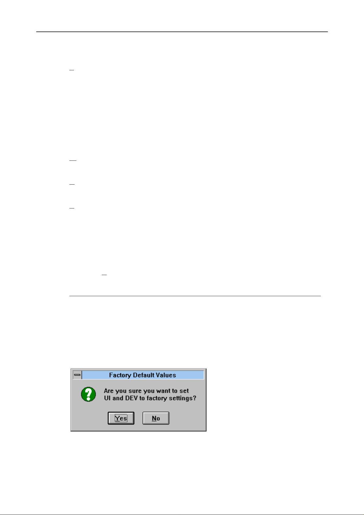
After Sales
Technical Documentation
The SCM & User Setttings dialog box contains the following items:
F
ile Name edit box (ALT+F):
The user can edit the file name or select another file with the Open
File dialog box. When the dialog box is opened, it contains the name
of the previously saved or loaded file. Note that for NHE/K–6 phones
the graphical wake up message is saved in its own file. If for exam-
ple other settings iare saved to the file c:\tmp\default.suc, then the
grapical wake up message is saved to file c:\tmp\default.bmp.
Close... button (ESC):
Closes the dialog box.
rite Phone... button (ALT+W):
W
Loads settings from file and writes them to phone.
R
ead Phone... button (ALT+R):
Reads settings from phone and writes them to file.
NHE/K–5/6 Service Software Instructions
S
elect File... button (ALT+S):
Set UI/DEV Default V
Activation Status Bar Text
Alt, D, V Reset phone to UI and DEV factory settings
After selection, the application asks for confirmation: “Are you sure you want to
reset UI and DEV to factory settings?”. If Yes is answered, default settings are
reset to the phone.
Opens the Open File dialog box, with which the user can select the
file that contains the data to be loaded to ME, or the file to which
data is saved from ME. If the user selects OK button, the name of
the selected file is copied to the File Name edit field.
alues... command
Original 05/97
Page 69
Page 70

NHE/K–5/6 Service Software Instructions
View
Quick/RF Info... command
Activation Status Bar Text
Alt, V, Q View Quick/RF information
After Sales
Technical Documentation
If phone is in
Note! Special conditions (For example, if the phone’s SIM lock is ON) cause
this dialog box to change color to make this special condition clear to the user.
If the phone is in local mode, the following RF Information is shown. Information is shown in a modeless dialog box which may be left open during other operations. It is also updated when ever needed.
normal
mode, the following Quick Info is shown:
Page 70
Original 05/97
Page 71

After Sales
Technical Documentation
Phone Identity... command
Activation Status Bar Text
Alt, V, P View phone identity
The command opens the Phone Identity Information dialog box, which shows
identification information. Information is shown in a modeless dialog box, which
may be left open during other operations. It is also updated when ever needed.
NHE/K–5/6 Service Software Instructions
Original 05/97
Page 71
Page 72

NHE/K–5/6 Service Software Instructions
Help
The Help menu offers commands which provide assistance with this application:.
ndex command
I
Activation Status Bar Text
Alt, H, I Provide general instructions on using help
The command displays the opening screen of Help. From the opening screen,
the user can jump to step–by–step instructions for using Service Software and
various types of reference information.
Once Help is opened, the user can click the Contents button whenever he
wants to return to the opening screen.
eneral help command
G
After Sales
Technical Documentation
Activation Status Bar Text
Alt, H, G General help
sing Help command
U
Item Activation Status Bar Text
Using Help Alt, H, U Display using help system
bout... command
A
Activation Status Bar Text
Alt, H, A Displays the version number of this application
See Login Dialog.
information
SHIFT F1
Page 72
Original 05/97
Page 73

After Sales
Technical Documentation
Initialization File
The service software has its own initialization file which has the extension .INI.
The Initialization file is TESLA.INI and includes all the following selections (in
mentioned menus or dialog boxes) and parameters:
RF Controls dialog box ([NHE/K–5 RF ])
Channel (Channel =)
Continuous Mode Channel (Cont Mode Channel =)
Monitoring Channel (Monitoring Channel =)
AFC (AFC =)
AGC (AGC =)
Data Type (DataType=)
Power Level (PowerLevel =)
DLL Filenames (NHE–5 and identical NHE–6)
NHE/K–5/6 Service Software Instructions
User Interface (UserInterface=)
Functionality (Functionality=)
RSSI Dialog box (NHE–5LEVELS and identical NHE–6LEVELS)
AFC Level (AfcLevel=)
RSSI Low (RssiLow=)
RSSI High (RssiHigh=)
AFC Level (AfcLevel=)
Original 05/97
Page 73
Page 74

NHE/K–5/6 Service Software Instructions
Appendix 1, Vocabulary
Appreviation Description
API Application Programming Interface
ASIC Custom circuit which for instance controls communication
between MCU and DSP
CLF Common Look and Field
DATA DATA interface module
DAU–4S M2BUS – RS–232 adapter
DCT2 Digital Core Technology Second Generation
DLL Dynamic Link Library
DSP Digital signal processor which controls radio interface and
speech coding/decoding
After Sales
Technical Documentation
EEPROM Memory for adjustment parameters (Electrically Erasable
and Programmable Read Only Memory)
IMEI International Mobile Equipment Identification code
M2BUS Serial communication bus which can be connected to
accessory devices and test PC
MCU Master Control Unit processor
MDI MCU DSP Interface; message interface via ASIC registers
ME Mobile Equipment
MFC Microsoft Foundation Class library
MS Mobile Station
MTI Message Transfer Interface
PC IBM PS/AT or compatible personal computer
PCBOX Local Net driver SW for PC
PCI Phone Controlling Interface SW for PC
PKD Parallel Port Software Protection Device
RF Radio Frequency parts
Page 74
RFI Radio Frequency Interface circuit
SW Software
UI User Interface
Original 05/97
 Loading...