

Page 1

Nokia Customer Care
RH-47 Series Cellular Phones
5 - Disassembly & Assembly
Instructions
Issue 1 05/04 Copyright © 2004 Nokia Corporation Page 1
Company Confidential
Page 2

RH-47 Company Confidential
5 - Disassembly Instructions Nokia Customer Care
[This page intentionally blank]
Page 2 Copyright© 2004 Nokia Corporation Issue 1 05/04
Company Confidential
Page 3

Company Confidential RH-47
Nokia Customer Care 5 - Disassembly Instructions
Table of Contents
Page No
Disassembly............................................................................................................................................... 4
Required tools .......................................................................................................................................5
Disassembly instructions ....................................................................................................................5
Assembly ................................................................................................................................................. 13
Required tools .....................................................................................................................................13
Assembly instructions .......................................................................................................................14
Issue 1 05/04 Copyright © 2004 Nokia Corporation Page 3
Company Confidential
Page 4

RH-47 Company Confidential
5 - Disassembly Instructions Nokia Customer Care
[This page intentionally blank]
Page 4 Copyright© 2004 Nokia Corporation Issue 1 05/04
Company Confidential
Page 5
Company Confidential RH-47
Nokia Customer Care 5 - Disassembly Instructions
Disassembly
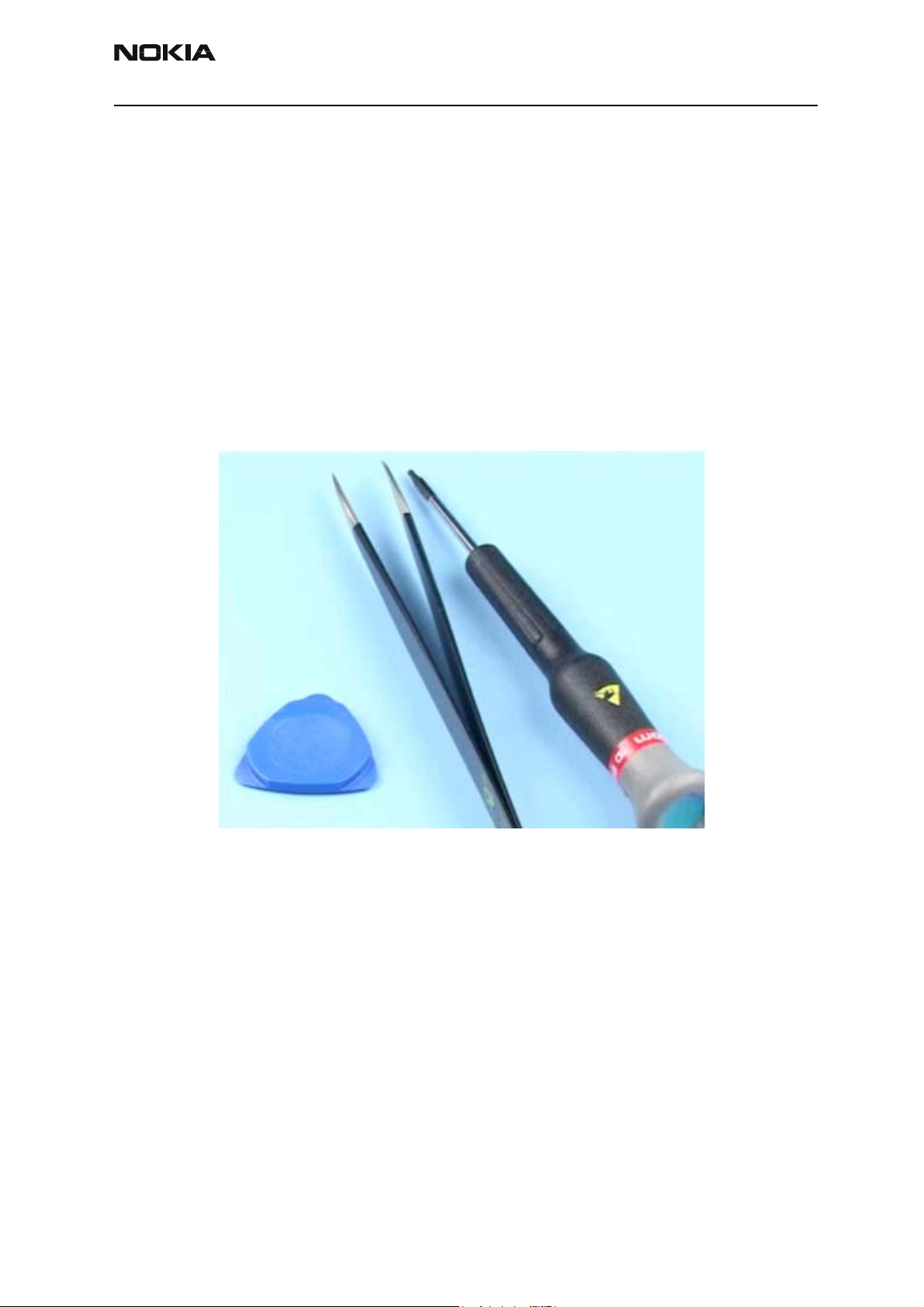
Required tools
• SRT-6 opening tool
• Tweezer (ESD compliant)
• Torx T6 screwdriver (ESD compliant)
•Gloves
• SS-33 A-cover opening tool (recommended)
Figure 1: Required tools for disassembly
Issue 1 05/04 Copyright © 2004 Nokia Corporation Page 5
Company Confidential
Page 6
RH-47 Company Confidential
5 - Disassembly Instructions Nokia Customer Care
Disassembly instructions
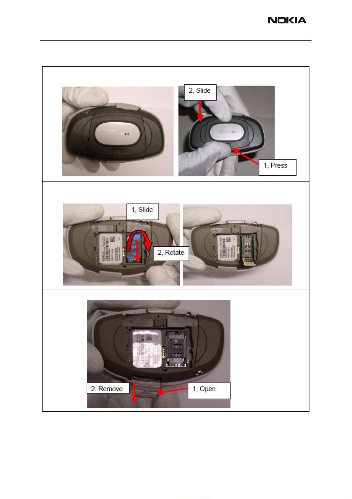
1. To remove the battery cover, press the battery cover release button (1) and remove the cover by sliding it
towards the connectors (2). Remove the battery (there is no locking).
2. To remove the SIM card, slide (1) the SIM card holder downwards. Then rotate the holder (2) to open the SIMconnector latch and remove the SIM card.
3. To remove the MMC card, open (1) the MMC lid in grip and remove (2) the card.
Page 6 Copyright © 2004 Nokia Corporation Issue 1 05/04
Company Confidential
Page 7
Company Confidential RH-47
Nokia Customer Care 5 - Disassembly Instructions
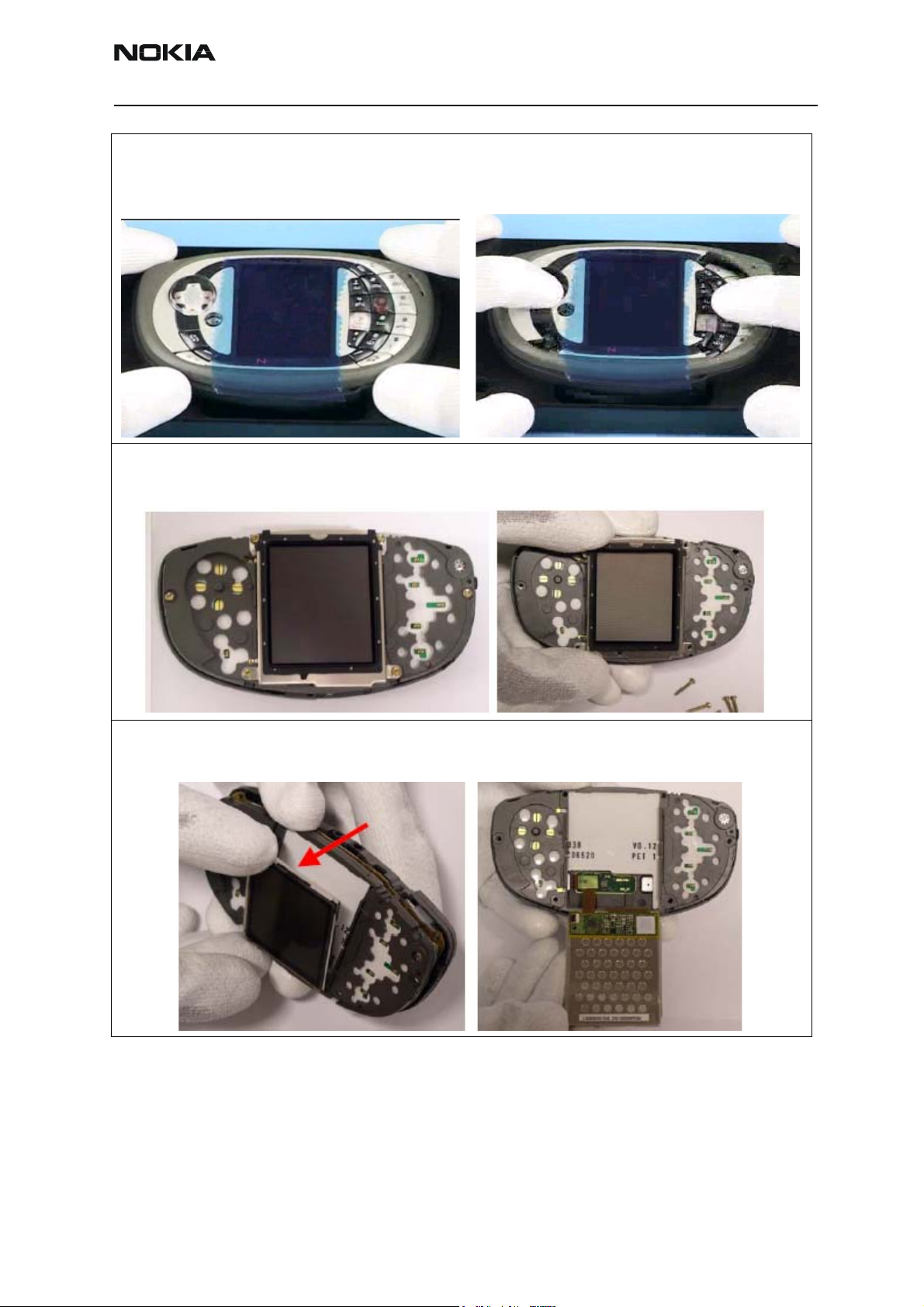
4. Place the device onto an SS-33 opening tool. To remove the A-cover, grip and keymat, push the keymat from
the rocker and T9 area with the thumbs. Keep pushing and at the same time help with index fingers from the left
and right outer edges of the device.
Remove the A-cover and grip. Remove keymats (there is no locking).
5. To remove the LCD shield, remove screws (6 pcs) by using Torx T6 screwdriver. Remove the LCD shield carefully.
Note for reassembly. When reassembling use 27 Ncm torque for the screws. The order for tightening the screws
in reassembly is showed in the reassembly section.
6. To remove the LCD module, carefully lift (it is not locked to keyguide) it from the upper edge. Tilt the LCD module 180 degrees. Support the LCD module to avoid damaging the module, connectors or flex because LCD connector is still connected.
Issue 1 05/04 Copyright © 2004 Nokia Corporation Page 7
Company Confidential
Page 8

RH-47 Company Confidential
5 - Disassembly Instructions Nokia Customer Care
7. Use a special opening tool SRT-6 to unplug the LCD connector.
8. To remove the keyguide assembly, simply lift it (it is not locked).
Page 8 Copyright © 2004 Nokia Corporation Issue 1 05/04
Company Confidential
Page 9

Company Confidential RH-47
Nokia Customer Care 5 - Disassembly Instructions
9. Unclip the snaps (2 pcs) on top of the keyguide with a fingernail or a tool and remove parts. Be careful not to
break the snap feature in keyguide.
10. To remove the earpiece from keyguide push the component on top side of the keyguide.
11. To remove UI PWB from the center frame assembly, pull them apart.
Issue 1 05/04 Copyright © 2004 Nokia Corporation Page 9
Company Confidential
Page 10

RH-47 Company Confidential
5 - Disassembly Instructions Nokia Customer Care
12. To remove the engine PWB, simply lift it out from the B-cover.
13.Use tweezers or fingers to remove the antenna assembly.
14.Use tweezers to remove the power switch actuator.
15. Use fingers or tweezers to remove the DC-jack.
Page 10 Copyright © 2004 Nokia Corporation Issue 1 05/04
Company Confidential
Page 11

Company Confidential RH-47
Nokia Customer Care 5 - Disassembly Instructions
16. Use fingers or tweezers to remove the line-ins.
17. Use tweezers to remove the vibra.
18. Use fingers to remove the IHF-lid.
Issue 1 05/04 Copyright © 2004 Nokia Corporation Page 11
Company Confidential
Page 12

RH-47 Company Confidential
5 - Disassembly Instructions Nokia Customer Care
19. To remove the HF/Malt speaker, use SRT-6 to carefully lift it up. Use tweezers to remove it.
Be careful because there are thin wires on the speaker that can be easily damaged.
Note for Reassembly. The HF/Malt speaker is fixed with a double-sided adhesive. Use a new adhesive when reassembling.
Page 12 Copyright © 2004 Nokia Corporation Issue 1 05/04
Company Confidential
Page 13

Company Confidential RH-47
Nokia Customer Care 5 - Disassembly Instructions
Assembly
Required tools
• SRT-6 opening tool
• Tweezer (ESD compliant)
• Dynamometric Torx T6 screwdriver (ESD compliant), 28-30 Ncm
• Torx T6 screwdriver
•Gloves
Figure 2: Required tools for assembly
Issue 1 05/04 Copyright © 2004 Nokia Corporation Page 13
Company Confidential
Page 14

RH-47 Company Confidential
5 - Disassembly Instructions Nokia Customer Care
Assembly instructions
1. Use tweezers to reassemble the Malt Speaker. Use the 2 holes on top of the speaker to avoid damaging the
speaker. There are thin wires that can be easily damaged.
The Malt speaker is fixed with a double-sided adhesive. Use a new adhesive when reassembling. Note the correct
assembly position. There is a nose in the speaker and a recess in the B-cover. The nose should go into the recess.
2. Use tweezers or fingers to reassemble the IHF-lid assembly.
3. Use tweezers to reassemble the vibra, avoid damaging the connectors.
Page 14 Copyright © 2004 Nokia Corporation Issue 1 05/04
Company Confidential
Page 15

Company Confidential RH-47
Nokia Customer Care 5 - Disassembly Instructions
4. Use tweezers to reassemble the line-in connector, avoid damaging the connectors.
5. Use tweezers or fingers to reassemble the DC-jack, avoid damaging the connectors.
6. Use tweezers to reassemble the power switch actuator. Power switch actuator is placed on a slot inside the Bcover.
Note! Make sure power switch actuator is pressed down as far as it goes. Otherwise it can be lost.
7. Use first tweezers to assemble the antenna-assembly to the B-cover assembly. Then press the antenna-assembly down to fix the two snaps. Be careful not to damage antenna contact springs.
Issue 1 05/04 Copyright © 2004 Nokia Corporation Page 15
Company Confidential
Page 16

RH-47 Company Confidential
5 - Disassembly Instructions Nokia Customer Care
8. To reassemble the engine PWB, simply place it on the B-cover. Make sure that the battery connector springs go
through the hole and that the PWB is lying flat on the B-cover assembly.
9. Use tweezers to reassemble the earpiece. Be careful not to bend the connectors or damage the wirings.
Page 16 Copyright © 2004 Nokia Corporation Issue 1 05/04
Company Confidential
Page 17

Company Confidential RH-47
Nokia Customer Care 5 - Disassembly Instructions
10. Place UI PWB on top of the center frame assembly. Use guiding pins in center frame and holes in UI PWB for
location.
11. Hold the keyguide upside down and place the UI PWB and center frame assembly on the keyguide. Locate
bottom edge snaps. Then press so that the upper edge snaps lock.
Never touch the metal springs of the center frame with fingers or tools.
Issue 1 05/04 Copyright © 2004 Nokia Corporation Page 17
Company Confidential
Page 18

RH-47 Company Confidential
5 - Disassembly Instructions Nokia Customer Care
12. Place the keyguide assembly on the engine PWB.
13. Turn the LCD module upside down and connect the LCD connector (on flex). Tilt the LCD module 180 degrees
and place the LCD module to keyguide opening.
14. Place the LCD shield carefully on the LCD module. Check LCD shield orientation.
Be careful not to damage the display frame and check that it fits completely without any mechanical stress.
Page 18 Copyright © 2004 Nokia Corporation Issue 1 05/04
Company Confidential
Page 19

Company Confidential RH-47
Nokia Customer Care 5 - Disassembly Instructions
15. Reassemble the screws in the following order using a dynamometric Torx T6 screwdriver.
Note: Use 28 - 30 Ncm torque for the screws!
Follow the exact order shown in the picture!
16. To reassemble the grip, place it on the A-cover.
17. Place the keypad on the engine assembly.
To fit the A-cover to the engine assembly, press directly downwards.
Note! Make sure that all snaps locked correctly.
Issue 1 05/04 Copyright © 2004 Nokia Corporation Page 19
Company Confidential
Page 20

RH-47 Company Confidential
5 - Disassembly Instructions Nokia Customer Care
18. Reassemble the SIM card into the SIM card connector latch. To close the latch, rotate and slide the SIM card
holder upwards to lock it.
19. To reassemble the MMC card, open the lid in grip and place the card into the slot located in the B-cover.
20. Reassemble the battery
Page 20 Copyright © 2004 Nokia Corporation Issue 1 05/04
Company Confidential
Page 21

Company Confidential RH-47
Nokia Customer Care 5 - Disassembly Instructions
21. Slide the battery cover in place.
Issue 1 05/04 Copyright © 2004 Nokia Corporation Page 21
Company Confidential
Page 22

RH-47 Company Confidential
5 - Disassembly Instructions Nokia Customer Care
[This page intentionally blank]
Page 22 Copyright © 2004 Nokia Corporation Issue 1 05/04
Company Confidential
 Loading...