

Page 1

Nokia Customer Care
RH-47 Cellular Phones
3 - Service Software Instructions
Issue 1 05/04 Copyright © 2004 Nokia Corporation Page 1
Company Confidential
Page 2

RH-47 Company Confidential
3 - Service Software Instructions Nokia Customer Care
[This page intentionally blank]
Page 2 Copyright © 2004 Nokia Corporation Issue 1 05/04
Company Confidential
Page 3

Company Confidential RH-47
Nokia Customer Care 3 - Service Software Instructions
Table of Contents
Page No
Phoenix Service Software...................................................................................................................... 4
Supported Operating System ............................................................................................................4
Hardware requirements for using Phoenix ...................................................................................4
Installing Phoenix ................................................................................................................................. 4
Before you start ....................................................................................................................................4
Startup .....................................................................................................................................................5
Updating Phoenix .................................................................................................................................9
Uninstalling Phoenix .........................................................................................................................11
Software Update / Re-Flashing Setups .......................................................................................... 14
POS setup with FLS-4S .....................................................................................................................14
FPS-8 / SF-20 software update setup ..........................................................................................15
DA-17 software update setup ........................................................................................................16
MJ-21 software update setup ........................................................................................................17
Connecting FPS-8 to PC ...................................................................................................................18
Activating FPS-8 ..............................................................................................................
Checking application software version inside FPS-8 ........................................................... 18
RE-Flashing Procedure ........................................................................................................................ 21
Flashing with FPS-8 ...........................................................................................................................21
Flashing with FLS-4S .........................................................................................................................25
Installing Data Package ...................................................................................................................... 26
Uninstalling data package ...............................................................................................................29
Phoenix Self Tests................................................................................................................................. 31
Phoenix Tuning...................................................................................................................................... 32
Energy management calibration ....................................................................................................32
Rx/Tx Tuning ........................................................................................................................................35
RF tuning setup DA-17 ................................................................................................................ 36
MJ-21 tuning setup ....................................................................................................................... 37
Start tuning with Phoenix: .......................................................................................................... 38
RF tuning after repairs .................................................................................................................. 38
Rx channel select filter calibration...........................................................................................
RX calibration (incl. VCXO-calibration).................................................................................... 39
AGC-calibration............................................................................................................................... 40
VCXO-calibration ............................................................................................................................ 40
RX AGC limits................................................................................................................................... 44
Rx band filter response compensation ..................................................................................... 45
TX I/Q tuning.................................................................................................................................... 48
Tx power level tuning .................................................................................................................... 53
RF autotuning ......................................................................................................................................57
Setup Diagrams ............................................................................................................................... 58
Autotune procedure....................................................................................................................... 65
Bluetooth Bit Error Rate Test ............................................................................................................ 68
Hardware needed to use JBT-9 ......................................................................................................68
JBT-9 test box .....................................................................................................................................68
JBT-9 test range ..................................................................................................................................68
Performing BER test ...........................................................................................................
BER test with DA-17 .........................................................................................................................69
BER test with MJ-21 .........................................................................................................................71
...................18
. 39
...............68
Issue 1 05/04 Copyright © 2004 Nokia Corporation Page 3
Company Confidential
Page 4

RH-47 Company Confidential
3 - Service Software Instructions Nokia Customer Care
Testing instructions for BER testing .............................................................................................72
Additional menu functions ..............................................................................................................73
JBT-9 attenuation setting via jumper ..........................................................................................73
LED Indication of JBT-9 ....................................................................................................................74
Audio Test ............................................................................................................................................... 75
Setup diagram .....................................................................................................................................75
Audio test procedure .........................................................................................................................76
Audio signal routing ..........................................................................................................................78
Phoenix Error Codes............................................................................................................................. 80
Page 4 Copyright © 2004 Nokia Corporation Issue 1 05/04
Company Confidential
Page 5

Company Confidential RH-47
Nokia Customer Care 3 - Service Software Instructions
Phoenix Service Software
Phoenix is the new generation service software. It has been designed to meet the challenges in servicing modern cellular phone technology.
The Phoenix program has been built using component architecture. This means that the
actual program is small and most of the program’s functionality is divided into dynamically loaded modules (DLLs).
Supported Operating System
Windows 98SE, ME, 2000, and XP
Hardware requirements for using Phoenix
Minimum:
Processor 233 MHz, RAM memory 64 MB, Disk space > 200 MB (depending on installed
data packages)
Recommended for Windows 2000:
Processor 700 MHz, RAM memory 512MB, Disk space > 200 MB (depending on installed
data packages)
Installing Phoenix
This section briefly describes how to install the Phoenix software and includes some
basic information on how to use the program. For more detailed information, please refer
the Phoenix’s Help files. Each feature in Phoenix has its own Help function, which can
be activated while running the program.
Press the F1 key or the feature’s Help button to activate a Help file.
Before you start
• Check that the dongle is attached to the parallel port of your PC.
• Download the installation package (e.g.
• Close all other programs.
• Double-click the installation file (see above) and follow the instructions
phoenix_service_sw_a10_2003_33_5_22.exe) to your PC.
on the screen.
• Depending on the operating system, you may require administrator rights
to be able to install Phoenix.
• If the dongle driver is installed or updated, you need to reboot your PC
before the installation can continue.
• If uninstalling or rebooting is needed at any point, you will be prompted
by the Install Shield Wizard.
• If at any point during installation you get this message:
Issue 1 05/04 Copyright © 2004 Nokia Corporation Page 5
Company Confidential
Page 6
RH-47 Company Confidential
3 - Service Software Instructions Nokia Customer Care
Dongle is not found and installation cannot continue.
possible reasons may be a defective or too old PKD-1 dongle (five digit
serial number dongle when used with the FPS-8 prommer) or that the
FLS-4S POS flash dongle is defective or power to it is not supplied by an
external charger.
Check the COM/ parallel ports used first. After correcting the problem
restart the installation!
Startup
To start installation:
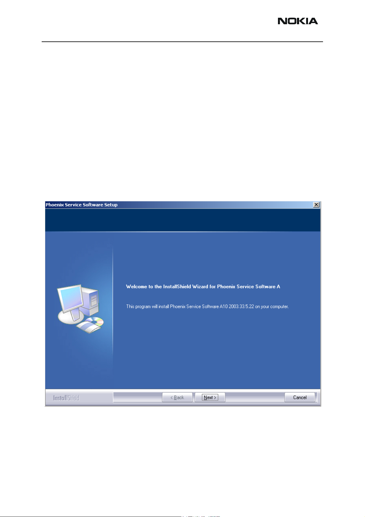
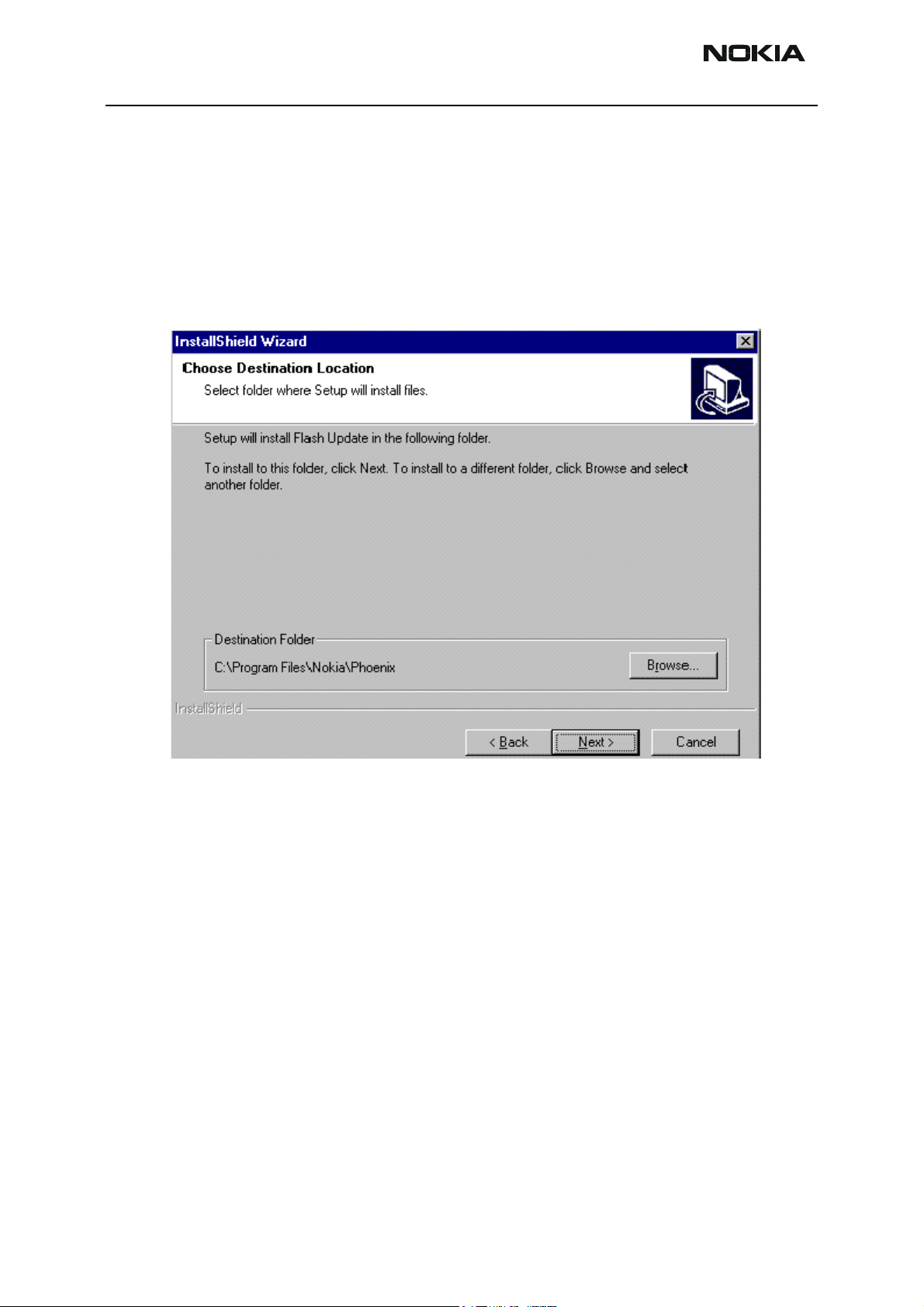
1 Double-click the phoenix_service_sw_a10_2003_33_5_22.exe icon.
The following welcome window appears:
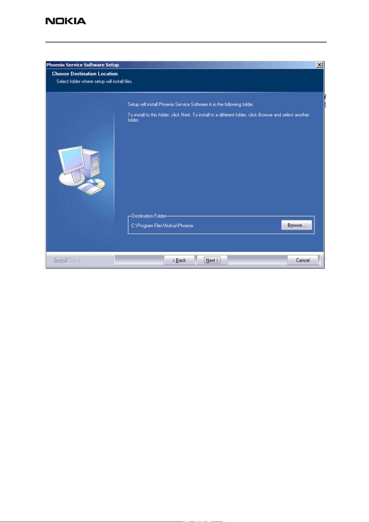
2 Choose the destination folder.
It is recommended to use the default folder. You can choose the destination
folder manually by clicking Browse, but this is not recommended.
Page 6 Copyright © 2004 Nokia Corporation Issue 1 05/04
Company Confidential
Page 7
Company Confidential RH-47
Nokia Customer Care 3 - Service Software Instructions
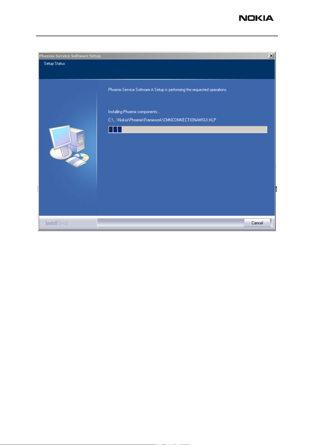
3 To continue, click Next.
Issue 1 05/04 Copyright © 2004 Nokia Corporation Page 7
Company Confidential
Page 8
RH-47 Company Confidential
3 - Service Software Instructions Nokia Customer Care
Install shield starts installing the Phoenix components. Please wait.
Page 8 Copyright © 2004 Nokia Corporation Issue 1 05/04
Company Confidential
Page 9
Company Confidential RH-47
Nokia Customer Care 3 - Service Software Instructions
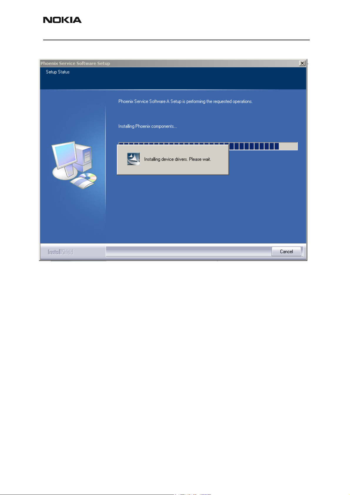
Install shield registers the Phoenix components. Please wait.
Issue 1 05/04 Copyright © 2004 Nokia Corporation Page 9
Company Confidential
Page 10

RH-47 Company Confidential
3 - Service Software Instructions Nokia Customer Care
4 When installation is finished, you get the following window:
To complete the installation, click Finish.
The installation of Phoenix service SW is ready and it can be used after:
• Installing the phone model specific data package
• Configuring the connections
Updating Phoenix
If you have already installed Phoenix on your PC, sooner or later there will be need to
update it when a new version is released.
Please note that very often the Phoenix Service SW and the phone specific data packages
for Phoenix come in pairs, meaning that a certain version of Phoenix can only be used
with a certain version of a data package. Always use the latest available versions of both.
Instructions can be found in the phone model specific technical bulletins.
To update Phoenix you need to take exactly the same steps as when installing it for the
first time:
1 Download the installation package.
2 Close all other programs.
Page 10 Copyright © 2004 Nokia Corporation Issue 1 05/04
Company Confidential
Page 11
Company Confidential RH-47
Nokia Customer Care 3 - Service Software Instructions
3 Run the installation package (e.g. phoenix_service_sw_a10_2003_33_5_22.exe).
Dongle driver is checked and if need be, updated.
If the dongle driver is updated the system reboots. After reboot installation starts
automatically.
The newer version of Phoenix is installed.
When you update Phoenix from old to new version (e.g. update from
2003_25_1_26 to 2003_33_5_22) installation takes place automatically without
uninstallation.
If you try to install an older version (e.g. downgrade from 2003_33_5_22 to
2003_25_1_26) installation will be interrupted.
If you try to update Phoenix with the same version that you already have (e.g.
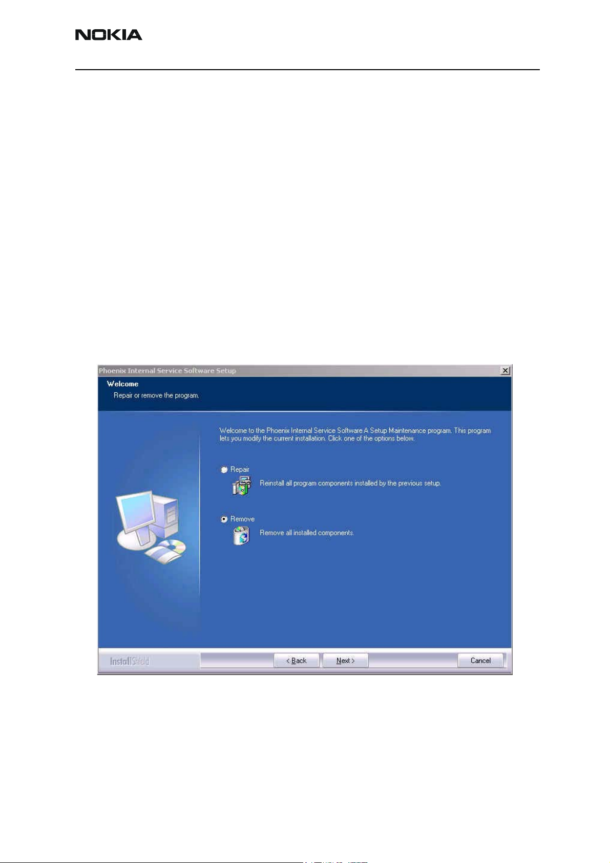
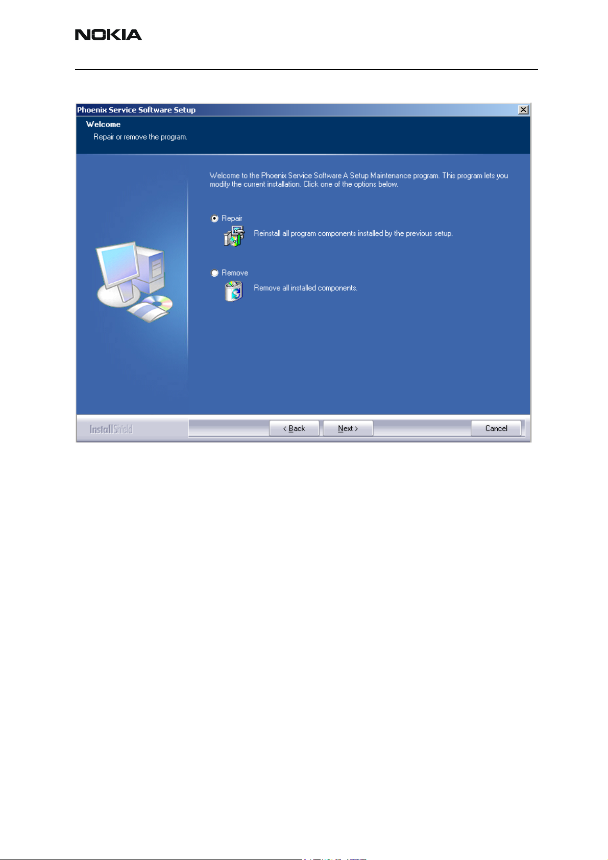
2003_33_5_22 to 2003_33_5_22) the following window will appear:
4 To uninstall Phoenix, click Next. Click Cancel to abort uninstallation.
If you want to reinstall Phoenix select the Repair button and click Next. Phoe-
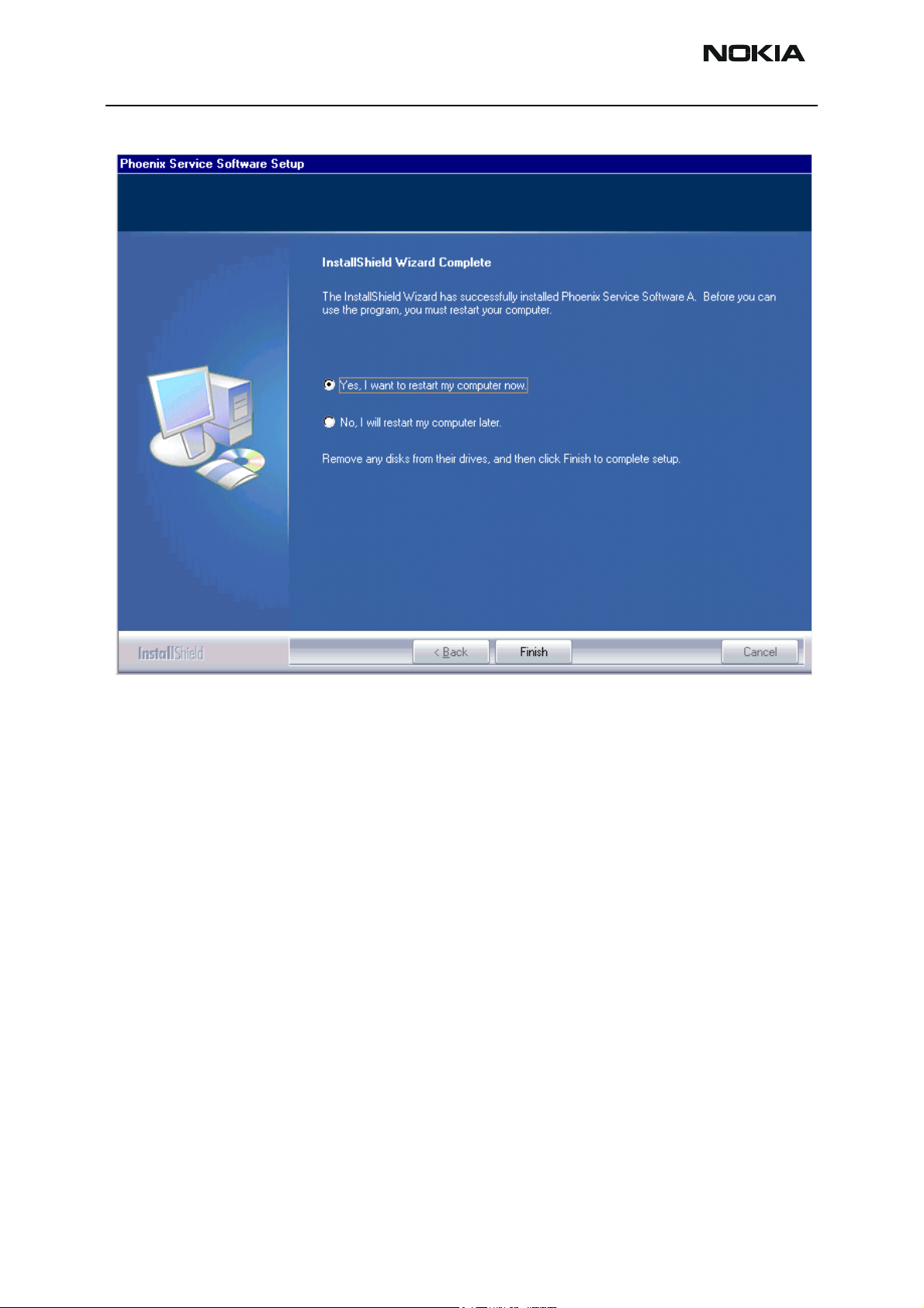
nix is installed again and you get the following window at the end of the rein-
Issue 1 05/04 Copyright © 2004 Nokia Corporation Page 11
Company Confidential
Page 12
RH-47 Company Confidential
3 - Service Software Instructions Nokia Customer Care
stallation:
5 To reboot the PC, click Finish.
Uninstalling Phoenix
To uninstall Phoenix manually from Windows:
1 Go to Control Panel and double-click Add/Remove Programs.
2 Select “Phoenix Service Software A” and click “Add/Remove”.
Page 12 Copyright © 2004 Nokia Corporation Issue 1 05/04
Company Confidential
Page 13
Company Confidential RH-47
Nokia Customer Care 3 - Service Software Instructions
The following window appears:
3 To uninstall, click Next.
The progress of the uninstallation is shown.
Issue 1 05/04 Copyright © 2004 Nokia Corporation Page 13
Company Confidential
Page 14

RH-47 Company Confidential
3 - Service Software Instructions Nokia Customer Care
4 After uninstallation, you have to reboot PC. Click Finish:
After restarting the PC, the uninstallation of Phoenix is finished.
Page 14 Copyright © 2004 Nokia Corporation Issue 1 05/04
Company Confidential
Page 15
Company Confidential RH-47
Nokia Customer Care 3 - Service Software Instructions
Software Update / Re-Flashing Setups
The following setup diagrams shows how to connect the different service devices when
flashing the RH-47 phone. Make sure that you have selected the right one before proceeding.
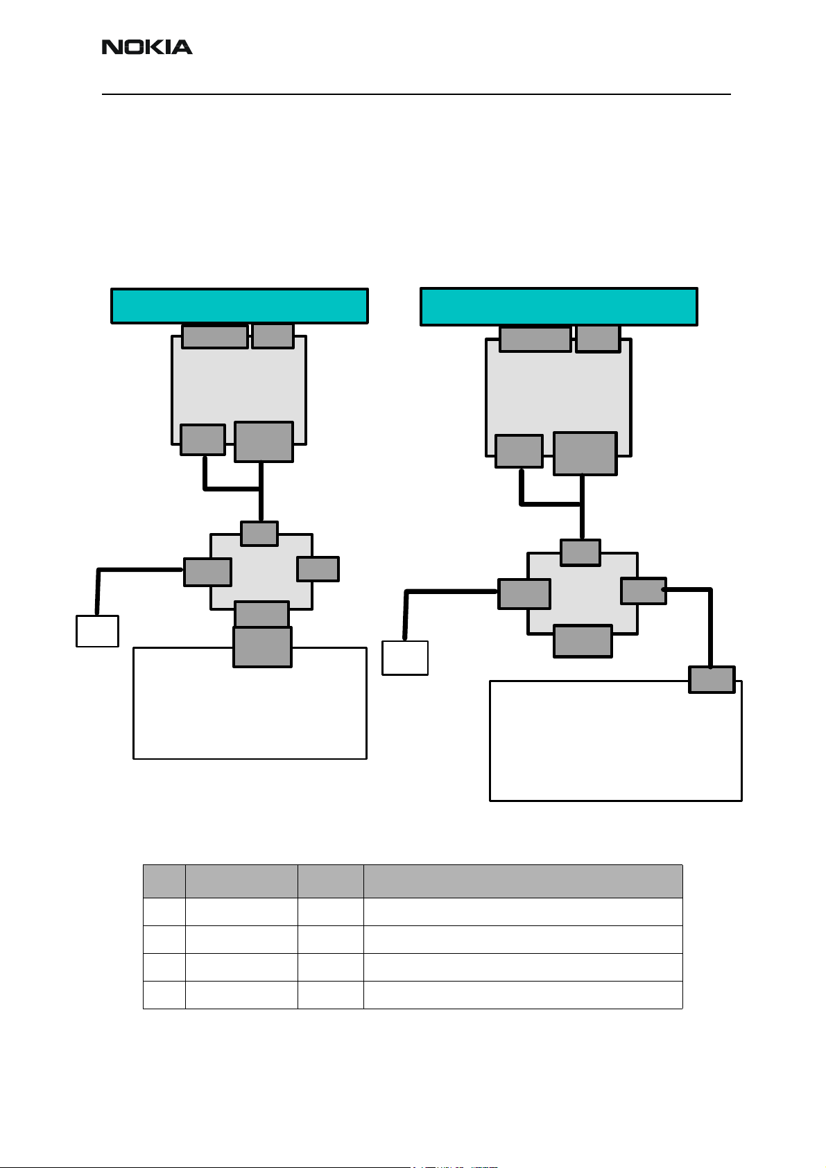
POS setup with FLS-4S
As a main interface either a USB or a parallel port can be used. See figures below:
ACF-8
Device Under Test
Test/Flash IF
Battery
SF-20
DC IN
ACF-8
MS Windows PC / Laptop
with Phoenix SW
Data
XCS-1
Phone
FLS-4S
LPT Port
LPT x
PORT
PC USB
ACF-8
Device Under Test
Test/Flash IF
Battery
SF-20
DC IN
ACF-8
MS Windows PC / Laptop
Data
XCS-1
Phone
FLS-4S
LPT Port
PC USB
with Phoenix SW
USB
cable
PC USB
Figure 1: USB interface setup Figure 2: Parallel port setup
Item Type designation Code Description
1 FLS-4S 0080543 POS flash prommer for US incl. ACF-8 Power supply
2 SF-20 0770702 POS flash adapter
3 XCS-1 0730218 Service cable with data & power connection for FLS-4S
4 ACF-8 0680032 Power Supply (Part of 0080543)
Issue 1 05/04 Copyright © 2004 Nokia Corporation Page 15
Company Confidential
Page 16
RH-47 Company Confidential
3 - Service Software Instructions Nokia Customer Care
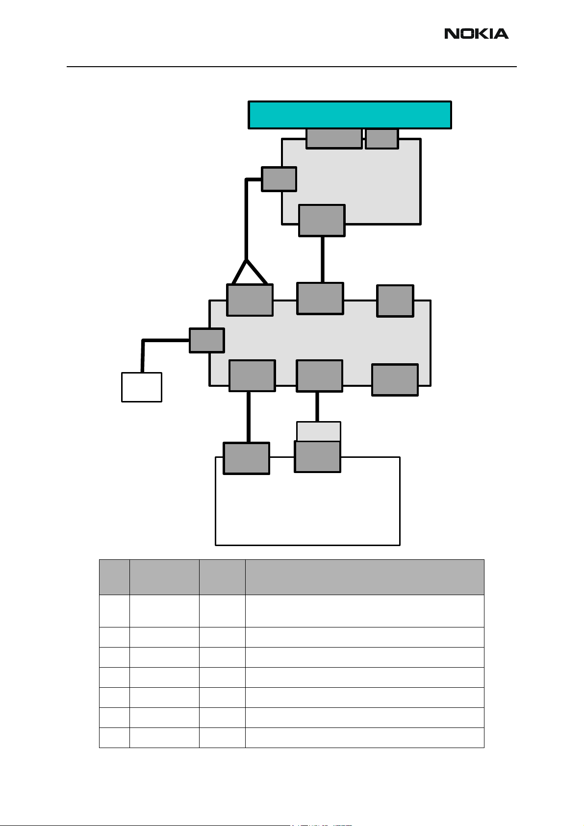
FPS-8 / SF-20 software update setup
Device Under Test
ACF-8
Power
FLC-2
AXS-4
Service
Battery
Serial
Input
DC IN
XCS-4
AXP-8
Test/Flash IF
SF-20
Data
Service
Cable
FPS-8
Parallel
Input
PKD-1x
Battery
IR
Phone
Connector
Item
1
2
3
4
5
6
Type
designation
Code Description
FPS-8 0080321
SF-20 0770702
FLC-2 0730185
AXS-4 0730090
ACF-8 0680032
AXP-8 0730298
COM x
PORT
LPT x
PORT
MS Windows PC / Laptop
Flash Prommer sales pack includes:ACF-8 power supply, AXS-4
service cable and AXP-8 Bi-directional parallel cable.
POS flash adapter
Power supply cable
Serial data cable 2x 9 pole Sub-D (Part of 0080321)
Power Supply (Part of 0080321)
Parallel printer cable (Part of 0080321)
XCS-4 0730178
7
Data cable
Page 16 Copyright © 2004 Nokia Corporation Issue 1 05/04
Company Confidential
Page 17
Company Confidential RH-47
Nokia Customer Care 3 - Service Software Instructions
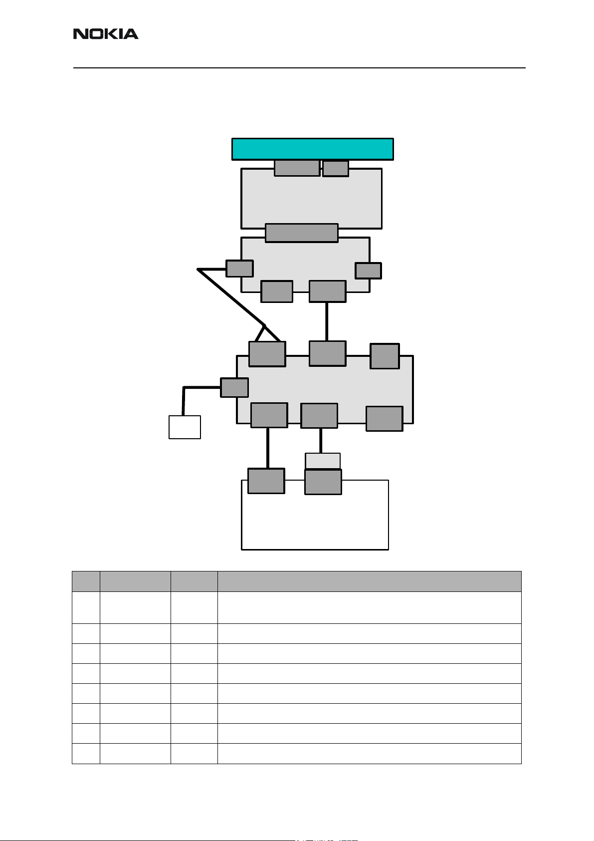
DA-17 software update setup
The usage of DA-17 for flashing under specific circumstances is possible. Note that the
phone is in “normal” mode after powered on.
Device Under Test
ACF-8
DC IN
PCS-1
Power
AXS-4
Service
Battery
Serial
Input
COM x
PORT
USB
Test/Flash IF
DA-17
Adapter Connector
(25 pol Sub-D)
JBV-1
DATA
XCS-4
Service
Cable
FPS-8
Parallel
Input
AXP-8
PKD-1x
LPT x
PORT
Battery
DC OUT
Connector
IR
Phone
MS Windows PC / Laptop
with Phoenix SW
Item Type designation Code Description
1 FPS-8 0080321 Flash Prommer sales pack includes: ACF-8 power supply, AXS-4 service
cable and AXP-8 Bi-directional parallel cable.
2 JBV-1 0770298 Docking station for testing & flashing
3 DA-17 0770701 Docking station adapter
4 PCS-1 0730012 Power cable
5 AXS-4 0730090 Serial data cable 2x 9 pole Sub-D (Part of 0080321)
6 ACF-8 0680032 Power Supply (Part of 0080321)
7 AXP-8 0730298 Parallel printer cable (Part of 0080321)
XCS-4
8
0730178 Data cable
Issue 1 05/04 Copyright © 2004 Nokia Corporation Page 17
Company Confidential
Page 18
RH-47 Company Confidential
3 - Service Software Instructions Nokia Customer Care
MJ-21 software update setup
Module repair jig flashing is possible with the following setup. Usually additional equipment is connected for further repair activities.
MJ-21
Main PWB
Battery
UI PWB&LCD
& Keypad
ACF-8
Power
Test/Flash IF
XCS-4
Service
Cable
FPS-8
Serial
Input
AXS-4
COM x
PORT
MS Windows PC / Laptop
with Phoenix SW
Parallel
Input
PKD-1x
LPT x
PORT
AXP-8
DC IN
PCS-1
Power Supply
4 V / 2A DC
Item Type designation Code Description
1 FPS-8 0080321 Flash Prommer sales pack includes: ACF-8 power supply, AXS-4 service cable
and AXP-8 Bi-directional parallel cable.
2 MJ-21 0770298 Module repair jig
4 PCS-1 0730012 Power cable
5 AXS-4 0730090 Serial data cable 2x 9 pole Sub-D (Part of 0080321)
6 ACF-8 0680032 Power Supply (Part of 0080321)
7 AXP-8 0730298 Parallel printer cable (Part of 0080321)
8 XCS-4 0730178 Data cable
Page 18 Copyright © 2004 Nokia Corporation Issue 1 05/04
Company Confidential
Page 19

Company Confidential RH-47
Nokia Customer Care 3 - Service Software Instructions
Connecting FPS-8 to PC
To establish a connection between your PC and FPS-8:
1 Connect FPS-8 to the PC as shown in the diagrams above (no phone is needed at
this step)
2 Start Phoenix.
3 From the File menu, choose Manage Connections.
4 Click Add.
5 Select Manual.
6 Select FPS-8.
7 Select the port where you have connected the serial cable of FPS-8.
8 In COMBOX_DEF_MEDIA, select FBUS.
9 Click Finish.
10 Click Arrow up key until FPS8 COM1 FBUS becomes the first on the list.
11 Click Apply and close the window.
The connection between the PC and FPS-8 is configured.
Activating FPS-8
Follow the instructions inside the FPS-8 sales package to activate FPS-8.
Checking application software version inside FPS-8
When you have established a connection to FPS-8 and it has been activated, the first
thing to do is to check that you have the correct application software version inside the
FPS-8. Phoenix software can check this automatically. The procedure goes as follows:
1 Go to a partner web site and download the latest AMS FPS-8 software.
To check the application software version:
2 Click FPS-8 downloads.
3 Click Flash Update.
4 Click AMS/Production version.
5 Click the latest version (xx . xx . xxx)
Issue 1 05/04 Copyright © 2004 Nokia Corporation Page 19
Company Confidential
Page 20
RH-47 Company Confidential
3 - Service Software Instructions Nokia Customer Care
6Save the file flash_update_xx_xx_xxx.exe to your hard drive to a place which
you can remember.
7 Go to that directory and double-click flash_update_xx_xx_xxx.exe.
You see the following note on your screen. Install files to the directory which installation
the program suggests you.
Figure 1: Install Shield Wizard screen
When the installation has been finished, FPS-8 files are located in that directory.
You can now start Phoenix software.
When Phoenix software has started, do the following:
1 From the Flashing menu, choose FPS-8/FPS-8C Maintenance.
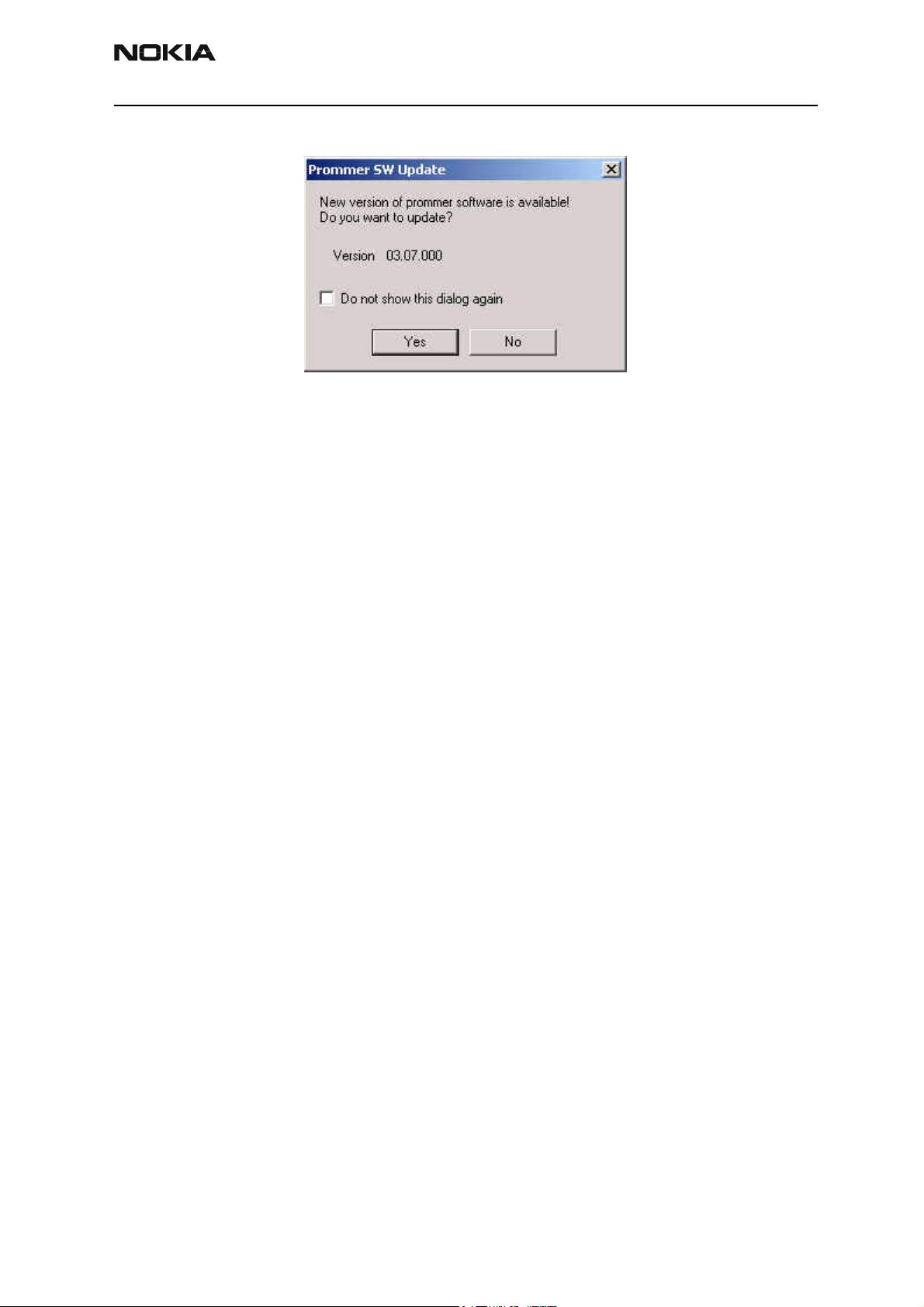
2 If software inside the FPS-8 prommer is too old, you will get the following notifi-
cation:
Page 20 Copyright © 2004 Nokia Corporation Issue 1 05/04
Company Confidential
Page 21
Company Confidential RH-47
Nokia Customer Care 3 - Service Software Instructions
Figure 2: Prommer software update screen
3 Click Yes.
On the small screen you see as the prommer goes to the service mode (mode2 is lit).
Application software, secondary boot codes and algorithm codes are updated.
Your PC and FPS-8 are now ready for the RH-47 software update.
Issue 1 05/04 Copyright © 2004 Nokia Corporation Page 21
Company Confidential
Page 22
RH-47 Company Confidential
3 - Service Software Instructions Nokia Customer Care
RE-Flashing Procedure
Flashing with FPS-8
First ensure that all cables are connected according to one of the diagrams above
(depending on the case)! See the respective chapter about connecting FPS-8 to a PC.
To flash the phone:
1 Start Phoenix.
Ensure that the latest AMS version of Phoenix is installed (Help -> About Phoenix).
If a newer version is available you must install it (see Updating Phoenix).
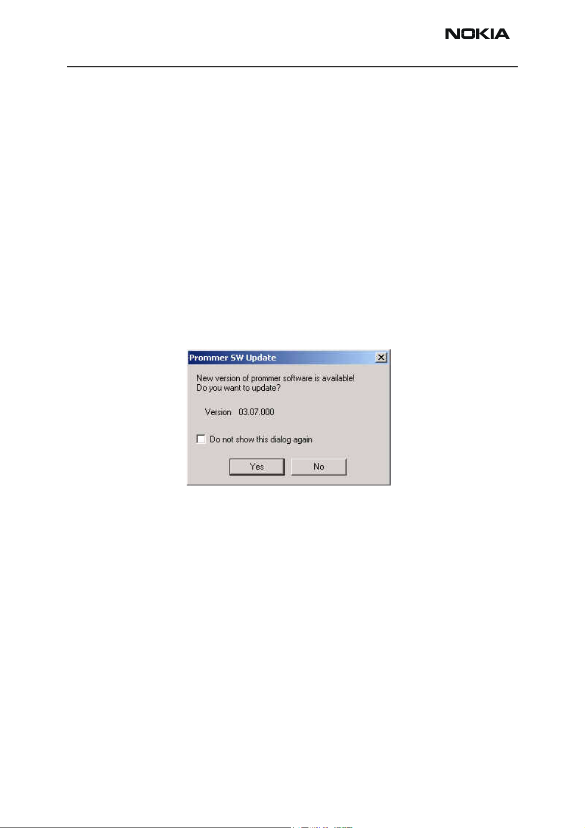
2 From the Flashing menu, choose FPS-8 Maintenance.
If the firmware in FPS-8 is old, you will get the following message:
3 Click Yes and wait until the prommer is updated.
Now you are ready to flash the phone.
4 Remove the SIM card and MMC card from the phone.
5 Turn the phone ON.
6 To scan the phone, press Ctrl + R (Make sure that the phone is loaded: the phone
type as well as the software version should be displayed in the status bar):
If no product is found, then choose RH-47 manually: File -> Open Product ->
RH-47.
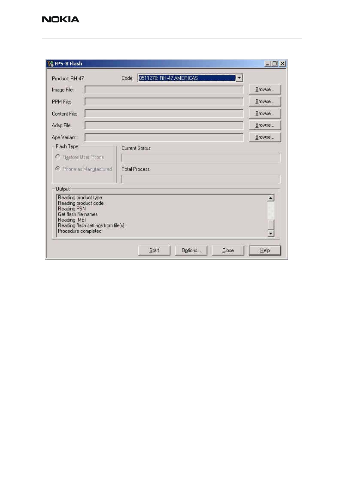
7 From the Flashing menu, choose FPS-8 Flash.
Page 22 Copyright © 2004 Nokia Corporation Issue 1 05/04
Company Confidential
Page 23
Company Confidential RH-47
Nokia Customer Care 3 - Service Software Instructions
The following window appears:
Ensure that there is a data package installed: in this case the MCU, PPM and
content package files are displayed automatically in the respective fields. Otherwise install a data package file (see related chapter).
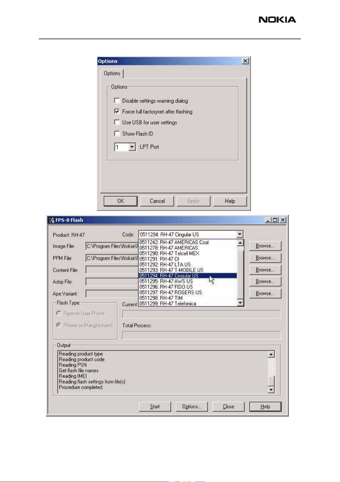
8 In the Options window, check the “Force full factoryset after flashing” check
Issue 1 05/04 Copyright © 2004 Nokia Corporation Page 23
Company Confidential
Page 24
RH-47 Company Confidential
3 - Service Software Instructions Nokia Customer Care
box:_
Page 24 Copyright © 2004 Nokia Corporation Issue 1 05/04
Company Confidential
Page 25

Company Confidential RH-47
Nokia Customer Care 3 - Service Software Instructions
(A) In case a data package is installed:
From the Product Code drop-down menu, choose the software variant you want
to flash.
Click Start.
(B) In case no data package is installed:
Click Browse.
Choose manually the desired MCU, PPM and Content Package files.
Click Start.
If an error message appears at the end of the flash process:
“Turn the power on and select OK”
Disconnect the phone completely.
Connect the phone again.
Press the power button of the phone and wait about 15 seconds.
Click OK.
If the phone does not turn on, then the MCU software version does not match
the phone’s HW and software update is not possible.
After the phone is successfully flashed, the user memory area should be formatted.
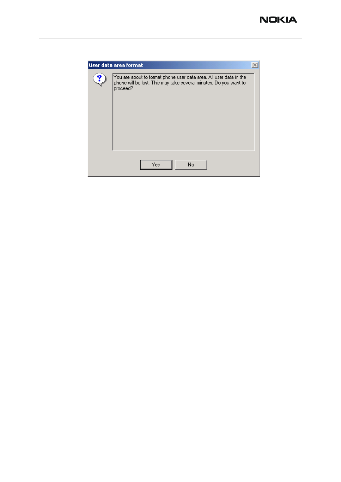
9 From the Product menu, choose User Data Area Format.
Issue 1 05/04 Copyright © 2004 Nokia Corporation Page 25
Company Confidential
Page 26
RH-47 Company Confidential
3 - Service Software Instructions Nokia Customer Care
The following window appears:
10 Click Yes and wait until you get a confirmation that the user area is successfully
formatted.
Flashing with FLS-4S
Make sure that you have the latest FLS-4S driver installed (in Windows: Settings -> Control: Panel -> FLS virtual port).
The flashing process is the same as with FPS-8:
1 Connect all cables of FLS-4S as shown in the diagrams presented in section POS
setup with FLS-4S adapter (use either a parallel port or USB).
2 Disconnect FPS-8 completely from the PC.
3 From the Flashing menu, choose FLS-4S Flash.
Repeat the steps presented in the previous section (FPS-8 flashing).
Page 26 Copyright © 2004 Nokia Corporation Issue 1 05/04
Company Confidential
Page 27

Company Confidential RH-47
Nokia Customer Care 3 - Service Software Instructions
Installing Data Package
A product data package contains all product specific data to make the Phoenix service
SW and tools usable with a certain phone model.
It also includes the latest version of flash update package for FLS-4S and FPS-8.
Before installation:
• Check that the dongle is attached to the parallel port of your computer.
• Find out whether there is a data package installed in Windows: Settings > Control Panel-> Add Remove programs.
• If the current data package is old, please remove it. Then download the
latest data package for RH-47 e.g. RH-
47_dp_v_x_xx_MCUSWx_xx.exe.
• Close all other programs.
To start installation:
1 Double-click the installation file (e.g. RH-47_dp_v_x_xx_MCUSWx_xx.exe).
The following window appears:
Issue 1 05/04 Copyright © 2004 Nokia Corporation Page 27
Company Confidential
Page 28

RH-47 Company Confidential
3 - Service Software Instructions Nokia Customer Care
2 To continue, click Next:
3 In the RH-47 Phone Data Package Setup window, you can see the contents of the
data package. Read this text carefully (there is information about the Phoenix
version needed with this package) and click Next:
Page 28 Copyright © 2004 Nokia Corporation Issue 1 05/04
Company Confidential
Page 29

Company Confidential RH-47
Nokia Customer Care 3 - Service Software Instructions
4 Confirm location and click Next to continue:
Phone model specific files are installed. Please wait.
Issue 1 05/04 Copyright © 2004 Nokia Corporation Page 29
Company Confidential
Page 30

RH-47 Company Confidential
3 - Service Software Instructions Nokia Customer Care
5 To complete installation, click Finish.
You now have all phone model specific files installed on your PC.
Uninstalling data package
You can uninstall the data package manually from Windows: Control Panel-> Add/
Remove Programs/RH-47 Phone data package.
If you try to install the same version of the data package that you already have, you are
asked if you want to uninstall the current version. Click OK to uninstall and Cancel if you
do not want to uninstall.
If you try to install a version that is newer than the currently installed one, there is no
need for uninstalling.
Page 30 Copyright © 2004 Nokia Corporation Issue 1 05/04
Company Confidential
Page 31

Company Confidential RH-47
Nokia Customer Care 3 - Service Software Instructions
The uninstallation progress is shown. In the end the following window appears:
To complete uninstallation, click Finish.
Issue 1 05/04 Copyright © 2004 Nokia Corporation Page 31
Company Confidential
Page 32

RH-47 Company Confidential
3 - Service Software Instructions Nokia Customer Care
Phoenix Self Tests
Self tests are divided into two categories:
• Startup self-test
• Triggered/called self-test
The startup procedure performs a self-test and the results are stored at every startup /
switch on of the phone. When the Phoenix menu is opened, the stored results from the
last startup are displayed.
The tests already performed are marked with “Yes” in the “Startup Test” column.
Figure 3: Phoenix Self Tests window
You can select specific tests by checking the “Test Name” check-box next to a test. To
start the test(s) you selected, click the “Start” button.
Alternatively, you can perform all tests by clicking the “Select All” button. For all tests,
RH-47 should be in the “Local” operating mode.
Note: For RH-47, the following two tests can only performed as a single test:
• ST_EXTERNAL_RAM_TEST
• ST_LCD_TEST
Page 32 Copyright © 2004 Nokia Corporation Issue 1 05/04
Company Confidential
Page 33

Company Confidential RH-47
Nokia Customer Care 3 - Service Software Instructions
The tests will get a “Timeout” or “Failed” status, if selected and performed at the same
time with other tests.
Issue 1 05/04 Copyright © 2004 Nokia Corporation Page 33
Company Confidential
Page 34

RH-47 Company Confidential
3 - Service Software Instructions Nokia Customer Care
Phoenix Tuning
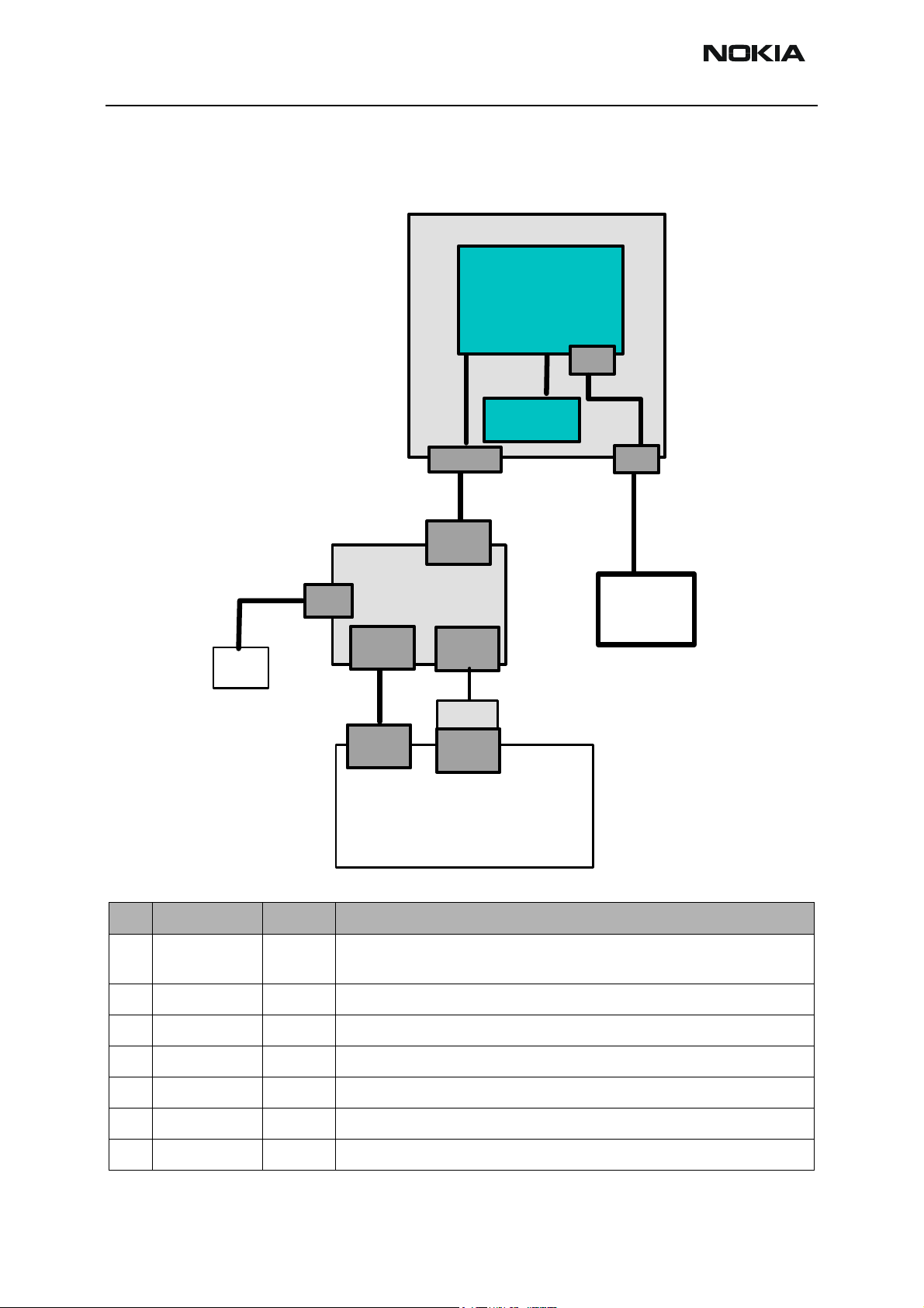
Energy management calibration
Energy Management calibration is a baseband tuning operation.
EM calibration should be carried out in a JBV-1 docking station equipped with a DA-17
docking station adapter.
Power to the JBV-1 should be supplied from an external power supply, not
8 prommer!
Connect the RH-47 phone as shown in the following diagram:
Power supply
12V DC / 1A
PCS-1
DC IN
Power
Device Under Test
Test/Flash IF
Adapter Connector
(25 pol Sub-D)
JBV-1
USB
Service
Battery
DA-17
XCS-4
FPS-8
Battery
DATA
Service
Cable
DC IN
CA-5S
DC OUT
IR
from the FPS-
ACF-8
AXS-4
Serial
Input
COM x
PORT
AXP-8
Parallel
Input
PKD-1x
LPT x
PORT
Phone
Connector
MS Windows PC / Laptop
with Phoenix SW
Type
Item
designation
Code Description
1 DA-17 0770701 Docking Station adapter for JBV-1
2 JBV-1 0770298 Flash/Test docking station with generic data & power inter-
faces.
Page 34 Copyright © 2004 Nokia Corporation Issue 1 05/04
Company Confidential
Page 35

Company Confidential RH-47
Nokia Customer Care 3 - Service Software Instructions
3 PCS-1 0730012 Power cable to connect e.g. JBV-1 to FPS-8.2 x Banana con-
nectors to 5,5 mm DC plug
4 XCS-4 0730178 Modular cable for e.g. connection between FPS-8 and SF-
20.
5 FPS-8 0080321 Flash Prommer to be used with SF-20 or JBV-1 plus product
specific adapter.
6 AXS-4 0730090 Data cable 2x 9 pole Sub-D male/female (Part of 0080321)
7 AXP-8 0730298 Bi-directional parallel data cable (Part of 0080321)
8 ACF-8 0680032 Power Supply (Part of 0080321)
Before proceeding, make sure that you have a working connection between FPS-8 and
the PC as described in the respective chapter.
To start Energy Management Calibration:
1 Start Phoenix.
2 Supply voltage in the range 11- 1 5 V from an external power supply to DC IN of
JBV-1.
3 The phone starts up in local mode automatically.
4 To scan the phone, press Ctrl+R.
Make sure that the phone is successfully loaded: you should see “SW version,
date, RH-47” in the Phoenix status bar.
5 From the Tuning menu, choose Energy Management Calibration.
Issue 1 05/04 Copyright © 2004 Nokia Corporation Page 35
Company Confidential
Page 36

RH-47 Company Confidential
3 - Service Software Instructions Nokia Customer Care
The following window appears:
6 To show the current values in the phone memory and to check that communica-
tion with the phone works, click Read From Phone.
7 Check all calibrations (Battery Size, Battery Voltage etc.).
8 Click Calibrate and wait until Calibrated appears in the status line.
9 If values are within limits, click “Save To Phone” to save the calibrated values.
Values written to phone appear in the status line.
Note! Only the values of the checked tunings are saved!
10 To verify that the new values are saved, click Read From Phone.
11 To end the tuning process, close the Energy Management Calibration dialog.
12 After exiting the Energy Management Calibration dialog, you must manually
switch the phone ON.
Page 36 Copyright © 2004 Nokia Corporation Issue 1 05/04
Company Confidential
Page 37

Company Confidential RH-47
Nokia Customer Care 3 - Service Software Instructions
Rx/Tx Tuning
One of the following setups is needed to perform tunings in Phoenix, depending on the
case and available equipment. Testing equipment can either be a single RX/TX testsystem
or two separate RX/TX test systems by using a RF coupler.
Issue 1 05/04 Copyright © 2004 Nokia Corporation Page 37
Company Confidential
Page 38

RH-47 Company Confidential
3 - Service Software Instructions Nokia Customer Care
RF tuning setup DA-17
JXS-2 shielded box
Device Under Test
GSM/RF
Tester
GPIB cable
RF- I/O
XRS-6
PCS-1
Power Supply
4 V / 2A DC
ACF-8
BT
(SMA)
RF
(SMA)
DC IN
Power
BT coupler
Service
Battery
Serial
Input
AXS-4
COM x
PORT
RF coupler
Adapter Connector
(25 pol Sub-D f)
JBV-1
USB
FPS-8
AXP-8
DA-17
XCS-4
Service
Parallel
Input
PKD-1x
LPT x
PORT
DATA
Cable
Test/Flash IF
SIM
cardreader
DC OUT
SIM
GPIB card
MS Windows PC / Laptop
with Phoenix SW
Item
Type
designation
Code Description
1 DA-17 0770701 Docking Station adapter for JBV-1
2 JBV-1 0770298 Flash/Test docking station with generic data & power interfaces.
3 PCS-1 0730012 Power cable to connect e.g. JBV-1 to power supply.2 x Banana connec-
tors to 5,5 mm DC plug
4 XCS-4 0730178 Modular cable for e.g. connection between FPS-8 and SF-20.
5 FPS-8 0080321 Flash Prommer to be used with SF-20 or JBV-1 plus product specific
adapter.
6 AXS-4 0730090 Serial cable 9 pole Sub-D - part of FPS-8 sales package!
7 AXP-8 0730298 Parallel bi-directional printer cable - part of FPS-8 sales package!
8 ACF-8 0680032 Power Supply – part of FPS-8 sales package!
Page 38 Copyright © 2004 Nokia Corporation Issue 1 05/04
Company Confidential
Page 39

Company Confidential RH-47
Nokia Customer Care 3 - Service Software Instructions
MJ-21 tuning setup
Headset
GSM/RF
Tester
RF- I/O
XRS-6
BT coupler
RF coupler
Zocus
+VBat
Zocus
GND
Charger
Loudsp.
MJ-21
UI PWB&LCD
Test/Flash IF
Main PWB
& Keypad
Mic
Battery
Ear
Local
Normal
DC IN
SIM
Reader
MMC
Reader
SIM
MMC
GPIB cable
XCS-4
ACF-8
Power
GPIB card
Service
Battery
FPS-8
Serial
Input
AXS-4
COM x
PORT
MS Windows PC / Laptop
Service
Cable
AXP-8
PKD-1x
with Phoenix SW
Item Type designation Code Description
Parallel
Input
LPT x
PORT
PCS-1
Power Supply
4 V / 2A DC
1 MJ-21 0770646 Module repair jig
2 XCS-4 0730178 Modular cable for e.g. connection between FPS-8 and SF-20.
3 PCS-1 0730012 Power cable to connect e.g. JBV-1 to FPS-8.2 x Banana connec-
tors to 5,5 mm DC plug
4 FPS-8 0080321 Flash Prommer to be used with SF-20 or JBV-1 plus product
specific adapter.
5 AXS-4 0730090 Serial cable 9 pole Sub-D - part of FPS-8 sales package!
Issue 1 05/04 Copyright © 2004 Nokia Corporation Page 39
Company Confidential
Page 40

RH-47 Company Confidential
3 - Service Software Instructions Nokia Customer Care
6 AXP-8 0730298 Parallel bi-directional printer cable - part of FPS-8 sales pack-
age!
7 ACF-8 0680032 Power Supply – part of FPS-8 sales package.
Start tuning with Phoenix:
1 Connect the phone to a PC running Phoenix service software with one of the set-
ups described.
2 Start Phoenix service software and open an FBUS connection: From the File
menu, choose Scan Product.
Wait until phone information is shown in the lower right corner of the screen.
RF tuning after repairs
Different repairs require different tunings. In general, it is necessary to determine in
which section the repair was done to select which tunings to perform. To determine if an
RF tuning is necessary after a repair, it is important that the functionality of the repaired
circuit is understood well. It is recommended to perform a complete RF tuning, if RF is
repaired.
• In general repairs, the TX part requires "TX Power Level Tuning" and "TX IQ
Tuning".
• In general repairs, the RX part or PLL part always require "RX Calibration",
“Rx Band Filter Response Calibration”.
• If Mjoelner is changed, all calibrations have to be done.
Other parts interfacing to TX, RX or PLL might require tuning, but common sense should
be used. For example, if a component that has no influence on the RF performance has
been changed, such as the microphone, on/off key, mechanical parts or similar, there is
no need to do any RF tunings.
Below is a list of needed activities related to changed component:
Exchanged Component IMEI re-writing EM calibration RF tuning
D190 - UEM YES NO NO
D311 - Flash 1 YES YES YES
D312 - Flash 2 NO NO NO
D310 - SDRAM NO NO NO
D100 - UPP NO NO NO
N601 - RF ASIC NO NO YES
N801 - RF PA NO NO YES
N430 - BT MCM NO NO NO
Page 40 Copyright © 2004 Nokia Corporation Issue 1 05/04
Company Confidential
Page 41

Company Confidential RH-47
Nokia Customer Care 3 - Service Software Instructions
Rx channel select filter calibration
This procedure calibrates the baseband filter inside Mjoelner. It is done by internally
measuring a prototype filter. For this reason the calibration is done once, not separately
in all three bands. No signal must be fed from an external signal generator
To start the calibration:
1 Launch Phoenix.
2 Set the phone in local mode.
3 From the Tuning menu, choose Rx Channel Select Filter Calibration.
The following window appears. If you do not want to save the newly calibrated
values in the phone, uncheck the “Save to Phone” check box (e.g. for testing purposes) before proceeding:
.
4 Click Start and then the Tune button.
The optimal values for GSM 850 are found.
5 To complete tuning, click Stop.
RX calibration (incl. VCXO-calibration)
Rx calibration is used to determine gain at different gain-settings for front-end and
Mjoelner and needs to be done in both bands (GSM 850 and GSM 1900). A signal generator is needed!
Calibration is automatically performed first at GSM850 and then at the GSM1900 band.
If tuning is successful, tuning continues at the next band. Calibration must be done separately on each band.
RX calibration in GSM850 combines two tunings: VCXO calibration and AGC calibration.
Issue 1 05/04 Copyright © 2004 Nokia Corporation Page 41
Company Confidential
Page 42

RH-47 Company Confidential
3 - Service Software Instructions Nokia Customer Care
The calibration of the GSM1900 band only determines AGC values.
Remember to take jig and cable attenuations into account when entering the power levels.
The VCXO-calibration finds out a calibration values for VCXO, an AFC initial value and
AFC slope coefficients.
A value (RF_TEMP), which represents the RF hardware temperature, is determined during
RX calibration. This temperature value is used by DSP to RSSI reporting in the normal
mode of the phone. It is not visible in the calibration process. Note that calibration must
be done between 22°..36°
AGC-calibration
The AGC-calibration finds the gain values of the RX-gain system. The AGC consists of RF
LNA, which can be either on or off (gain difference between on and off state is nominally
30 dB) and BB gain, which can be controlled, in 6 dB steps. This gives 15 gain steps RSSI0
to RSSI14. LNA is off for steps RSSI0 to RSSi4.
AFC-calibration measures the gain at gain step RSSI4 and RSSI7. The other gain values
are calculated.
VCXO-calibration
The VCXO-calibration ensures the function of an initial synchronization (before location
update), when the mobile station is in normal mode. For an error free initial synchronization, the 26 MHz frequency of the VCXO must be accurate enough. Therefore, a VCXO cal
value is written into the RefOSCCAL register of the Mjoelner.
During VCXO-calibration, the VCXO cal value is changed by a DSP-algorithm until synchronization is possible. This means that the VCXO oscillates at 26 MHz with a sufficient
minimum frequency error.
To further minimize the frequency error, an initial AFC-value is determined by the DSP
and written into RefOSCAFC register of the Mjoelner.
Also the DSP algorithm determines 3 AFC slope coefficients Slope C1.3 during VCXO calibration.
One AFC slope value is not sufficient for Mjoelner, because the AFC slope is non-linear in
this chip.
Page 42 Copyright © 2004 Nokia Corporation Issue 1 05/04
Company Confidential
Page 43

Company Confidential RH-47
Nokia Customer Care 3 - Service Software Instructions
To start the tuning process:
1 From the Tuning menu, choose Rx Calibration.
The following window appears.
2 To start tuning, click Start.
Issue 1 05/04 Copyright © 2004 Nokia Corporation Page 43
Company Confidential
Page 44

RH-47 Company Confidential
3 - Service Software Instructions Nokia Customer Care
3 Set the Rf signal generator to the required GSM850 frequency and click OK:
Tuning values and ADC reading are shown. A typical result looks like this:
4 To proceed to GSM1900, click Save & Continue.
Page 44 Copyright © 2004 Nokia Corporation Issue 1 05/04
Company Confidential
Page 45

Company Confidential RH-47
Nokia Customer Care 3 - Service Software Instructions
5 Set the Rf signal generator to the required GSM1900 frequency and click OK:
Tuning values and ADC readings are shown. A typical result looks like this:
Issue 1 05/04 Copyright © 2004 Nokia Corporation Page 45
Company Confidential
Page 46

RH-47 Company Confidential
3 - Service Software Instructions Nokia Customer Care
6 Click “Save & Continue” and the following window appears:
7 To finish the tuning process, click OK.
RX AGC limits
The Rx calibration is only valid if it is within certain limits.
For the most recent limits, see RH-47 Production Testing Requirements.
If calibration is not within limits, there is a fault in the RX chain.
Below are the values for RSSI4 and RSSI7:
RSSI 4:
RSSI7:
band min typ max
GSM 850 81 86 91
GSM 1900 79 85 89
band min typ max
GSM 850 103 108 11 3
GSM 1900 100 104 110
Page 46 Copyright © 2004 Nokia Corporation Issue 1 05/04
Company Confidential
Page 47

Company Confidential RH-47
Nokia Customer Care 3 - Service Software Instructions
Rx band filter response compensation
Calibration is done automatically, starting with GSM850 and then continuing with
GSM1900.
Connect the phone according to the setup diagrams.
Note! Remember to perform “Rx calibration” before doing “Rx band filter response compensation”!
Remember to take jig and cable attenuations into account!
To start calibration:
1 From the Tuning menu, choose Rx Band Filter Response Compensation.
2 In the Tuning mode pane, select the Manual tuning mode button.
3 To start the tuning process, click Start.
Issue 1 05/04 Copyright © 2004 Nokia Corporation Page 47
Company Confidential
Page 48

RH-47 Company Confidential
3 - Service Software Instructions Nokia Customer Care
4 Supply 9 different frequencies to the phone.
The tuning starts at the GSM850 band and continues the same way for the
GSM1900 band.
5 Set the first required frequency and power level. Click OK:
6 Repeat the sequence 9 times, until all channels are done.
In the end, you should see the following window:
7 To proceed to the GSM 1900 band, click Save & Continue.
Page 48 Copyright © 2004 Nokia Corporation Issue 1 05/04
Company Confidential
Page 49

Company Confidential RH-47
Nokia Customer Care 3 - Service Software Instructions
8 Set the first required frequency and power level and click OK:
9 Repeat the sequence 9 times, until all channels are done.
In the end, you should see the following window:
10 To finish the Rx Band Filter Response Compensation, click Save & Continue.
Issue 1 05/04 Copyright © 2004 Nokia Corporation Page 49
Company Confidential
Page 50

RH-47 Company Confidential
3 - Service Software Instructions Nokia Customer Care
TX I/Q tuning
Tx IQ tuning allows changing the Tx I Dc Offset, Tx Q DC Offset, amplitude difference and
phase difference. It must be performed separately on each band.
Prerequisites:
• A spectrum analyzer is needed to perform this tuning.
• Connect the phone according to the setup diagrams.
• Changing from GSM850 to GSM1900 is done automatically.
• Use the default settings for Rx/Tx channel, Tx data type and Tx PA mode.
• Remember to take into account jig and cable attenuations!
To start tuning:
1 From the Tuning menu, choose Tx IQ Tuning.
The following window appears:
Page 50 Copyright © 2004 Nokia Corporation Issue 1 05/04
Company Confidential
Page 51

Company Confidential RH-47
Nokia Customer Care 3 - Service Software Instructions
2 Click Start and tuning starts at the GSM850 band:
3 Enter these settings in the spectrum analyzer and click OK.
Issue 1 05/04 Copyright © 2004 Nokia Corporation Page 51
Company Confidential
Page 52

RH-47 Company Confidential
3 - Service Software Instructions Nokia Customer Care
The spectrum analyzer shows a plot like this:
4 To move the slider, use “+” and “-“ keys.
5 To adjust the carrier signal to a minimum level (Marker 2), use the variables “Tx I
DC offset” and “Tx Q DC offset”.
The purpose of this tuning is to tune the suppressed carrier signal and the first
sidelobe signal to a minimum level (Marker 2 and Marker 3).
After tuning to the minimum the level difference between the peak levels at
marker 1 and marker 2 must exceed 30 dB.
Tuning is possible by using arrow keys on the keyboard. Pushing the sliders by
using the mouse is less sensitive.
Page 52 Copyright © 2004 Nokia Corporation Issue 1 05/04
Company Confidential
Page 53

Company Confidential RH-47
Nokia Customer Care 3 - Service Software Instructions
The spectrum analyzer shows a plot like this:
6 To adjust the +67kHz signal to a minimum level (Marker 3), use the variables
“Amplitude difference” and “Phase difference”.
After tuning to the minimum, the level difference between the peak levels at
marker 1 and 3 must exceed 40 dB.
Tuning is possible by using arrow keys on the keyboard. Pushing the sliders by
using the mouse is less sensitive.
Issue 1 05/04 Copyright © 2004 Nokia Corporation Page 53
Company Confidential
Page 54

RH-47 Company Confidential
3 - Service Software Instructions Nokia Customer Care
The spectrum analyzer now shows a plot like this:
Note! The optimal values for “Tx I and Q offset” and “Amplitude and phase difference” vary from phone to phone.
The GSM850 TX IQ tuning is now finished.
7 To proceed to the GSM1900 band, click Save & Continue.
8 Set the spectrum analyzer according to the pop-up window.
9 Repeat the same steps as with GSM850.
10 Click Save & Continue.
Page 54 Copyright © 2004 Nokia Corporation Issue 1 05/04
Company Confidential
Page 55

Company Confidential RH-47
Nokia Customer Care 3 - Service Software Instructions
11 To finish the tuning process, click OK.
Tx power level tuning
Prerequisites:
To start tuning:
1 From the Tuning menu, choose Tx Power Level Tuning.
• A spectrum analyzer is needed.
• Connect the phone according to the setup diagrams.
• Turn on the power meter function of the spectrum analyzer used!
Use attenuator in order not to overload the spectrum analyzer.
Note:
• With Tx power level tuning, the coefficients are adjusted for each power
level.
• Must be done separately on each band.
• Start power level tuning at GSM850, then continue at GSM1900 band.
• In GSM850 and GSM1900 bands the power level tuning is made only for
high PA mode.
• Remember to take into account jig and cable attenuations!
Issue 1 05/04 Copyright © 2004 Nokia Corporation Page 55
Company Confidential
Page 56

RH-47 Company Confidential
3 - Service Software Instructions Nokia Customer Care
The following window appears.
2 Click Start and tuning starts at the GSM850 band:
3 Make the required adjustments of the spectrum analyzer as shown in the picture
and click OK:
The coefficient table lists the power level coefficient, target dBm and DAC value
for each power level.
Page 56 Copyright © 2004 Nokia Corporation Issue 1 05/04
Company Confidential
Page 57

Company Confidential RH-47
Nokia Customer Care 3 - Service Software Instructions
4 To choose the power level tuned, use the up and down arrows or mouse.
The current power level is shown with inverse colors.
Tuning value can be adjusted with “-“ and “+” keys.
GSM850: Tune base level and power levels 19, 15 and 5 according to target level.
The power levels may differ from Phoenix mentioned target power levels!
5 To proceed to the GSM1900 band, click Save & Continue.
6 Change the adjustments of the spectrum analyzer as shown in the picture and
Issue 1 05/04 Copyright © 2004 Nokia Corporation Page 57
Company Confidential
Page 58

RH-47 Company Confidential
3 - Service Software Instructions Nokia Customer Care
click OK:
GSM1900: Tune base level and power levels 15, 11 and 0 according to target
level.
The power levels may differ from Phoenix mentioned target power levels!
7 To end the tuning process, click Save & Continue.
Page 58 Copyright © 2004 Nokia Corporation Issue 1 05/04
Company Confidential
Page 59

Company Confidential RH-47
Nokia Customer Care 3 - Service Software Instructions
RF autotuning
Component autotuning is designed to align the product’s RF part easier and faster. It is
performed automatically by simply clicking the Tune button. The product’s Rf is tuned
and the results are shown to the user. The Autotune component controls all the needed
RF equipment (Rf generator and Tx measuring device), except the voltage supplier.
Autotuning is recommended for RH-47.
Autotune should be performed with JBV-1 and DA-17 inside a shielded box or with the
MJ-21 repair jig.
The losses for the DA-17 coupler, MJ-21 repair jig and those for the RF cables used must
be inserted in the “Set Loss” function of Phoenix.
Make sure that the GPIB card is initialized in Phoenix. To initialize the card, choose Tools
-> Options -> GPIB card. The cards number, address, and type should be displayed there.
Issue 1 05/04 Copyright © 2004 Nokia Corporation Page 59
Company Confidential
Page 60

RH-47 Company Confidential
3 - Service Software Instructions Nokia Customer Care
Setup Diagrams
Before proceeding with Autotune make sure you have one of the following setups built
up.
Figure 4: Autotune with DA-17 and a universal GSM/RF tester (e.g. CMU-200).
JXS-2 shielded box
Device Under Test
GSM/RF
Tester
GPIB cable
RF- I/O
XRS-6
PCS-1
Power Supply
4 V / 2A DC
BT
(SMA)
RF
(SMA)
DC IN
Power
BT coupler
USB
Service
Battery
RF coupler
DA-17
Adapter Connector
(25 pol Sub-D f)
JBV-1
DATA
XCS-4
Service
Cable
FPS-8
Test/Flash IF
SIM
cardreader
DC OUT
SIM
Parallel
Input
AXP-8
PKD-1x
LPT x
PORT
ACF-8
GPIB card
Serial
Input
AXS-4
COM x
PORT
MS Windows PC / Laptop
with Phoenix SW
Page 60 Copyright © 2004 Nokia Corporation Issue 1 05/04
Company Confidential
Page 61

Company Confidential RH-47
Nokia Customer Care 3 - Service Software Instructions
Type
Item
designation
1 DA-17 0770701 Docking Station adapter for JBV-1
2 JBV-1 0770298 Flash/Test docking station with generic data & power inter-
3 PCS-1 0730012 Power cable to connect e.g. JBV-1 to FPS-8.2 x Banana con-
4 XCS-4 0730178 Modular cable for e.g. connection between FPS-8 and SF-20.
5 FPS-8 0080321 Flash Prommer to be used with SF-20 or JBV-1 plus product
6 AXS-4 0730090 Serial cable 9 pole Sub-D - part of FPS-8 sales package!
7 AXP-8 0730298 Parallel bi-directional printer cable - part of FPS-8 sales pack-
Code Description
faces.
nectors to 5,5 mm DC plug
specific adapter.
age!
8 ACF-8 0680032 Power Supply – part of FPS-8 sales package.
9 XRS-6 0730231 RF cable to connect e.g. module repair jig to RF measurement
equipment. SMA to N-Connector ca. 610mm
10 NA NA GPIB cable
11 NA NA GPIB card for PC (National Instruments compatible)
12 JXS-2 0770673 Optional shielded box for RF autotuning and testing in specific
service environment in US.To be used with DA-1 adapter
Issue 1 05/04 Copyright © 2004 Nokia Corporation Page 61
Company Confidential
Page 62

RH-47 Company Confidential
3 - Service Software Instructions Nokia Customer Care
Figure 5: Autotune with MJ-21 and a universal GSM/RF tester (e.g. CMU-200)
GSM/RF
Tester
GPIB cable
RF- I/O
XRS-6
Service
Battery
BT coupler
RF coupler
Zocus
+VBat
Zocus
GND
Charger
Test/Flash IF
XCS-4
Headset
Service
Cable
Loudsp.
Main PWB
MJ-21
UI PWB&LCD
& Keypad
Mic
Battery
Ear
Local
Normal
DC IN
PCS-1
SIM
Reader
MMC
Reader
SIM
MMC
ACF-8
Power
GPIB card
FPS-8
Serial
Input
AXS-4
COM x
PORT
MS Windows PC / Laptop
with Phoenix SW
Parallel
Input
AXP-8
PKD-1x
LPT x
PORT
Power Supply
4 V / 2A DC
Page 62 Copyright © 2004 Nokia Corporation Issue 1 05/04
Company Confidential
Page 63

Company Confidential RH-47
Nokia Customer Care 3 - Service Software Instructions
Item
1 MJ-21 0770646 Module repair jig
2 XCS-4 0730178 Modular cable for e.g. connection between FPS-8 and SF-
3 PCS-1 0730012 Power cable to connect e.g. JBV-1 to FPS-8.2 x Banana con-
4 FPS-8 0080321 Flash Prommer to be used with SF-20 or JBV-1 plus product
5 AXS-4 0730090 Serial cable 9 pole Sub-D - part of FPS-8 sales package!
6 AXP-8 0730298 Parallel bi-directional printer cable - part of FPS-8 sales
7 ACF-8 0680032 Power Supply – part of FPS-8 sales package.
8 XRS-6 0730231 RF cable to connect e.g. module repair jig to RF measure-
9 NA NA GPIB cable
10 NA NA GPIB card for PC (National Instruments compatible)
Type
designation
Code Description
20.
nectors to 5,5 mm DC plug
specific adapter.
package!
ment equipment.
SMA to N-Connector ca. 610mm
Issue 1 05/04 Copyright © 2004 Nokia Corporation Page 63
Company Confidential
Page 64

RH-47 Company Confidential
3 - Service Software Instructions Nokia Customer Care
Figure 6: Autotune with DA-17 using RF Generator and RF Analyzer (e.g. Agilent VSA E4406 (Signal
analyzer) and Agilent ESG (Signal generator).
JXS-2 shielded box
Device Under Test
RF generator
RF Analyzer
GPIB cable
RF- I/O
RF- I/O
Splitter
XRS-6
Power Supply
4 V / 2A DC
Power
RF
(SMA)
DC IN
Service
Battery
RF coupler
DA-17
Adapter Connector
(25 pol Sub-D f)
JBV-1
USB
XCS-4
Service
Cable
FPS-8
DATA
Test/Flash IF
SIM
cardreader
DC OUT
SIM
ACF-8
GPIB card
Serial
Input
Parallel
Input
AXP-8
AXS-4
PKD-1x
COM x
PORT
LPT x
PORT
MS Windows PC / Laptop
with Phoenix SW
Page 64 Copyright © 2004 Nokia Corporation Issue 1 05/04
Company Confidential
Page 65

Company Confidential RH-47
Nokia Customer Care 3 - Service Software Instructions
Item
1 DA-17 0770701 Docking Station adapter for JBV-1
2 JBV-1 0770298 Flash/Test docking station with generic data & power inter-
3 PCS-1 0730012 Power cable to connect e.g. JBV-1 to FPS-8.2 x Banana con-
4 XCS-4 0730178 Modular cable for e.g. connection between FPS-8 and SF-20.
5 FPS-8 0080321 Flash Prommer to be used with SF-20 or JBV-1 plus product
6 AXS-4 0730090 Serial cable 9 pole Sub-D - part of FPS-8 sales package!
7 AXP-8 0730298 Parallel bi-directional printer cable - part of FPS-8 sales
8 ACF-8 0680032 Power Supply – part of FPS-8 sales package.
9 XRS-6 0730231 RF cable to connect e.g. module repair jig to RF measurement
10 NA NA GPIB cable
Type
designation
Code Description
faces.
nectors to 5,5 mm DC plug
specific adapter.
package!
equipment.
SMA to N-Connector ca. 610mm
11 NA NA GPIB card (National Instruments compatible)
12 JXS-2 0770673 Optional shielded box for RF autotuning and testing in spe-
cific service environment in US.To be used with DA-1 adapter
Issue 1 05/04 Copyright © 2004 Nokia Corporation Page 65
Company Confidential
Page 66

RH-47 Company Confidential
3 - Service Software Instructions Nokia Customer Care
Figure 7: Autotune with MJ-21 using RF generator and RF analyzer (e.g. Agilent VSA E4406 (Signal analyzer)
and Agilent ESG (Signal generator).
RF generator
RF Analyzer
RF- I/O
RF- I/O
Splitter
XRS-6
BT coupler
RF coupler
Zocus
+VBat
Zocus
GND
Charger
Test/Flash IF
Headset
Loudsp.
Main PWB
MJ-21
UI PWB&LCD
& Keypad
Mic
Battery
Ear
Local
Normal
DC IN
SIM
Reader
MMC
Reader
SIM
MMC
GPIB cable
ACF-8
Power
GPIB card
XCS-4
Service
Battery
Service
Cable
FPS-8
Serial
Input
AXS-4
COM x
PORT
MS Windows PC / Laptop
with Phoenix SW
Parallel
Input
AXP-8
PKD-1x
LPT x
PORT
PCS-1
Power Supply
4 V / 2A DC
Page 66 Copyright © 2004 Nokia Corporation Issue 1 05/04
Company Confidential
Page 67

Company Confidential RH-47
Nokia Customer Care 3 - Service Software Instructions
Item
1 MJ-21 0770646 Module repair jig
2 XCS-4 0730178 Modular cable for e.g. connection between FPS-8 and SF-
3 PCS-1 0730012 Power cable to connect e.g. JBV-1 to FPS-8.2 x Banana
4 FPS-8 0080321 Flash Prommer to be used with SF-20 or JBV-1 plus prod-
5 AXS-4 0730090 Serial cable 9 pole Sub-D - part of FPS-8 sales package!
6 AXP-8 0730298 Parallel bi-directional printer cable - part of FPS-8 sales
7 ACF-8 0680032 Power Supply – part of FPS-8 sales package.
8 XRS-6 0730231 RF cable to connect e.g. module repair jig to RF measure-
9 NA NA GPIB cable
10 NA NA GPIB card for PC (National Instruments compatible)
Type
designation
Code Description
20.
connectors to 5,5 mm DC plug
uct specific adapter.
package!
ment equipment.
SMA to N-Connector ca. 610mm
Autotune procedure
1 Start Phoenix.
2 From the Tuning menu, choose Auto-Tune:
Issue 1 05/04 Copyright © 2004 Nokia Corporation Page 67
Company Confidential
Page 68

RH-47 Company Confidential
3 - Service Software Instructions Nokia Customer Care
The following window appears:
3 Click Tune.
The phone turns to local mode automatically and autotune starts.
Wait until the tuning process has finished (about 1 minute). You see the follow-
Page 68 Copyright © 2004 Nokia Corporation Issue 1 05/04
Company Confidential
Page 69

Company Confidential RH-47
Nokia Customer Care 3 - Service Software Instructions
ing window:
4 To finish the tuning process close this window.
Issue 1 05/04 Copyright © 2004 Nokia Corporation Page 69
Company Confidential
Page 70

RH-47 Company Confidential
3 - Service Software Instructions Nokia Customer Care
Bluetooth Bit Error Rate Test
Hardware needed to use JBT-9
• JBT-9 Bluetooth test box
• SMA stub antenna (part of sales kit)
• ACP-8x charger (x denotes region, e.g. ACP-8E for Europe)
JBT-9 test box
The JBT-9 Bluetooth test box can be used without a PC connection as a loop-back device
for BT testing. To verify the products BT functionality, a Bit Error Rate test needs to be
performed against JBT-9. The test is controlled and executed by Phoenix service software.
JBT-9 test range
The JBT-9 test range is related to attenuation settings. The default factory setting of
internal attenuation results in a RF level of –36dBm. This reduces the RF range up to 0.5
m. In case that distance is too short to perform tests over the air, the internal attenuation can be changed as described in the chapter below.
In case a service jig is directly connected to the box SMA RF I/O connector via cable, it is
recommended to work also with the maximum internal attenuation (default factory setting).
Performing BER test
1 Connect service jig’s BT RF cable to JBT-9’s RF/IO connector. Optional with DA-
17; the JBT-9 stub antenna can be used instead of cable.
2 Connect an ACP-8x charger to JBT-9 power connector.
Make sure that distance between phone and JBT-9 does not exceed ~ 0.5 m distance
when using default attenuation setting.
BER test result is OK when BER is less than 0.1%
Note! The phone connection to the PC is specific to the tested phone. For details refer to the related
chapter in the service manual.
Page 70 Copyright © 2004 Nokia Corporation Issue 1 05/04
Company Confidential
Page 71

Company Confidential RH-47
Nokia Customer Care 3 - Service Software Instructions
BER test with DA-17
There are several options to perform the BER test, e.g. with a cable connection or JBT-9
antenna. The test setup used depends on environmental conditions and service level.
JXS-2 shielded box (optional)
ACF-8
Device Under Test
Test/Flash IF
DA-17
Adapter Connector
(25 pol Sub-D)
DC IN
USB
PCS-1
Service
Battery
Power
Serial
Input
Battery
JBV-1
FPS-8
coupler
XCS-4
BT
DATA
Service
Cable
Parallel
Input
RF
DC OUT
XRE-2
RF I/O
RS232
JBT-9
ACP-8
ACP-8x
AXS-4
PKD-1x
COM x
PORT
LPT x
PORT
MS Windows PC / Laptop
with Phoenix SW
Item Type designation Code Description
1 DA-17 0770701 Docking Station adapter for JBV-1
2 JBV-1 0770298 Flash/Test docking station with generic data & power interfaces.
3 PCS-1 0730012 Power cable to connect e.g. JBV-1 to FPS-8.2 x Banana connectors
to 5,5 mm DC plug
4 FPS-8 0080321 Flash Prommer to be used with SF-20 or JBV-1 plus product spe-
cific adapter.
5 AXS-4 0730090 Serial cable 9 pole Sub-D - part of FPS-8 sales package!
Issue 1 05/04 Copyright © 2004 Nokia Corporation Page 71
Company Confidential
Page 72

RH-47 Company Confidential
3 - Service Software Instructions Nokia Customer Care
6 ACF-8 0680032 Power Supply – part of FPS-8 sales package.
7 JBT-9 81490 Bluetooth Test & Interface Box
8 ACP-8E 0675195 Charger for JBT-9 Output: 5.3V DC, 500 mA; Europe. Version
Page 72 Copyright © 2004 Nokia Corporation Issue 1 05/04
Company Confidential
Page 73

Company Confidential RH-47
Nokia Customer Care 3 - Service Software Instructions
BER test with MJ-21
MJ-21 is another option to perform BER test on module level.
ACP-8
ACP-8
Max.6,3V
ACF-8
RS 232
JBT-9
RF- I/O
Power
XRE-2
BT coupler
FPS-8
Serial
Input
Test/Flash IF
XCS-4
Service
Cable
MJ-21
Main PWB
Battery
UI PWB&LCD
& Keypad
DC IN
PCS-1
Power Supply
4 V / 3A DC
Parallel
Input
AXS-4
COM x
PORT
LPT x
PORT
MS Windows PC / Laptop
with Phoenix SW
Item
Type designation Code Description
1 MJ-21 0770646
2 PCS-1 0730012 Power cable to connect e.g. JBV-1 to FPS-8.2 x Banana
connectors to 5,5 mm DC plug
3 FPS-8 0080321 Flash Prommer to be used with SF-20 or JBV-1 plus
product specific adapter.
4 AXS-4 0730090 Serial cable 9 pole Sub-D - part of FPS-8 sales package!
5 ACF-8 0680032 Power Supply – part of FPS-8 sales package.
Issue 1 05/04 Copyright © 2004 Nokia Corporation Page 73
Company Confidential
Page 74

RH-47 Company Confidential
3 - Service Software Instructions Nokia Customer Care
6 JBT-9 81490 Bluetooth Test & Interface Box
7 ACP-8 0675195 Charger for JBT-9 Output: 5.3V DC, 500 mA; Europe. Ver-
sion
Testing instructions for BER testing
1 Make sure that the phone’s product support modules are properly loaded by
Phoenix SW.
2 Set phone into Operating mode “TEST”
3 From the Testing menu, choose “Bluetooth LOCALS”.
4 Enter JBT-9’s Ser.No. (12 digits from the type label) in the field “Counterpart
Device Address”. This has only to be done once as long as JBT-9 is not changed!
Standard testing parameters as bit frames, hopping mode and number of bits are
default settings by Phoenix. BT Software Operational Mode = Normal Mode.
Page 74 Copyright © 2004 Nokia Corporation Issue 1 05/04
Company Confidential
Page 75

Company Confidential RH-47
Nokia Customer Care 3 - Service Software Instructions
5 To perform the BER test, click the “Run BER Test” button.
“Test done” means that test has successfully been performed; if Bit Error Rate is
</= 0.1% the “Result” will be also displayed as “OK”.
Additional menu functions
BT MCM related self-tests can be performed by clicking “Run Self Tests”. Results have to
be “PASSED”.
The “Version Information” dialog gives you BT MCM related detail information that could
be necessary in case of detailed fault reporting.
Other settings like “Scan Mode” or “BT Software Operational Mode” are only necessary to
change in case of special device analysis in combination with e.g. commercial BT testsystems.
JBT-9 attenuation setting via jumper
Internal possible settings for attenuation after JBT-9 boot-up are listed below. 29 dB is
default setting.
Attenuation Typical output power (+/- 5 dB) GPP10 GPP11 Typical RF range
14 dB - 21 dBm Closed (GND) Open < 1,5 m
14 dB - 21 dBm Open Closed (GND) < 1,5 m
0 dB - 7 dBm Open Open < 10 m
29 dB - 36 dBm Closed (GND) Closed (GND) < 0,5 m
Issue 1 05/04 Copyright © 2004 Nokia Corporation Page 75
Company Confidential
Page 76

RH-47 Company Confidential
3 - Service Software Instructions Nokia Customer Care
LED Indication of JBT-9
ACTION STATUS-LED BER TEST-LED FBUS-LED POWER-LED
POWER ON
FBUS ON
INQUIRY BLINKING
CONNECTED ON
BER-TEST ON
LOOP-BACK ON
ERROR ON RED
BOX READY ON GREEN
Page 76 Copyright © 2004 Nokia Corporation Issue 1 05/04
Company Confidential
Page 77

Company Confidential RH-47
Nokia Customer Care 3 - Service Software Instructions
Audio Test
Audio testing is used to test the integrated in the phone speakers as well as looping of
signals within predefined paths.
A headset is needed.
Audio test is performed using a MJ-21 module jig.
Setup diagram
The following setup is required to run audio test on engine board level.
Issue 1 05/04 Copyright © 2004 Nokia Corporation Page 77
Company Confidential
Page 78

RH-47 Company Confidential
3 - Service Software Instructions Nokia Customer Care
Item Type designation Code Description
1 MJ-21 0770646 Module repair jig
2 XCS-4 0730178 Modular cable for e.g. connection between FPS-8 and SF-
20.
3 PCS-1 0730012 Power cable to connect e.g. JBV-1 to FPS-8.2 x Banana
connectors to 5,5 mm DC plug
4 FPS-8 0080321 Flash Prommer to be used with SF-20 or JBV-1 plus prod-
uct specific adapter.
5 AXS-4 0730090 Serial cable 9 pole Sub-D - part of FPS-8 sales package!
6 AXP-8 0730298 Parallel bi-directional printer cable - part of FPS-8 sales
package!
7 ACF-8 0680032 Power Supply – part of FPS-8 sales package.
8 HS-7 0694228 Dual Mono Headset
Audio test procedure
1 Set the phone to TEST mode.
2 From the Testing menu, choose Audio Test.
Page 78 Copyright © 2004 Nokia Corporation Issue 1 05/04
Company Confidential
Page 79

Company Confidential RH-47
Nokia Customer Care 3 - Service Software Instructions
The following window appears:
The most important audio tests are: Hp in Ext out, Ext in Hp out and Ext in IHF out:
Hp in Ext out: the signal is routed from the phone’s microphone to an external speaker
(e.g. headset).
Ext in Hp out: the signal is routed from an external microphone (e.g. headset) to the
phone’s speaker.
Ext in IHF out: the signal is routed from an external microphone (e.g. headset) to the
integrated in the phone hands free speaker.
Issue 1 05/04 Copyright © 2004 Nokia Corporation Page 79
Company Confidential
Page 80

Company Confidential RH-47
Nokia Customer Care 3 - Service Software Instructions
Audio signal routing
Hp in Ext out
Speaker
AF out
Microphone
AF in
Ext. Headset
Ext in Hp out
Ext. Headset
Speaker
AF in
Microphone
Ext in IHF out RH-47
Ext. Headset
Speaker
Microphone
Microphone
Microphone
MALT
speaker
MALT
speaker
MALT
speaker
AF out
RH-47
Headset
Connector
RH-47
Headset
Connector
Headset
Connector
Earpiece
Earpiece
Earpiece
AF out
Micro-
AF in
phone
The order in which you perform the tests has no importance.
Test procedure:
1 Select a test from the list and click Loop ON.
2 Apply an acoustic signal to the respective input (e.g. when testing Hp in Ext out
you should apply an acoustic signal to the phone’s microphone).
3 The acoustic signal will be looped to the respective output. (e.g. when testing Hp
in Ext out you will hear the acoustic signal at the headset’s speaker)
4 During each test you can change the UEM output and input gain to several val-
Issue 1 05/04 Copyright © 2004 Nokia Corporation Page 80
Company Confidential
Page 81

Company Confidential RH-47
Nokia Customer Care 3 - Service Software Instructions
ues. This affects the volume of the routed signal.
5 To finish the testing process, close the Audio Test dialog.
Issue 1 05/04 Copyright © 2004 Nokia Corporation Page 81
Company Confidential
Page 82

RH-47 Company Confidential
3 - Service Software Instructions Nokia Customer Care
Phoenix Error Codes
Below is a list of some Phoenix errors that may come up, for example, during re-flashing
operations. The table also describes the possible root causes in HW.
Phoenix
Failure
Code
Phoenix Failure Description Possible Problems / Analysis Proposed Action
C686, C684 Phone fail response received This failure may occur during flash program-
ming.
When programming, the sequence is from
D311 (about 80s) to D312 (about 30s). When
erasing, the sequence is from D311 (about
130s) to D312 (about 70s). The position
reveals which device causes the failure. Also
check the chip enable signals during flashing
at J311 and J312.
C108 External RAM test failed SDRAM has a connectivity problem to UPP or
SDRAM power supplies missing. Probably a
defect component. Before changing the component check SDRAM power supplies (VIO)
and the clock at R101.
C385 Data block handling timeout This failure may happen during erasing the BT
memory in the beginning of the flashing process. Probably the BT module (N430) is defect.
Before changing the BT module, check the BT
power supplies (VAPPL, VCC, VREG). Also
check the CBUS lines between the BT module,
Zocus (N380) and UPP (D100).
C105, C106 Secondary length receive fail This failure may occur when the length of the
secondary boot strap code is send to the
phone, following that the complete secondary
boot strap code is send to the phone. Once
the USART is initialized the length of the code
correctly, the FBUSRX/TX line is toggled to
acknowledge the prommer.
Change defect flash (D311 or
D312)
Known with Samsung devices!
Change SDRAM (D310)
Change BT module (N430)
Check FBUSRX/TX line. Should
be 1.8V.
A387 Wrong MCU ID This failure may occur when the boot code
instructs the MCU to send the ASIC version ID
to the prommer. The prommer can then select
the correct secondary boot code. Thus any
prommer can reflash any DCT4 ASIC. Check
the reported UPP ID. Is it right? If not it could
be a data bus error. Also check the SW built
for this ASIC type and version.
C101 Boot timeout fail This failure may occur when the MCU comes
out of reset and begins to start the boot code.
Check the voltage of VFLASH1 and VCOREA.
Check the connection between UPP and UEM
(MBUSRX/TX 1.8V).
Does the signal toggle? Check
VCOREA and RFCLK.
Change UPP (D100) or UEM
(D190)
Page 82 Copyright © 2004 Nokia Corporation Issue 1 05/04
Company Confidential
Page 83

Company Confidential RH-47
Nokia Customer Care 3 - Service Software Instructions
C102 Boot start TxD up fail This failure may occur when the prommer
does not detect FBUSRX/TX or MBUS is going
high. Check the FBUSRX/TX connection
between the prommer and UEM. Also check
VBAT and BSI connection.
C202 Algorithm send failed This failure may occur when the phone does
not correctly receive the algorithm code or
cannot run the code that is received.
A204 Wrong manufacture and dev IDThe flash manufacturer and the device IDs in
the existing algorithm files do not match with
the IDs received from the target phone.
C103 Boot serial line fail The phone MCU has not received the first
dummy word correctly from the prommer
after the startup.
C583 No message ACK from the
phone
The prommer has not received the phone
acknowledge to the message. The prommer
copies the message contents to the preceeding FIASCO_GENERAL_INFO_IND message.
Change UEM (D190)
Check the RFCLK. Is it stable
and at the correct frequency?
Also check MCU voltages (VIO,
VCOREA).
Update FPS-8 application SW
version. FPS-8 is a HW prototype.
check all connections to the
device.
Change Flash (D311)
Issue 1 05/04 Copyright © 2004 Nokia Corporation Page 83
Company Confidential
Page 84

RH-47 Company Confidential
3 - Service Software Instructions Nokia Customer Care
[This page intentionally blank}
Page 84 Copyright © 2004 Nokia Corporation Issue 1 05/04
Company Confidential
 Loading...