

Page 1

Nokia Customer Care
NEM-4 Series Transceivers
4 - Service Tools
Issue 2 09/2004 Copyright © 2004 Nokia Corporation
Company Confidential
Page 2

NEM-4 Company Confidential
4 - Service Tools CCS Technical Documentation
Table of Contents
Page No
JBV-1 Docking Station and MJF-26 Adapter................................................................ 3
MJS-80 Module Jig........................................................................................................ 4
RJ-10 Soldering Jig........................................................................................................ 5
LRK-2 / 3 LGA component rework kits 1 & 2.............................................................. 6
MJS-76 PA LGA re-work jig (Product code 0770417)................................................. 8
FPS-8 Flash Prommer (Sales Pack) ............................................................................... 9
FPS-8C Parallel Flash Prommer (Sales Pack) ............................................................. 10
ACF-8 Universal Power Supply .................................................................................. 10
FLA-41 POS (Point Of Sale) Flash Loading Adapter ................................................. 11
FLC-2 DC Cable.......................................................................................................... 12
AXS-4 Service Cable................................................................................................... 13
XCS-1 Service Cable ................................................................................................... 13
SW Security Device PKD-1........................................................................................ 14
FPS-4S POS (Point Of Sale) Flash Device (Sales Pack)............................................ 14
PCS-1 Power Cable...................................................................................................... 15
XRF-1 RF Cable .......................................................................................................... 15
XRS-4 RF Cable .......................................................................................................... 16
XRS-11 RF Cable ........................................................................................................ 16
DAU-9S MBUS Cable................................................................................................. 17
CA-5S DC Cable.......................................................................................................... 17
XCS-4 Modular Cable ................................................................................................. 18
DA-10DS Printer Cable ............................................................................................... 18
SS-17 Dome Sheet Assembly Jig................................................................................. 19
Page 4-2 Copyright © 2004 Nokia Corporation Issue 2 09/2004
Company Confidential
Page 3
Company Confidential NEM-4
CCS Technical Documentation 4 - Service Tools
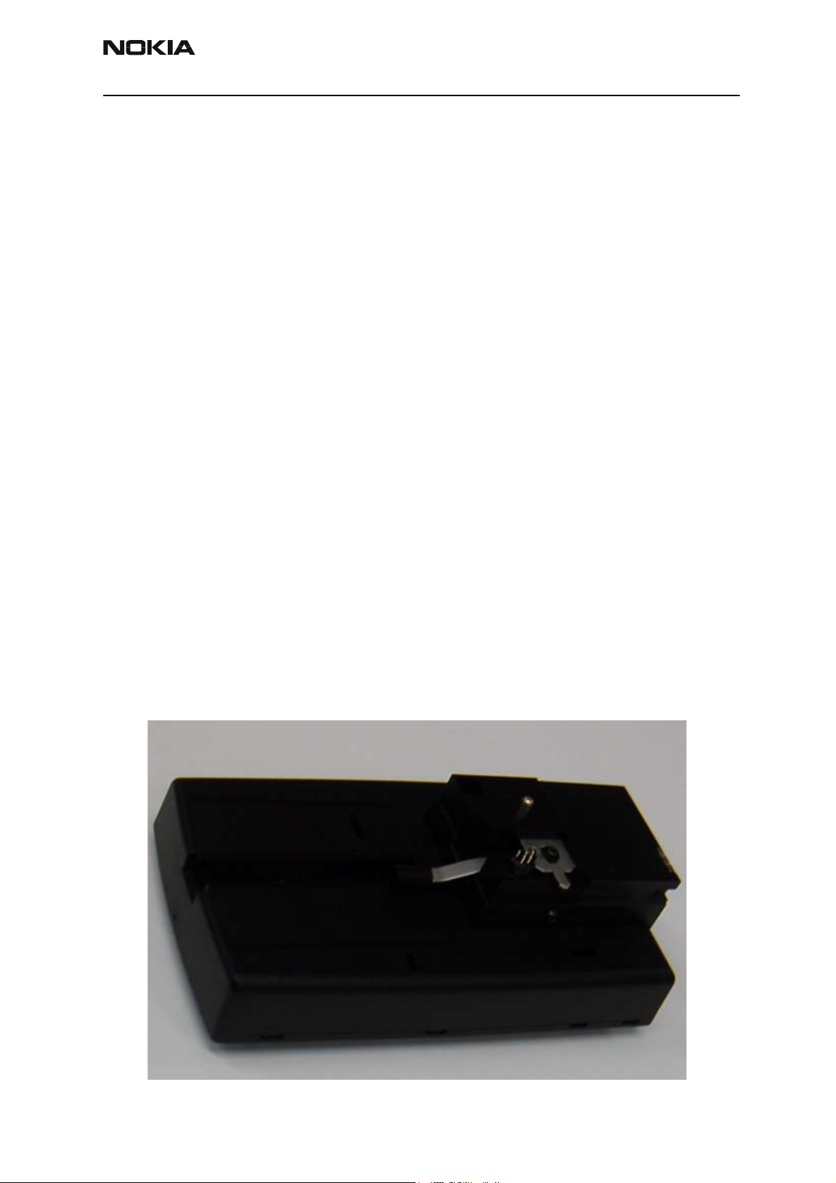
JBV-1 Docking Station and MJF-26 Adapter
The JBV-1 Docking Station has been designed for calibration and software update use.
The MJF-26 Docking Station Adapter makes signal connections to the phone. JBV-1 and
MJF-26 are used as one unit.
JBV-1 main electric functions are:
• adjustable VBATT calibration voltage, current measurement limit voltage
”VCHAR”, current measurement calibration current ”ICHAR”
• adjustable ADC calibration voltage via BTEMP and BSI signal
• BTEMP and BSI calibration resistor
• signals from FBUS to the phone via parallel jig
• control via FBUS or USB
• Flash OK/FAIL indication
In calibration mode JBV-1 is powered by external power supply 11-16V DC. In flashing
power for the phone can be taken from FPS-8 or external power supply 11-16V DC.
Product code
JBV-1 Docking Station: 0770298
MJF-26 Docking Station Adapter: 0770567
View of MJF-26
Figure 1: MJF-26
Issue 2 09/2004 Copyright © 2004 Nokia Corporation Page 4-3
Company Confidential
Page 4
NEM-4 Company Confidential
4 - Service Tools CCS Technical Documentation
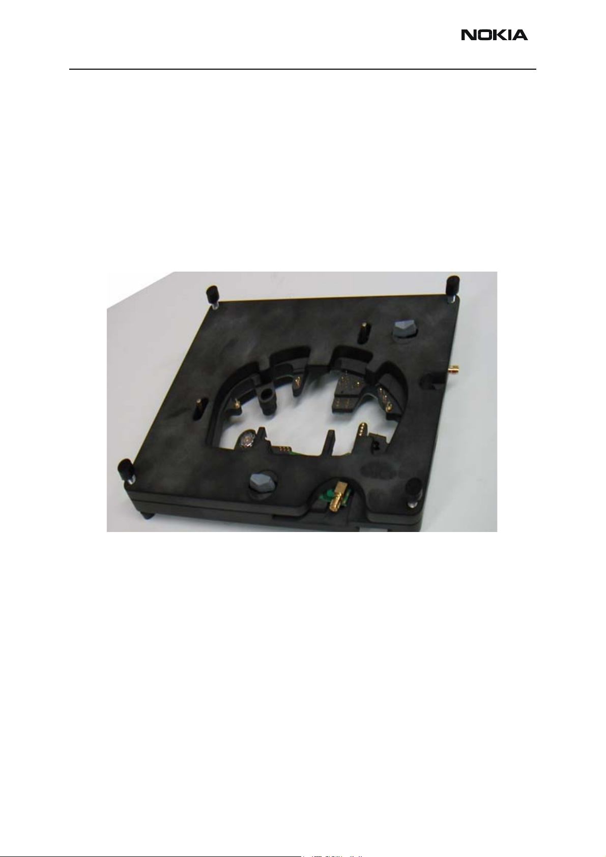
MJS-80 Module Jig
The MJS-80 Module Jig is used for testing of the following modules:
• User Interface
• Baseband and RF on system module
Product code
MJS-80 Module Jig: 0770566
View of MJS-80
Figure 2: MJS-80
*Note: The nominal supply voltage for MJS-80 is +6.0 V.
The supply voltage must not exceed +12.0 V (min 5V).
(MJS-80 has overvoltage protection.)
For flashing with FPS-8 it is possible to bypass regulator (jumper).
Page 4-4 Copyright © 2004 Nokia Corporation Issue 2 09/2004
Company Confidential
Page 5
Company Confidential NEM-4
CCS Technical Documentation 4 - Service Tools
RJ-10 Soldering Jig
The Soldering Jig RJ-10 is used for soldering and as a rework jig for system module.
Product code
RJ-10 Module Jig: 0770542
View of RJ-10
Figure 3: RJ-10
Issue 2 09/2004 Copyright © 2004 Nokia Corporation Page 4-5
Company Confidential
Page 6
NEM-4 Company Confidential
4 - Service Tools CCS Technical Documentation
LRK-2 / 3 LGA Component Rework Kits 1 & 2
Type designator Description Part code
LRK-2 (0273645) Kit 1
MJS-76 LGA Re-work Jig 0770417
SES-2 Stencil 0770415
SPS-2 Spreader 0770471
LRK-3 (0273646) Kit 2
SES-2 Stencil 0770415
SPS-2 Spreader 0770471
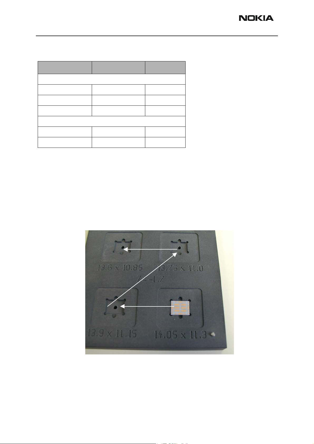
Rework procedure
Due to the large mechanical tolerance of the power amplifiers the following procedure is
necessary:
1 Put power amplifier into the MJS-76 re-work jig, the PA should be placed in the
best fit location, this is determined by firstly placing it in the largest location if
this is to large re-position the pa in the next size location, this should be carried
out until the best fit location is found.
34
1
2
Page 4-6 Copyright © 2004 Nokia Corporation Issue 2 09/2004
Company Confidential
Page 7

Company Confidential NEM-4
CCS Technical Documentation 4 - Service Tools
2 Once the best fit location has been found, leave the PA there and put stencil on
top of the jig and PA.
3 Put soldering paste on the PA properly.
4 Remove stencil and the PA from the jig.
5 Start soldering process.
Issue 2 09/2004 Copyright © 2004 Nokia Corporation Page 4-7
Company Confidential
Page 8

NEM-4 Company Confidential
4 - Service Tools CCS Technical Documentation
MJS-76 PA LGA Re-work Jig (Product Code 0770417)
Introduction
This tool is used in LGA type component reworking purposes in central service centers,
Part list
Part
number
1 Frame SME5S910 1
2 Cylindrical pin 3x12 640b003 1
3 Cylindrical pin 2x12 640B012 1
4 Type label 9380601 1
Name of Part
Material
code
Drawing number Qty
Exploded view
Page 4-8 Copyright © 2004 Nokia Corporation Issue 2 09/2004
Company Confidential
Page 9

Company Confidential NEM-4
CCS Technical Documentation 4 - Service Tools
FPS-8 Flash Prommer (Sales Pack)
The Flash Prommer FPS-8 is used with e.g. FLA-21 and JBV-1. Power is supplied to FPS-8
from the Universal Power Supply.
The sales pack includes:
• FPS-8 Flash Prommer 0750123
• FPS-8 Activation Sheet 9359289
• Universal Power Supply 0680032
• AXS-4 Service Cable (D9-D9) 0730090
• Printer cable 0730298
Sales package code
FPS-8 Flash Prommer: 0080321
View of FPS-8
Figure 4: FPS-8
Issue 2 09/2004 Copyright © 2004 Nokia Corporation Page 4-9
Company Confidential
Page 10

NEM-4 Company Confidential
4 - Service Tools CCS Technical Documentation
FPS-8C Parallel Flash Prommer (Sales Pack)
The Parallel Flash Prommer FPS-8C is used with MJF-6 and JBV-1. Flash programming
can be done to maximum of 8 phones parallel. FPS-8C consists of eight SF11C programming cards. SF11C card is functionally identical to FPS-8.
Sales package code
FPS-8C Parallel Flash Prommer: 0080396
View of FPS-8C
Figure 5: FPS-8C
ACF-8 Universal Power Supply
ACF-8 Universal Power Supply is used to power FPS-8. ACF-8 has 6 V DC and 2.1 A output.
Product code
ACF-8 Universal Power Supply: 0680032
View of ACF-8
Figure 6:
Picture will be added here later.
Page 4-10 Copyright © 2004 Nokia Corporation Issue 2 09/2004
Company Confidential
Page 11

Company Confidential NEM-4
CCS Technical Documentation 4 - Service Tools
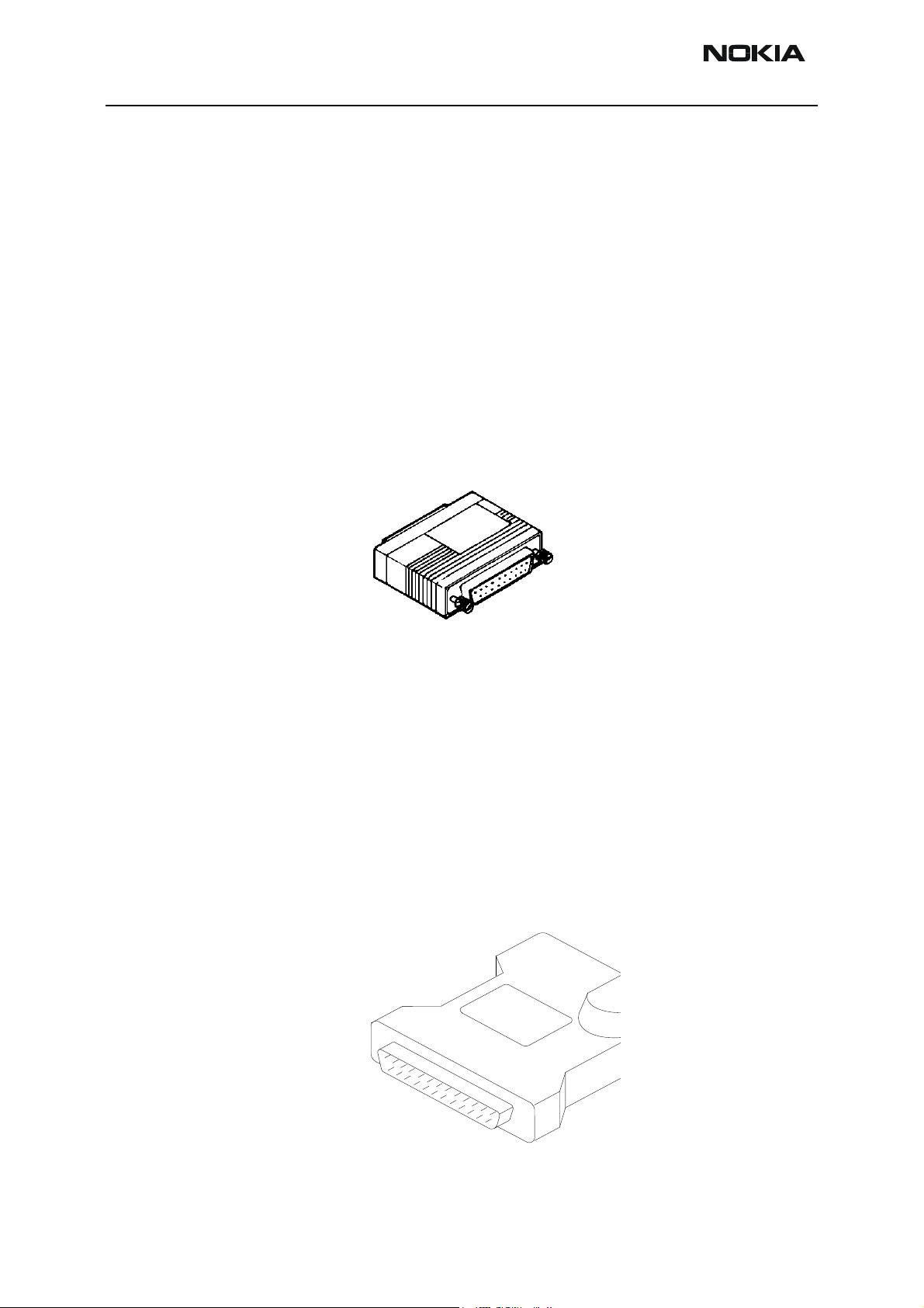
FLA-41 POS (Point Of Sale) Flash Loading Adapter
The POS Flash Loading Adapter FLA-41 is used in place of the phone’s normal battery
during service, to supply a controlled operating voltage and to connect to pads which are
under battery.
Product code
FLA-41 POS Flash Loading Adapter: 0770565
View of FLA-41
Figure 7: FLA-41
Issue 2 09/2004 Copyright © 2004 Nokia Corporation Page 4-11
Company Confidential
Page 12
NEM-4 Company Confidential
4 - Service Tools CCS Technical Documentation
FLC-2 DC Cable
The FLC-2 is used to supply a controlled operating voltage to FLA-41 adapter.
Product code
FLC-2 DC Cable: 0730185
View of FLC-2
Figure 8: FLC-2
Page 4-12 Copyright © 2004 Nokia Corporation Issue 2 09/2004
Company Confidential
Page 13

Company Confidential NEM-4
CCS Technical Documentation 4 - Service Tools
AXS-4 Service Cable
The AXS-4 D9-D9 Service Cable is used to connect two 9 pin D connectors e.g. between
PC and FPS-8. Cable length is 2 meters.
Product code
AXS-4 D9-D9 Service Cable: 0730090
View of AXS-4
Figure 9: AXS-4
XCS-1 Service Cable
The XCS-1 Service Cable is used to connect FLS-4S to FLA-41.
Product code
XCS-1 Service Cable: 0730218
View of XCS-1
Figure 10: XCS-1
Issue 2 09/2004 Copyright © 2004 Nokia Corporation Page 4-13
Company Confidential
Page 14
NEM-4 Company Confidential
4 - Service Tools CCS Technical Documentation
SW Security Device PKD-1
SW security device is a piece of hardware enabling the use of the service software when
connected to the parallel (LPT) port of the PC. Whithout the dongle present it is not possible to use the service software. Printer or any such device can be connected to the PC
through the dongle if needed.
Caution: Make sure that you have switched off the PC and the printer before making connections!
Caution: Do not connected the PKD-1 to the serial port. Product Code
SW Security Device PKD-1: 0750018
View of SW Security Device
Figure 11: PKD-1
FPS-4S POS (Point Of Sale) Flash Device (Sales Pack)
FLS–4S is a dongle and flash device incorporated into one package, developed specifically for POS use.
Product code
FPS-4S Sales Pack – Europe/Africa 0080541
FPS-4S Sales Pack – APAC 0080542
FPS-4S Sales Pack – Americas 0080543
View of FPS-4S
Figure 12: FPS-4S
Page 4-14 Copyright © 2004 Nokia Corporation Issue 2 09/2004
Company Confidential
Page 15

Company Confidential NEM-4
CCS Technical Documentation 4 - Service Tools
PCS-1 Power Cable
The PCS-1 Power Cable (DC) is used to connect e.g. JBV-1 or MJS-80 to FPS-8.
Product code
PCS-1 Power Cable: 0730012
View of PCS-1
Figure 13: PCS-1
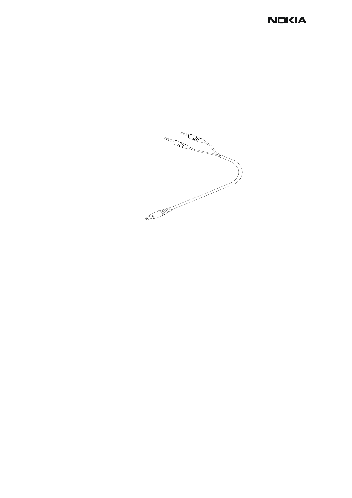
XRF-1 RF Cable
RF cable XRF-1 is used to connect e.g. MJS-80, CPL-5, TDS-10 or RA7 to RF measurement equipment. XRS-6 RF Cable can also be used.
Product code
XRF-1 RF Cable: 0730085
XRS-6 RF Cable: 0730231
View of XRF-1
Figure 14: XRF-1
Issue 2 09/2004 Copyright © 2004 Nokia Corporation Page 4-15
Company Confidential
Page 16

NEM-4 Company Confidential
4 - Service Tools CCS Technical Documentation
XRS-4 RF Cable
The XRS-4 RF cable is used for tuning with the MJS-26.
Product code
XRS-4 RF Cable: 0730221
View of XRS-4
Figure 15: XRS-4
XRS-11 RF Cable
The XRS-11 RF Cable is used for tuning with the MJS-80.
Product code
XRS-11 RF Cable 0730265
View of XRS-11
Figure 16: XRS-11
Page 4-16 Copyright © 2004 Nokia Corporation Issue 2 09/2004
Company Confidential
Page 17

Company Confidential NEM-4
CCS Technical Documentation 4 - Service Tools
DAU-9S MBUS Cable
The MBUS Cable DAU-9S has a modular connector, and is used with between PC’s serial
port and e.g. MJS-80, FLA-41, or JBV-1
Product code
DAU-9S MBUS Cable: 0730108
View of DAU-9S
Figure 17: DAU-9S
CA-5S DC Cable
The DC Cable CA-5S is used to connect e.g. JBV-1 to the phone. SCB-3 DC Cable can also
be used.
Product code
CA-5S DC Cable: 0730283
SCB-3 DC Cable: 0730114
View of SCB-3
Figure 18: SCB-3
Issue 2 09/2004 Copyright © 2004 Nokia Corporation Page 4-17
Company Confidential
Page 18

NEM-4 Company Confidential
4 - Service Tools CCS Technical Documentation
XCS-4 Modular Cable
XCS-4 is a shielded cable (one specially shielded conductor) modular cable for flashing
and service purposes.
Product code
XCS-4 Modular Cable: 0730178
View of XCS-4
Figure 19: XCS-4
DA-10DS Printer Cable
This cable is used to connect the PC to FPS-8.
Product code
DA-10DS Printer Cable: 0730298
View of Printer Cable
Figure 20: DA-10DS
Page 4-18 Copyright © 2004 Nokia Corporation Issue 2 09/2004
Company Confidential
Page 19

Company Confidential NEM-4
CCS Technical Documentation 4 - Service Tools
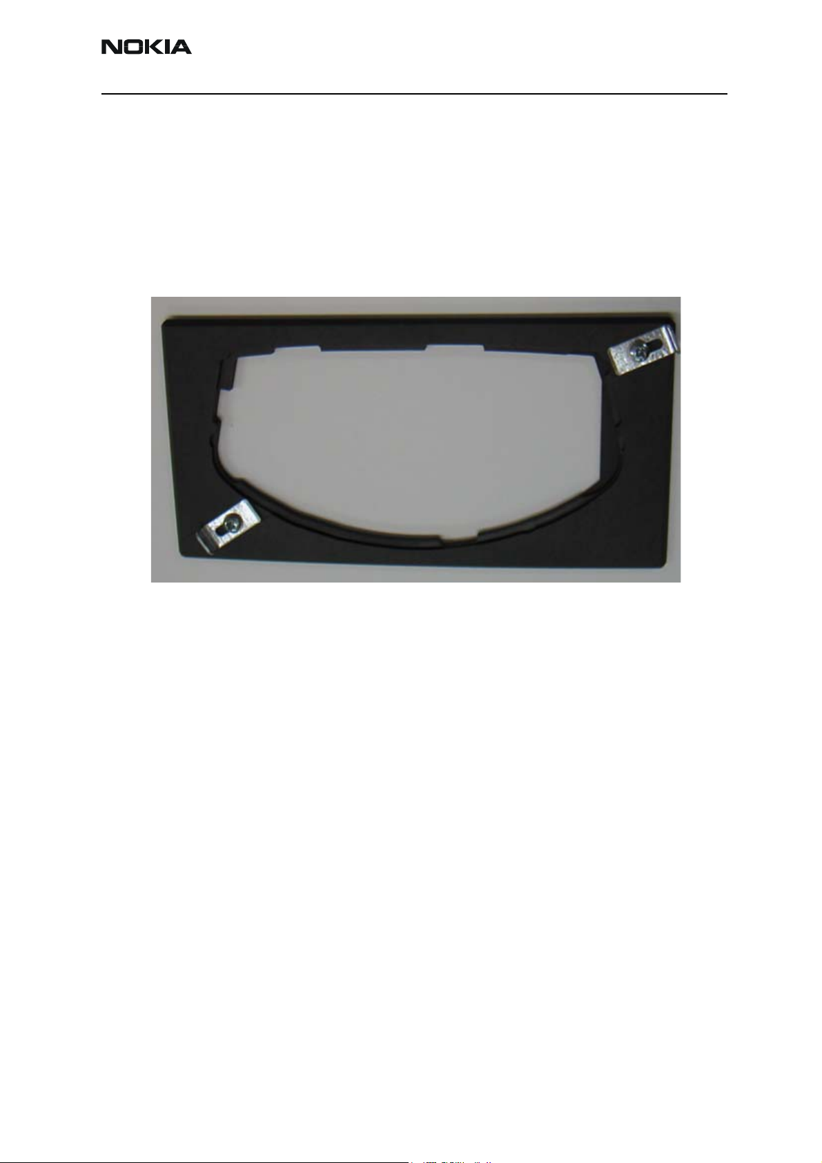
SS-17 Dome Sheet Assembly Jig
The SS-17 Dome Sheet Assembly Jig is used when new Dome Sheets need to be assembled.
Product code
SS-17 Dome Sheet Assembly Jig 0770773
View of SS-17
Figure 21: SS-17
Issue 2 09/2004 Copyright © 2004 Nokia Corporation Page 4-19
Company Confidential
Page 20

NEM-4 Company Confidential
4 - Service Tools CCS Technical Documentation
[This page left intentionally blank.]
Page 4-20 Copyright © 2004 Nokia Corporation Issue 2 09/2004
Company Confidential
 Loading...