

Page 1

NSP
Network Services Platform
Network Functions Manager - Packet (NFM-P)
Release 20.9
Installation and Upgrade Guide
3HE-16029-AAAC-TQZZA
Issue 1
September 2020
Page 2

Legal notice
Nokia is a registered trademark of Nokia Corporation. Other products and company names mentioned herein may be trademarks or
tradenames of their respective owners.
The information presented is subject to change without notice. No responsibility is assumed for inaccuracies contained herein.
© 2020 Nokia.
NFM-P
Release 20.9
September 2020
2 Issue 1
3HE-16029-AAAC-TQZZA
Page 3

Contents
NFM-P
Contents
About this document............................................................................................................................................8
Part I: Getting started...........................................................................................................................................9
1 Before you begin ..........................................................................................................................................11
1.1 Overview ...........................................................................................................................................11
General deployment information................................................................................................................12
1.2 Introduction .......................................................................................................................................12
1.3 To obtain the UUID of a station .........................................................................................................14
1.4 Using hostnames in the management network .................................................................................15
1.5 Deployment in a VM..........................................................................................................................18
1.6 GUI client deployment.......................................................................................................................20
NFM-P deployment requirements and restrictions...................................................................................23
1.7 NFM-P deployment requirements .....................................................................................................23
1.8 NFM-P deployment restrictions.........................................................................................................26
2 Using samconfig ..........................................................................................................................................31
2.1 Overview ...........................................................................................................................................31
2.2 Introduction .......................................................................................................................................31
2.3 Usage instructions.............................................................................................................................34
3 RHEL OS configuration ...............................................................................................................................39
3.1 Overview ...........................................................................................................................................39
RHEL OS deployment restrictions and requirements ..............................................................................40
3.2 Introduction .......................................................................................................................................40
3.3 RHEL OS deployment restrictions.....................................................................................................40
3.4 RHEL OS deployment requirements.................................................................................................41
3.5 To prepare disk partitions for NFM-P installation...............................................................................43
3.6 To reset the disk partition reserved block counts ..............................................................................44
RHEL OS deployment in a VM ....................................................................................................................46
3.7 Introduction .......................................................................................................................................46
3.8 To deploy the RHEL OS for NFM-P using a qcow2 image ................................................................46
Manual RHEL OS installation......................................................................................................................52
3.9 Manual RHEL OS installation requirements......................................................................................52
3.10 Required RHEL environment and OS packages...............................................................................53
3.11 Required additional OS packages, auxiliary database......................................................................65
Release 20.9
September 2020
Issue 1 33HE-16029-AAAC-TQZZA
Page 4

Contents
NFM-P
4 RHEL disk configuration .............................................................................................................................67
4.1 Overview ...........................................................................................................................................67
4.2 Introduction .......................................................................................................................................67
4.3 Sizing the NE configuration backup partition ....................................................................................68
4.4 To configure and mount NFM-P disk partitions .................................................................................69
4.5 Disk partitioning for trial deployments ...............................................................................................71
4.6 Disk partitioning for live deployments................................................................................................78
5 TLS configuration and management..........................................................................................................85
5.1 Overview ...........................................................................................................................................85
Introduction ..................................................................................................................................................86
5.2 About TLS .........................................................................................................................................86
5.3 NFM-P TLS implementation..............................................................................................................86
5.4 TLS deployment methods .................................................................................................................88
5.5 TLS certificate management .............................................................................................................91
5.6 Managing TLS versions and ciphers.................................................................................................94
Automated TLS deployment procedures...................................................................................................95
5.7 Workflow for automated TLS deployment .........................................................................................95
5.8 To configure and enable an NSP PKI server.....................................................................................96
5.9 To configure an NFM-P main server to request a PKI-server TLS certificate..................................100
5.10 To configure an NFM-P auxiliary server to request a PKI-server TLS certificate ............................103
Manual TLS deployment procedures .......................................................................................................107
5.11 Workflow for manual TLS deployment ............................................................................................107
5.12 To perform the TLS preconfiguration...............................................................................................108
5.13 To manually configure TLS on a main server ..................................................................................113
5.14 To manually configure TLS on an auxiliary server...........................................................................117
General TLS configuration procedures ...................................................................................................120
5.15 To disable TLS for XML API clients .................................................................................................120
5.16 To enable TLS for XML API clients ..................................................................................................122
5.17 To suppress security warnings in NFM-P browser sessions ...........................................................125
Part II: NFM-P system deployment..................................................................................................................127
6 NFM-P installation......................................................................................................................................129
6.1 Overview .........................................................................................................................................129
Introduction ................................................................................................................................................130
6.2 General information.........................................................................................................................130
Release 20.9
September 2020
4 Issue 1
3HE-16029-AAAC-TQZZA
Page 5

Contents
Standalone NFM-P system installation ....................................................................................................132
6.3 Standalone system installation workflow.........................................................................................132
6.4 To install a standalone NFM-P system............................................................................................133
Redundant NFM-P system installation.....................................................................................................158
6.5 Redundant system installation workflow .........................................................................................158
6.6 To install a redundant NFM-P system .............................................................................................159
Auxiliary server installation ......................................................................................................................213
6.7 Auxiliary server installation workflow...............................................................................................213
6.8 To install an NFM-P auxiliary server................................................................................................214
6.9 To add auxiliary servers to an NFM-P system.................................................................................220
Auxiliary database installation .................................................................................................................227
6.10 Auxiliary database installation overview..........................................................................................227
6.11 Auxiliary database installation workflow..........................................................................................227
6.12 To prepare a station for auxiliary database installation ...................................................................229
6.13 To install the NFM-P auxiliary database software ...........................................................................232
6.14 To add an auxiliary database to an NFM-P system.........................................................................235
6.15 To add a station to an NFM-P auxiliary database............................................................................239
6.16 To convert a standalone auxiliary database to geo-redundancy .....................................................250
NFM-P
7 NFM-P qcow deployment ..........................................................................................................................253
7.1 Introduction .....................................................................................................................................253
7.2 To deploy a collocated standalone NFM-P system using a qcow disk image .................................253
8 NFM-P upgrade...........................................................................................................................................261
8.1 Overview .........................................................................................................................................261
Introduction ................................................................................................................................................262
8.2 Overview .........................................................................................................................................262
8.3 General NFM-P system upgrade workflow......................................................................................263
8.4 To perform the pre-upgrade tasks ...................................................................................................264
8.5 To apply an NSP RHEL qcow2 OS update .....................................................................................278
Standalone NFM-P system upgrade.........................................................................................................281
8.6 Standalone system upgrade workflow ............................................................................................281
8.7 To upgrade a standalone NFM-P system........................................................................................283
Redundant NFM-P system upgrade .........................................................................................................304
8.8 Component references....................................................................................................................304
8.9 Redundant system upgrade workflow .............................................................................................305
8.10 To upgrade a redundant NFM-P system .........................................................................................310
Release 20.9
September 2020
Issue 1 53HE-16029-AAAC-TQZZA
Page 6

Contents
NFM-P
Auxiliary server upgrade ...........................................................................................................................348
8.11 To upgrade an NFM-P auxiliary server............................................................................................348
NSP Release 18 Flow Collector upgrade .................................................................................................351
8.12 To upgrade a Release 18 NSP Flow Collector................................................................................351
Auxiliary database upgrade ......................................................................................................................354
8.13 To upgrade an NFM-P auxiliary database.......................................................................................354
NFM-P analytics server upgrade ..............................................................................................................364
8.14 To upgrade the NFM-P analytics servers ........................................................................................364
9 NFM-P conversion to redundancy............................................................................................................381
9.1 Overview .........................................................................................................................................381
Introduction ................................................................................................................................................382
9.2 General information.........................................................................................................................382
9.3 System conversion to redundancy workflow ...................................................................................383
NFM-P system conversion to redundancy ..............................................................................................385
9.4 To convert a standalone NFM-P system to a redundant system.....................................................385
10 NFM-P conversion to IPv6 .........................................................................................................................421
10.1 Overview .........................................................................................................................................421
Introduction ................................................................................................................................................422
10.2 General information.........................................................................................................................422
10.3 System conversion to IPv6 workflow...............................................................................................423
10.4 To perform the pre-conversion tasks...............................................................................................423
NFM-P system conversion to IPv6 ...........................................................................................................428
10.5 To convert a standalone NFM-P system to IPv6 .............................................................................428
10.6 To convert a redundant NFM-P system to IPv6...............................................................................440
11 NFM-P uninstallation .................................................................................................................................471
11.1 Overview .........................................................................................................................................471
11.2 Introduction .....................................................................................................................................471
11.3 NFM-P system uninstallation workflow............................................................................................472
11.4 To uninstall an auxiliary server ........................................................................................................473
11.5 To uninstall an auxiliary database ...................................................................................................475
11.6 To uninstall a collocated main server and database .......................................................................476
11.7 To uninstall a distributed main server or main database .................................................................479
Part III: NFM-P client deployment....................................................................................................................483
12 Single-user client deployment ..................................................................................................................485
12.1 Overview .........................................................................................................................................485
Release 20.9
September 2020
6 Issue 1
3HE-16029-AAAC-TQZZA
Page 7

Contents
Introduction ................................................................................................................................................486
12.2 Single-user GUI client deployment..................................................................................................486
12.3 To install the Oracle JRE on a RHEL station ...................................................................................488
12.4 To configure a GUI client login form to list multiple NFM-P systems...............................................490
Single-user GUI client installation............................................................................................................492
12.5 To install an NFM-P single-user GUI client using the binary installer..............................................492
12.6 To install an NFM-P single-user GUI client using the JNLP installer ...............................................497
Single-user GUI client upgrade.................................................................................................................503
12.7 To upgrade an NFM-P single-user GUI client..................................................................................503
Single-user GUI client uninstallation........................................................................................................511
12.8 To uninstall a single-user GUI client installed using the binary installer ..........................................511
12.9 To uninstall a single-user GUI client installed using the JNLP installer...........................................512
13 Client delegate server deployment...........................................................................................................515
13.1 Overview .........................................................................................................................................515
Introduction ................................................................................................................................................516
13.2 Client delegate server deployment..................................................................................................516
Client delegate server installation............................................................................................................518
13.3 To add a client delegate server to an NFM-P system......................................................................518
13.4 To install an NFM-P client delegate server using the binary installer..............................................521
13.5 To install an NFM-P client delegate server using the JNLP installer ...............................................527
Client delegate server upgrade.................................................................................................................538
13.6 To upgrade an NFM-P client delegate server..................................................................................538
Client delegate server uninstallation .......................................................................................................544
13.7 To uninstall a client delegate server installed using the binary installer ..........................................544
13.8 To uninstall a client delegate server installed using the JNLP installer ...........................................545
NFM-P
Release 20.9
September 2020
Issue 1 73HE-16029-AAAC-TQZZA
Page 8

About this document
About this document
Purpose
The NSP NFM-P Installation and Upgrade Guide describes NFM-P installation, upgrade, and
platform modification operations such as system conversion to redundancy and system conversion
to IPv6.
Scope
The scope of this document is limited to the NFM-P application. Many configuration, monitoring,
and assurance functions that can be accomplished from the NFM-P Java GUI are also delivered in
NSP web-based applications accessible from the NSP Launchpad. Readers of this NFM-P guide
should familiarize themselves with the capabilities of the NSP applications, which often offer more
efficient and sophisticated features for network and service management. Help for all installed NSP
applications is available in the NSP Help Center.
Safety information
For your safety, this document contains safety statements. Safety statements are given at points
where risks of damage to personnel, equipment, and operation may exist. Failure to follow the
directions in a safety statement may result in serious consequences.
NFM-P
Document support
Customer documentation and product support URLs:
Documentation Center
•
• Technical support
How to comment
Documentation feedback
Release 20.9
September 2020
8 Issue 1
3HE-16029-AAAC-TQZZA
Page 9

Getting started
Part I: Getting started
Overview
Purpose
This part describes how to prepare for NFM-P system or system component deployment, and
includes important requirements, restrictions, and platform configuration procedures.
Contents
Chapter 1, Before you begin 11
Chapter 2, Using samconfig 31
Chapter 3, RHEL OS configuration 39
Chapter 4, RHEL disk configuration 67
NFM-P
Chapter 5, TLS configuration and management 85
Release 20.9
September 2020
Issue 1 93HE-16029-AAAC-TQZZA
Page 10

Getting started
NFM-P
Release 20.9
September 2020
10 Issue 1
3HE-16029-AAAC-TQZZA
Page 11

Before you begin
Overview
1 Before you begin
1.1 Overview
1.1.1 Purpose
This chapter describes the requirements and restrictions that apply to NFM-P system deployment,
and contains other important information that you must read and understand before you attempt to
deploy an NFM-P component.
1.1.2 Contents
1.1 Overview 11
General deployment information 12
1.2 Introduction 12
NFM-P
1.3 To obtain the UUID of a station 14
1.4 Using hostnames in the management network 15
1.5 Deployment in a VM 18
1.6 GUI client deployment 20
NFM-P deployment requirements and restrictions 23
1.7 NFM-P deployment requirements 23
1.8 NFM-P deployment restrictions 26
Release 20.9
September 2020
Issue 1 113HE-16029-AAAC-TQZZA
Page 12

Before you begin
General deployment information
Introduction
General deployment information
1.2 Introduction
1.2.1 Description
CAUTION
Service Disruption
An NFM-P system upgrade, conversion to redundancy, or conversion to IPv6 requires a thorough
understanding of NFM-P system administration and platform requirements, and is supported only
under the conditions described in this guide, the NSP NFM-P Planning Guide, and the NFM-P
Release Notice.
Such an operation must be planned, documented, and tested in advance on a trial system that is
representative of the target live network. Contact technical support to assess the requirements of
your NFM-P deployment, and for information about the upgrade service, which you are strongly
recommended to engage for any type of deployment.
NFM-P
This chapter describes the general conditions that apply to NFM-P deployment. Before you attempt
to deploy or configure an NFM-P component, you must comply with the conditions in this chapter
and ensure that the NFM-P platform is configured as described in the remaining chapters of
“Getting started”
Part III: “NFM-P client deployment” contains OS-specific information about single-user GUI client
and client delegate server deployment.
Guide conventions
This guide uses the following terminology:
• station—a discrete processing entity, such as a physical or virtual computer
• peer—an equivalent component in the same system. For example, the peer main server of the
primary main server in a redundant system is the standby main server. The term peer is
irrespective of the primary or standby role.
The procedures in this guide include default parameter values, when appropriate. A default value is
acceptable in most deployment environments, but must be validated against specific requirements,
for example, firewall constraints. For more information, see the NSP NFM-P Planning Guide and the
current NFM-P Release Notice, or contact technical support.
Platform support
You can deploy NFM-P components in a virtual machine, or VM. See the NSP NFM-P Planning
Guide for VM host system requirements, and
deployment requirements and restrictions.
.
1.5 “Deployment in a VM” (p. 18) for general
Part I:
An NFM-P system has the following required components:
• one standalone main server, or two in a redundant deployment
Release 20.9
September 2020
12 Issue 1
3HE-16029-AAAC-TQZZA
Page 13

Before you begin
General deployment information
Introduction
• one standalone main database, or two in a redundant deployment
• one or more single-user GUI clients or client delegate servers
An NFM-P deployment can include the following optional components:
• auxiliary servers
• an auxiliary database
An NFM-P system may interwork with the following, which are former NFM-P components:
• NSP Flow Collectors
• NSP analytics servers
Note: For NSP Flow Collectors, the NSP NFM-P Installation and Upgrade Guide describes
only an upgrade from Release 18.
The NSP Deployment and Installation Guide describes the following NSP Flow Collector
deployment operations:
• installation
• upgrade from Release 19 or later
• uninstallation
NFM-P
Note: The NSP NFM-P Installation and Upgrade Guide describes only the upgrade of an
NFM-P analytics server to an NSP analytics server.
The NSP Deployment and Installation Guide describes the following NSP analytics server
deployment operations:
• installation
• upgrade
• uninstallation
Note: CPAM functions in an NFM-P system are enabled only when the system includes one
or more operational 7701 CPAA devices. See the 7701 CPAA and vCPAA Setup and
Installation Guide for 7701 CPAA deployment information.
The following table lists the supported platforms for each NFM-P component type.
Table 1-1 NFM-P platform support by component
NFM-P component Mac OS X Microsoft Windows RHEL
Main server ✓
Main database ✓
Auxiliary server ✓
Auxiliary database ✓
Client delegate server ✓ ✓
Single-user client ✓ ✓ ✓
Release 20.9
September 2020
Issue 1 133HE-16029-AAAC-TQZZA
Page 14

Before you begin
General deployment information
To obtain the UUID of a station
nsp user account
NFM-P system operation and management require a RHEL user account called nsp in the nsp user
group.
• The initial installation of any of the following components on a station creates the group and
account:
− main server
− auxiliary server
• The nsp user owns all NFM-P server processes; only the nsp user can start or stop a server, or
run a server script.
• The nsp home directory is /opt/nsp.
• The initial nsp password is randomly generated, and must be changed by the root user.
• The root user owns some files in the /opt/nsp/nfmp/server directory for low-level installation and
support functions.
• Server uninstallation does not remove the nsp user account, user group, or home directory.
• Root user privileges are required only for component installation or upgrade, and for low-level
support functions.
NFM-P
1.2.2 Integration with other products or NSP components
For information about NFM-P integration with other products or NSP components, see the NSP
Deployment and Installation Guide.
1.3 To obtain the UUID of a station
1.3.1 Description
An NFM-P license is specific to the UUID of a main server station, and must be provided in a
license request. The following steps describe how to obtain the UUID of a station that is to host an
NFM-P main server.
Note: If you are using an Integrated Lights Out Management system, ensure that you obtain
the UUID of the intended blade and not the UUID of the ILO module.
Note: You must perform this procedure on each station that is to host a main server.
Note: A leading # character in a command line represents the root user prompt, and is not to
be included in a typed command.
1.3.2 Steps
1
Log in to the main server station as the root user.
Release 20.9
September 2020
14 Issue 1
3HE-16029-AAAC-TQZZA
Page 15
Before you begin
General deployment information
Using hostnames in the management network
2
Open a console window.
3
Enter the following:
# cat /sys/devices/virtual/dmi/id/product_uuid ↵
The UUID is displayed; for example:
35F59783-2258-11E1-BBDA-38B41F432C41
4
Record the value for use when you request the NFM-P license for the main server.
END OF STEPS
1.4 Using hostnames in the management network
NFM-P
1.4.1 Overview
The topology of an NFM-P management network may be sufficiently complex to benefit from or
require the use of hostnames, rather than fixed IP addresses, for communication between NFM-P
components. Hostname resolution is of even greater benefit when NAT is used between NFM-P
clients and a main server.
Also, some CA signing authorities include only hostnames, and not IP addresses, in the SAN field
of a signed TLS certificate.
Note: If the SAN field of a signed certificate includes only hostnames, when you use the
samconfig utility to configure client access on a main server, you must specify a hostname,
rather than an IP address.
Description
This section provides a configuration example for hostname resolution in a moderately complex
NFM-P management network that may or may not include a NAT configuration.
Note: When the NFM-P clients and the auxiliary or peer main servers use different main
server interfaces to communicate with a main server, the clients must use a hostname to
reach the main server. See the NSP NFM-P Planning Guide for more information.
Note: If a TLS certificate to be signed by a public CA includes a hostname, the hostname
must be an FQDN and not a short hostname. A self-signed certificate can use an FQDN or a
short hostname.
Release 20.9
September 2020
Issue 1 153HE-16029-AAAC-TQZZA
Page 16

Before you begin
General deployment information
Using hostnames in the management network
Note: Only local hostname resolution is supported. The use of a DNS server for NFM-P
hostname resolution is not supported.
To enable hostname resolution in an NFM-P management network, you must do the following:
• Configure the local /etc/hosts file on each component to ensure that each hostname translates to
the correct IP address; the hostname must:
− contain only ASCII alphanumeric and hyphen characters.
− not begin or end with a hyphen.
− not begin with a number.
− comply with the format defined in IETF RFC 1034.
− use period characters delimit the FQDN components.
− not exceed 63 characters.
• During component deployment, specify hostnames instead of IP addresses.
Note: Hostnames are case-sensitive.
Hostname usage requirements and restrictions
NFM-P
When two server components use hostnames to communicate, the /etc/hosts file must contain the
following:
• on a main server:
− an entry for each auxiliary server that maps the auxiliary server hostname to the IP address
of the auxiliary server interface that is used for main server communication
− an entry for each database that maps the database hostname to the IP address of the
database interface that is used for main server to database communication
• on an auxiliary server:
− an entry for each main server that maps the main server hostname to the IP address of the
main server interface that is used for auxiliary server communication
− an entry for each auxiliary server that maps the auxiliary server hostname to the IP address
of the auxiliary server interface that is used for main server communication
− an entry for each database that maps the database hostname to the IP address of the
database interface that is used for database communication
Note: Each main server must map an auxiliary server hostname to the same IP address.
Note: A component hostname that you specify in an /etc/hosts file must be the exact
hostname returned by the following command:
hostname
If the command returns localhost.localdomain, the hostname is not set; you must set the
hostname using the following command as the root user:
hostnamectl set-hostname
where hostname is the short hostname or FQDN, depending on your requirement
hostname
Note: Depending on the management network topology, the hosts files of various components
may map the same main server hostname to different IP addresses in order to reach the
correct main server interface.
Release 20.9
September 2020
16 Issue 1
3HE-16029-AAAC-TQZZA
Page 17

...2.1
192.168.1.1
Main server
main_a
NIC 1
NIC 3
192.168.4.1
...2.5
...2.3 ...2.4
Switch/
Router
Switch/
Router
Switch/
Router
NFM-P
clients
IPv6 Managed
Network
...2.6
Switch/
Router
Switch/
Router
Switch/
Router
2001:0DB8::0001
NIC 4
192.168.4.2
192.168.1.2
...2.2
NIC 2
25709
2001:0DB8::0002
Auxiliary
server aux_a
NIC 1
NIC 3
NIC 4
NIC 2
Main database
db_a
NIC 1
NIC 4
Main server
main_b
NIC 2
NIC 3
NIC 4
NIC 1
Auxiliary
server aux_b
NIC 2
NIC 3
NIC 4
NIC 1
Main database
db_b
NIC 1
NIC 4
IPv4 Managed
Network
Before you begin
General deployment information
Using hostnames in the management network
Note: Each main and auxiliary server must have a network route to each address provided in
a TLS certificate.
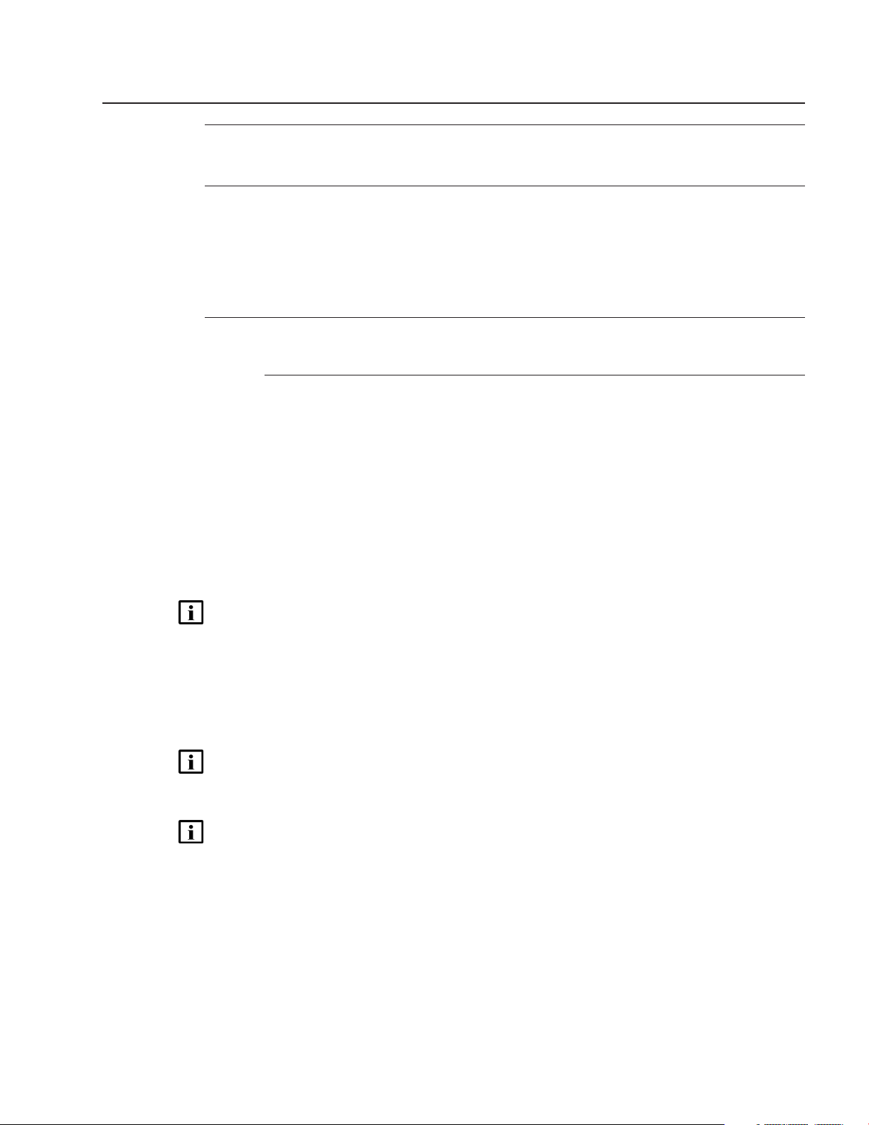
Management network configuration example
The following example provides guidance about configuring local hostname resolution for NFM-P
components in a relatively complex management network. In the example, each main server
communicates with multiple networks using separate interfaces, as shown in
“Management network topology” (p. 16)
Figure 1-1 Management network topology
NFM-P
Figure 1-1,
.
The client IP addresses are in the 192.168.1 subnet, and the internal management IP addresses
are in the 192.168.2 subnet.
The component hostnames in the example are the following:
Release 20.9
September 2020
Issue 1 173HE-16029-AAAC-TQZZA
Page 18

Before you begin
General deployment information
Deployment in a VM
• main servers—main_a and main_b
• main databases—db_a and db_b
• auxiliary servers—aux_a and aux_b
The same configuration methodology must be applied to all components in the internal
management network. The following are the configuration requirements for each component in the
192.168.2 subnet.
The /etc/hosts file on station main_a requires the following entries:
192.168.2.1 main_a
192.168.2.2 main_b
192.168.2.5 aux_a
192.168.2.6 aux_b
192.168.2.3 db_a
192.168.2.4 db_b
127.0.0.1 localhost
NFM-P
The /etc/hosts file on station aux_a requires the following entries:
192.168.2.5 aux_a
192.168.2.6 aux_b
192.168.2.1 main_a
192.168.2.2 main_b
192.168.2.3 db_a
192.168.2.4 db_b
127.0.0.1 localhost
The /etc/hosts file on station db_a requires the following entries:
192.168.2.3 db_a
192.168.2.4 db_b
127.0.0.1 localhost
1.5 Deployment in a VM
1.5.1 Description
The requirements and restrictions below apply to NFM-P component deployment in a virtual
machine, or VM. VM deployment is supported in the following environments:
• KVM
• Openstack
• VMware
Release 20.9
September 2020
18 Issue 1
3HE-16029-AAAC-TQZZA
Page 19

Before you begin
General deployment information
Deployment in a VM
Note: The requirements and restrictions in “NFM-P deployment requirements and
restrictions” (p. 23)
Note: Before you deploy an NFM-P component in a VMware VM, you must install the latest
VMware Tools software.
See the NSP NFM-P Planning Guide for the hardware virtualization requirements, and for the
specific configuration requirements of a supported environment.
also apply to VM deployments.
1.5.2 VM deployment using qcow images
You can use qcow2 disk images to deploy the following:
• RHEL OS, for subsequent component installation; see
• NFM-P system; see Chapter 7, “ NFM-P qcow deployment”
1.5.3 NFM-P server and database virtualization
The following conditions apply to main server, auxiliary server, client delegate server, or database
deployments in VMs.
• The guest OS must be an NFM-P-supported version of RHEL 7 Server x86-64.
• A RHEL deployment on VMware requires VMXNET 3 NIC adapters; see the VMware
documentation for information.
NFM-P
“RHEL OS deployment in a VM” (p. 46)
1.5.4 Client virtualization
The following conditions apply to NFM-P single-user GUI client deployment in a VM.
• You can deploy a VM client in a live network environment only if the client resources are
dedicated to the guest OS, and not shared or oversubscribed.
• The guest OS must be a supported OS version; see the NSP NFM-P Planning Guide.
• The supported connection application for a VMware ESXi Windows platform is Windows Remote
Desktop.
Additional EMS requirements and restrictions
The following conditions apply to an NFM-P single-user GUI client or client delegate server in a VM
that requires the installation of an additional element manager on the same platform, or is to use an
additional NE management interface.
• You can use two or more NICs to isolate network traffic between the client VM and the managed
NEs. Such a configuration may be required when an additional element manager, for example,
NEtO, must share the client resources, or when web-based NE management is to be performed
from the client station.
• Additional RAM, disk space, and CPU resources are required to accommodate an element
manager that shares a client platform; see the NSP NFM-P Planning Guide.
Release 20.9
September 2020
Issue 1 193HE-16029-AAAC-TQZZA
Page 20

Before you begin
General deployment information
GUI client deployment
1.6 GUI client deployment
1.6.1 Single-user GUI client and client delegate server deployment
The following NFM-P GUI client deployment scenarios are supported:
• separate single-user client installations
• remote user connections to a common client instance on a client delegate server
You can install multiple single-user GUI clients on one station, or on separate stations. The multiple
clients installed on one station can be at various releases and associated with the different NFM-P
systems.
You can also configure one single-user client to connect to multiple NFM-P systems. For
information , see
(p. 490)
A client delegate server allows NFM-P access to multiple remote clients using one client software
instance. If multiple client delegate servers are required, they are deployed on separate stations.
The installation or upgrade of an NFM-P single-user GUI client or client delegate server is a
software push from a main server that you initiate using a browser on the client or client delegate
server station. The main server must be installed and fully initialized before you can install or
upgrade the client software.
.
12.4 “To configure a GUI client login form to list multiple NFM-P systems”
NFM-P
The software push mechanism enables centralized client software management. During startup, an
existing single-user client or client delegate server checks for available software updates on the
main server. Any available client configuration updates are also automatically applied.
See the following for client installation and upgrade information:
•
Chapter 12, “Single-user client deployment” —single-user client deployment
•
Chapter 13, “Client delegate server deployment” —client delegate server deployment
1.6.2 Client delegate servers
A client delegate server supports multiple simultaneous GUI sessions using one client software
installation. A client delegate server can host local and remote user sessions, and supports the use
of a third-party remote access tool such as a Citrix gateway. Client delegate server deployment is
supported on multiple platforms.
A GUI session that is opened through a client delegate server is functionally identical to a singleuser client GUI session. The client delegate server locally stores the files that are unique to each
user session, such as the client logs and GUI preference files, using a directory structure that
includes the RHEL or Windows username.
Figure 1-2, “Client delegate servers” (p. 21) shows two client delegate servers in an NFM-P
management network. Multiple local users log in to a client delegate server directly, and remote
users log in through a client delegate server that hosts a third-party access tool, for example, a
Citrix gateway. Another local user opens a session on a single-user client station.
Release 20.9
September 2020
20 Issue 1
3HE-16029-AAAC-TQZZA
Page 21

20165
Remote GUI users
Client delegate
server and
third-party access
server
Local GUI
users
Single-user
GUI client
Client delegate
server
main server and
database
Managed
network
Before you begin
General deployment information
GUI client deployment
Figure 1-2 Client delegate servers
NFM-P
If a client delegate server becomes unreachable, the NFM-P raises an alarm and changes the color
of the associated session entries in the GUI. The alarm clears when the server is again reachable.
You can use the client software on a client delegate server from the local console. It is
recommended that you install a client delegate server, rather than a single-user client, to facilitate
the deployment of additional clients.
A main server monitors the registered client delegate servers and displays information about them
in the GUI. To register a client delegate server, you specify the client delegate server IP address
and installation location during main server installation, upgrade, or configuration.
You can use a client GUI to list the following:
• registered client delegate servers and the availability of each
Release 20.9
September 2020
Issue 1 213HE-16029-AAAC-TQZZA
Page 22

Before you begin
General deployment information
GUI client deployment
• active client delegate server sessions
• active client sessions on a specific client delegate server
• active client sessions for a specific NFM-P user
The number of allowed NFM-P client sessions on a client delegate server is configurable as a
threshold using the client GUI. If a user tries to open a client session that reaches or exceeds the
threshold, the session proceeds and the client delegate server raises an alarm. This thresholdcrossing function can help to balance the session load across multiple client delegate servers. You
require the Update user permission on the Server package to configure the threshold.
The following restrictions apply to client delegate servers.
• The installation of only one client delegate server on a station is supported.
• You cannot change a single-user client to a client delegate server.
• A client delegate server connects to one release of main server; multiple main servers to which
the client delegate server connects must be at the same release.
• Depending on the platform type, specific deployment requirements and restrictions may apply;
see the NSP NFM-P Installation and Upgrade Guide for information.
NFM-P
1.6.3 Software upgrades
After an NFM-P main server upgrade, a single-user GUI client or client delegate server that
connects to the main server automatically detects the release mismatch and attempts an upgrade
to the main server release level.
During a software upgrade, an NFM-P client downloads and installs only the files required for the
upgrade. The upgrade process removes previously downloaded local files that are not required by
the updated client software.
1.6.4 Configuration updates
When the single-user GUI clients or client delegate servers that connect to a main server require a
configuration update, an administrator updates the global client configuration stored on a main
server. Each client instance detects and applies the update at the start of the next client session.
See “System component configuration procedures” in the NSP NFM-P Administrator Guide for
information about globally updating client configurations.
Note: A client backs up the existing configuration files as part of a configuration update.
Release 20.9
September 2020
22 Issue 1
3HE-16029-AAAC-TQZZA
Page 23

Before you begin
NFM-P deployment requirements and restrictions
NFM-P deployment requirements
NFM-P deployment requirements and restrictions
1.7 NFM-P deployment requirements
1.7.1 Network requirements
CAUTION
Service Disruption
The use of hostname resolution for GUI and XML API client communication with an NFM-P main
server in a NAT environment is strongly recommended.
When IP addresses are used in a NAT environment, the following conditions apply:
• All client communication with the main server must use the public IP address of the main server.
• The NAT firewall must be configured to allow the main server to communicate with itself using
the public IP address.
NFM-P
CAUTION
Service Disruption
In a redundant system, a GUI client that opens a browser connection to the primary NFM-P main
server may need to use the IP address or hostname of the peer main server after a main server
communication failure.
To resolve the two IP addresses or hostnames, a GUI client can use a common DNS name which
maps each main server IP address provided by the DNS server to the primary main server.
• Configure a DNS server for GUI clients to map each main server IP address to a common DNS
name.
• Configure each GUI client to use the common DNS name for browser connections to the NFM-P.
• Use a client browser that caches multiple IP addresses associated with one hostname.
The NFM-P network requirements apply to the following:
• management network—the network in which the NFM-P components communicate with each
other
• managed network and external systems—the managed NEs, and external management systems
that are integrated with the NFM-P
Management network
The following requirements apply to the NFM-P management network.
• During a main server installation or upgrade, you must use hostnames to identify the main server
interfaces under the following conditions:
− when the XML API and GUI clients communicate with a main server using multiple IP
addresses for the main server
Release 20.9
September 2020
Issue 1 233HE-16029-AAAC-TQZZA
Page 24

Before you begin
NFM-P deployment requirements and restrictions
NFM-P deployment requirements
− when the XML API and GUI clients use different addresses to communicate with a main
server through one interface on the main server
• A standalone auxiliary server must be accessible to each main server and database in a
redundant NFM-P system. Optimally, all components in a deployment are in the same LAN and
have high-quality network interconnection.
• Each station in an auxiliary database cluster must be on the same side of the management LAN,
and not geographically dispersed.
• The internal communication among the stations in an auxiliary database cluster must be isolated
to a dedicated private network. Each station IP address used for internal communication must be
associated with an interface connected to the private network, and must be the only IP address
of the interface.
• When two components use hostnames to communicate, the /etc/hosts file on each component
station must contain the following:
− an entry that maps the hostname assigned to the interface on the other component to the IP
address used to reach the other component
− an entry that maps the hostname of the other component station to each IP address used to
reach the other component
• Specifying a TCP or UDP port other than the default during an installation or upgrade can affect
component communication through a firewall. Ensure that you record any changes to default
port numbers and make the ports available through the firewall.
NFM-P
Hostname usage in an NFM-P system has special configuration requirements. See
hostnames in the management network” (p. 15)
3.4.2 “Network-level OS configuration requirements” (p. 41) for specific configuration
and
information.
Managed network and external systems
for an example management network configuration,
1.4 “Using
CAUTION
Management Disruption
If an NFM-P system that is to be upgraded manages a device as a GNE, and the new NFM-P
release supports native management of the device, you must unmanage the device and delete it
from the main database before the upgrade.
After the upgrade, you can use the NFM-P to discover and manage the device natively, rather than
as a GNE.
Note: Before you upgrade an NFM-P system that manages 7705 SAR, 7705 SAR-Hm, or
VSR NEs using NGE, you must observe the following:
• 7705 SAR - Release 8.0 R3 and earlier support only NGE version 1; Release 8.0 R4 and
later support only NGE version 2.
• 7705 SAR-Hm and VSR - Release 15.0 R3 and earlier support only NGE version 1;
Release 15.0 R4 and later support only NGE version 2.
If you want to manage such devices after the NFM-P upgrade using NGE version 2, you must
do the following:
Release 20.9
September 2020
24 Issue 1
3HE-16029-AAAC-TQZZA
Page 25

Before you begin
NFM-P deployment requirements and restrictions
NFM-P deployment requirements
1. Upgrade each device to a release that supports NGE version 2.
2. Use the NFM-P to specify NGE version 2 for each device.
The following requirements apply to the network of NFM-P-managed devices, and to the external
systems with which the NFM-P is integrated.
• Before you upgrade an NFM-P system, you must confirm that the new NFM-P software release
supports the release of each managed NE. If this is not true, you must perform one of the
following before you attempt the upgrade, or service disruption may occur.
− Upgrade the NE to a release that the new NFM-P release supports.
− Use an NFM-P client to unmanage the device, remove the device from the managed network,
and remove the discovery rule element for the device.
• Before you upgrade an NFM-P system, you must ensure that the new NFM-P software is
compatible with the software release of each integrated external system. Contact technical
support for information about external system compatibility.
• An NFM-P system that manages LTE RAN devices has special disk partitioning requirements.
Chapter 4, “RHEL disk configuration” for information.
See
• An NFM-P system upgrade does not preserve 9500 MPR device software images. If you want to
retain the images, you must export the images to a remote file system before the upgrade, and
import the images to the NFM-P after the upgrade.
• Before the NFM-P can manage some LTE RAN devices, functions such as PM statistics
transfers and network snapshots require configuration.
NFM-P
1.7.2 Platform requirements
Note: For optimal storage performance on a supported Nokia AirFrame server, set the default
write cache policy for each created storage volume to Write Through. See the NokiaAirFrame
server documentation for information about verifying, configuring, and setting the write cache
policy for a volume.
The following are the NFM-P platform requirements.
• The platform must meet the minimum requirements described in the NSP NFM-P Planning
Guide.
• The OS release and patch level of all main server, main database, and optional component
stations in an NFM-P system must be identical unless NFM-P OS support restrictions exist.
• The platform must be dedicated to the NFM-P only; sharing the platform is not supported.
System operation may be adversely affected by the activity of other software on the same
station.
• Before you install or upgrade a redundant NFM-P system, you must enable SSH on each main
server, auxiliary server, and main database station in the system.
• If the NFM-P is to collect statistics on a large scale, as defined in the NSP NFM-P Planning
Guide, you must use a disk array with the main database to increase performance. See
4, “RHEL disk configuration”
• The NFM-P XML API and GUI client real-time clocks must always be synchronized with the main
server real-time clock. The use of NTP or an equivalent time protocol is strongly recommended.
Chapter
for information.
Release 20.9
September 2020
Issue 1 253HE-16029-AAAC-TQZZA
Page 26

Before you begin
NFM-P deployment requirements and restrictions
NFM-P deployment restrictions
• The Bash shell is the supported command shell for RHEL CLI operations.
1.7.3 Security requirements
Note: The use of sudo to gain root user privileges is supported for NFM-P installation, and for
any other operation in this guide that requires root user privileges.
The following are the NFM-P security requirements.
• The Oracle management user requires full read and write permissions on the main database
installation directory, /opt/nsp/nfmp/db, and any specifically created partitions, for example, /opt/
nsp/nfmp/dbbackup.
• The user that installs an NFM-P single-user GUI nt requires local user privileges only, but must
have full access permissions on the client installation directory. The user that opens the client
installer must have sufficient file permissions to create the installation directory, or the installation
fails.
1.7.4 Software requirements
NFM-P
The following are the NFM-P software requirements.
• An NFM-P system deployment requires a license file in compressed format with a .zip extension.
A license file has the following characteristics.
− The UUID of the host station is required to generate the license.
station” (p. 14)
− The file can accommodate two system IDs, which enables the use of the same file on
redundant main servers, and is recommended.
− Renaming the compressed file has no effect on the validity of the contained license file, but
renaming the contained XML license file renders it invalid.
− The main server configuration utility copies the license file content to a backup location; a
change to the license file content or location after an installation or upgrade does not affect
the main server operation.
• You must ensure that you have sufficient time to complete a main database upgrade. The time
required for an upgrade depends on the platform resources, database complexity, and
tablespace configuration. See the NSP NFM-P Planning Guide for database upgrade time
estimates.
describes how to obtain a station UUID.
1.8 NFM-P deployment restrictions
1.8.1 Network restrictions
Note: The use of NAT between NFM-P server and database components is not supported.
The NFM-P supports NAT only between the following:
• main server and single-user client or client delegate server
• main or auxiliary server and XML API client
• main or auxiliary server and managed network
1.3 “To obtain the UUID of a
Release 20.9
September 2020
26 Issue 1
3HE-16029-AAAC-TQZZA
Page 27

Before you begin
NFM-P deployment requirements and restrictions
NFM-P deployment restrictions
Note: Before you attempt to deploy an NFM-P system, or add a component to a system, you
must ensure that any firewalls between the components allow the required traffic to pass
between the components, or are disabled. The NSP NFM-P Planning Guide lists the open
ports required by each component, and provides information about using NFM-P templates to
create RHEL Firewalld rules.
Note: If you use SSH X forwarding to perform a procedure in this guide, the “su - oracle”
command fails. In such a scenario, you must log in directly as the Oracle management user to
perform the required actions.
The following restrictions apply to the network environment in which an NFM-P system or
component is deployed.
• DNS or NIS name resolution is not supported between NFM-P components, and a pre-existing
name service must not conflict with NFM-P address resolution. The restriction also applies to
XML API client communication with the NFM-P.
• You cannot use “localhost” or an alias IP address to identify a component.
• An NFM-P main server listens for GUI and XML API client communication on only one interface
unless you specify a hostname for the main server during an installation or upgrade.
• You cannot use a hostname to identify a main database station; NFM-P components can use
only an IP address to reach a database.
• All IP communication from an NFM-P auxiliary server to an NFM-P main server must originate
from one IP address, which is the auxiliary server address specified during the main server
configuration. A main server rejects communication from an auxiliary server if the auxiliary server
uses a source address other than the configured address.
• During a single-user client installation, you can specify a hostname instead of an IP address to
identify a main server. A client upgrade occurs automatically through a connection to a main
server named in the client configuration.
NFM-P
IPv4 and IPv6
• NFM-P components communicate with other NFM-P components and external entities using
IPv4 or IPv6 exclusively, with the following exceptions:
− You can configure an NFM-P system to concurrently manage IPv4 and IPv6 networks.
− An NFM-P GUI or browser-based application client can connect to the NFM-P using IPv4 or
IPv6, regardless of the protocol version in use between the NFM-P server and database
components.
Note: If the GUI or application clients are to connect to the NFM-P using IPv4 and IPv6, when
you use the samconfig utility to configure client access on a main server, you must specify a
hostname rather than an IP address.
• Before you can specify an IPv6 address for an NFM-P component, the IPv6 interface must be
plumbed and operational. See the OS documentation for information about enabling and
configuring an IPv6 interface.
• Before you attempt to perform a procedure in
Chapter 10, “NFM-P conversion to IPv6”, the
NFM-P system must be at the software release described in this guide; you cannot combine an
upgrade and a conversion to IPv6 in one operation.
Release 20.9
September 2020
Issue 1 273HE-16029-AAAC-TQZZA
Page 28

Before you begin
NFM-P deployment requirements and restrictions
NFM-P deployment restrictions
1.8.2 Platform restrictions
The following are the NFM-P platform restrictions.
• An NFM-P single-user client or client delegate server cannot be installed on the same station as
an NFM-P server or database.
• An NFM-P single-user client and client delegate server cannot be installed on the same station.
• An optional system component requires a dedicated station. The sharing of a station by optional
components is not supported; attempts to deploy multiple components on one station fail.
• If you plan to convert a standalone NFM-P system to a redundant system, and also plan to
upgrade the system, you must perform the upgrade before the conversion.
• An NFM-P system conversion from IPv4 to IPv6 is not supported during an upgrade or
conversion to redundancy.
1.8.3 Security restrictions
The following are the NFM-P security restrictions.
• The user that starts an NFM-P client must be the user that installs the client software, or another
user that has read, write, and execute privileges on the client files and directories.
• An NFM-P domain name defines the network-management domain to which an NFM-P
component belongs, and must be unique to a network. An NFM-P component can interact only
with other NFM-P components in the same NFM-P domain. During system installation, you must
specify the same domain name for each component in the system.
NFM-P
1.8.4 General software restrictions
The following are general NFM-P software deployment restrictions. See also the NFM-P Release
Notice, which contains important release-specific information, before you attempt an operation
described in this guide.
• You cannot share an existing Oracle installation with the NFM-P, and no other application can
use the NFM-P Oracle software.
• You can specify the installation directory for a single-user client or client delegate server, but not
for any other type of component.
• You can deploy a main server without specifying a license file. However, if you do not specify a
license file, you cannot start the main server until you import a license. See “Software and
license configuration procedures” in the NSP NFM-P Administrator Guide for information about
importing licenses.
Release 20.9
September 2020
28 Issue 1
3HE-16029-AAAC-TQZZA
Page 29

Before you begin
NFM-P deployment requirements and restrictions
NFM-P deployment restrictions
Upgrade-specific restrictions
CAUTION
Service Disruption
An NFM-P upgrade does not preserve all non-default settings in configuration files such as nmsserver.xml.
If an NFM-P configuration file contains non-default settings that you want to retain after an upgrade,
contact technical support for assistance before the upgrade.
CAUTION
Data Loss
At the beginning of a main server upgrade, specific NFM-P configuration and log files are copied to
a time-stamped directory in the installation directory, and specific directories below the installation
directory are deleted.
NFM-P
If you create or modify a file under the main server installation directory, you risk losing the file
during an upgrade unless you first back up the file to a location that is unaffected by the upgrade.
CAUTION
Upgrade failure
An NFM-P main server upgrade fails if each main server in the system is not fully initialized and
functional before the upgrade.
Before you attempt to upgrade a main server, you must ensure that the initialization of each main
server in the NFM-P system is complete.
Note: An NFM-P server upgrade applies a default set of file permissions to each directory
below the main server installation directory. If you change the file permissions of a directory
below the main server installation directory and want the permissions to be in effect after an
upgrade, you must re-apply the permissions after the upgrade.
Note: After an analytics server upgrade:
• Scheduled report creation continues, but uses the new report versions, which may differ
from the former versions.
• Saved reports remain available, but lack any new features of the upgraded report versions;
it is recommended that you recreate and save the reports.
• If a report changes significantly between releases, the report may no longer function. See
the NFM-P Release Notice for limitations regarding specific reports.
• You can upgrade an NFM-P component that is no more than two major releases older than the
current release. For example, you can upgrade a Release 18 or 19 NFM-P system to Release
20, but you cannot upgrade a Release 17 system directly to Release 20; you must first perform
an intermediate upgrade to at least Release 18.
Release 20.9
September 2020
Issue 1 293HE-16029-AAAC-TQZZA
Page 30

Before you begin
NFM-P deployment requirements and restrictions
NFM-P deployment restrictions
• After an upgrade to an intermediate release, for example, an upgrade from Release 17 to
Release 18 in preparation for a final upgrade to Release 20, you must allow each main server to
initialize fully before the final upgrade, or the upgrade fails.
• A redundant system upgrade requires a network-management outage and must be performed
only during a scheduled maintenance period of sufficient duration.
NFM-P
Release 20.9
September 2020
30 Issue 1
3HE-16029-AAAC-TQZZA
Page 31

Using samconfig
Overview
2 Using samconfig
2.1 Overview
2.1.1 Purpose
This chapter describes the NFM-P configuration utility called samconfig.
2.1.2 Contents
2.1 Overview 31
2.2 Introduction 31
2.3 Usage instructions 34
2.2 Introduction
NFM-P
2.2.1 General information
To deploy or configure most NFM-P system components, an operator uses the CLI-based
samconfig utility. After you install the samconfig RPM package on a station, you can use the
samconfig utility to:
• Immediately configure and deploy a component on the station.
• Create component configuration files for subsequent use in other deployments.
You can configure and deploy the following components using samconfig:
• main server
• main database
• auxiliary server
• client delegate server
2.2.2 Functional description
The samconfig utility has a hierarchical menu structure similar to the menu structure of some NEs.
The top level is called the root level. The configuration level, which is directly below the root level,
contains the objects that you can configure. An object is a parameter, or a functional area that
contains parameters.
The following commands are available at any menu level:
• show—show the non-default configuration values
• show-detail—show all configuration values
• ?, h, or help—display a help menu
Release 20.9
September 2020
Issue 1 313HE-16029-AAAC-TQZZA
Page 32

Using samconfig
Introduction
• help-detail—display a detailed help menu
• back—move to the parent level
• exit—move to the root level, or, from the root level, exit samconfig
Root level
The root level is the level at which samconfig opens. The root-level prompt includes the component
type, as shown below for a main server:
<main>
The following commands are exclusive to the root level:
• configure—enter the configuration level
• save filename—save the configuration in a file; the default is /opt/nsp/nfmp/config/nms/config/
• apply—apply the configuration
NFM-P
component_config.xml
If a previous configuration file exists, it is renamed to include a time stamp.
Configuration level
To configure an NFM-P component, you must enter the configuration level and specify objects,
parameters, and values, as required. To move to the configuration level from the root level, you
enter the following:
<
component
The configuration-level prompt is the following:
component
<
The configuration-level help menu lists the configurable objects, which are specific to the
component type. The following is a help-menu sample that lists the configurable objects for a main
server:
communications
[no] license - Absolute path to the NFM-P license file
> configure ↵
configure>
ip - Private IP address for local server
domain - NFM-P server complex domain name
client + Client Configuration
database + Database Configuration
mediation + Mediation Configuration
[no] aux + Auxiliary Server Configuration
[no] redundancy + Redundancy Configuration
Release 20.9
September 2020
32 Issue 1
3HE-16029-AAAC-TQZZA
Page 33

Using samconfig
Introduction
Activity Logging
The following table defines the special characters that may be displayed beside an object or
command
NFM-P
[no] tls + Security Configuration
[no] oss + OSS Configuration
auxdb + Auxiliary Database Configuration
[no] aa-stats + AA Stats Configuration
[no] nspos + nspOs Configuration
[no] remote-syslog + Configuration of Remote Syslog Location for
[no] hsm + HSM Configuration
Note: The [no] option beside an object means that you can delete or disable the object
configuration using the following syntax:
no
object
Table 2-1 Special characters in samconfig menus
Character Meaning
+ The object has child objects or parameters.
- The object does not have child objects or parameters.
* The object has one or more mandatory parameters that are not
configured.
Note: You can save, but not apply a configuration that includes an unconfigured mandatory
parameter.
Contextual help
At the configuration level, or in an object context below the configuration level, you can enter the
following to obtain the help information for a specific parameter:
parameter
The following example shows the help command and output for the ip parameter of a main
database:
<db configure> ip ?
NAME: ip
?
DESCRIPTION: Database IP address accessible to servers
Default Value [
Release 20.9
September 2020
Issue 1 333HE-16029-AAAC-TQZZA
nnn.nnn.nnn.nnn
]
Page 34

Using samconfig
Usage instructions
NFM-P
Current Value [
USAGE: ip <IP>
FORMAT: where IP is a valid Local IPv4 (xxx.xxx.xxx.xxx) or
IPv6 formatted address.
VALID VALUES:
MANDATORY: true
nnn.nnn.nnn.nnn
2.2.3 Advance creation of configuration files
You can use samconfig to create multiple configuration files for subsequent component
deployments on other stations.
For example, if you plan to deploy a standalone NFM-P system that includes two auxiliary servers,
you create the following files using the parameter values required for each component:
• one main server configuration file
• one main database configuration file
• two auxiliary server configuration files
You can then copy the files to stations in a staging environment for trial purposes, and then
subsequently use the files on the stations in a live system when testing is complete.
Note: You can create a configuration file for a component only when the RPM packages that
the component requires are installed on the component.
nnn.nnn.nnn.nnn
]
Note: After you specify a license, keystore, or truststore file using samconfig, the associated
parameter may display the following:
Use Current
In such a case, before you can apply the file on a different station, you must use samconfig on
the new station to specify the license, keystore, or truststore file.
object
2.3 Usage instructions
2.3.1 Opening samconfig
Note: Using samconfig requires root user privileges.
To invoke samconfig, you enter one of the following:
• To create and optionally deploy a new component configuration:
samconfig -m
• To open a saved configuration file:
samconfig -f
• To deploy a saved configuration:
samconfig -f
• To display the samconfig version information:
component
file
file
File
↵
↵
-apply ↵
Release 20.9
September 2020
34 Issue 1
3HE-16029-AAAC-TQZZA
Page 35

Using samconfig
Usage instructions
samconfig -version ↵
where
file is a configuration file created using samconfig
component is one of the following:
• main—main server
• db—main database
• aux—auxiliary server
2.3.2 General usage
The following steps describe general samconfig usage; see the samconfig man page for
comprehensive usage information.
Note: samconfig has an auto-complete function; pressing the TAB key in the samconfig CLI
has the following effects:
• at the prompt—lists the available options
• after one or more characters—completes a matching option name, or lists the possible
matches for further refinement
NFM-P
Note: samconfig has a history function; you can cycle through previous commands using the
up and down cursor keys, and can search for characters in a previous command by pressing
the Page Up key or by entering characters and pressing the Up cursor key..
General usage steps:
1. Enter the following in a console window to open samconfig.
# samconfig -m
The root prompt is displayed:
<
component
2. To move to the configuration level, enter the following:
<
component
The configuration prompt is displayed:
component
<
3. Perform one of the following.
a. To configure multiple parameters of an object, enter the following:
<
component
The object configuration prompt is displayed:
<
component
You can then configure one or more parameters by entering the following:
component
<
b. To configure only one parameter of an object, enter the following:
component
<
component
>
> configure ↵
configure>
configure>
configure
configure
configure>
↵
object
object
↵
>
object>parameter value
object parameter value
↵
↵
Release 20.9
September 2020
Issue 1 353HE-16029-AAAC-TQZZA
Page 36

Using samconfig
Usage instructions
c. To enable a Boolean object, for example, the aa-stats object on a main server, enter the
d. To disable a Boolean object, for example, the aa-stats object on a main server, enter the
4. To return to the parent level, enter the following:
back ↵
5. Repeat steps
6. Enter the following to exit the configuration level and return to the root level:
exit ↵
7. Perform one or more of the following, as required.
a. To review only the non-default configuration values, enter the following:
b. To review the entire configuration, enter the following:
c. To save the configuration using the default filename, such as when you are configuring a
d. To save the configuration to a different file, for example, if you are creating a configuration
e. To immediately apply the component configuration, enter the following; you can apply a
f. To exit samconfig, enter the following:
NFM-P
samconfig moves to the object configuration level after the parameter is set, as shown
below:
component
<
following:
<
component
following:
component
<
component
<
The non-default values are listed.
<
component
The entire configuration is displayed.
component on the local station, enter the following:
<
component
The utility backs up the previous configuration file, if any, and displays the following:
Backup of existing file saved as:
Configuration saved as: /opt/nsp/nfmp/config/nms/config/
config.xml
for component deployment on a separate station, enter the following:
<
component
Note:
If filename does not include a relative or absolute path, the file is saved in the /opt/nsp/nfmp/
config/nms/config directory.
The following is displayed:
Configuration saved as:
configuration only when the associated component is not running:
<
component
component
<
samconfig prompts you to save any unsaved configuration changes, as shown below:
configure
configure>
configure> no
3 and 4 to configure additional objects and parameters, as required.
> show ↵
> show-detail ↵
> save ↵
object
object
object
>
↵
↵
backup_file
component
> save
filename
↵
filename
> apply ↵
> exit ↵
_
Release 20.9
September 2020
36 Issue 1
3HE-16029-AAAC-TQZZA
Page 37

Using samconfig
Usage instructions
Finished processing command line inputs...
Save changes before exiting? (y/n)
If you enter y, the following is displayed:
Backup of existing file saved as:
Configuration saved as: /opt/nsp/nfmp/config/nms/config/
config.xml
2.3.3 Usage in procedure steps
Some configuration steps in procedures that require samconfig include a table that lists and
describes the available parameters in an object context. The table provides additional information
and default values, if available.
The table layout facilitates the copying and pasting of parameter names into a CLI, and the last
term in a table title is the name of the object that contains the parameters; for example, the title of
the table in the example below shows that the operator is in the mediation object context.
Note: If the parameters are at the top configuration level, the table title describes the
parameters as general parameters.
backup_file
NFM-P
component
_
Configuration step example
The following example uses a procedure step from the standalone main server installation
procedure. An operator needs to enable NAT and specify an IPv4 address other than the default for
network management; the remaining parameter defaults are deemed acceptable.
In an earlier step, the operator enters configure at the samconfig prompt to enter the configuration
level. To set the mediation parameters, the operator enters mediation to move to the mediation
object, and then the following configuration commands:
1. nat ↵ —enables NAT; to disable NAT, the no nat form is required
2. snmp-ipv4 192.168.3.141 ↵ —sets the snmp-ipv4 parameter to a non-default value
3. back ↵ —returns the operator to the parent menu, from which the operator can configure other
objects
Note: To configure only one parameter of an object, you can combine the object, parameter,
and value in one command; for example, configure mediation snmp-ipv4 192.168.3.141.
The following is the step from the installation procedure
27. Configure the mediation parameters in the following table, and then enter back ↵.
Table 2-2 Standalone main server parameters — mediation
Parameter Description
nat Whether NAT is used between the main server and the managed NEs
Default: false
Release 20.9
September 2020
Issue 1 373HE-16029-AAAC-TQZZA
Page 38

Using samconfig
Usage instructions
Table 2-2 Standalone main server parameters — mediation (continued)
Parameter Description
snmp-ipv4 The IPv4 address that the managed NEs must use to reach the main
snmp-ipv6 The IPv6 address that the managed NEs must use to reach the main
snmp-port The TCP port on the main server station that the managed NEs must
traplog-id The SNMP trap log ID associated with the main server
NFM-P
server
Default: IPv4 address of primary network interface
server
Default: IPv6 address of primary network interface
use to reach the main server
Default: 162
Default: 98
Release 20.9
September 2020
38 Issue 1
3HE-16029-AAAC-TQZZA
Page 39

RHEL OS configuration
Overview
3 RHEL OS configuration
3.1 Overview
3.1.1 Purpose
This chapter describes the following:
• RHEL OS specifications for NFM-P deployment
• RHEL OS deployment in a VM using a qcow2 image
• manual RHEL OS installation and package requirements
3.1.2 Contents
3.1 Overview 39
RHEL OS deployment restrictions and requirements 40
NFM-P
3.2 Introduction 40
3.3 RHEL OS deployment restrictions 40
3.4 RHEL OS deployment requirements 41
3.5 To prepare disk partitions for NFM-P installation 43
3.6 To reset the disk partition reserved block counts 44
RHEL OS deployment in a VM 46
3.7 Introduction 46
3.8 To deploy the RHEL OS for NFM-P using a qcow2 image 46
Manual RHEL OS installation 52
3.9 Manual RHEL OS installation requirements 52
3.10 Required RHEL environment and OS packages 53
3.11 Required additional OS packages, auxiliary database 65
Release 20.9
September 2020
Issue 1 393HE-16029-AAAC-TQZZA
Page 40

RHEL OS configuration
RHEL OS deployment restrictions and requirements
Introduction
RHEL OS deployment restrictions and requirements
3.2 Introduction
3.2.1 Description
CAUTION
Risk of excessive resource consumption
The RHEL gnome desktop may consume excessive memory and result in degraded system
performance.
NFM-P single-user GUI clients and client delegate servers require the gnome desktop, but other
NFM-P components do not. It is recommended that you disable the RHEL gnome desktop on each
NFM-P station other than the GUI client and client delegate server stations.
You can stop the gnome desktop using the following command as the root user:
systemctl stop gdm ↵
NFM-P
To disable the gnome desktop so that it does not start after a station reboot, enter the following as
the root user:
systemctl disable gdm ↵
You must comply with the conditions in
requirements in this chapter before you attempt to perform a procedure in this guide on a RHEL
station.
Note: See the current NFM-P Release Notice for the required RHEL version and patch
information.
Note: It is strongly recommended to install any OS, driver, or firmware update that your
hardware vendor advises for RHEL.
Note: It is strongly recommended that you verify the message digest of each NSP package or
file that you download from the Nokia Support portal. The download page lists the MD5 or
SHA-256 hash value of an item for comparison with the output of the RHEL md5sum or
sha256sum command. See the appropriate RHEL man page for information about using either
command.
Note: The Bash shell is the supported command shell for RHEL CLI operations.
Chapter 1, “Before you begin” and the specific
3.3 RHEL OS deployment restrictions
3.3.1 Description
The following are the RHEL OS restrictions for NFM-P components.
Release 20.9
September 2020
40 Issue 1
3HE-16029-AAAC-TQZZA
Page 41

RHEL OS configuration
RHEL OS deployment restrictions and requirements
RHEL OS deployment requirements
• The NFM-P supports the use of RHEL IP bonding only when IP bonding is deployed in an active/
backup configuration; see the RHEL documentation for IP bonding information.
• The RHEL SELinux function is not supported; you must disable the function on a station after the
OS installation and before you attempt to install an NFM-P component.
• The RHEL TFTP server conflicts with the NFM-P TFTP server, and must be disabled on a main
or auxiliary server station.
Note: It is recommended that you create the NFM-P disk partitions during the RHEL OS
installation. Each partition created after the OS installation requires additional configuration,
as described in 4.4 “To configure and mount NFM-P disk partitions” (p. 69) .
3.4 RHEL OS deployment requirements
3.4.1 Overview
CAUTION
NFM-P
Upgrade Failure
The NFM-P system locale must remain unchanged after the initial system installation; otherwise, a
system upgrade fails.
Ensure that you set the system locale only before NFM-P system installation, and not afterward.
The following are general RHEL OS deployment requirements for NFM-P components.
Note: Before you deploy an NFM-P component on RHEL in a VM, you must also install the
latest VMware Tools software; see the VMware documentation for information.
• The file system type must be ext4.
• You must choose English (English) as the RHEL OS installation language.
• You must select the “Create custom layout” disk configuration option, and must then create the
file system partitions as specified in
• You must specify the required RHEL packages and package groups listed in
installation” (p. 52)
• After the OS installation, you must do the following.
− Configure each ext4 disk partition with the required options for NFM-P software deployment;
3.5 “To prepare disk partitions for NFM-P installation” (p. 43).
see
− Reset the reserved block count on each NFM-P disk partition; see 3.6 “To reset the disk
partition reserved block counts” (p. 44)
• If XML API clients are to use the registerLogToFile method, you must enable the RHEL FTP,
SCP, or SFTP services, as required, and ensure that firewalls allow the file-transfer traffic
between the clients and servers.
during the RHEL OS installation.
Chapter 4, “RHEL disk configuration”.
“Manual RHEL OS
.
3.4.2 Network-level OS configuration requirements
• Regardless of the network addressing scheme and configuration, for example, whether NAT,
Release 20.9
September 2020
Issue 1 413HE-16029-AAAC-TQZZA
Page 42

RHEL OS configuration
RHEL OS deployment restrictions and requirements
RHEL OS deployment requirements
hostnames, or multiple interfaces are used, the /etc/hosts file of a component must contain valid
address entries for reaching other components at the following times:
− during normal operation
− after a network or NFM-P component failure
• Using NAT adds an extra level of complexity to an NFM-P network. The use of hostname
resolution for GUI and XML API client communication is strongly recommended if NAT is used in
the NFM-P management network.
1.4 “Using hostnames in the management network” (p. 15) for an example management
See
network configuration using hostnames.
• The first uncommented entry in the /etc/hosts file must map the local hostname to the private IP
address of the interface to the other NFM-P components.
• The hostname of an NFM-P component must:
− contain only ASCII alphanumeric and hyphen characters.
− not begin or end with a hyphen.
− not begin with a number.
− comply with the format defined in IETF RFC 1034.
− use period characters delimit the FQDN components.
− not exceed 63 characters.
• When you use a hostname to identify an NFM-P component, you must use local hostname
resolution; the use of DNS is not supported.
• A component hostname that you specify in an /etc/hosts file must be the exact hostname
returned by the following command:
hostname
NFM-P
Note: Hostnames are case-sensitive.
3.4.3 Firewall configuration requirements
The following firewall types are supported in an NFM-P system:
• native RHEL firewall implemented using Firewalld
• external firewall
Before you attempt to deploy an NFM-P system, or add a component to a system, you must ensure
that any firewalls between the components allow the required traffic to pass between the
components, or are disabled. The NSP NFM-P Planning Guide lists the open ports required by each
component.
Note: If you intend to use Firewalld, you must configure Firewalld according to the rules in the
NSP NFM-P Planning Guide, which describes using NFM-P templates to create Firewalld
rules.
Release 20.9
September 2020
42 Issue 1
3HE-16029-AAAC-TQZZA
Page 43

RHEL OS configuration
RHEL OS deployment restrictions and requirements
To prepare disk partitions for NFM-P installation
3.5 To prepare disk partitions for NFM-P installation
3.5.1 Description
The following steps describe how to configure the disk partitions on a station after a manual RHEL
OS installation and before you attempt to install an NFM-P component on the station.
3.5.2 Steps
1
Log in to the station as the root user.
2
Open a console window.
3
Open the /etc/fstab file using a plain-text editor such as vi. The following is an example partition
entry:
UUID=
UUID mount_point type options
where
mount_point is the partition mount point, for example, /opt/nsp/nfmp
NFM-P
4
Perform the following steps for the / and /tmp partition entries.
1. If the “defaults” option is shown, remove the option.
2. Insert “barrier=0” to make the entry read as follows:
UUID=
UUID mount_point
5
Perform the following steps for each remaining ext4 partition entry.
1. If the “defaults” option is shown, remove the option.
2. For a partition in a physical hardware deployment, insert “barrier=0,noatime” to make the
entry read as follows:
UUID mount_point
UUID=
3. For a partition in a VM deployment, insert “noatime” to make the entry read as follows:
UUID mount_point
UUID=
6
Perform one of the following.
a. If the station is to host an NFM-P main database, perform the following steps.
1. Locate the tmpfs file system entry.
ext4 barrier=0 1 1
ext4 barrier=0,noatime 1 2
ext4 noatime 1 2
Release 20.9
September 2020
Issue 1 433HE-16029-AAAC-TQZZA
Page 44

RHEL OS configuration
RHEL OS deployment restrictions and requirements
To reset the disk partition reserved block counts
2. Remove the noexec option so that the entry reads as follows:
tmpfs /dev/shm tmpfs nodev 0 0
3. Save and close the /etc/fstab file.
4. Enter the following to remount the /dev/shm partition:
# mount -o remount /dev/shm ↵
b. Save and close the /etc/fstab file.
7
Close the console window.
END OF STEPS
3.6 To reset the disk partition reserved block counts
3.6.1 Description
The following steps describe how to ensure that the number of reserved blocks for the root user on
each NFM-P disk partition is zero.
NFM-P
Note: You must perform this procedure on each station that hosts one of the following NFM-P
system components:
• main server
• auxiliary server
• main database
3.6.2 Steps
1
Log in to the station as the root user.
2
Open a console window.
3
Enter the following:
# mount | grep nfmp ↵
The NFM-P disk partitions are listed; for example:
/dev/sda2 on /opt/nsp/nfmp type ext4 (
/dev/sda3 on /opt/nsp/nfmp/dbbackup type ext4 (
/dev/sdb1 on /opt/nsp/nfmp/db/archivelog type ext4 (
options
)
options
)
options
)
Release 20.9
September 2020
44 Issue 1
3HE-16029-AAAC-TQZZA
Page 45

RHEL OS configuration
RHEL OS deployment restrictions and requirements
To reset the disk partition reserved block counts
Note: The example lists physical disk partitions, which are named sdxn; a logical partition
is named vdxn.
4
Enter the following once for each NFM-P partition:
# tune2fs -m 0 /dev/
where partition is the partition name
5
Close the console window.
END OF STEPS
partition
NFM-P
↵
Release 20.9
September 2020
Issue 1 453HE-16029-AAAC-TQZZA
Page 46

RHEL OS configuration
RHEL OS deployment in a VM
Introduction
RHEL OS deployment in a VM
3.7 Introduction
3.7.1 Description
You can install the required RHEL 7 OS for an NSP or NFM-P component using a qcow2 disk
image. The image contains only the RHEL 7 OS, and does not include any product-specific
packages or application files.
NFM-P
After you deploy the image as described in
image” (p. 46)
Note: Auxiliary database installation is not supported.
• main server
• main database
• collocated main server and database
• auxiliary server
• client delegate server
• single-user client
Note: The OS installation includes all required and optional packages for a component. See
3.10 “Required RHEL environment and OS packages” (p. 53) for a list of the required and
optional packages.
, you can install one of the following in the VM:
3.8 “To deploy the RHEL OS for NFM-P using a qcow2
3.8 To deploy the RHEL OS for NFM-P using a qcow2 image
3.8.1 Purpose
This procedure describes how to use a qcow2 image file to create one or more RHEL OS instances
for NFM-P component installation.
3.8.2 Steps
Prepare required images
1
Log in to the VM host station as the root user.
2
Download the following file from the NSP downloads page on the Nokia Support portal to a
local directory on the station:
• NSP_RHEL7_yy_mm.qcow2
where yy_mm represents the year and month of the file issue
Release 20.9
September 2020
46 Issue 1
3HE-16029-AAAC-TQZZA
Page 47

RHEL OS configuration
RHEL OS deployment in a VM
To deploy the RHEL OS for NFM-P using a qcow2 image
3
Open a console window.
4
For each VM that you require, enter the following to create a raw VM disk image file:
# qemu-img convert -f qcow2
where
qcow2_file is the name of the downloaded qcow2 file
raw_image is the name that you want to assign to the image; for example, NFM-P_Main_
Server_A
5
Perform one of the following:
a. If you want only one disk to contain all OS, product software, and data files on a VM, you
must resize the VM disk image in accordance with your Platform Sizing Response for the
specific component.
For each one-disk VM that you require, enter the following:
# qemu-img resize "
where
raw_image is the raw disk image name specified in
size is the required disk size, in Gbytes
raw_image
qcow2_file
.img"
-O raw -S 0
size
G ↵
Step 4
raw_image
NFM-P
.img ↵
b. If you want more than one disk in a VM, for example, one for the OS, and one for all main
server software and data, or separate disks for specific partitions, you must create a
separate raw image for each required disk. The disk size must be in accordance with your
Platform Sizing Response for the specific component or partition.
For each separate disk image that you require, enter the following:
# qemu-img create -f raw "
where
raw_image is the name that you want to assign to the disk image; for example, NFM-P_
Main_Database_A_Complete, for an image that is to contain all main database software and
data, or NFM-P_Main_Database_A_Tablespace, for an image that is to contain only the
database tablespace partition
size is the required disk size, in Gbytes
6
The raw image files that you create in Step 5 are in sparse format; conversion of an image file
to non-sparse format provides optimal disk performance.
Note: Non-sparse format is strongly recommended for a live system deployment.
For each disk image created in
following:
raw_image
Step 5 that you want to convert to non-sparse format, enter the
.img"
size
G ↵
Release 20.9
September 2020
Issue 1 473HE-16029-AAAC-TQZZA
Page 48

RHEL OS configuration
RHEL OS deployment in a VM
To deploy the RHEL OS for NFM-P using a qcow2 image
NFM-P
# cp --sparse=never
raw_image is a raw disk image name specified in
non-sparse_raw_image is the name to assign to the non-sparse image
raw_image
.img
non-sparse_raw_image
Step 5
.img ↵
Deploy VMs
7
For each VM, enter the following to deploy the VM:
RAM
# virt-install --connect qemu:///system --ram
instance
device=disk,bus=virtio,format=raw,io=native,cache=none --disk
path="
--disk path="
cache=none --network bridge=
where
RAM is the required amount of RAM specified in your Customer Sizing Response
cores is the required number of vCPU cores specified in your Customer Sizing Response
instance is the name to assign to the VM
image_1, image_2, and image_n are the raw disk images created for the VM
bridge_name is the name of the network bridge for a VM interface
--os-type=linux --os-variant=rhel7 --disk path="
image_2
", device=disk,bus=virtio,format=raw,io=native,cache=none
image_n
", device=disk,bus=virtio,format=raw,io=native,
bridge_name
--import ↵
--vcpu=
cores
image_1
-n
",
Note: One “--network bridge=bridge_name” entry is required for each VM interface that
you intend to configure.
8
Log in to the new VM as the root user; the default password is available from technical support.
9
Configure the RHEL OS as required for the component to be installed; for example:
• Plumb the required IPv4 and IPv6 addresses.
• Set the hostname.
• Update the /etc/hosts file.
Chapter 1, “Before you begin”, and the appropriate NSP documentation for information.
See
10
Perform one of the following; see Chapter 4, “RHEL disk configuration” for specific NFM-P disk
partitioning information.
Note: If you are using multiple disks in a VM, you must mount a parent partition before
you mount any child partition. For example, you cannot mount the /var/log/audit partition
before you mount the /var/log partition.
a. If you are using only one disk per VM, perform the following steps for each such VM.
Release 20.9
September 2020
48 Issue 1
3HE-16029-AAAC-TQZZA
Page 49

RHEL OS configuration
RHEL OS deployment in a VM
To deploy the RHEL OS for NFM-P using a qcow2 image
1. Enter the following commands:
# mkdir -p /extra ↵
# mkdir -p /opt/nsp ↵
2. Use the RHEL fdisk utility to create the required sub-disks for the following directories:
• /extra
• /opt/nsp
• /var/log
• /var/log/audit
For each directory, enter the following and respond to the prompts; specify the directory
size from your Platform Sizing Response:
# fdisk /dev/
where virtual_device is the virtual device name, for example, vda in a KVM VM
3. Enter the following to reboot the VM:
# systemctl reboot ↵
4. After the reboot, perform one of the following.
a. If you are using LVM, perform the following steps.
1. Enter the following sequence of commands for each sub-disk:
# pvcreate /dev/
# vgcreate vg2 /dev/
where
virtual_device is the virtual device name, for example, vda in a KVM VM
n is the number associated with the sub-disk
2. Go to
b. If you are not using LVM, perform the following steps.
1. Enter the following for each sub-disk:
# mkfs.ext4 -L
where
path is the directory path associated with the sub-disk, for example, /opt/nsp
device is the device name, for example, vda in a KVM VM
n is the device number associated with the sub-disk
2. Open the /etc/fstab file using a plain-text editor such as vi.
3. Add one line in the following format for each sub-disk:
virtual_devicen path fs_type
/dev/
where
device is the device name, for example, vda in a KVM VM
n is the number associated with the sub-disk
path is the directory path associated with the sub-disk, for example, /opt/nsp
fs_type is the file system type, which is ext4 for all sub-disks except /var/log and /var/
log/audit, for which it is xfs
4. Save and close the file.
5. Enter the following:
virtual_device
Step 11.
path
virtual_devicen
virtual_devicen
/dev/
↵
devicen
NFM-P
↵
↵
↵
defaults 0 0
Release 20.9
September 2020
Issue 1 493HE-16029-AAAC-TQZZA
Page 50

RHEL OS configuration
RHEL OS deployment in a VM
To deploy the RHEL OS for NFM-P using a qcow2 image
# mount -a ↵
6. Go to Step 12.
b. If you specify multiple disks per VM and are using LVM, enter the following sequence of
commands for each disk in each VM:
# pvcreate /dev/
# vgcreate
where
device is the device name for the disk
group is the name to assign to the volume group, and must be unique in the VM
group
device
/dev/
↵
device
Configure LVM
11
Create the LVM volumes and partitions.
Perform the following steps for each disk in a VM, beginning with the parent disk partitions.
NFM-P
↵
Note: If you are using multiple disks in a VM, you must mount a parent partition before
you mount any child partition. For example, you cannot mount the /opt/nsp/nfmp/
nebackup partition before you mount the /opt/nsp partition.
1. Enter the following to create a logical volume:
# lvcreate -n
where
volume is the name to assign to the logical volume
size is the volume size from your Platform Sizing Response
group is the name to assign to the volume group, and must be unique in the VM
device is the device name
2. Enter the following:
# mkdir
where directory is the name of the directory to associate with the volume, for example, /opt/
nsp
3. Enter the following:
# mkfs.ext4 -L
where
directory is the directory associated with the volume
group is the volume group
volume is the logical volume name
4. Open the /etc/fstab file using a plain-text editor such as vi.
5. Add an entry in the following format:
/dev/
directory
group/partition directory fs_type
volume
directory
-L
sizeGgroup
↵
/dev/
group/volume
/dev/
device
↵
noatime 0 0
↵
Release 20.9
September 2020
50 Issue 1
3HE-16029-AAAC-TQZZA
Page 51

RHEL OS configuration
RHEL OS deployment in a VM
To deploy the RHEL OS for NFM-P using a qcow2 image
where
group is the volume group
partition is the partition name
directory is the associated directory path
fs_type is the file system type, which is one of the following:
• ext4, for all partitions except /var/log and /var/log/audit
• xfs, for the /var/log and /var/log/audit partitions
6. Save and close the file.
7. Enter the following:
# mount -a ↵
Install and configure product software
12
As described in Chapter 6, “NFM-P installation” or the NSP documentation, install and
configure the product software on the VMs.
NFM-P
Note: The /extra partition is allocated for use as a temporary storage location for
downloaded product software.
END OF STEPS
Release 20.9
September 2020
Issue 1 513HE-16029-AAAC-TQZZA
Page 52

RHEL OS configuration
Manual RHEL OS installation
Manual RHEL OS installation requirements
Manual RHEL OS installation
3.9 Manual RHEL OS installation requirements
3.9.1 Introduction
NFM-P
Each NFM-P component requires the following, as described in
and OS packages” (p. 53)
• a specific RHEL Software Selection as the base environment
• the installation of a base OS package set
• the installation of additional packages
• the removal of packages that are not required or that may interfere with NFM-P operation
If the required base environment and packages are not installed, a component installation fails.
Note: Management of LTE-N devices requires the installation of an additional package; see
“NFM-P server configuration tasks” in the NSP NFM-P MultiRadio BTS User Guide for
information.
Note: The RHEL rpm utility requires hardware driver files in binary format. If the RHEL driver
files provided by your server hardware vendor are in source rpm format, you may need to
install additional packages in order to compile the files into binary format. See the station
hardware documentation for information.
3.9.2 Using the yum utility
To simplify package management, it is recommended that you use the RHEL yum utility to install
and remove OS packages.
The package installation syntax is the following:
3.10 “Required RHEL environment
:
yum -y install
The package removal syntax is the following:
yum -y remove
Note: Package installation using yum requires a yum repository. The following repository
types are available:
• local repository, which you can create during the RHEL OS installation
• Internet-based repository, which you can access after you register with the Red Hat
Network
See the RHEL documentation for information about setting up a yum repository.
Note: If a package has dependencies on one or more additional packages that are not listed
in a table, the yum utility installs the additional packages.
52 Issue 1
package_1 package_2 ... package_n
package_1 package_2 ... package_n
3HE-16029-AAAC-TQZZA
↵
↵
Release 20.9
September 2020
Page 53

RHEL OS configuration
Manual RHEL OS installation
Required RHEL environment and OS packages
3.10 Required RHEL environment and OS packages
3.10.1 Description
During the RHEL OS installation for any NFM-P component, you must do the following.
1. Specify “Minimal Install” as the Software Selection in the RHEL installer.
2. Install specific OS packages, as described in
3. Remove specific packages, as described in
4. Perform RHEL version-specific package actions; see
.
(p. 59)
5. If the NFM-P deployment includes an auxiliary database, install the required additional OS
packages on each auxiliary database station; see
auxiliary database” (p. 65)
.
6. Optionally, install one or more packages listed in
3.10.2 RHEL OS packages to install
You must install a set of RHEL OS packages that are common to each NFM-P component. Most of
the packages are available from the RHEL ISO disk image and the default RHEL package
repository. The packages are listed in
repository” (p. 52)
.
“Required packages, RHEL ISO image or default RHEL
3.10.2 “RHEL OS packages to install” (p. 52).
3.10.3 “RHEL OS packages to remove” (p. 57).
3.10.4 “Additional package requirements”
3.11 “Required additional OS packages,
3.10.5 “Optional RHEL OS packages” (p. 65).
NFM-P
You must also install additional packages that are available only from the RHEL optional package
repository. The packages are listed in
.
(p. 57)
“Required packages, RHEL optional package repository”
Required packages, RHEL ISO image or default RHEL repository
The RHEL ISO image and default package repository each contain the following OS packages that
you must install.
To facilitate the package installation, you can paste the following command block in a CLI:
yum -y install @base @gnome-desktop @legacy-x @x11
yum -y install autofs bc.x86_64 binutils.x86_64 compat-libcap1.x86_64
yum -y install copy-jdk-configs-3.3 cups-client.x86_64 cups-libs.x86_64
yum -y install dialog elfutils-libelf-devel.x86_64 elfutils.x86_64
yum -y install firefox.x86_64 ftp gcc.x86_64 gcc-c++.x86_64 glibc.i686
yum -y install glibc.x86_64 glibc-devel.i686 glibc-devel.x86_64
yum -y install gtk2.i686 haproxy.x86_64 hdparm.x86_64 irqbalance.x86_64
yum -y install javapackages-tools keepalived.x86_64
yum -y install keyutils-libs-devel.x86_64 krb5-devel.x86_64 ksh.x86_64
yum -y install libaio.i686 libaio.x86_64 libaio-devel.i686
yum -y install libaio-devel.x86_64 libcom_err-devel.x86_64
yum -y install libffi-devel.x86_64 libgcc.i686 libgcc.x86_64
yum -y install libgcrypt-devel.x86_64 libgpg-error-devel.x86_64
yum -y install libibverbs.x86_64 libkadm5.x86_64
yum -y install libselinux-devel.x86_64 libsepol-devel.x86_64
yum -y install libstdc++.i686 libstdc++.x86_64 libstdc++-devel.i686
Release 20.9
September 2020
Issue 1 533HE-16029-AAAC-TQZZA
Page 54

RHEL OS configuration
Manual RHEL OS installation
Required RHEL environment and OS packages
yum -y install libstdc++-devel.x86_64 libverto-devel.x86_64 libXi.i686
yum -y install libXi.x86_64 libxml2-devel.x86_64 libXrender.i686
yum -y install libxslt-devel.x86_64 libXtst.i686 libXtst.x86_64
yum -y install lksctp-tools.x86_64 lshw.x86_64 lsof.x86_64 make.x86_64
yum -y install man mcelog net-snmp net-snmp-utils ntp
yum -y install numactl-devel.i686 numactl-devel.x86_64 openssh.x86_64
yum -y install openssh-askpass.x86_64 openssh-clients.x86_64
yum -y install openssh-server.x86_64 openssl-devel.x86_64
yum -y install pcre-devel.x86_64 procps pcsc-lite-libs.x86_64
yum -y install pyldb.x86_64 pytalloc.x86_64 python-devel.x86_64
yum -y install python-javapackages python-tdb.x86_64
yum -y install redhat-lsb-core.x86_64 redhat-lsb-submod-security.x86_64
yum -y install rsync.x86_64 samba-libs.x86_64 tcpdump.x86_64
yum -y install tzdata-java-2020a unzip.x86_64 which xinetd.x86_64
yum -y install xz-devel.x86_64 zip.x86_64
Table 3-1 Required OS packages from default RHEL repository or ISO image
Package Description
NFM-P
@base Base package group
@gnome-desktop Gnome package group
@legacy-x Legacy X package group
@x11 X11 package group
autofs A tool for automatically mounting and unmounting filesystems
bc.x86_64 GNU's bc (a numeric processing language) and dc (a calculator)
binutils.x86_64 A GNU collection of binary utilities
compat-libcap1.x86_64 Library for getting and setting POSIX.1e capabilities
copy-jdk-configs
cups-client.x86_64 CUPS printing system - client programs
cups-libs.x86_64 CUPS printing system - libraries
dialog A utility for creating TTY dialog boxes
elfutils.x86_64 A collection of utilities and DSOs to handle compiled objects
elfutils-libelf-devel.x86_64 Development support for libelf
firefox.x86_64 Mozilla Firefox web browser
ftp The standard UNIX FTP client
gcc.x86_64 Various compilers, for example, C, C++, Objective-C, and Java
1
JDK configuration files copier
gcc-c++.x86_64 C++ support for GCC
glibc.i686 The GNU libc libraries
glibc.x86_64 The GNU libc libraries
Release 20.9
September 2020
54 Issue 1
3HE-16029-AAAC-TQZZA
Page 55

RHEL OS configuration
Manual RHEL OS installation
Required RHEL environment and OS packages
Table 3-1 Required OS packages from default RHEL repository or ISO image (continued)
Package Description
glibc-devel.i686 Object files for development using standard C libraries
glibc-devel.x86_64 Object files for development using standard C libraries
gtk2.i686 The GIMP ToolKit (GTK+), a library for creating GUIs for X
haproxy.x86_64 TCP/HTTP proxy and load balancer for high availability environments
hdparm.x86_64 Utility for displaying and/or setting hard disk parameters
irqbalance.x86_64 Daemon that evenly distributes IRQ load across multiple CPUs
javapackages-tools
keepalived.x86_64 Load balancer and high availability service
keyutils-libs-devel.x86_64 Development package for building Linux key management utilities
krb5-devel.x86_64 Development files needed to compile Kerberos 5 programs
ksh.x86_64 The Original ATT Korn Shell
libaio.i686 Linux-native asynchronous I/O access library
1
Macros and scripts for Java packaging support
NFM-P
libaio.x86_64 Linux-native asynchronous I/O access library
libaio-devel.i686 Development files for Linux-native asynchronous I/O access
libaio-devel.x86_64 Development files for Linux-native asynchronous I/O access
libcom_err-devel.x86_64 Common error description library
libffi-devel.x86_64 GCC development for FFI
libgcc.i686 GCC version 4.8 shared support library
libgcc.x86_64 GCC version 4.4 shared support library
libgcrypt-devel.x86_64 Development files for the libgcrypt package
libgpg-error-devel.x86_64 Development files for the libgpg-error package
libibverbs.x86_64 Core user space library that implements hardware abstracted verbs protocol
libkadm5.x86_64 Kerberos 5 Administrative libraries
libselinux-devel.x86_64 Header files and libraries used to build SELinux
libsepol-devel.x86_64 Header files and libraries used to build policy manipulation tools
libstdc++.i686 GNU Standard C++ Library
libstdc++.x86_64 GNU Standard C++ Library
libstdc++-devel.i686 Header files and libraries for C++ development
libstdc++-devel.x86_64 Header files and libraries for C++ development
libverto-devel.x86_64 Development files for libverto
libXi.i686 X.Org X11 libXi runtime library
Release 20.9
September 2020
Issue 1 553HE-16029-AAAC-TQZZA
Page 56

RHEL OS configuration
Manual RHEL OS installation
Required RHEL environment and OS packages
Table 3-1 Required OS packages from default RHEL repository or ISO image (continued)
Package Description
libXi.x86_64 X.Org X11 libXi runtime library
libxml2-devel.x86_64 Libraries, includes, etc. to develop XML and HTML applications
libXrender.i686 X.Org X11 libXrender runtime library
libxslt-devel.x86_64 Development libraries and header files for libxslt
libXtst.i686 X.Org X11 libXtst runtime library
libXtst.x86_64 X.Org X11 libXtst runtime library
lksctp-tools
lshw.x86_64 Hardware lister
lsof.x86_64 Provides a utility to list information about open files
make.x86_64 GNU tool which simplifies the build process for users
man A set of documentation tools: man, apropos and whatis
mcelog Tool to translate x86-64 CPU Machine Check Exception data
1
User-space access to Linux Kernel SCTP
NFM-P
net-snmp SNMP Agent Daemon and documentation
net-snmp-utils SNMP clients such as snmpget and snmpwalk
ntp The NTP daemon and utilities
numactl-devel.i686 Development package for building Applications that use numa
numactl-devel.x86_64 Development package for building Applications that use numa
openssh.x86_64 Open source implementation of SSH protocol versions 1 and 2
openssh-askpass.x86_64 Passphrase dialog for OpenSSH and X
openssh-clients.x86_64 Open-source SSH client application
openssh-server.x86_64 Open source SSH server daemon
openssl-devel.x86_64 Files for development of applications which will use OpenSSL
pcre-devel.x86_64 Development files for PCRE
pcsc-lite-libs
procps OS utilities for /proc
pyldb.x86_64
pytalloc.x86_64
python-devel.x86_64 The libraries and header files needed for Python development
python-javapackages
python-tdb.x86_64
1
1
1
1
1
PC/SC Lite libraries
Python bindings for the LDB library
Developer tools for the Talloc library
Module for handling various files for Java packaging
Python bindings to Samba's tdb embedded database
redhat-lsb-core.x86_64 LSB Core module support
Release 20.9
September 2020
56 Issue 1
3HE-16029-AAAC-TQZZA
Page 57

RHEL OS configuration
Manual RHEL OS installation
Required RHEL environment and OS packages
Table 3-1 Required OS packages from default RHEL repository or ISO image (continued)
Package Description
redhat-lsb-submod-security.x86_64 LSB Security submodule support
rsync.x86_64 A program for synchronizing files over a network
samba-libs.x86_64
1
Common libraries used by both Samba servers and clients
NFM-P
tcpdump.x86_64 Command-line packet analyzer and network traffic capture; used by technical support for
tzdata-java
unzip.x86_64 A utility for unpacking zip files
which Displays where a particular program in your path is located
xinetd.x86_64 A secure replacement for inetd
xz-devel.x86_64 Development libraries and headers for liblzma
zip.x86_64 A file compression utility
1
debugging
Timezone data for Java
Notes:
1. New in Release 20.9
Required packages, RHEL optional package repository
The RHEL optional package repository contains the OS packages in
packages from RHEL optional package repository” (p. 57)
that you must install.
Table 3-2, “Required OS
To facilitate the package installation, you can paste the following command block in a CLI:
yum -y install compat-libstdc++-33.i686 compat-libstdc++-33.x86_64
Table 3-2 Required OS packages from RHEL optional package repository
Package Description
compat-libstdc++-33.i686 Compatibility standard C++ libraries
compat-libstdc++-33.x86_64 Compatibility standard C++ libraries
3.10.3 RHEL OS packages to remove
After you install the required OS packages on a component station, you must remove packages
that are installed by default but not required by the NFM-P.
For all RHEL 7 versions, you must remove the packages listed in
to remove, all RHEL versions” (p. 58)
To facilitate the package removal, you can paste the following command block in a CLI:
yum -y remove anaconda-core.x86_64 anaconda-gui.x86_64
yum -y remove anaconda-tui.x86_64 avahi.x86_64 biosdevname
yum -y remove chrome-gnome-shell.x86_64 dnsmasq.x86_64
Release 20.9
September 2020
Issue 1 573HE-16029-AAAC-TQZZA
.
Table 3-3, “RHEL OS packages
Page 58

RHEL OS configuration
Manual RHEL OS installation
Required RHEL environment and OS packages
yum -y remove gnome-boxes.x86_64 initial-setup.x86_64
yum -y remove initial-setup-gui.x86_64 iwl7265-firmware.noarch
yum -y remove libstoragemgmt.x86_64 libstoragemgmt-python.noarch
yum -y remove libvirt-daemon-config-network.x86_64
yum -y remove libvirt-daemon-driver-network.x86_64
yum -y remove libvirt-daemon-driver-qemu.x86_64
yum -y remove libvirt-daemon-kvm.x86_64 libvirt-gconfig.x86_64
yum -y remove libvirt-gobject.x86_64
yum -y remove NetworkManager-libreswan.x86_64
yum -y remove NetworkManager-libreswan-gnome.x86_64
yum -y remove NetworkManager-team.x86_64 NetworkManager-tui.x86_64
yum -y remove qemu-kvm.x86_64 qemu-kvm-common.x86_64
yum -y remove setroubleshoot.x86_64 setroubleshoot-plugins.noarch
yum -y remove setroubleshoot-server.x86_64
yum -y remove subscription-manager-initial-setup-addon.x86_64
Table 3-3 RHEL OS packages to remove, all RHEL versions
Package Description
NFM-P
anaconda-core.x86_64 Core of the Anaconda installer
anaconda-gui.x86_64 Graphical user interface for the Anaconda installer
anaconda-tui.x86_64 Textual user interface for the Anaconda installer
avahi.x86_64 Local network service discovery
biosdevname Utility that provides an optional convention for naming network interfaces
chrome-gnome-shell.x86_64
dnsmasq.x86_64 A lightweight DHCP/caching DNS server
gnome-boxes.x86_64 A simple GNOME 3 application to access remote or virtual systems
initial-setup.x86_64 Initial system configuration utility
initial-setup-gui.x86_64 Graphical user interface for the initial-setup utility
iwl7265-firmware.noarch
libstoragemgmt.x86_64 Storage array management library
libstoragemgmt-python.noarch Python2 client libraries and plug-in support for libstoragemgmt
libvirt-daemon-config-network.x86_64 Default configuration files for the libvirtd daemon
libvirt-daemon-driver-network.x86_64 Network driver plugin for the libvirtd daemon
libvirt-daemon-driver-qemu.x86_64 Qemu driver plugin for the libvirtd daemon
libvirt-daemon-kvm.x86_64 Server side daemon & driver required to run KVM guests
1
1
Support for managing GNOME Shell Extensions through web browsers
Firmware for Intel(R) Wireless Adapters
libvirt-gconfig.x86_64 libvirt object APIs for processing object configuration
libvirt-gobject.x86_64 libvirt object APIs for managing virtualization hosts
NetworkManager-libreswan.x86_64 NetworkManager VPN plugin for libreswan
Release 20.9
September 2020
58 Issue 1
3HE-16029-AAAC-TQZZA
Page 59

RHEL OS configuration
Manual RHEL OS installation
Required RHEL environment and OS packages
Table 3-3 RHEL OS packages to remove, all RHEL versions (continued)
Package Description
NFM-P
NetworkManager-libreswan-gnome.
x86_64
NetworkManager-team.x86_64 Team device plugin for NetworkManager
NetworkManager-tui.x86_64 NetworkManager curses-based UI
qemu-kvm.x86_64 QEMU metapackage for KVM support
qemu-kvm-common.x86_64 QEMU common files needed by all QEMU targets
setroubleshoot.x86_64 Helps troubleshoot SELinux problem
setroubleshoot-plugins.noarch Analysis plugins for use with setroubleshoot
setroubleshoot-server.x86_64 SELinux troubleshoot server
subscription-manager-initial-setupaddon.x86_64
NetworkManager VPN plugin for libreswan - GNOME files
Initial setup screens for subscription manager
Notes:
1. New in Release 20.9
3.10.4 Additional package requirements
For some RHEL versions, the NFM-P requires the addition or removal of specific packages.
All RHEL versions require specific versions of some packages.
To complete your manual RHEL installation, you must do the following after the package additions
and removals described in the preceding sections.
1. Ensure that the required versions of specific packages are installed, as described in
package versions” (p. 59)
2. Add or remove packages, as required for your RHEL version:
• RHEL 7.3 or 7.4—see “Additional package requirements, RHEL 7.3 and 7.4” (p. 60)
• RHEL 7.6, 7.7, or 7.8—see “Additional package requirements, RHEL 7.6, 7.7, and 7.8”
(p. 60)
.
“Required
Required package versions
The NFM-P requires the minimum version or later of each RHEL 7 package listed in
“Required RHEL OS package versions” (p. 60)
. If an installed package version is lower than the
minimum, you must upgrade the package to at least the minimum.
To facilitate the package upgrade, you can paste the following command block in a CLI:
yum -y install copy-jdk-configs-3.3 nspr.x86_64
yum -y install nss-softokn-freebl.i686 nss-softokn-freebl.x86_64
yum -y install nss-softokn.x86_64 nss-util.x86_64 tzdata-java-2020a
Release 20.9
September 2020
Issue 1 593HE-16029-AAAC-TQZZA
Table 3-4,
Page 60

RHEL OS configuration
Manual RHEL OS installation
Required RHEL environment and OS packages
Table 3-4 Required RHEL OS package versions
Package Minimum required version
copy-jdk-configs 3.3
nspr.x86_64 4.19.0-1.el7
nss-softokn-freebl.i686 3.36.0-5.el7
nss-softokn-freebl.x86_64 3.36.0-5.el7
nss-softokn.x86_64 3.36.0-5.el7
nss-util.x86_64 3.36.0-1.el7
tzdata-java 2020a
Additional package requirements, RHEL 7.3 and 7.4
NOTICE
NFM-P
RHEL 7.3 requirement
An NFM-P system on RHEL 7.3 requires openssl-devel.x86_64 version 1.0.2k or later.
Before you can upgrade an NFM-P component on RHEL 7.3, you must ensure that the openssldevel.x86_64 package is at a supported version.
For RHEL 7.3 or 7.4, you must remove the packages listed in
RHEL 7.3 or 7.4” (p. 60)
.
Table 3-5, “OS packages to remove,
To facilitate the package removal, you can paste the following command block in a CLI:
yum -y remove NetworkManager.x86_64 NetworkManager-wifi.x86_64
Note: The packages are required by RHEL 7.5 and later because of a package dependency
introduced in RHEL 7.5.
Table 3-5 OS packages to remove, RHEL 7.3 or 7.4
Package Description
NetworkManager.x86_64 Network connection manager and user applications
NetworkManager-wifi.x86_64 Wifi plugin for NetworkManager
Additional package requirements, RHEL 7.6, 7.7, and 7.8
For RHEL 7.6, 7.7, or 7.8, you must do the following:
1. Install the packages in
2. Remove the packages in
Table 3-6, “Additional OS packages, RHEL 7.6, 7.7, or 7.8” (p. 61).
Table 3-7, “OS packages to remove, RHEL 7.6, 7.7, or 7.8” (p. 63).
Table 3-6, “Additional OS packages, RHEL 7.6, 7.7, or 7.8” (p. 61) lists the additional packages that
you must install on RHEL 7.6, 7.7, or 7.8.
Release 20.9
September 2020
60 Issue 1
3HE-16029-AAAC-TQZZA
Page 61

RHEL OS configuration
Manual RHEL OS installation
Required RHEL environment and OS packages
To facilitate the package installation, you can paste the following command block in a CLI:
yum -y install bpftool c-ares copy-jdk-configs gcc-gfortran
yum -y install hyphen-en javapackages-tools
yum -y install javapackages-tools.noarch libcurl-devel.x86_64
yum -y install libgfortran libquadmath libquadmath-devel
yum -y install libverto-libevent libyaml-devel.x86_64
yum -y install lksctp-tools.x86_64 nfs-utils orca
yum -y install pcsc-lite-libs.x86_64 pyldb.x86_64 pytalloc.x86_64
yum -y install python-babel python-javapackages python-jinja2
yum -y install python-jsonpatch python-jsonpointer
yum -y install python-markupsafe python-paramiko python-pillow
yum -y install python-prettytable python-pygments python-requests
yum -y install python-tdb.x86_64 python-urllib3 python2-oauthlib
yum -y install samba-libs.x86_64 socat tigervnc-server.x86_64
yum -y install tzdata-java
Table 3-6 Additional OS packages, RHEL 7.6, 7.7, or 7.8
Package Description
NFM-P
bpftool Inspection and simple manipulation of eBPF programs and maps
c-ares A library that performs asynchronous DNS operations
copy-jdk-configs
gcc-gfortran Fortran 95 support for gcc
hyphen-en English hyphenation rules
javapackages-tools
javapackages-tools.noarch Macros and scripts for Java packaging support
libcurl-devel.x86_64 A Tool for Transferring Data from URLs
libgfortran Fortran runtime
libquadmath GCC __float128 shared support library
libquadmath-devel GCC __float128 support
libverto-libevent libevent module for libvert
libyaml-devel.x86_64 Development files for LibYAML applications
lksctp-tools
nfs-utils NFS utilities and supporting clients and daemons for the kernel NFS server
orca GNOME screen reader for people with visual impairments
pcsc-lite-libs
pyldb.x86_64
pytalloc.x86_64
1 2
1 2
1 2
1 2
1 2
1 2
JDK configuration files copier
Macros and scripts for Java packaging support
User-space access to Linux Kernel SCTP
PC/SC Lite libraries
Python bindings for the LDB library
Developer tools for the Talloc library
python-babel Internationalization utilities
Release 20.9
September 2020
Issue 1 613HE-16029-AAAC-TQZZA
Page 62

RHEL OS configuration
Manual RHEL OS installation
Required RHEL environment and OS packages
Table 3-6 Additional OS packages, RHEL 7.6, 7.7, or 7.8 (continued)
Package Description
python-javapackages
python-jinja2 Python template engine
python-jsonpatch Apply JSON-Patches (RFC 6902)
python-jsonpointer Identify specific nodes in a JSON document (RFC 6901)
python-markupsafe XML/HTML/XHTML markup safe string package for Python
python-paramiko SSH2 protocol library
python-pillow Python image processing library
python-prettytable Python library for displaying data in ASCII table format
python-pygments Syntax highlighting package written in Python
python-requests Python HTTP for Humans
python-tdb.x86_64
python-urllib3 HTTP library with thread-safe connection pooling, file post, and more
1 2
1 2
Module for handling various files for Java packaging
Python bindings to Samba's tdb embedded database
NFM-P
python2-oauthlib A Generic Implementation of the OAuth Request-Signing Logic
samba-libs.x86_64
socat Multipurpose relay for bidirectional data transfer
tigervnc-server.x86_64 Server for the VNC remote display system
tzdata-java
1 2
1 2
Common libraries used by both Samba servers and clients
Timezone data for Java
Notes:
1. New in Release 20.9
2. Also listed in
; listed in this table for upgrade purposes, and for compatibility with earlier RHEL releases.
(p. 54)
Table 3-1, “Required OS packages from default RHEL repository or ISO image”
Nokia recommends including the package in the yum command to ensure that the package is
installed.
Table 3-7, “OS packages to remove, RHEL 7.6, 7.7, or 7.8” (p. 63) lists the packages that you must
remove from RHEL 7.6, 7.7, or 7.8.
To facilitate the package removal, you can paste the following command block in a CLI:
yum -y remove anaconda-user-help anaconda-widgets
yum -y remove cryptsetup-python cyrus-sasl cyrus-sasl-gssapi
yum -y remove daxctl-libs fcoe-utils glade-libs glusterfs-cli
yum -y remove gnome-initial-setup ipxe-roms-qemu
yum -y remove iscsi-initiator-utils iscsi-initiator-utils-iscsiuio
yum -y remove isomd5sum kernel-devel keybinder3 ldns
yum -y remove libblockdev-nvdimm libconfig libgovirt libnm-gtk
yum -y remove librdmacm libreport-anaconda libreport-plugin-bugzilla
yum -y remove libreport-rhel-anaconda-bugzilla libreswan
Release 20.9
September 2020
62 Issue 1
3HE-16029-AAAC-TQZZA
Page 63

RHEL OS configuration
Manual RHEL OS installation
Required RHEL environment and OS packages
yum -y remove libtimezonemap libuser-python
yum -y remove libverto-tevent lldpad mtools ndctl ndctl-libs
yum -y remove netcf-libs nmap-ncat numad oddjob oddjob-mkhomedir
yum -y remove pykickstart pyparted pyserial
yum -y remove python-blivet python-coverage python-di
yum -y remove python-meh-gui python-nss python-ntplib
yum -y remove python-pwquality python-pyblock python2-blockdev
yum -y remove python2-subprocess32 pytz radvd realmd seabios-bin
yum -y remove seavgabios-bin sgabios-bin spice-server
yum -y remove unbound-libs yajl
Table 3-7 OS packages to remove, RHEL 7.6, 7.7, or 7.8
Package Description
anaconda-user-help Anaconda built-in help system
anaconda-widgets A set of custom GTK+ widgets for use with anaconda
cryptsetup-python Python bindings for libcryptsetup
cyrus-sasl Implementation of Cyrus SASL API
NFM-P
cyrus-sasl-gssapi Plugin for the GSSAPI SASL mechanism
daxctl-libs Management library for "Device DAX" devices
fcoe-utils FCoE userspace management tools
glade-libs Widget library for Glade UI designer
glusterfs-cli GlusterFS CLI
gnome-initial-setup GNOME Initial Setup Assistant
ipxe-roms-qemu Network boot loader roms supported by QEMU, .rom format
iscsi-initiator-utils iSCSI daemon and utility programs
iscsi-initiator-utils-iscsiuio Userspace configuration daemon required for some iSCSI hardware
isomd5sum Utilities for working with md5sum implanted in ISO images
kernel-devel Development files needed for building kernel modules
keybinder3 A library for registering global keyboard shortcuts
ldns A library for developing the Domain Name System
libblockdev-nvdimm The NVDIMM plugin for the libblockdev library
libconfig C++ bindings development files for libconfig
libgovirt A GObject library for interacting with oVirt REST API
libnm-gtk Private libraries for NetworkManager GUI support
librdmacm Userspace RDMA Connection Manager
libreport-anaconda Default configuration for reporting anaconda bugs
libreport-plugin-bugzilla libreport's bugzilla plugin
Release 20.9
September 2020
Issue 1 633HE-16029-AAAC-TQZZA
Page 64

RHEL OS configuration
Manual RHEL OS installation
Required RHEL environment and OS packages
Table 3-7 OS packages to remove, RHEL 7.6, 7.7, or 7.8 (continued)
Package Description
libreport-rhel-anaconda-bugzilla Default configuration for reporting anaconda bugs to Red Hat Bugzilla
libreswan IPsec implementation with IKEv1 and IKEv2 keying protocols
libtimezonemap Time zone map widget for Gtk+
libuser-python Python bindings for the libuser library
libverto-tevent Python bindings for the libuser library
lldpad Intel LLDP Agent
mtools Tools to access MS-DOS filesystems without kernel drivers
ndctl Manage "libnvdimm" subsystem devices (Non-volatile Memory)
ndctl-libs Management library for "libnvdimm" subsystem devices (Non-volatile Memory)
netcf-libs Libraries for netcf
nmap-ncat Nmap's Netcat replacement
numad Userspace daemon that automatically binds workloads to NUMA node
NFM-P
oddjob A D-Bus service which runs odd jobs on behalf of client applications
oddjob-mkhomedir An oddjob helper which creates and populates home directories
pykickstart A python library for manipulating kickstart files
pyparted Python module for GNU parted
pyserial Python serial port access library
python-blivet A python module for system storage configuration
python-coverage Code coverage measurement for Python
python-di Python library for dependency injection support
python-meh-gui Graphical user interface for the python-meh library
python-nss Python bindings for Network Security Services (NSS)
python-ntplib Python module that offers a simple interface to query NTP servers
python-pwquality Library for password quality checking -- Python bindings
python-pyblock Python modules for dealing with block devices
python2-blockdev Python2 gobject-introspection bindings for libblockdev
python2-subprocess32 Backport of subprocess module from Python 3.2 to Python 2
pytz World Timezone Definitions for Python
radvd A Router Advertisement daemon
realmd Kerberos realm enrollment service
seabios-bin Seabios for x86
Release 20.9
September 2020
64 Issue 1
3HE-16029-AAAC-TQZZA
Page 65

RHEL OS configuration
Manual RHEL OS installation
Required additional OS packages, auxiliary database
Table 3-7 OS packages to remove, RHEL 7.6, 7.7, or 7.8 (continued)
Package Description
seavgabios-bin Seavgabios for x86
sgabios-bin Sgabios for x86
spice-server Implements the server side of the SPICE protocol
unbound-libs Libraries used by the unbound server and client applications
yajl Yet Another JSON Library Tools
3.10.5 Optional RHEL OS packages
Table 3-8, “Optional RHEL OS packages” (p. 65) lists the optional packages that you can install for
any component.
To facilitate the package installation, you can paste the following command block in a CLI:
yum -y install nfs-utils
NFM-P
Table 3-8 Optional RHEL OS packages
Package Description
nfs-utils NFS utilities and supporting clients and daemons for the kernel
3.11 Required additional OS packages, auxiliary database
3.11.1 Description
Table 3-9, “Required additional OS packages, auxiliary database” (p. 66) lists the additional
required OS packages for an NFM-P auxiliary database.
Depending on the OS version, the packages may be included in the base package set. To identify
whether each package is installed, run the following commands as the root user on the auxiliary
database station:
# rpm -qa | grep bash ↵
# rpm -qa | grep chrony ↵
# rpm -qa | grep gdb ↵
# rpm -qa | grep grubby ↵
# rpm -qa | grep sysstat ↵
# rpm -qa | grep tzdata ↵
If any command returns no output, the package named in the command is not installed, and you
must install the package.
To facilitate the package installation, you can paste the following command block in a CLI:
Release 20.9
September 2020
Issue 1 653HE-16029-AAAC-TQZZA
Page 66

RHEL OS configuration
Manual RHEL OS installation
Required additional OS packages, auxiliary database
Note: If a package named in the command line is already installed, the package installation is
skipped.
yum -y install bash chrony gdb grubby.x86_64 sysstat.x86_64 tzdata
Table 3-9 Required additional OS packages, auxiliary database
Package Description
bash The GNU Bourne Again shell
chrony An NTP client/server
gdb A stub package for GNU source-level debugger
grubby.x86_64 Command-line tool for updating bootloader configs
sysstat.x86_64 Collection of performance monitoring tools for Linux
tzdata Timezone data
NFM-P
Release 20.9
September 2020
66 Issue 1
3HE-16029-AAAC-TQZZA
Page 67

RHEL disk configuration
Overview
4 RHEL disk configuration
4.1 Overview
4.1.1 Purpose
This chapter describes the disk configuration and partitioning requirements for NFM-P components
in trial and live deployments.
4.1.2 Contents
4.1 Overview 67
4.2 Introduction 67
4.3 Sizing the NE configuration backup partition 68
4.4 To configure and mount NFM-P disk partitions 69
NFM-P
4.5 Disk partitioning for trial deployments 71
4.6 Disk partitioning for live deployments 78
4.2 Introduction
4.2.1 General information
If the NFM-P is to perform large-scale statistics collection, you must implement high-performance
disk throughput using one of the following:
• internal disks in a hardware RAID 0 configuration
• external disks in a hardware RAID 0 or RAID 1+0 configuration
• SAN storage
Note: An NFM-P disk subsystem requires read and write caching with fault protection.
Note: It is recommended that you create disk partitions during the RHEL OS installation. A
partition created after the OS installation requires additional configuration, as described in
4.4 “To configure and mount NFM-P disk partitions” (p. 69).
4.4 “To configure and mount NFM-P disk partitions” (p. 69) also describes mount options that you
must set on some system partitions. You must configure the mount options before any NSP
component is installed on the station.
You can determine the number of disks required for high-performance throughput by submitting an
NFM-P Platform Sizing Request. See the NSP NFM-P Planning Guide for scaling guidelines related
to statistics collection, and contact technical support for information about using a disk array.
Release 20.9
September 2020
Issue 1 673HE-16029-AAAC-TQZZA
Page 68

RHEL disk configuration
Sizing the NE configuration backup partition
4.2.2 RAID and the NFM-P
CAUTION
Service Disruption
An improper RAID configuration may result in throughput degradation or failure.
RAID in an NFM-P deployment is supported only when implemented as described in this guide and
in the NSP NFM-P Planning Guide. You must strictly follow the RAID specifications in the NSP
NFM-P Planning Guide before you attempt to install, upgrade, or convert an NFM-P system.
Contact technical support for more information.
A RAID implementation for the NFM-P requires a hardware RAID controller that can create and
manage the required number of volumes.
For optimal performance, an NFM-P station requires the recommended number of disks configured
in a striping, or RAID 0, volume. A single RAID 0 disk failure can cause a complete file system
failure, so for live deployments, disk mirroring using a RAID 1+0 configuration is recommended for
greater resiliency and to reduce the recovery time after a disk failure.
NFM-P
Note: The use of software RAID is not supported.
Note: The installation, administration, and recovery of RAID in an NFM-P system are the
responsibility of the owner of the system.
4.2.3 Logical disk management using LVM
Logical disk implementation is supported using the LVM function according to the NSP NFM-P
Planning Guide specifications.
Note: LVM is supported only for resizing disk partitions, and not for creating software RAID
volumes. See the NSP NFM-P Planning Guide for information about the LVM features that are
supported in an NFM-P deployment.
Note: Before you use LVM to resize a partition, you must ensure that the throughput and
latency of the new configuration are within the allowed NFM-P tolerances. See “To test NFM-P
disk performance” in the NSP NFM-P Administrator Guide for information about performing the
required check.
4.3 Sizing the NE configuration backup partition
4.3.1 Description
Each NFM-P main server stores NE configuration backups on the local file system in the following
partition:
/opt/nsp/nfmp/nebackup
The partition size is specific to an NFM-P system, and is based on the following:
• number of managed NEs
Release 20.9
September 2020
68 Issue 1
3HE-16029-AAAC-TQZZA
Page 69

RHEL disk configuration
To configure and mount NFM-P disk partitions
• average configuration backup size
• number of backups retained per NE
Note: Uninstalling a main server does not delete or otherwise affect the saved NE
configuration backup files.
The partition size is the amount of space required for the backup files of all managed NE types. You
must calculate the space required for each NE type using the following formula, and then use the
sum of the NE space requirements as the partition size:
data capacity = backup size × number of NEs × backups per NE × 2.5
Table 4-1, “Configuration backup file sizes by NE type” (p. 69) lists the backup size values.
Note: The formula is a guideline for planning purposes only; the actual size may require
adjustment. It is recommended that you use the size of the largest backup per NE type in your
network as the backup size, and multiply the result by 2.5, as shown in the formula. This
calculation accounts for network and NE backup growth, and accommodates the storage of
compressed archive files.
NFM-P
Table 4-1 Configuration backup file sizes by NE type
NE type Backup size
1830 VWM OSU 128 kbytes
7210 SAS 200 kbytes
7450 ESS, 7710 SR, 7750 MG, 7750 SR, 7950 XRS 1.5 Mbytes
7705 SAR 250 kbytes
CMM 600 kbytes
OmniSwitch 30 kbytes
Wavence 1.5 Mbytes
4.4 To configure and mount NFM-P disk partitions
4.4.1 Description
Perform this procedure on each NFM-P disk partition that you create after the RHEL OS installation.
CAUTION
Service Disruption
This procedure requires a restart of the station that hosts the partition.
If an NFM-P component is installed on the station, you must perform the procedure only during a
scheduled maintenance period.
Release 20.9
September 2020
Issue 1 693HE-16029-AAAC-TQZZA
Page 70

RHEL disk configuration
To configure and mount NFM-P disk partitions
Note: The Bash shell is the supported command shell for RHEL CLI operations.
4.4.2 Steps
1
Log in to the NFM-P station as the root user.
2
Open a console window.
3
Mount the partition; see the RHEL OS documentation for information.
4
Enter the following:
# tune2fs -m 0 -o +acl /dev/
where device is the name of the device associated with the partition
device
NFM-P
↵
5
Open the /etc/fstab file using a plain-text editor such as vi.
6
Perform one of the following.
a. For a partition in a physical hardware deployment, add the following entry:
/dev/
device mount_point
b. For a partition in a VM deployment, add the following entry:
/dev/
device mount_point
where
device is the name of the device associated with the partition
mount_point is the partition mount point, for example, /opt/nsp/nfmp
7
Optionally, in accordance with ANSSI and CIS specifications, configure the following partitions
using the following options:
Note: Configuring the mount options is strongly recommended.
Note: You must configure the options before any NFM-P component is installed on the
station.
ext4 barrier=0,noatime 1 2
ext4 noatime 1 2
Note: The NSP NFM-P Architecture Guide lists and describes the CIS specifications and
the NFM-P compliance with each.
Release 20.9
September 2020
70 Issue 1
3HE-16029-AAAC-TQZZA
Page 71

RHEL disk configuration
Disk partitioning for trial deployments
Note: The options specified for the /var partition are only partially ANSSI-compliant.
/boot xfs nodev,noexec,nosuid 0 0
/home xfs nodev,noexec,nosuid 0 0
/tmp xfs nodev,nosuid 0 0
/var xfs nodev,nosuid 0 0
8
Save and close the /etc/fstab file.
9
Enter the following to reboot the station:
# systemctl reboot ↵
The station reboots.
END OF STEPS
NFM-P
4.5 Disk partitioning for trial deployments
4.5.1 Description
CAUTION
Service Disruption
Each disk partition described in this section must be a mounted partition and not a symbolic link.
The NFM-P does not support the use of symbolic links to represent partitions.
The following disk layouts are supported only for trial deployments in a lab environment, or for
demonstration purposes.
Note: See the NSP NFM-P Planning Guide or the response to your NFM-P Platform Sizing
Request for information about the supported disk types.
Note: For each database partitioning scheme, the Oracle management user home directory
specified by the ORACLE_HOME environment variable is /opt/nsp/nfmp/oracle19.
Trial partitioning, collocated main server and database
The following table lists the partitions required for the trial deployment of a collocated main
database and main server.
Release 20.9
September 2020
Issue 1 713HE-16029-AAAC-TQZZA
Page 72

RHEL disk configuration
Disk partitioning for trial deployments
Table 4-2 Trial partitioning scheme, collocated main server and database
Disks required:
• Physical deployment—two 300-Gbyte (RAID 0)
• qcow deployment— minimum of 400 Gbytes, plus calculated /opt/nsp/nfmp/nebackup partition size
Partition Content Size (Gbytes)
swap Swap space 16
/ Root 26
/home User home directories 0.5
/tmp Temporary files 4
/var System data 64
/var/log System data 6
/var/log/audit System data 6
/opt/nsp NSP and NFM-P software, operating data 50
/opt/nsp/nfmp/dbbackup Database backups 35
/opt/nsp/nfmp/nebackup NE configuration backups Network-specific
1
NFM-P
2
/opt/nsp/nfmp/db Database tablespaces 90
/opt/nsp/nfmp/db/archivelog Database archive logs 35
/opt/nsp/nfmp/server/nms/log NFM-P server log files 15
/opt/nsp/nfmp/server/xml_output Output of XML API file export operations 10
/opt/nsp/os NSP system files 40
/extra NSP and NFM-P software storage 50
Notes:
1. CMM PM statistics may require additional storage space, depending on the collection volume and retention
period; contact CMM technical support to define your PM storage requirement, which must be added to the
listed partition size
2. Derived using the formula in
4.3 “Sizing the NE configuration backup partition” (p. 68)
Trial partitioning, main server, distributed system
The following table lists the partitions required for the trial deployment of a main server in a
distributed NFM-P system.
Release 20.9
September 2020
72 Issue 1
3HE-16029-AAAC-TQZZA
Page 73

RHEL disk configuration
Disk partitioning for trial deployments
Table 4-3 Trial partitioning scheme, main server, distributed system
Disks required: one 300-Gbyte, two 300-Gbyte, or one 600-Gbyte
Partition Content Size (Gbytes)
NFM-P
One
300-Gbyte
disk
swap Swap space 16
/ Root 26
/home User home directories 0.5
/tmp Temporary files 4
/var System data 14
/var/log System logs 6
/var/log/audit System audit logs 6
/opt/nsp Main server software, operating data 70
/opt/nsp/nfmp/nebackup NE configuration backups Network-specific
/opt/nsp/nfmp/server/nms/log NFM-P server log files 15
/opt/nsp/nfmp/server/xml_output Output of XML API file export operations 10
/opt/nsp/os NSP system files 40
/extra NSP and NFM-P software storage 50
1
2
Two
300-Gbyte
or one
600-Gbyte
disk
64
3
Notes:
1. Insufficient capacity for application core files
2. CMM PM statistics may require additional storage space, depending on the collection volume and retention
period; contact CMM technical support to define your PM storage requirement, which must be added to the
listed partition size
3. Derived using the formula in
4.3 “Sizing the NE configuration backup partition” (p. 68)
Trial partitioning, main database, distributed system
The following table lists the partitions required for the trial deployment of a main database in a
distributed NFM-P system.
Table 4-4 Trial partitioning scheme, main database, distributed system
Disks required: two 300-Gbyte (RAID 0)
Partition Content Size (Gbytes)
swap Swap space 16
/ Root 26
Release 20.9
September 2020
Issue 1 733HE-16029-AAAC-TQZZA
Page 74

RHEL disk configuration
Disk partitioning for trial deployments
Table 4-4 Trial partitioning scheme, main database, distributed system (continued)
Disks required: two 300-Gbyte (RAID 0)
Partition Content Size (Gbytes)
/home User home directories 0.5
/tmp Temporary files 4
/var System data 64
/var/log System logs 6
/var/log/audit System audit logs 6
/opt/nsp/nfmp Main database software 40
/opt/nsp/nfmp/dbbackup Database backups 40
/opt/nsp/nfmp/db Database tablespaces 100
/opt/nsp/nfmp/db/archivelog Database archive logs 40
/opt/nsp/nfmp/db/redolog Database redo logs 8
/extra NSP and NFM-P software storage 50
NFM-P
Trial partitioning, statistics-collection auxiliary server
The following table lists the partitions required for the trial deployment of an auxiliary server that is
to collect statistics.
Table 4-5 Trial partitioning scheme, statistics-collection auxiliary server
Disks required: one 300-Gbyte, two 300-Gbyte, or one 600-Gbyte Size (Gbytes)
Partition Content One
300-Gbyte
disk
swap Swap space 16
/ Root 26
/home User home directories 0.5
/tmp Temporary files 4
/var System data 64
/var/log System logs 6
/var/log/audit System audit logs 6
/opt/nsp NFM-P server software, operating data 40 90
Two
300-Gbyte
or one
600-Gbyte
disk
/opt/nsp/nfmp/auxserver/nms/log NFM-P server log files 20 30
/opt/nsp/nfmp/auxserver/xml_output Output of XML API file export operations 20 30
Release 20.9
September 2020
74 Issue 1
3HE-16029-AAAC-TQZZA
Page 75

RHEL disk configuration
Disk partitioning for trial deployments
Table 4-5 Trial partitioning scheme, statistics-collection auxiliary server (continued)
Disks required: one 300-Gbyte, two 300-Gbyte, or one 600-Gbyte Size (Gbytes)
NFM-P
Partition Content One
/opt/nsp/nfmp/lte
/extra NSP and NFM-P software storage 50
1
Collected wireless core statistics files 20
300-Gbyte
disk
2
Two
300-Gbyte
or one
600-Gbyte
disk
2
60
Notes:
1. Required only if wireless core NE statistics are to be collected
2. CMM PM statistics may require additional storage space, depending on the collection volume and retention
period; contact CMM technical support to define your PM storage requirement, which must be added to the
listed partition size
Trial partitioning, call-trace auxiliary server
The following table lists the partitions required for the trial deployment of an auxiliary server that is
to collect call-trace data.
Table 4-6 Trial partitioning scheme, call-trace auxiliary server
Disks required: two 300-Gbyte (RAID 0)
Partition Content Size (Gbytes)
swap Swap space 16
/ Root 26
/home User home directories 0.5
/tmp Temporary files 4
/var System data 64
/var/log System logs 6
/var/log/audit System audit logs 6
/opt/nsp NFM-P server software, operating data 40
/opt/nsp/nfmp/auxserver/nms/log NFM-P server log files 20
/opt/nsp/nfmp/calltrace Call-trace output 233
/extra NSP and NFM-P software storage 50
Trial partitioning, PCMD auxiliary server
The following table lists the partitions required for the trial deployment of an auxiliary server that is
to collect PCMD records.
Release 20.9
September 2020
Issue 1 753HE-16029-AAAC-TQZZA
Page 76

RHEL disk configuration
Disk partitioning for trial deployments
Table 4-7 Trial partitioning scheme, PCMD auxiliary server
Disks required: two 300-Gbyte (RAID 0)
Partition Content Size (Gbytes)
swap Swap space 16
/ Root 26
/home User home directories 0.5
/tmp Temporary files 4
/var System data 64
/var/log System logs 6
/var/log/audit System audit logs 6
/opt/nsp NFM-P server software, operating data 40
/opt/nsp/nfmp/auxserver/nms/log NFM-P server log files 20
/opt/nsp/nfmp/pcmd_output PCMD output 100
/extra NSP and NFM-P software storage 50
NFM-P
Trial partitioning, auxiliary database
The following table lists the partitions required for the trial deployment of an auxiliary database.
For a multi-station auxiliary database, or a single-station database that has a high data rate, the
/opt/nsp/nfmp/auxdb/backup partition has the following special requirements:
• It is strongly recommended that the partition is a remote mount point or directly attached storage
connected by a minimum 10-Gbyte/s link.
• Each auxiliary database station requires a separate backup volume that is mounted as /opt/nsp/
nfmp/auxdb/backup on the auxiliary database station.
For example, if the auxiliary database backup location specified in the NFM-P client GUI is /opt/
nsp/nfmp/auxdb/backup, the auxiliary database stations require the following mount points:
− station 1:
remote_host:station_1_backup_volume_path
/opt/nsp/nfmp/auxdb/backup
− station 2:
remote_host:station_2_backup_volume_path
/opt/nsp/nfmp/auxdb/backup
− station 3:
remote_host:station_3_backup_volume_path
/opt/nsp/nfmp/auxdb/backup
• The supported file systems for the backup location are ext3, ext4, and NFS.
Note: The /opt/nsp/nfmp/auxdb/backup partition can be a local mount point in a single-station
database that has a low to moderate data rate.
Release 20.9
September 2020
76 Issue 1
3HE-16029-AAAC-TQZZA
Page 77

RHEL disk configuration
Disk partitioning for trial deployments
Table 4-8 Trial partitioning scheme, auxiliary database
Disks required: two 300-Gbyte (RAID 0)
Partition Content Size (Gbytes)
swap Swap space 16
/ Root 26
/home User home directories 0.5
/opt NFM-P auxiliary database software 49
/tmp Temporary files 4
/var System data 64
/var/log System logs 6
/var/log/audit System audit logs 6
/opt/nsp/nfmp/auxdb/data Auxiliary database data 335
/extra NSP and NFM-P software storage 50
Required additional storage
NFM-P
/opt/nsp/nfmp/auxdb/backup Auxiliary database backup data Equal to /opt/nsp/nfmp/
auxdb/data
Trial partitioning, single-user client or client delegate server
The following table lists the partitions required for the trial deployment of a single-user client or
client delegate server on RHEL.
Table 4-9 Trial partitioning scheme, single-user client or client delegate server
Disks required: one 300-Gbyte or larger
Partition Content Size (Gbytes)
— Swap space 16
/ Root, including /usr and /var 26
/opt/nsp NFM-P client software 16
At operator discretion Customer data; can be partitioned according to
customer requirements
Remainder
Release 20.9
September 2020
Issue 1 773HE-16029-AAAC-TQZZA
Page 78

RHEL disk configuration
Disk partitioning for live deployments
4.6 Disk partitioning for live deployments
4.6.1 Description
CAUTION
Service Disruption
Each disk partition described in this section must be a mounted partition and not a symbolic link.
The NFM-P does not support the use of symbolic links to represent partitions.
The following disk layouts are for a deployment in a live network environment.
Note: See the NSP NFM-P Planning Guide or the response to your NFM-P Platform Sizing
Request for information about the supported disk types.
Note: For each database partitioning scheme, the Oracle management user home directory
specified by the ORACLE_HOME environment variable is /opt/nsp/nfmp/oracle19.
NFM-P
Live partitioning, collocated main server and database
The following table lists the partitions required for the live deployment of a collocated main
database and main server.
Table 4-10 Live partitioning scheme, collocated main server and database
Disks required:
• Physical deployment—four 300-Gbyte (RAID 0) or eight 300-Gbyte (RAID 1+0)
• qcow deployment—minimum of 558 Gbytes, plus calculated /opt/nsp/nfmp/nebackup partition size
Partition Content Physical qcow
swap Swap space 16
/ Root 26
/home User home directories 0.5
/tmp Temporary files 4
/var System data 64
/var/log System data 6
/var/log/audit System data 6
/opt/nsp NSP and NFM-P software, operating data 150
/opt/nsp/nfmp/db Main database software, tablespaces 300 200
Size (Gbytes)
1
80
1
/opt/nsp/nfmp/db/archivelog Database archive logs 120 70
/opt/nsp/nfmp/dbbackup Main database backup sets 120 70
/opt/nsp/nfmp/nebackup NE configuration backup files Network-specific
2
Release 20.9
September 2020
78 Issue 1
3HE-16029-AAAC-TQZZA
Page 79

RHEL disk configuration
Disk partitioning for live deployments
Table 4-10 Live partitioning scheme, collocated main server and database (continued)
NFM-P
Disks required:
• Physical deployment—four 300-Gbyte (RAID 0) or eight 300-Gbyte (RAID 1+0)
• qcow deployment—minimum of 558 Gbytes, plus calculated /opt/nsp/nfmp/nebackup partition size
Partition Content Physical qcow
/opt/nsp/nfmp/server/nms/log NFM-P server log files 50 35
/opt/nsp/nfmp/server/xml_output Output of XML API file export operations 20 10
/opt/nsp/os NSP system files 90
/extra NSP and NFM-P software storage 50
Size (Gbytes)
Notes:
1. CMM PM statistics may require additional storage space, depending on the collection volume and retention
period; contact CMM technical support to define your PM storage requirement, which must be added to the
listed partition size
2. Derived using the formula in
4.3 “Sizing the NE configuration backup partition” (p. 68)
Live partitioning, main server, distributed system
The following table lists the partitions required for the live deployment of a main server in a
distributed NFM-P system.
Table 4-11 Live partitioning scheme, main server, distributed system
Disks required: two 300-Gbyte (RAID 0), or four 300-Gbyte (RAID 0)
Partition Content Size (Gbytes)
Two
300-Gbyte
disks
swap Swap space 16
/ Root 26
/home User home directories 0.5
/tmp Temporary files 4
/var System data 64
/var/log System logs 6
/var/log/audit System audit logs 6
/opt/nsp Main server software, operating data 150
/opt/nsp/nfmp/nebackup NE configuration backups Network-specific
/opt/nsp/nfmp/server/nms/log NFM-P server log files 50
/opt/nsp/nfmp/server/xml_output Output of XML API file export operations 20
1
Four
300-Gbyte
disks
2
Release 20.9
September 2020
Issue 1 793HE-16029-AAAC-TQZZA
Page 80

RHEL disk configuration
Disk partitioning for live deployments
Table 4-11 Live partitioning scheme, main server, distributed system (continued)
Disks required: two 300-Gbyte (RAID 0), or four 300-Gbyte (RAID 0)
Partition Content Size (Gbytes)
NFM-P
Two
300-Gbyte
disks
/opt/nsp/os NSP system files 90 140
/extra NSP and NFM-P software storage 50
Four
300-Gbyte
disks
Notes:
1. CMM PM statistics may require additional storage space, depending on the collection volume and retention
period; contact CMM technical support to define your PM storage requirement, which must be added to the
listed partition size
2. Derived using the formula in
4.3 “Sizing the NE configuration backup partition” (p. 68)
Live partitioning, main database, distributed system
The following table lists the partitions required for the live deployment of a main database in a
distributed NFM-P system.
Table 4-12 Live partitioning scheme, main database, distributed system
Disks required: four 300-Gbyte (RAID 0) or six 300-Gbyte (RAID 0) Size (Gbytes)
Partition Content Four disks Six disks
swap Swap space 16
/ Root 26
/home User home directories 0.5
/tmp Temporary files 4
/var System data 64
/var/log System logs 6
/var/log/audit System audit logs 6
/opt/nsp/nfmp Main database software 120
/opt/nsp/nfmp/dbbackup Database backups 120 200
/opt/nsp/nfmp/db Database tablespaces 360 500
/opt/nsp/nfmp/db/archivelog Database archive logs 120 570
/opt/nsp/nfmp/db/redolog Database redo logs 30
/extra NSP and NFM-P software storage 50
Release 20.9
September 2020
80 Issue 1
3HE-16029-AAAC-TQZZA
Page 81

RHEL disk configuration
Disk partitioning for live deployments
Live partitioning, statistics-collection auxiliary server
The following table lists the partitions required for the live deployment of an auxiliary server that is
to collect statistics.
Table 4-13 Live partitioning scheme, statistics-collection auxiliary server
Disks required: four 300-Gbyte (RAID 0)
Partition Content Size (Gbytes)
swap Swap space 16
/ Root 26
/home User home directories 0.5
/tmp Temporary files 4
/var System data 64
/var/log System logs 6
/var/log/audit System audit logs 6
NFM-P
/opt/nsp Auxiliary server software, operating data 180
/opt/nsp/nfmp/auxserver/nms/log Auxiliary server log files 50
/opt/nsp/nfmp/auxserver/xml_output Output of XML API file export operations 150
/opt/nsp/nfmp/lte
/extra NSP and NFM-P software storage 50
1
Collected wireless core statistics files 100
2
Notes:
1. Required only if wireless core NE statistics are to be collected
2. CMM PM statistics may require additional storage space, depending on the collection volume and retention
period; contact CMM technical support to define your PM storage requirement, which must be added to the
listed partition size
Live partitioning, call-trace auxiliary server
The following table lists the partitions required for the live deployment of an auxiliary server that is
to collect call-trace data.
Table 4-14 Live partitioning scheme, call-trace auxiliary server
Disks required: four 300-Gbyte (RAID 0)
Partition Content Size (Gbytes)
swap Swap space 16
/ Root 26
/home User home directories 0.5
/tmp Temporary files 4
Release 20.9
September 2020
Issue 1 813HE-16029-AAAC-TQZZA
Page 82

RHEL disk configuration
Disk partitioning for live deployments
Table 4-14 Live partitioning scheme, call-trace auxiliary server (continued)
Disks required: four 300-Gbyte (RAID 0)
Partition Content Size (Gbytes)
/var System data 64
/var/log System logs 6
/var/log/audit System audit logs 6
/opt/nsp Auxiliary server software, operating data 60
/opt/nsp/nfmp/auxserver/nms/log Auxiliary server log files 30
/opt/nsp/nfmp/calltrace Call-trace output 600
/extra NSP and NFM-P software storage 50
Live partitioning, PCMD auxiliary server
The following table lists the partitions required for the live deployment of an auxiliary server that is
to collect PCMD records.
NFM-P
Table 4-15 Live partitioning scheme, PCMD auxiliary server
Disks required: two 300-Gbyte (RAID 1) plus six 300-Gbyte (RAID 1+0)
Partition Content Size (Gbytes)
Disks 1 and 2, RAID 1
swap Swap space 16
/ Root 26
/home User home directories 0.5
/tmp Temporary files 4
/var System data 64
/var/log System logs 6
/var/log/audit System audit logs 6
/opt/nsp Auxiliary server software, operating data 40
/opt/nsp/nfmp/auxserver/nms/log Auxiliary server log files 20
/extra NSP and NFM-P software storage 50
Disks 3 and above, RAID 1+0
/opt/nsp/nfmp/pcmd_output PCMD files 1800
Live partitioning, auxiliary database
The following table lists the partitions required for the live deployment of an auxiliary database.
For a multi-station auxiliary database, or a single-station database that has a high data rate, the
/opt/nsp/nfmp/auxdb/backup partition has the following special requirements:
Release 20.9
September 2020
82 Issue 1
3HE-16029-AAAC-TQZZA
Page 83

RHEL disk configuration
Disk partitioning for live deployments
• It is strongly recommended that the partition is a remote mount point or directly attached storage
connected by a minimum 10-Gbyte/s link.
• Each auxiliary database station requires a separate backup volume that is mounted as /opt/nsp/
nfmp/auxdb/backup on the auxiliary database station.
For example, if the auxiliary database backup location specified in the NFM-P client GUI is /opt/
nsp/nfmp/auxdb/backup, the auxiliary database stations require the following mount points:
− station 1:
remote_host:station_1_backup_volume_path
− station 2:
remote_host:station_2_backup_volume_path
− station 3:
remote_host:station_3_backup_volume_path
• The supported file systems for the backup location are ext3, ext4, and NFS.
Note: The /opt/nsp/nfmp/auxdb/backup partition can be a local mount point in a single-station
database that has a low to moderate data rate.
NFM-P
/opt/nsp/nfmp/auxdb/backup
/opt/nsp/nfmp/auxdb/backup
/opt/nsp/nfmp/auxdb/backup
Table 4-16 Live partitioning scheme, auxiliary database
Disks required: two 300-Gbyte (RAID 1), plus data storage and database backup storage capacity
described in table
Partition Content Single-
swap Swap space 16
/ Root 26
/home User home directories 0.5
/opt Auxiliary database software 100
/tmp Temporary files 4
/var System data 64
/var/log System logs 6
/var/log/audit System audit logs 6
/extra NSP and NFM-P software storage 50
Data storage disks required, RAID 1+0: Four
/opt/nsp/nfmp/auxdb/data Auxiliary database data 2200 3300
Database backup storage disks required, RAID 5: Four
/opt/nsp/nfmp/auxdb/backup
1
Auxiliary database backup data 3300 4400
Size (Gbytes)
station
1.2-Tbyte
1.2-Tbyte
Multi-station
Twelve
600-Gbyte
Five
1.2-Tbyte
Release 20.9
September 2020
Issue 1 833HE-16029-AAAC-TQZZA
Page 84

RHEL disk configuration
Disk partitioning for live deployments
NFM-P
Notes:
1. NFM-P auxiliary database backups are optional but strongly recommended to protect against complete data
loss due to disk failure, data corruption, or upgrade failure. The backups can be stored on a separate
volume, as indicated in the table above, or on a remote mount point reachable over a minimum 10-Gbyte/s
link. The listed capacity is sufficient for at least one persisted backup.
Live partitioning, single-user client or client delegate server
The following table lists the partitions required for the live deployment of a single-user client or
client delegate server on RHEL.
Table 4-17 Live partitioning scheme, single-user client or client delegate server
Disks required: one 300-Gbyte
Partition Content Size (Gbytes)
swap Swap space 16
/ Root, including /usr and /var 26
/opt/nsp NFM-P client software 16
At operator discretion Customer data; can be partitioned according to
customer requirements
Remainder
Release 20.9
September 2020
84 Issue 1
3HE-16029-AAAC-TQZZA
Page 85

TLS configuration and management
Overview
5 TLS configuration and management
5.1 Overview
5.1.1 Purpose
This chapter describes how to configure and manage TLS for communication security in an NFM-P
system.
5.1.2 Contents
5.1 Overview 85
Introduction 86
5.2 About TLS 86
5.3 NFM-P TLS implementation 86
NFM-P
5.4 TLS deployment methods 88
5.5 TLS certificate management 91
5.6 Managing TLS versions and ciphers 94
Automated TLS deployment procedures 95
5.7 Workflow for automated TLS deployment 95
5.8 To configure and enable an NSP PKI server 96
5.9 To configure an NFM-P main server to request a PKI-server TLS
certificate
5.10 To configure an NFM-P auxiliary server to request a PKI-server TLS
certificate
Manual TLS deployment procedures 107
5.11 Workflow for manual TLS deployment 107
5.12 To perform the TLS preconfiguration 108
5.13 To manually configure TLS on a main server 113
5.14 To manually configure TLS on an auxiliary server 117
General TLS configuration procedures 120
5.15 To disable TLS for XML API clients 120
100
103
5.16 To enable TLS for XML API clients 122
5.17 To suppress security warnings in NFM-P browser sessions 125
Release 20.9
September 2020
Issue 1 853HE-16029-AAAC-TQZZA
Page 86

TLS configuration and management
Introduction
About TLS
Introduction
5.2 About TLS
5.2.1 Overview
The NFM-P uses Transport Layer Security, or TLS, to secure communication between system
components. TLS supersedes the obsolescent SSL, and uses stronger ciphers.
Network entities that communicate using TLS each require a copy of a security certificate that is
digitally signed by a common certification authority, or CA. The signed certificate is distributed
among the entities for use during TLS authentication. Only entities that have the same certificate
signed by the same CA can communicate using TLS.
A signed TLS certificate is one of the following, depending on the signing method used:
• self-signed—certificate creator acts as CA; requires manual keystore distribution to each
communicating entity, and is untrusted by entity unless imported to local truststore
• CA-signed
− public-CA-signed—signed by a publicly recognized CA; provides security between entities
that communicate across a public network; typically not required in an NFM-P management
domain
− private-CA-signed—signed by a CA that is not publicly recognized, such as a root CA service
that is internal to an organization; provides security between entities in an isolated or internal
network
NFM-P
Depending on the TLS role of an entity–client or server–a certificate is stored by the entity in a local
keystore file, truststore file, or both. One entity can act as a TLS client to some entities and a TLS
server to others, if required.
5.3 NFM-P TLS implementation
5.3.1 Overview
TLS is mandatory and enabled by default on all interfaces between the following components:
• main server
• auxiliary server
Figure 5-1, “NFM-P TLS communication channels” (p. 87) shows the TLS communication channels
in an NFM-P system.
Release 20.9
September 2020
86 Issue 1
3HE-16029-AAAC-TQZZA
Page 87

OSS clients
Firewall
GUI clients
Auxiliary
servers
Flow
Collectors
Analytics
servers
Main server,
if redundant
Managed
network
Main server
27684
NSP
OSS
clients
TLS configuration and management
Introduction
NFM-P TLS implementation
Figure 5-1 NFM-P TLS communication channels
NFM-P
5.3.2 Client and server communication
The NFM-P client GUI status bar displays the padlock icon in
security icon” (p. 87)
is also displayed on the following:
• client GUI login form
• information form opened using Help→About NFM-P
Figure 5-2 NFM-P client GUI security icon
You can secure the following client interfaces using TLS:
• single-user GUI client or client delegate server—EJB, JMS, and HTTP
• XML API client—JMS and HTTP
To support non-TLS OSS clients, you can disable TLS on the XML API.
to show that communication with the main server is secured by TLS. The icon
Figure 5-2, “NFM-P client GUI
Release 20.9
September 2020
Issue 1 873HE-16029-AAAC-TQZZA
Page 88

TLS configuration and management
Introduction
TLS deployment methods
Note: Disabling TLS on the XML API disables TLS for all clients that use the XML API, and for
all NFM-P GUI clients. Browser-based clients are unaffected, and must use HTTPS for
application access.
Note: Disabling TLS on the XML API disables the REST API, which can operate only when
secured using TLS.
When the NFM-P is configured for secure client access and a non-secure single-user GUI client or
client delegate server connects to a main server for the first time, TLS communication is
automatically enabled for client communication; no additional user action is required.
5.3.3 Internal NFM-P TLS certificates
An internal NFM-P TLS certificate is used for securing internal processes. For maximum security,
an NSP Public Key Infrastructure server, or PKI server, uses an internally generated private CA to
create the internal certificate. Consequently, no certificate from any external CA is trusted for
access to the processes.
A PKI server generates an internal certificate automatically during initialization. During NFM-P
installation, or an upgrade from a Release earlier than 19.6, the PKI server must be running in order
for each component to request and receive the internal certificate, as the procedures in this guide
describe.
NFM-P
Note: To reduce complexity, each upgrade procedure instructs you to start the PKI server,
regardless of the upgrade conditions.
5.4 TLS deployment methods
5.4.1 Overview
The NFM-P supports system-wide TLS deployment using the following methods:
• automated, using an NSP PKI server that:
− creates a local private root CA service
− generates a TLS certificate and uses the CA service to sign it, or imports a certificate
− distributes the certificate to each entity, called a requestor, that submits a certificate request
This is the recommended method; see
information.
• manual, which requires that you:
− provide a self-signed, private-CA-signed, or public-CA-signed TLS certificate
− generate the keystore and truststore files
− manually distribute the keystore and truststore files to components, as required
See 5.4.3 “Manual TLS deployment” (p. 91) for more information.
Note: You can use a keystore or truststore file from a 5620 SAM system in an NSP
deployment that includes only the NFM-P, but only if the SAN field of the certificate contains
the public IP address or hostname of each NFM-P main server.
5.4.2 “Automated TLS deployment” (p. 89) for more
Release 20.9
September 2020
88 Issue 1
3HE-16029-AAAC-TQZZA
Page 89

TLS configuration and management
Introduction
TLS deployment methods
Note: It is strongly recommended to save your TLS keystore and certificate files in a secure
and remote location, such as a separate physical facility, for future use.
The following describe the available TLS deployment methods for common scenarios.
Installation
NFM-P
For a system installation, you can use either method described in
Upgrade
For a system upgrade, you can continue to use the current TLS keystore and truststore files; no
further action is required.
Note: The NFM-P TLS configuration persists through system upgrades.
System expansion
If you are adding a system component, or converting a standalone system to a redundant system,
the following options are available for implementing TLS on the new system elements:
• automated
− Recommended—If you are using a TLS certificate generated by the PKI server, no action is
required other than specifying the PKI server in the configuration of each new system
element. Alternatively, if you provide a certificate, you must also import the certificate to the
PKI server for distribution to each requestor.
System operation is unaffected in either case.
− You can use a PKI server to implement a new TLS certificate throughout the system;
however, each requestor requires configuration and a restart, which can affect system
operation.
• manual
− You must copy the required keystore and truststore files to the new system element, and then
configure the system element to use the new files. See the appropriate configuration
procedure in
“Manual TLS deployment procedures” (p. 107) for information.
5.4.1 “Overview” (p. 88).
5.4.2 Automated TLS deployment
To reduce the complexity of configuring TLS in a new NFM-P system, or adding components to an
existing system, you can use an NSP utility called a Public Key Infrastructure, or PKI, server. Based
on user input, a PKI server creates, signs, and distributes certificates to each entity that is
configured to use the PKI server.
Note: An NFM-P system upgrade preserves the TLS keystore and truststore files, which are
used if no PKI server is specified during the upgrade.
Benefits of automated TLS deployment
In addition to simplifying the implementation of TLS, using a PKI server has the following benefits:
• no downtime when adding NFM-P or NSP components, or during operations such as system
conversion to redundancy
• no complex CLI operations or manual file transfers
Release 20.9
September 2020
Issue 1 893HE-16029-AAAC-TQZZA
Page 90

TLS configuration and management
Introduction
TLS deployment methods
• no operator requirement for knowledge of interface IP address or hostname assignments
• compatible with current and future product releases
• can generate certificate, use existing certificate, or use certificate from a previous PKI-server
instance, for example, if the original PKI server is no longer available
“Automated TLS deployment procedures” (p. 95) for information about using an NSP PKI
See
server to deploy TLS.
Functional description
The NSP PKI server is a standalone utility that services TLS certificate signing requests, or CSRs,
from requesting entities in an NFM-P or NSP system. A PKI server is available on an NFM-P main
server after an installation or upgrade. A PKI server is also available on a station to which you
extract an NSP software bundle.
Note: Only one PKI server instance is required for automated TLS deployment; the instance
serves an entire NSP system.
Note: It is recommended that you run the utility from the installation location on an NFM-P
main server or NSP host server; optionally, however, you can run a copy of the utility on any
RHEL station that is reachable by each requestor.
NFM-P
Note: The NFM-P messaging subsystems require a separate TLS certificate that is used
internally. The certificate is generated and distributed automatically during an installation, or
during an upgrade from Release 19.4 or earlier, and requires that the PKI server is running
during the deployment. The separate internal certificate is required regardless of the TLS
configuration method you choose for system-wide NFM-P communication.
Initially, a PKI server looks for an existing TLS certificate to import; if no certificate is available, the
server prompts the operator for certificate parameters and creates a local private root CA service.
Subsequently, the PKI server listens for CSRs.
Upon receiving a CSR, for example, from an NFM-P auxiliary server, the PKI server directs the
private root CA to sign the requestor certificate, and then returns the signed certificate to the
requestor. The requestor uses the signed certificate to create the required keystore and truststore
files, and then enables TLS on the required local interfaces.
In order for a PKI server to implement TLS on an NFM-P component, the component configuration
must include the PKI server information.
If a PKI server is specified, but
• no keystore and truststore files are specified, the PKI server generates a TLS certificate using
the specified alias, which is mandatory.
• no keystore and truststore passwords are specified, the default password, which is available
from technical support, is used.
Securing XML API clients in an automated TLS deployment
Securing an XML API client in an automated TLS deployment is the same as in a manual TLS
deployment; you must import the required TLS certificate to a truststore on the client station. In an
automated deployment, you must import the certificate in the ca.pem file on the PKI server.
Release 20.9
September 2020
90 Issue 1
3HE-16029-AAAC-TQZZA
Page 91

TLS configuration and management
Introduction
TLS certificate management
See the NSP NFM-P XML API Developer Guide for information about establishing a secure XML
API client connection to the NFM-P.
5.4.3 Manual TLS deployment
Each of the following requires the import of a TLS certificate to a local truststore:
• main server
• auxiliary server
• OSS client
After you import the certificate to a main server truststore, you must configure TLS on each main
server using the NFM-P samconfig utility. Subsequently, the standalone or primary main server
automatically distributes the truststore file to each single-user GUI client or client delegate server
that connects to the main server.
Note: You must use the Java Key Store, or JKS, keystore format in an NFM-P system. If you
have a keystore in a different format, for example, PKCS12, you must use the Java keytool
utility to convert the keystore to JKS format.
NFM-P
Note: The NFM-P does not support the use of multiple private encryption keys. Only the first
encryption key in a keystore is used; any others are ignored.
Note: You must manually copy the keystore file associated with a truststore file to each
auxiliary server, after which you can enable TLS on the auxiliary server.
Note: The NFM-P messaging subsystems require a separate TLS certificate that is used
internally. The certificate is generated and distributed automatically during an installation, or
during an upgrade from Release 19.4 or earlier, and requires that the PKI server is running
during the deployment. The separate internal certificate is required regardless of the TLS
configuration method you choose for system-wide NFM-P communication.
“Manual TLS deployment procedures” (p. 107) for information about manually generating and
See
deploying TLS certificates in an NFM-P system.
NSP-specific requirements
In a shared-mode NSP deployment, the Subject Alternative Name, or SAN, field of the certificate for
the NFM-P main servers must include the following:
• public IP address of each NSP server
• public IP address or hostname of each NFM-P main server
In an NSP deployment that includes only the NFM-P, the SAN field of the certificate for the main
servers must include the public IP address or hostname of each main server.
5.5 TLS certificate management
5.5.1 Replacing NFM-P TLS certificates
NFM-P TLS certificate replacement may be required when:
Release 20.9
September 2020
Issue 1 913HE-16029-AAAC-TQZZA
Page 92

TLS configuration and management
Introduction
TLS certificate management
• a component is added to the NFM-P system
• a component IP address or hostname changes
• a TLS certificate nears or reaches expiry
5.5.2 “TLS certificate expiry” (p. 93) for information about how the NFM-P monitors and
See
responds to TLS certificate expiry.
Internal TLS certificate management
When you add a new component to an NFM-P system, the component installation procedure
instructs you to start the PKI server. During component initialization, the PKI server automatically
distributes the required internal TLS artifacts to the component.
When the TLS certificate used by the internal processes requires replacement because of expiry, or
because of a system configuration update, for example, a component addition or address change,
or because you enable nspOS security, the following actions may be required; see
configure and enable an NSP PKI server” (p. 96)
configuration information.
1. Start the PKI server.
2. Enable certificate regeneration on each main server using the samconfig utility.
3. Stop each component.
4. If the NSP system includes an NSP analytics server:
a. If you are enabling nspOS security, use the “AnalyticsAdmin.sh updateConfig” command on
the analytics server to enable and configure nspOS security.
b. Enable certificate regeneration using the “AnalyticsAdmin.sh genCertificate” command.
See “To install an NSP analytics server” in the NSP Deployment and Installation Guide for
configuration information.
5. Restart each component that uses the certificate.
NFM-P
5.8 “To
and Chapter 2, “Using samconfig” for
External TLS certificate management
When you add a new component to an NFM-P system, the component installation procedure
instructs you to start the PKI server. During component initialization, the PKI server automatically
distributes the required external TLS artifacts to the component.
When you need to replace an external certificate because of expiry, or because of a system change
such as component addition or address change, the replacement method depends on the TLS
deployment method:
• Manual—The certificate replacement process is the same as the manual TLS deployment
process described in
5.11 “Workflow for manual TLS deployment” (p. 107).
• Automated—The following options are available.
− Provide a custom CA-signed certificate to the PKI server for TLS distribution to components.
− Let the PKI server generate a certificate that is signed by the PKI server private root CA
service.
If you use the automated method, you perform the following sequence of actions to update the TLS
configuration in the NFM-P system; see
5.8 “To configure and enable an NSP PKI server” (p. 96)
and Chapter 2, “Using samconfig” for configuration information.
Release 20.9
September 2020
92 Issue 1
3HE-16029-AAAC-TQZZA
Page 93

TLS configuration and management
Introduction
TLS certificate management
1. Remove the TLS artifacts for the current certificate from the PKI server.
2. If you have a custom certificate, import the certificate to the PKI server.
3. Start the PKI server.
4. Use the samconfig utility on each main server station to specify no keystore and no truststore.
5. If the NFM-P sysstem includes an NSP analytics server, enable certificate regeneration in the
analytics-server configuration using the “AnalyticsAdmin.sh genCertificate” command.
6. Restart each component that uses the certificate.
Note: If you do not provide a custom certificate, using samconfig to enable certificate
regeneration causes the PKI server to generate an internal and an external certificate; if you
provide a custom certificate, only an internal certificate is generated, and the existing external
certificate remains in service.
5.5.2 TLS certificate expiry
A main or auxiliary server checks the expiry date of each TLS certificate in the local keystore during
initialization, and every 24 hours after initialization. If a certificate is expired or approaching expiry,
the NFM-P raises one of the following alarms:
• a Warning alarm, if the certificate is to expire within 30 days of the current time
• a Critical alarm, if the certificate is to expire within 7 days of the current time
• a Critical alarm, if the certificate is expired
NFM-P
Note: The alarms persist through events such as server switchovers.
When a TLS certificate is expired, the main or auxiliary server continues to operate normally, but
some application functions that depend on secure communication may be inoperable.
The NFM-P updates the Last Time Detected value of an expiry Warning alarm daily, and updates a
Critical alarm daily when a certificate is expired. If multiple certificates meet the expiry criteria, the
alarm includes one entry for each certificate. Each entry includes the certificate serial number, TLS
parameters, and expiry date and time.
After you replace an expiring or expired certificate with a new and valid certificate, the associated
expiry entry is removed from the alarm information during the next expiry check. If no certificates
meet the expiry criteria during the check, the Critical or Warning alarm clears.
Note: The Days Remaining value in an expiry alarm is based on the number of complete 24hour periods until the certificate expiry time. If fewer than 24 hours remain until the expiry, the
Days Remaining value is zero, but the NFM-P does not raise an alarm about the expired
certificate until the actual expiry time.
Note: If a keystore contains hierarchical certificates, the NFM-P checks the expiry date of
each certificate in the hierarchy, starting with the lowest, and uses the earliest expiry date
found as the reference point for raising an alarm.
Release 20.9
September 2020
Issue 1 933HE-16029-AAAC-TQZZA
Page 94

TLS configuration and management
Introduction
Managing TLS versions and ciphers
5.6 Managing TLS versions and ciphers
5.6.1 Configuring TLS version and cipher support
The NFM-P includes a tool for managing the supported TLS versions and ciphers. A TLS version or
cipher may be required for compatibility with an older OSS, or may be considered unsecure and
need to be disabled if a security vulnerability is identified. You can configure the NFM-P to enable or
disable the support for specific versions and ciphers, as required.
Note: An NFM-P system upgrade does not preserve custom TLS version and cipher support
settings. You must reconfigure the TLS support after an upgrade.
Note: TLS 1.0 and 1.1 are disabled by default. If either version is enabled before an NFM-P
system upgrade and required after the upgrade, you must re-enable the version support after
the upgrade.
See “To update the supported NFM-P TLS versions and ciphers” in the NSP NFM-P Administrator
Guide for information about using the tool.
NFM-P
Release 20.9
September 2020
94 Issue 1
3HE-16029-AAAC-TQZZA
Page 95

TLS configuration and management
Automated TLS deployment procedures
Workflow for automated TLS deployment
Automated TLS deployment procedures
5.7 Workflow for automated TLS deployment
5.7.1 Description
CAUTION
Service Disruption
An incorrect TLS configuration prevents communication between system components and may
seriously affect network management.
An operator who performs a procedure in this section must have TLS implementation knowledge
and experience. Contact technical support for TLS configuration assistance.
The following is the sequence of high-level actions required to configure automated TLS
deployment for an NFM-P system. You can use the workflow to:
• deploy TLS in a new system
• deploy TLS to new components in an existing system
• update an expired TLS certificate
NFM-P
5.7.2 Stages
1
Configure and enable the NSP PKI server to do one of the following:
• Create a new TLS certificate.
• Restore the backed-up PKI-server private key and public certificate from a previous PKIserver instance.
See
2
Configure each system component that requires the TLS configuration to use the PKI server.
This may be required during a system installation, conversion to redundancy, or the addition of
a new NSP or NFM-P component to an existing system.
To configure an NFM-P main server to request a PKI-server TLS certificate, see
configure an NFM-P main server to request a PKI-server TLS certificate” (p. 100)
To configure an NFM-P auxiliary server to request a PKI-server TLS certificate, see
configure an NFM-P auxiliary server to request a PKI-server TLS certificate” (p. 103)
3
If the OSS clients do not use TLS, disable TLS on the XML API; see 5.15 “To disable TLS for
XML API clients” (p. 120)
5.8 “To configure and enable an NSP PKI server” (p. 96).
5.9 “To
.
5.10 “To
.
.
Release 20.9
September 2020
Issue 1 953HE-16029-AAAC-TQZZA
Page 96

TLS configuration and management
Automated TLS deployment procedures
To configure and enable an NSP PKI server
4
If required, enable TLS for the OSS clients; see 5.16 “To enable TLS for XML API clients”
(p. 122)
5
If you are using a TLS certificate signed by a private root CA such as the PKI server, and want
to prevent the display of browser security warnings for NSP pages, import the certificate to your
browser or computer certificate store; see
browser sessions” (p. 125)
6
Open each GUI client to automatically update the client TLS configuration.
.
5.17 “To suppress security warnings in NFM-P
.
5.8 To configure and enable an NSP PKI server
5.8.1 Description
The following steps describe the following, after which the PKI server is enabled and listens for TLS
certificate requests:
• how to configure the parameters for TLS certificate generation on a PKI server
• how to import an existing TLS certificate to the PKI server for distribution to requestors
NFM-P
Note: You require root user privileges on a station.
Note: The Bash shell is the supported command shell for RHEL CLI operations.
Note: A leading # character in a command line represents the root user prompt, and is not to
be included in a typed command.
5.8.2 Steps
1
A PKI server is installed by default on an NFM-P main server or NSP host server station. You
can run the utility from the default installation location, or can copy the utility to another station
that is reachable by all requestors. The PKI server file path is:
/opt/nsp/os/install/tools/pki/pki-server
If you want to run the utility from another location, copy the pki-server file to the location.
2
Log in as the root user on the station on which you want to run the PKI server..
3
Open a console window.
Release 20.9
September 2020
96 Issue 1
3HE-16029-AAAC-TQZZA
Page 97

TLS configuration and management
Automated TLS deployment procedures
To configure and enable an NSP PKI server
4
Navigate to the directory that contains the pki-server file. On an NFM-P main server or an NSP
host server station, the path is:
/opt/nsp/os/install/tools/pki
5
If you need to use a backed-up PKI-server private key and public certificate from a previous
PKI-server instance, copy the files to the directory that contains the pki-server file. The files
must be named as follows:
• ca.key—private RSA key of the CA
• ca.pem—X.509 public key certificate signed using ca.key
Note: The files must be located in the same directory as the pki-server file, and the user
that invokes the PKI server requires read access to the files.
6
Perform one of the following.
NFM-P
a. Enter the following to use the default PKI server port:
# ./pki-server ↵
b. Enter the following to specify a port other than the default:
port
# ./pki-server -port
where port is the port to use for receiving and responding to requests
Note: If you specify a port other than the default, you must specify the non-default port
number when you configure each requestor using samconfig.
7
If you are using files from a previous PKI-server instance, as described in Step 5, or have
previously configured the root CA parameters for the PKI server, go to
8
If this is the first time that the PKI server is run on the station, the following message and
prompt are displayed:
********************************************************************************************************
No External Root CA detected on the filesystem.
********************************************************************************************************
Create new External Root CA Identity [y/n]?
↵
Step 21.
9
Enter y ↵. The following prompt is displayed:
Organization Name (eg, company) []:
Release 20.9
September 2020
Issue 1 973HE-16029-AAAC-TQZZA
Page 98

TLS configuration and management
Automated TLS deployment procedures
To configure and enable an NSP PKI server
10
Enter your company name.
The following prompt is displayed:
Country Name (2 letter code) []:
11
Enter the two-letter ISO alpha-2 code for your country.
The following prompt is displayed:
State or Province Name (full name) []:
12
Enter your state or province name.
The following prompt is displayed:
Validity (days) [3650]:
13
Enter the length of time, in days, for which the TLS certificate is valid, or press ↵ to accept the
default.
The following messages are displayed as the PKI server creates a local TLS root CA and
begins to poll for TLS certificate requests:
date time
Root CA generated successfully.
NFM-P
14
If this is the first time that the PKI server is run on the station, the following message and
prompt are displayed; otherwise, go to
********************************************************************************************************
No Internal Root CA detected on the filesystem.
********************************************************************************************************
Creating new Internal Root CA Identity.
15
The following prompt is displayed:
Organization Name (eg, company) []:
16
Enter your company name.
The following prompt is displayed:
Country Name (2 letter code) []:
Step 21.
Release 20.9
September 2020
98 Issue 1
3HE-16029-AAAC-TQZZA
Page 99

TLS configuration and management
Automated TLS deployment procedures
To configure and enable an NSP PKI server
17
Enter the two-letter ISO alpha-2 code for your country.
The following prompt is displayed:
State or Province Name (full name) []:
18
Enter your state or province name.
The following prompt is displayed:
Validity (days) [3650]:
19
Enter the length of time, in days, for which the TLS certificate is valid, or press ↵ to accept the
default.
The following messages are displayed as the PKI server creates a local TLS root CA and
begins to poll for TLS certificate requests:
date time
date time
Root CA generated successfully.
Using Root CA from disk, and serving requests on port
NFM-P
port
20
Make a backup copy of the following private root CA files, which are in the current directory;
store the files in a secure and remote location, such as a separate physical facility:
• ca.key
• ca.pem
21
When the PKI server receives a certificate request from a requestor, the following is displayed:
date time
If the PKI server successfully responds to the request, the following is displayed:
date time
[
IP_address_1
When all requestors have received a signed certificate, enter CTRL+C to close the PKI server
utility.
22
Close the console window.
END OF STEPS
Received request for CA cert from
Successfully returned a signed certificate valid for IPs:
...
IP_address_n
] and hostnames: [
IP_address:port
hostname_1
...
hostname_n
]
Release 20.9
September 2020
Issue 1 993HE-16029-AAAC-TQZZA
Page 100

TLS configuration and management
Automated TLS deployment procedures
To configure an NFM-P main server to request a PKI-server TLS certificate
5.9 To configure an NFM-P main server to request a PKI-server TLS certificate
5.9.1 Description
CAUTION
Service Disruption
Performing the procedure requires that you shut down the main server, which may be serviceaffecting.
If the main server is in service, ensure that you perform the procedure only during a scheduled
maintenance period.
The following steps describe how to configure an NFM-P main server to request a new TLS
certificate from a PKI server. This may be required during the initial installation of a main server, or
whenever a new certificate is required.
Note: The system installation and conversion to redundancy procedures in this guide describe
the parameter settings that enable certificate generation.
NFM-P
5.9.2 Steps
1
Ensure that the PKI server is configured and running; see 5.8 “To configure and enable an
NSP PKI server” (p. 96)
2
Log in to the main server station as the nsp user.
3
Open a console window.
4
Stop the main server.
1. Enter the following:
2. Enter the following:
3. Enter the following:
.
bash$ cd /opt/nsp/nfmp/server/nms/bin ↵
bash$ ./nmsserver.bash stop ↵
bash$ ./nmsserver.bash appserver_status ↵
The main server is stopped when the following message is displayed:
Main Server is stopped
Release 20.9
September 2020
100 Issue 1
3HE-16029-AAAC-TQZZA
 Loading...