

Nokia NBB0150000 - IP150 - Security, IP150 Appliance Installation Manual

Part No. N450000666 Rev 002
Published May 2008
Nokia IP150 Security Platform
Installation Guide

2 Nokia IP150 Security Platform Installation Guide
COPYRIGHT
©2008 Nokia. All rights reserved.
Rights reserved under the copyright laws of the United States.
RESTRICTED RIGHTS LEGEND
Use, duplication, or disclosure by the United States Government is subject to restrictions as set forth in subparagraph
(c)(1)(ii) of the Rights in Technical Data and Computer Software clause at DFARS 252.227-7013.
Notwithstanding any other license agreement that may pertain to, or accompany the delivery of, this computer software,
the rights of the United States Government regarding its use, reproduction, and disclosure are as set forth in the
Commercial Computer Software-Restricted Rights clause at FAR 52.227-19.
IMPORTANT NOTE TO USERS
This software and hardware is provided by Nokia Inc. as is and any express or implied warranties, including, but not
limited to, implied warranties of merchantability and fitness for a particular purpose are disclaimed. In no event shall
Nokia, or its affiliates, subsidiaries or suppliers be liable for any direct, indirect, incidental, special, exemplary, or
consequential damages (including, but not limited to, procurement of substitute goods or services; loss of use, data, or
profits; or business interruption) however caused and on any theory of liability, whether in contract, strict liability, or tort
(including negligence or otherwise) arising in any way out of the use of this software, even if advised of the possibility of
such damage.
Nokia reserves the right to make changes without further notice to any products herein.
TRADEMARKS
Nokia is a registered trademark of Nokia Corporation. Other products mentioned in this document are trademarks or
registered trademarks of their respective holders.
080101

Nokia IP150 Security Platform Installation Guide 3
Nokia Contact Information
Corporate Headquarters
Regional Contact Information
Nokia Customer Support
Web Site http://www.nokia.com
Telephone 1-888-477-4566 or
1-650-625-2000
Fax 1-650-691-2170
Mail
Address
Nokia Inc.
313 Fairchild Drive
Mountain View, California
94043-2215 USA
Americas Nokia Inc.
313 Fairchild Drive
Mountain View, CA 94043-2215
USA
Tel: 1-877-997-9199
Outside USA and Canada: +1 512-437-7089
email: info.ipnetworking_americas@nokia.com
Europe, Middle East, and
Africa
Nokia House, Summit Avenue
Southwood, Farnborough
Hampshire GU14 ONG UK
Tel: UK: +44 161 601 8908
Tel: France: +33 170 708 166
email: info.ipnetworking_emea@nokia.com
Asia-Pacific 438B Alexandra Road
#07-00 Alexandra Technopark
Singapore 119968
Tel: +65 6588 3364
email: info.ipnetworking_apac@nokia.com
Web Site: https://support.nokia.com/
Email: tac.support@nokia.com
Americas Europe
Voi ce: 1-888-361-5030 or
1-613-271-6721
Voi ce: +44 (0) 125-286-8900
Fax: 1-613-271-8782 Fax: +44 (0) 125-286-5666
Asia-Pacific
Voi ce: +65-67232999
Fax: +65-67232897
050602

4 Nokia IP150 Security Platform Installation Guide

Nokia IP150 Security Platform Installation Guide 5
Contents
About this Guide . . . . . . . . . . . . . . . . . . . . . . . . . . . . . . . . . . . . . . . . . . . . . . . . . . 11
In This Guide . . . . . . . . . . . . . . . . . . . . . . . . . . . . . . . . . . . . . . . . . . . . . . . . . . . . . . 11
Conventions This Guide Uses . . . . . . . . . . . . . . . . . . . . . . . . . . . . . . . . . . . . . . . . . 11
Notices . . . . . . . . . . . . . . . . . . . . . . . . . . . . . . . . . . . . . . . . . . . . . . . . . . . . . . . . . 12
Text Conventions . . . . . . . . . . . . . . . . . . . . . . . . . . . . . . . . . . . . . . . . . . . . . . . . . 12
Related Documentation . . . . . . . . . . . . . . . . . . . . . . . . . . . . . . . . . . . . . . . . . . . . . . 13
1 Overview . . . . . . . . . . . . . . . . . . . . . . . . . . . . . . . . . . . . . . . . . . . . . . . . . . . . . . . . 15
About the Nokia IP150 Security Platform . . . . . . . . . . . . . . . . . . . . . . . . . . . . . . . . . 15
Nokia IP150 Security Platform Appliance Overview. . . . . . . . . . . . . . . . . . . . . . . . . 15
Built-in Ethernet Ports . . . . . . . . . . . . . . . . . . . . . . . . . . . . . . . . . . . . . . . . . . . . . . 16
Console and Serial (AUX) Ports . . . . . . . . . . . . . . . . . . . . . . . . . . . . . . . . . . . . . . 17
System Status LEDs . . . . . . . . . . . . . . . . . . . . . . . . . . . . . . . . . . . . . . . . . . . . . . . 18
Site Requirements . . . . . . . . . . . . . . . . . . . . . . . . . . . . . . . . . . . . . . . . . . . . . . . . . . 19
Product Disposal . . . . . . . . . . . . . . . . . . . . . . . . . . . . . . . . . . . . . . . . . . . . . . . . . . . 19
Safety Warnings and Cautions. . . . . . . . . . . . . . . . . . . . . . . . . . . . . . . . . . . . . . . . . 20
Managing IP150 Security Platform Appliances . . . . . . . . . . . . . . . . . . . . . . . . . . . . 20
2 Installing a Nokia IP150 Security Appliance . . . . . . . . . . . . . . . . . . . . . . . . . . . . 23
Rack Mounting a Nokia IP150 Appliance . . . . . . . . . . . . . . . . . . . . . . . . . . . . . . . 23
3 Connecting to the Ethernet Ports . . . . . . . . . . . . . . . . . . . . . . . . . . . . . . . . . . . . 27
Built-In Four-Port 10/100/1000 Ethernet Interface . . . . . . . . . . . . . . . . . . . . . . . . . . 27
Ethernet Features . . . . . . . . . . . . . . . . . . . . . . . . . . . . . . . . . . . . . . . . . . . . . . . . . 27
Connecting to Ethernet Ports . . . . . . . . . . . . . . . . . . . . . . . . . . . . . . . . . . . . . . . . 28
4 Performing the Initial Configuration . . . . . . . . . . . . . . . . . . . . . . . . . . . . . . . . . . 31
Using a Console Connection . . . . . . . . . . . . . . . . . . . . . . . . . . . . . . . . . . . . . . . . . . 31
Connecting Power and Turning the Power On. . . . . . . . . . . . . . . . . . . . . . . . . . . . . 32
Performing the Initial Configuration . . . . . . . . . . . . . . . . . . . . . . . . . . . . . . . . . . . . . 33
Connecting Network Interfaces . . . . . . . . . . . . . . . . . . . . . . . . . . . . . . . . . . . . . . . . 35
Using Nokia Network Voyager . . . . . . . . . . . . . . . . . . . . . . . . . . . . . . . . . . . . . . . . . 35
Viewing Nokia IPSO Documentation by Using Nokia Network Voyager . . . . . . . . 36
Using the Command-Line Interface . . . . . . . . . . . . . . . . . . . . . . . . . . . . . . . . . . . . . 37
Using Nokia Horizon Manager . . . . . . . . . . . . . . . . . . . . . . . . . . . . . . . . . . . . . . . . . 38
Using Check Point SmartCenter and Provider-1 . . . . . . . . . . . . . . . . . . . . . . . . . . . 39

6 Nokia IP150 Security Platform Installation Guide
5 Installing and Replacing Components . . . . . . . . . . . . . . . . . . . . . . . . . . . . . . . . . 41
Replacing the Compact Flash Memory Card . . . . . . . . . . . . . . . . . . . . . . . . . . . . . 41
Before You Start. . . . . . . . . . . . . . . . . . . . . . . . . . . . . . . . . . . . . . . . . . . . . . . . . . 42
Replacing a Hard-Disk Drive. . . . . . . . . . . . . . . . . . . . . . . . . . . . . . . . . . . . . . . . . . 45
Before You Start. . . . . . . . . . . . . . . . . . . . . . . . . . . . . . . . . . . . . . . . . . . . . . . . . . 47
Replacing or Upgrading Memory . . . . . . . . . . . . . . . . . . . . . . . . . . . . . . . . . . . . . . 50
Before You Start. . . . . . . . . . . . . . . . . . . . . . . . . . . . . . . . . . . . . . . . . . . . . . . . . . 51
Installing or Replacing the Nokia Encryption Accelerator Card. . . . . . . . . . . . . . . . 54
Before You Start. . . . . . . . . . . . . . . . . . . . . . . . . . . . . . . . . . . . . . . . . . . . . . . . . . 55
Configuring and Activating Nokia Encryption Acceleration . . . . . . . . . . . . . . . . . 57
Replacing the Battery . . . . . . . . . . . . . . . . . . . . . . . . . . . . . . . . . . . . . . . . . . . . . . . 58
6 Troubleshooting . . . . . . . . . . . . . . . . . . . . . . . . . . . . . . . . . . . . . . . . . . . . . . . . . . . 63
General Troubleshooting Information . . . . . . . . . . . . . . . . . . . . . . . . . . . . . . . . . . . 63
A Technical Specifications . . . . . . . . . . . . . . . . . . . . . . . . . . . . . . . . . . . . . . . . . . . . 67
Physical Dimensions . . . . . . . . . . . . . . . . . . . . . . . . . . . . . . . . . . . . . . . . . . . . . . . . 67
Space Requirements. . . . . . . . . . . . . . . . . . . . . . . . . . . . . . . . . . . . . . . . . . . . . . . . 67
Other Specifications . . . . . . . . . . . . . . . . . . . . . . . . . . . . . . . . . . . . . . . . . . . . . . . . 67
Appliance Interfaces . . . . . . . . . . . . . . . . . . . . . . . . . . . . . . . . . . . . . . . . . . . . . . . . 68
B Compliance Information . . . . . . . . . . . . . . . . . . . . . . . . . . . . . . . . . . . . . . . . . . . . 69
Declaration of Conformity . . . . . . . . . . . . . . . . . . . . . . . . . . . . . . . . . . . . . . . . . . . . 69
Compliance Statements . . . . . . . . . . . . . . . . . . . . . . . . . . . . . . . . . . . . . . . . . . . . . 70
FCC Notice (US) . . . . . . . . . . . . . . . . . . . . . . . . . . . . . . . . . . . . . . . . . . . . . . . . . . . 71
Index. . . . . . . . . . . . . . . . . . . . . . . . . . . . . . . . . . . . . . . . . . . . . . . . . . . . . . . . . . . . . 73

Nokia IP150 Security Platform Installation Guide 7
Tables
Table 1 Text Conventions . . . . . . . . . . . . . . . . . . . . . . . . . . . . . . . . . . . . . . . . . . . 12
Table 2 Pin Assignments for DB9 and DB25 Interface Cables . . . . . . . . . . . . . . . 18
Table 3 Appliance Status LEDs . . . . . . . . . . . . . . . . . . . . . . . . . . . . . . . . . . . . . . . 19

8 Nokia IP150 Security Platform Installation Guide

Nokia IP150 Security Platform Installation Guide 9
Figures
Figure 1 Component Locations Front View . . . . . . . . . . . . . . . . . . . . . . . . . . . . . . 16
Figure 2 Component Locations Rear View . . . . . . . . . . . . . . . . . . . . . . . . . . . . . . 16
Figure 3 Built-In Ethernet Interface Front Panel Details . . . . . . . . . . . . . . . . . . . . 16
Figure 4 Pin Assignments for Console Connections . . . . . . . . . . . . . . . . . . . . . . . 17
Figure 5 Appliance Status LEDs . . . . . . . . . . . . . . . . . . . . . . . . . . . . . . . . . . . . . . 18
Figure 6 Installing the Mounting Brackets . . . . . . . . . . . . . . . . . . . . . . . . . . . . . . . 24
Figure 7 Rack-mounted IP150 Appliance . . . . . . . . . . . . . . . . . . . . . . . . . . . . . . . 25
Figure 8 Output Connector for the Ethernet Cable . . . . . . . . . . . . . . . . . . . . . . . . 28
Figure 9 Ethernet Crossover Cable Pin Connections . . . . . . . . . . . . . . . . . . . . . . 29
Figure 10 Power Switch Location . . . . . . . . . . . . . . . . . . . . . . . . . . . . . . . . . . . . . 32
Figure 11 Nokia Network Voyager Reference Access Points . . . . . . . . . . . . . . . . 37
Figure 12 Hard-Disk Drive Location . . . . . . . . . . . . . . . . . . . . . . . . . . . . . . . . . . . 46
Figure 13 DIMM Socket Locations . . . . . . . . . . . . . . . . . . . . . . . . . . . . . . . . . . . . 50

10 Nokia IP150 Security Platform Installation Guide

Nokia IP150 Security Platform Installation Guide 11
About this Guide
This guide provides information for the installation and use of the Nokia IP150 security
platform. Installation and maintenance should be performed by experienced technicians or
Nokia-approved service providers only.
This preface provides the following information:
In This Guide
Conventions This Guide Uses
Related Documentation
In This Guide
This guide is organized into the following chapters and appendixes:
Chapter 1, “Overview” presents a general overview of the Nokia IP150 Security Platform.
Chapter 2, “Installing a Nokia IP150 Security Appliance” explains how to rack mount the
appliance and how to physically connect it to a network and power.
Chapter 3, “Connecting to the Ethernet Ports” describes how to connect to the supported
Ethernet ports.
Chapter 4, “Performing the Initial Configuration” explains how to make the appliance
available on the network.
Chapter 5, “Installing and Replacing Components”describes how to configure and activate
the built-in encryption acceleration feature.
Chapter 6, “Troubleshooting” discusses problems you might encounter and proposes
solutions to these problems.
Appendix A, “Technical Specifications” gives technical specifications such as interface
characteristics.
Appendix B, “Compliance Information” includes compliance and regulatory information.
Conventions This Guide Uses
The following sections describe the conventions this guide uses, including notices, text
conventions, and command-line conventions.

About this Guide
12 Nokia IP150 Security Platform Installation Guide
Notices
Warning
Warnings advise the user that bodily injury might occur because of a physical hazard.
Caution
Cautions indicate potential equipment damage, equipment malfunction, loss of
performance, loss of data, or interruption of service.
Note
Notes provide information of special interest or recommendations.
Text Conventions
Table 1 describes the text conventions this guide uses.
Table 1 Text Conventions
Convention Description
monospace font
Indicates command syntax, or represents computer or
screen output, for example:
Log error 12453
bold monospace font Indicates text you enter or type, for example:
# configure nat
Key names Keys that you press simultaneously are linked by a
plus sign (+):
Press Ctrl + Alt + Del.
Menu commands Menu commands are separated by a greater than
sign (>):
Choose File > Open.
The words enter and type Enter indicates you type something and then press
the Return or Enter key.
Do not press the Return or Enter key when an instruc-
tion says type.
Italics
• Emphasizes a point or denotes new terms at the
place where they are defined in the text.
• Indicates an external book title reference.
• Indicates a variable in a command:
delete interface
if_name

Related Documentation
Nokia IP150 Security Platform Installation Guide 13
Related Documentation
You can find this guide in PDF on the Nokia support Web site (https:// support.nokia.com/) and
on the Nokia IPSO operating system CD issued with your Nokia IP150 security platform.
In addition to this guide and other documents shipped with your appliance, documentation for
this product includes the following:
Nokia Network Voyager Reference Guide for the version of Nokia IPSO you are using
CLI Reference Guide for the version of Nokia IPSO you are using
Getting Started Guide and Release Notes for the version of Nokia IPSO you are using
Nokia IPSO Boot Manager Reference Guide, which describes how to use the Nokia IPSO
boot manager
Clustering Configuration Guide for the version of Nokia IPSO you are using
Nokia Network Voyager inline help
You can find the most up-to date version of the Nokia IP150 Security Platform Installation
Guide in PDF on the Nokia support site (https://support.nokia.com). You can access inline help,
the Nokia Network Voyager Reference Guide, and the CLI Reference Guide from Nokia Network
Voyager.
Check Point documentation is available from the Check Point Web site at: http://
www.checkpoint.com/
060306

1 About this Guide
14 Nokia IP150 Security Platform Installation Guide

Nokia IP150 Security Platform Installation Guide 15
1 Overview
This chapter provides an overview of the Nokia IP150 Security Platform and the requirements
for using the IP150 appliances. The following topics are covered:
About the Nokia IP150 Security Platform on page 15
Nokia IP150 Security Platform Appliance Overview on page 15
Site Requirements on page 19
Safety Warnings and Cautions on page 20
Product Disposal on page 19
Managing IP150 Security Platform Appliances on page 20
About the Nokia IP150 Security Platform
The Nokia IP150 appliance is a multi-purpose, one-rack unit (1 RU), disk-based security
appliance offering powerful yet cost effective UTM, traditional firewall, and next-generation
UTM applications (including firewall, VPN, intrusion protection, antivirus, and web filtering).
With four ports of 10/100/1000 Base-T (RJ-45) Ethernet on-board, it delivers up to 500 Mbps
large-packet stateful firewall throughput and 75 Mbps of IPSec VPN performance. The IP150
offers high-performance, cost-effective security that helps businesses stop internal and external
attacks, prevent unauthorized access, and achieve regulatory compliance.
For technical specifications, see “Technical Specifications” on page 67.
Nokia IP150 Security Platform Appliance Overview
The following figures show component locations for Nokia IP150 appliances.
1
16 Nokia IP150 Security Platform Installation Guide
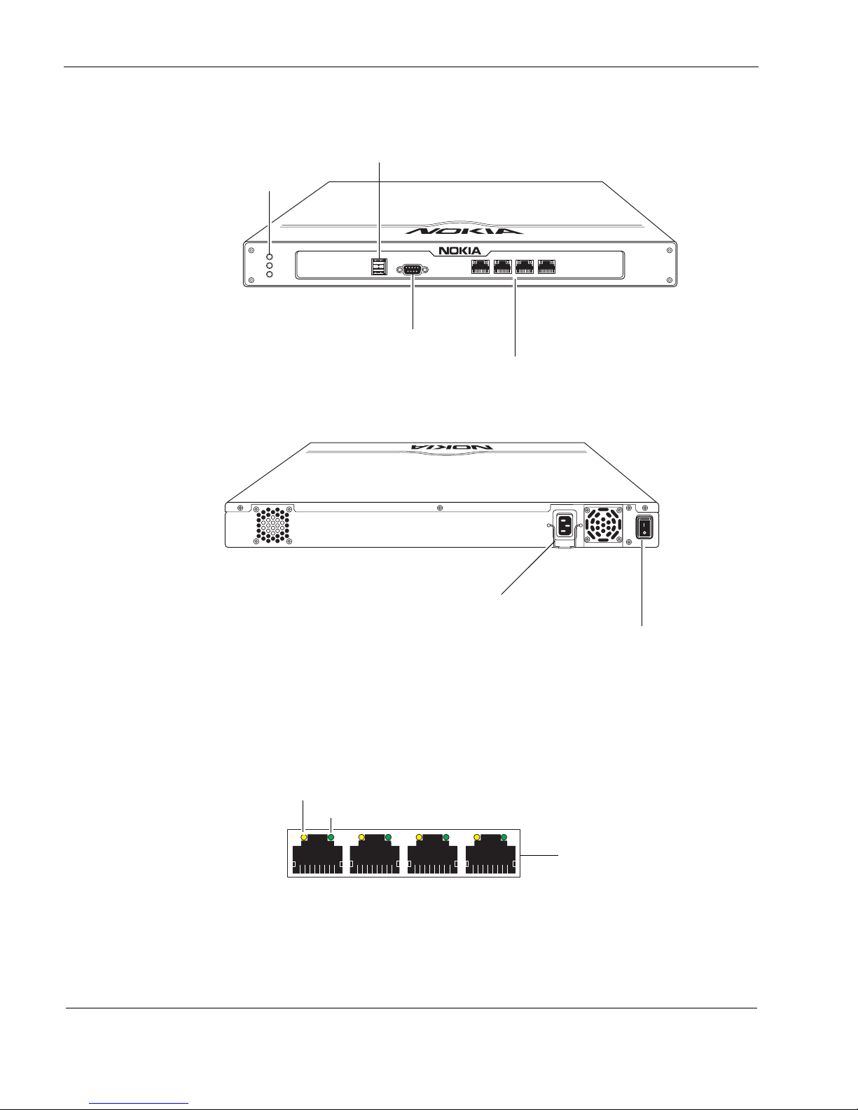
Figure 1 Component Locations Front View
Figure 2 Component Locations Rear View
Built-in Ethernet Ports
Figure 3 shows the layout of the built-in Ethernet ports and LEDs.
Figure 3 Built-In Ethernet Interface Front Panel Details
00662
IP150
AUX CONSOLE
POWER
STATUS
FAULT
1234
Built-in Ethernet ports
(10/100/1000 Mbps)
Status LEDs
Auxiliary (AUX) port
Console port
00663
Power plug
Power switch
00120
Activity LED (yellow)
Link LED (green)
RJ-45 connectors
Nokia IP150 Security Platform Appliance Overview
Nokia IP150 Security Platform Installation Guide 17
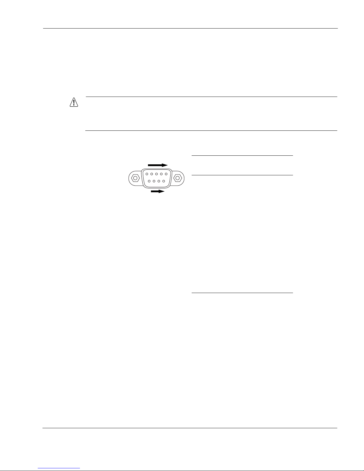
Console and Serial (AUX) Ports
Use the built-in console port to supply the information that makes the appliance available on the
network. Use the built-in USB (AUX) port for RS232-compliant equipment you are using with
your appliance; for example, as a modem connection for managing the appliance. Figure 4
provides pin assignment information for console and serial connections.
Caution
Nokia recommends that you use the console cable that was delivered with your
appliance for your console connection. Otherwise, ensure that the pin assignments for
your cable match those provided in this section.
Figure 4 Pin Assignments for Console Connections
00460
69
5
1
Pin# Assignment
Input or
output
1 not used
2RXD Input
3 TXD Output
4 DTR Output
5GND
6DSR Input
7 RTS Output
8CTS Input
9 not used
1
18 Nokia IP150 Security Platform Installation Guide
Table 2 shows how to match pins at the console connector with output pins on DB9 or DB25
cables you are using with terminal devices or other appropriate equipment.
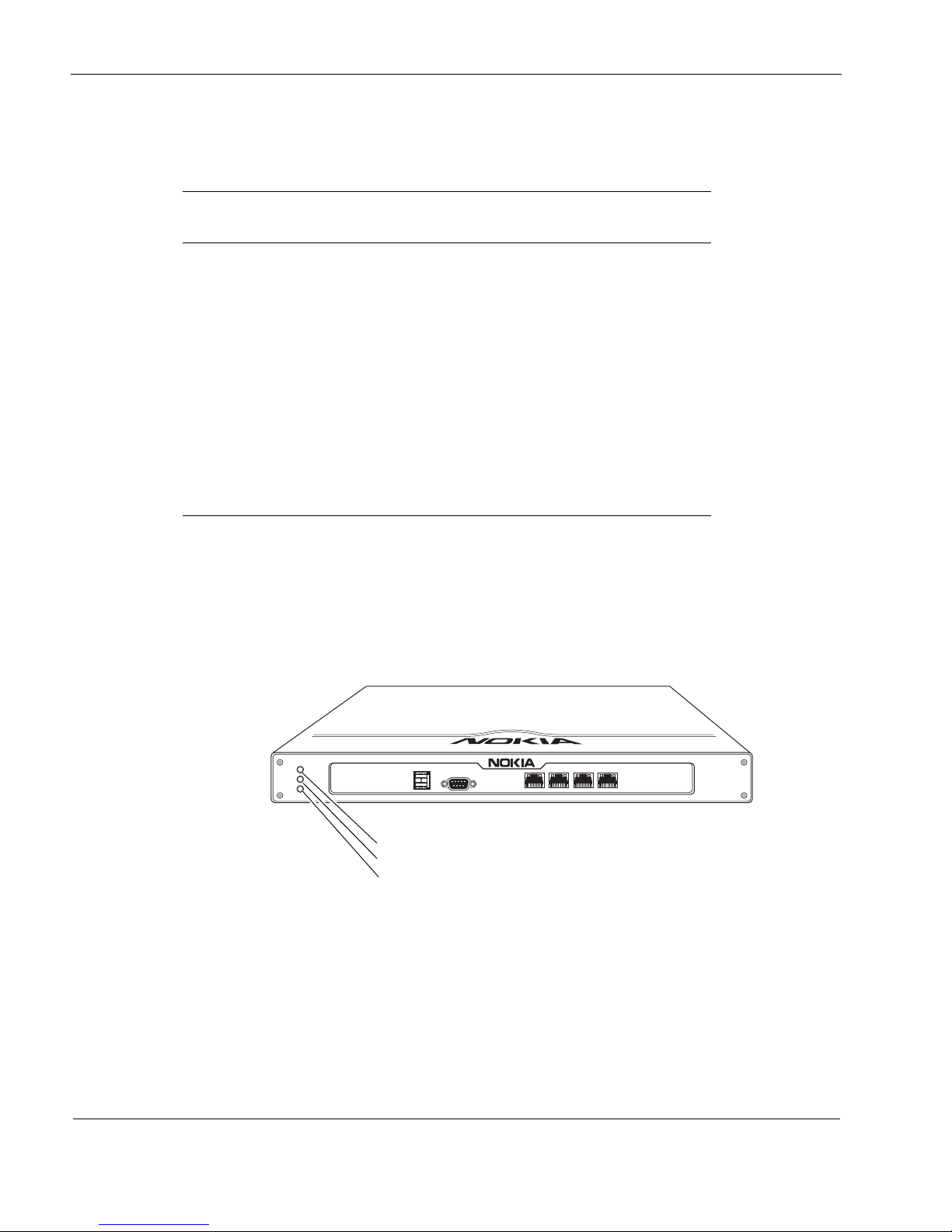
System Status LEDs
You can monitor the basic operation of Nokia IP150 appliances by checking their status LEDs.
The system status LEDs are located on the front panel of the appliance, as Figure 5 shows.
Figure 5 Appliance Status LEDs
Table 2 Pin Assignments for DB9 and DB25 Interface Cables
Console or serial
pin and assignment
DB9 cable output pin and
assignment
DB25 cable output pin and
assignment
Shield (FG) Shield (FG) 1 (FG)
2 (RXD) 3 (TXD) 2 (TXD)
3 (TXD) 2 (RXD) 3 (RXD)
4 (DTR) 6 (DSR) 6 (DSR)
5 (SG) 5 (SG) 7 (SG)
6 (DSR) 4 (DTR) 20 (DTR)
7 (RTS) 8 (CTS) 5 (CTS)
8 (CTS) 7 (RTS) 4 (RTS)
00662
IP150
AUX CONSOLE
POWER
STATUS
FAULT
1234
Power
Status
Fault

Site Requirements
Nokia IP150 Security Platform Installation Guide 19
Table 3 describes the Status LEDs and each status indicator or condition that might display.
For information about the built-in Ethernet interface LEDs, see “Built-in Ethernet Ports” on
page 16.
Site Requirements
Before you install a Nokia IP150 appliance, ensure that your computer room or wiring closet
conforms to the environmental specifications listed in Appendix A, “Technical Specifications.”
Product Disposal
At the end of its useful life, your appliance and all peripherals included with it, including power
cords and cables, must be disposed of in accordance with all applicable national, state, and local
laws and regulations. These devices contain materials and components that must be disposed of
properly. Therefore, to help prevent damage to the environment, Nokia encourages you to
dispose of these devices in an environmentally-friendly manner.
The following resources are available to you to help with equipment-disposal decisions:
Many Nokia products are labeled with information about the materials used in their
manufacture that can help those who will process equipment after you have disposed of it.
The Nokia web site (http://www.nokia.com) provides information about our environmental
programs and practices, which includes details about materials used in manufacturing and
end-of-life practices. You can also find your product’s Eco Declaration, which provides
Table 3 Appliance Status LEDs
Status LED Status Indicator (Color) Description
Power None (off)
Blue
Power off
Power on
Status None (off)
Yellow (steady)
Yellow (blinking)
Normal
Initial boot flash activity
or
Internal voltage problem
Temperature fault
Fault None (off)
Red (steady)
Normal
Initial boot flash activity
or
One or more fans are defective.
1
20 Nokia IP150 Security Platform Installation Guide
basic information on the environmental attributes of the product covering material use,
packaging, disassembly, and recycling.
Contact your local waste management agencies for guidelines specific to your area.
050930
Safety Warnings and Cautions
Warning
To reduce the risk of fire, electric shock, and injury when you use telephone equipment,
follow basic safety precautions. Do not use the product near water.
Caution
Do not place objects over the ventilation holes on the IP150 appliance. The
components might overheat and become damaged.
Caution
For IP150 appliances intended for shipment outside of the United States, the power
cord might not be included. If a power cord is not provided, use a power cord rated at
6A, 250V, maximum 15 feet long, made of HAR cordage and IEC fittings approved by
the country of end use.
Managing IP150 Security Platform Appliances
You can manage Nokia IP150 appliances by using one of the following interfaces:
Nokia Network Voyager—an SSL-secured, Web-based element management interface to
Nokia IP security platforms. Network Voyager is preinstalled on the IP150 appliance and
enabled through the Nokia IPSO operating system. With Network Voyager, you can manage,
monitor, and configure the IP150 appliance from any authorized location within the network
by using a standard Web browser.
For information about how to access Network Voyager and the related reference materials,
see “Using Nokia Network Voyager” on page 35.
The Nokia IPSO command-line interface (CLI)—an SSHv2-secured interface that
enables you to configure Nokia IP security platforms from the command line.
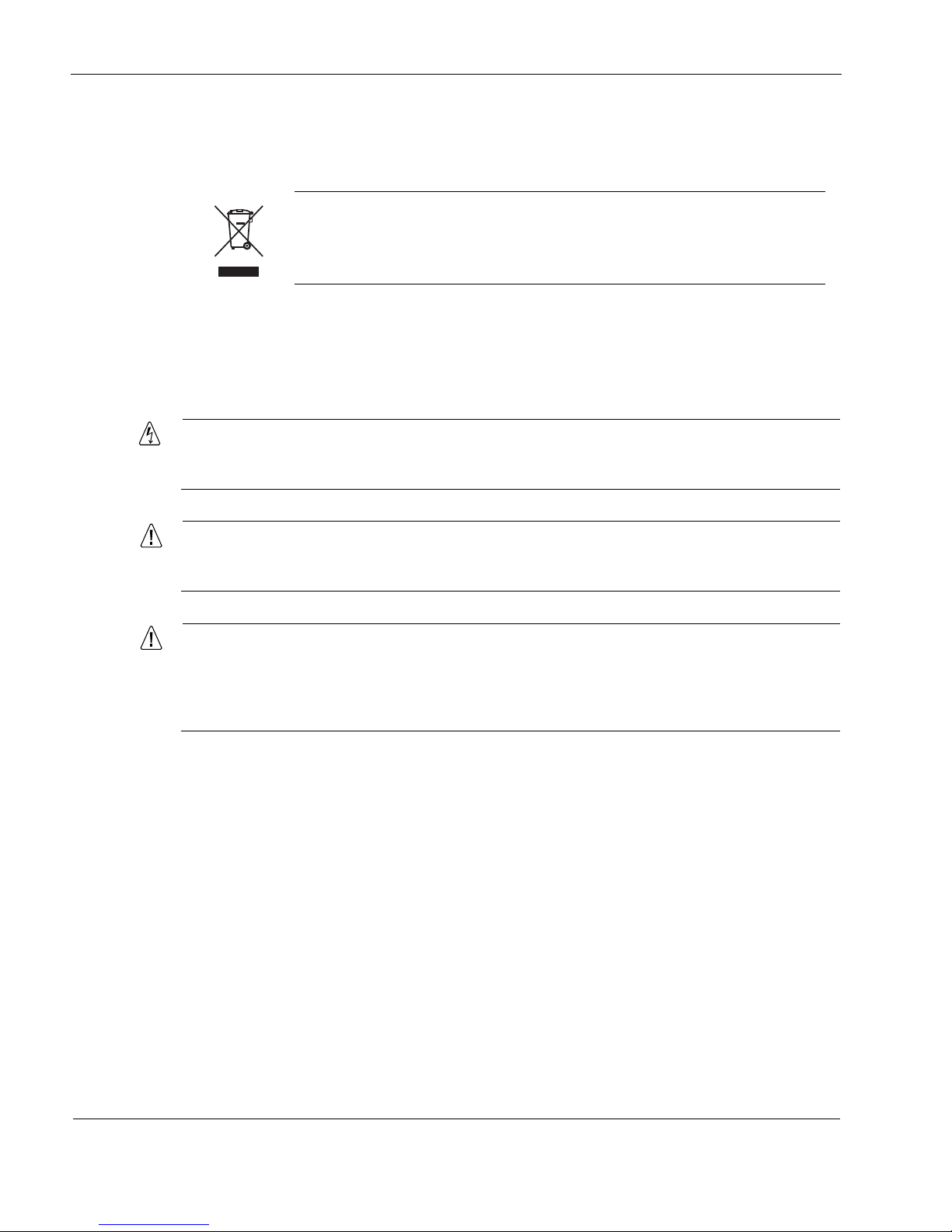
The crossed-out wheeled bin means that within the European Union the product
must be taken to separate collection at the product end-of-life. This applies to your
device but also to any enhancements marked with this symbol. Do not dispose of
these products as unsorted municipal waste.

Managing IP150 Security Platform Appliances
Nokia IP150 Security Platform Installation Guide 21
Everything that you can accomplish with Nokia Network Voyager—to manage and
configure the IP150 appliance—you can also do with the CLI.
For information about how to access the CLI, see the Nokia CLI Reference Guide for the
version of Nokia IPSO you are using.
Nokia Horizon Manager—a secure GUI-based software image management and
monitoring application. With Horizon Manager, you can securely install and upgrade the
Nokia proprietary Nokia IPSO operating system, plus hardware and third-party applications
such as Check Point VPN-1/FireWall-1. Horizon Manager can perform installations and
upgrades on up to 2,500 Nokia IP security platforms, offering administrators the most rapid
and dependable upgrade to Check Point NG.
For information about how to obtain Horizon Manager, see “Nokia Contact Information” on
page 3.

1
22 Nokia IP150 Security Platform Installation Guide

Nokia IP150 Security Platform Installation Guide 23
2 Installing a Nokia IP150 Security
Appliance
Body (b1_body) follows all headings including the chapter title.
You can rack mount Nokia IP150 Security appliances in a one-unit space (1U) in a
standard-configuration appliance rack.
Rack Mounting a Nokia IP150 Appliance
Before you mount the appliance on the rack, install the two side brackets with three screws on
each side as shown in Figure 6. The brackets and screws are included with the materials you
receive with the appliance.
 Loading...