

Page 1

Nokia Customer Care
Service Manual
RM-156 (Nokia N93i)
Mobile Terminal
Part No: 9200670 (Issue 1)
COMPANY CONFIDENTIAL
Copyright © 2007 Nokia. All rights reserved.
Page 2

RM-156
Nokia Customer Care Amendment Record Sheet
Amendment Record Sheet
Amendment No Date Inserted By Comments
Issue 1 01/2007 M. Hautaniemi
Page ii COMPANY CONFIDENTIAL Issue 1
Copyright © 2007 Nokia. All rights reserved.
Page 3

RM-156
Copyright Nokia Customer Care
Copyright
Copyright © 2007 Nokia. All rights reserved.
Reproduction, transfer, distribution or storage of part or all of the contents in this document in any form
without the prior written permission of Nokia is prohibited.
Nokia, Nokia Connecting People, and Nokia X and Y are trademarks or registered trademarks of Nokia
Corporation. Other product and company names mentioned herein may be trademarks or tradenames of
their respective owners.
Nokia operates a policy of continuous development. Nokia reserves the right to make changes and
improvements to any of the products described in this document without prior notice.
Under no circumstances shall Nokia be responsible for any loss of data or income or any special, incidental,
consequential or indirect damages howsoever caused.
The contents of this document are provided "as is". Except as required by applicable law, no warranties of
any kind, either express or implied, including, but not limited to, the implied warranties of merchantability
and fitness for a particular purpose, are made in relation to the accuracy, reliability or contents of this
document. Nokia reserves the right to revise this document or withdraw it at any time without prior notice.
The availability of particular products may vary by region.
IMPORTANT
This document is intended for use by qualified service personnel only.
Issue 1 COMPANY CONFIDENTIAL Page iii
Copyright © 2007 Nokia. All rights reserved.
Page 4

RM-156
Nokia Customer Care Warnings and cautions
Warnings and cautions
Warnings
• IF THE DEVICE CAN BE INSTALLED IN A VEHICLE, CARE MUST BE TAKEN ON INSTALLATION IN VEHICLES FITTED
WITH ELECTRONIC ENGINE MANAGEMENT SYSTEMS AND ANTI-SKID BRAKING SYSTEMS. UNDER CERTAIN FAULT
CONDITIONS, EMITTED RF ENERGY CAN AFFECT THEIR OPERATION. IF NECESSARY, CONSULT THE VEHICLE DEALER/
MANUFACTURER TO DETERMINE THE IMMUNITY OF VEHICLE ELECTRONIC SYSTEMS TO RF ENERGY.
• THE PRODUCT MUST NOT BE OPERATED IN AREAS LIKELY TO CONTAIN POTENTIALLY EXPLOSIVE ATMOSPHERES,
FOR EXAMPLE, PETROL STATIONS (SERVICE STATIONS), BLASTING AREAS ETC.
• OPERATION OF ANY RADIO TRANSMITTING EQUIPMENT, INCLUDING CELLULAR TELEPHONES, MAY INTERFERE
WITH THE FUNCTIONALITY OF INADEQUATELY PROTECTED MEDICAL DEVICES. CONSULT A PHYSICIAN OR THE
MANUFACTURER OF THE MEDICAL DEVICE IF YOU HAVE ANY QUESTIONS. OTHER ELECTRONIC EQUIPMENT MAY
ALSO BE SUBJECT TO INTERFERENCE.
• BEFORE MAKING ANY TEST CONNECTIONS, MAKE SURE YOU HAVE SWITCHED OFF ALL EQUIPMENT.
Cautions
• Servicing and alignment must be undertaken by qualified personnel only.
• Ensure all work is carried out at an anti-static workstation and that an anti-static wrist strap is worn.
• Ensure solder, wire, or foreign matter does not enter the telephone as damage may result.
• Use only approved components as specified in the parts list.
• Ensure all components, modules, screws and insulators are correctly re-fitted after servicing and
alignment.
• Ensure all cables and wires are repositioned correctly.
• Never test a mobile phone WCDMA transmitter with full Tx power, if there is no possibility to perform the
measurements in a good performance RF-shielded room. Even low power WCDMA transmitters may disturb
nearby WCDMA networks and cause problems to 3G cellular phone communication in a wide area.
• During testing never activate the GSM or WCDMA transmitter without a proper antenna load, otherwise
GSM or WCDMA PA may be damaged.
Page iv COMPANY CONFIDENTIAL Issue 1
Copyright © 2007 Nokia. All rights reserved.
Page 5

RM-156
ESD protection Nokia Customer Care
ESD protection
Nokia requires that service points have sufficient ESD protection (against static electricity) when servicing
the phone.
Any product of which the covers are removed must be handled with ESD protection. The SIM card can be
replaced without ESD protection if the product is otherwise ready for use.
To replace the covers ESD protection must be applied.
All electronic parts of the product are susceptible to ESD. Resistors, too, can be damaged by static electricity
discharge.
All ESD sensitive parts must be packed in metallized protective bags during shipping and handling outside
any ESD Protected Area (EPA).
Every repair action involving opening the product or handling the product components must be done under
ESD protection.
ESD protected spare part packages MUST NOT be opened/closed out of an ESD Protected Area.
For more information and local requirements about ESD protection and ESD Protected Area, contact your local
Nokia After Market Services representative.
Issue 1 COMPANY CONFIDENTIAL Page v
Copyright © 2007 Nokia. All rights reserved.
Page 6

RM-156
Nokia Customer Care Care and maintenance
Care and maintenance
This product is of superior design and craftsmanship and should be treated with care. The suggestions below
will help you to fulfil any warranty obligations and to enjoy this product for many years.
• Keep the phone and all its parts and accessories out of the reach of small children.
• Keep the phone dry. Precipitation, humidity and all types of liquids or moisture can contain minerals that
will corrode electronic circuits.
• Do not use or store the phone in dusty, dirty areas. Its moving parts can be damaged.
• Do not store the phone in hot areas. High temperatures can shorten the life of electronic devices, damage
batteries, and warp or melt certain plastics.
• Do not store the phone in cold areas. When it warms up (to its normal temperature), moisture can form
inside, which may damage electronic circuit boards.
• Do not drop, knock or shake the phone. Rough handling can break internal circuit boards.
• Do not use harsh chemicals, cleaning solvents, or strong detergents to clean the phone.
• Do not paint the phone. Paint can clog the moving parts and prevent proper operation.
• Use only the supplied or an approved replacement antenna. Unauthorised antennas, modifications or
attachments could damage the phone and may violate regulations governing radio devices.
All of the above suggestions apply equally to the product, battery, charger or any accessory.
Page vi COMPANY CONFIDENTIAL Issue 1
Copyright © 2007 Nokia. All rights reserved.
Page 7

RM-156
Company Policy Nokia Customer Care
Company Policy
Our policy is of continuous development; details of all technical modifications will be included with service
bulletins.
While every endeavour has been made to ensure the accuracy of this document, some errors may exist. If
any errors are found by the reader, NOKIA MOBILE PHONES Business Group should be notified in writing/email.
Please state:
• Title of the Document + Issue Number/Date of publication
• Latest Amendment Number (if applicable)
• Page(s) and/or Figure(s) in error
Please send to:
NOKIA CORPORATION
Nokia Mobile Phones Business Group
Nokia Customer Care
PO Box 86
FIN-24101 SALO
Finland
E-mail: Service.Manuals@nokia.com
Issue 1 COMPANY CONFIDENTIAL Page vii
Copyright © 2007 Nokia. All rights reserved.
Page 8

RM-156
Nokia Customer Care Battery information
Battery information
Note: A new battery's full performance is achieved only after two or three complete charge and
discharge cycles!
The battery can be charged and discharged hundreds of times but it will eventually wear out. When the
operating time (talk-time and standby time) is noticeably shorter than normal, it is time to buy a new battery.
Use only batteries approved by the phone manufacturer and recharge the battery only with the chargers
approved by the manufacturer. Unplug the charger when not in use. Do not leave the battery connected to
a charger for longer than a week, since overcharging may shorten its lifetime. If left unused a fully charged
battery will discharge itself over time.
Temperature extremes can affect the ability of your battery to charge.
For good operation times with Ni-Cd/NiMh batteries, discharge the battery from time to time by leaving the
product switched on until it turns itself off (or by using the battery discharge facility of any approved accessory
available for the product). Do not attempt to discharge the battery by any other means.
Use the battery only for its intended purpose.
Never use any charger or battery which is damaged.
Do not short-circuit the battery. Accidental short-circuiting can occur when a metallic object (coin, clip or
pen) causes direct connection of the + and - terminals of the battery (metal strips on the battery) for example
when you carry a spare battery in your pocket or purse. Short-circuiting the terminals may damage the battery
or the connecting object.
Leaving the battery in hot or cold places, such as in a closed car in summer or winter conditions, will reduce
the capacity and lifetime of the battery. Always try to keep the battery between 15°C and 25°C (59°F and 77°
F). A phone with a hot or cold battery may temporarily not work, even when the battery is fully charged.
Batteries' performance is particularly limited in temperatures well below freezing.
Do not dispose of batteries in a fire!
Dispose of batteries according to local regulations (e.g. recycling). Do not dispose as household waste.
Page viii COMPANY CONFIDENTIAL Issue 1
Copyright © 2007 Nokia. All rights reserved.
Page 9

RM-156
Nokia N93i Service Manual Structure Nokia Customer Care
Nokia N93i Service Manual Structure
1 General Information
2 Parts Lists and Component Layouts
3 Phoenix Service Software Instructions
4 Service Tools and Service Concepts
5 Disassembly and reassembly instructions
6 BB Troubleshooting and Tuning Guide
7 RF Troubleshooting and Tuning Guide
8 Camera Module Troubleshooting
9 System Module
10 Schematics
Issue 1 COMPANY CONFIDENTIAL Page ix
Copyright © 2007 Nokia. All rights reserved.
Page 10

RM-156
Nokia Customer Care Nokia N93i Service Manual Structure
(This page left intentionally blank.)
Page x COMPANY CONFIDENTIAL Issue 1
Copyright © 2007 Nokia. All rights reserved.
Page 11

Nokia Customer Care
1 — General Information
Issue 1 COMPANY CONFIDENTIAL Page 1 –1
Copyright © 2007 Nokia. All rights reserved.
Page 12

RM-156
Nokia Customer Care General Information
(This page left intentionally blank.)
Page 1 –2 COMPANY CONFIDENTIAL Issue 1
Copyright © 2007 Nokia. All rights reserved.
Page 13

RM-156
General Information Nokia Customer Care
Table of Contents
RM-156 product selection......................................................................................................................................1–5
Product features and sales package.....................................................................................................................1–5
Mobile enhancements............................................................................................................................................1–8
Technical specifications...................................................................................................................................... 1–11
Transceiver general specifications ............................................................................................................... 1–11
Main RF characteristics for triple-band (EGSM900/GSM1800/GSM1900) and WCDMA phones ................ 1–11
Operating times.............................................................................................................................................. 1–12
Environmental conditions ............................................................................................................................. 1–12
List of Tables
Table 1 Audio..........................................................................................................................................................1–8
Table 2 Car...............................................................................................................................................................1–9
Table 3 Carrying................................................................................................................................................... 1–10
Table 4 Data ......................................................................................................................................................... 1–10
Table 5 Messaging............................................................................................................................................... 1–10
Table 6 Power...................................................................................................................................................... 1–10
Table 7 Environmental conditions..................................................................................................................... 1–12
List of Figures
Figure 1 View of RM-156........................................................................................................................................1–5
Issue 1 COMPANY CONFIDENTIAL Page 1 –3
Copyright © 2007 Nokia. All rights reserved.
Page 14

RM-156
Nokia Customer Care General Information
(This page left intentionally blank.)
Page 1 –4 COMPANY CONFIDENTIAL Issue 1
Copyright © 2007 Nokia. All rights reserved.
Page 15
RM-156
General Information Nokia Customer Care
RM-156 product selection
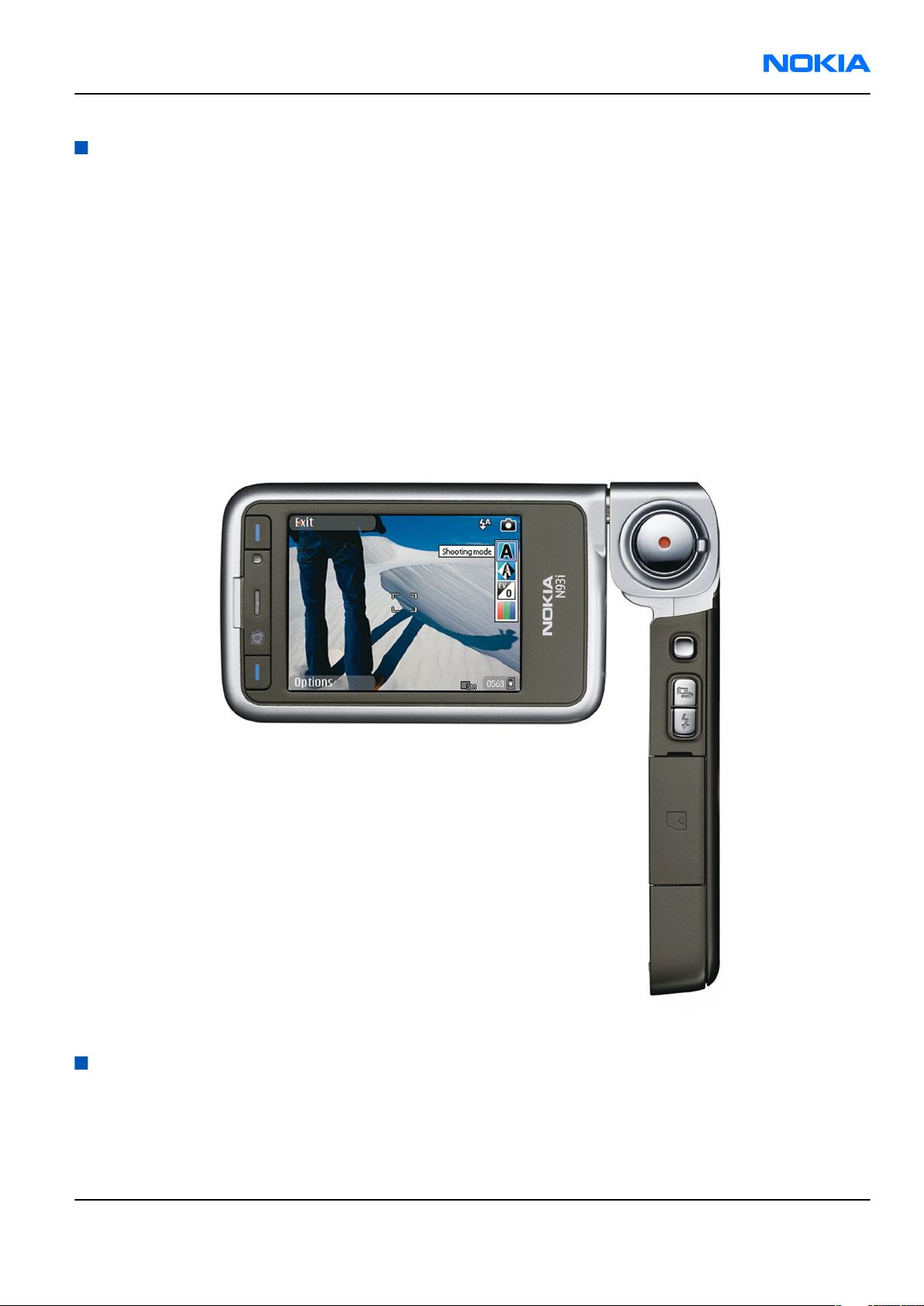
RM-156 is a WCDMA/GSM dual mode handportable phone, supporting WCDMA 2100/EGSM 900/1800/1900.
According to GSM standard 05.05 it responds to class 4 (max. 2 W) in EGSM900, class 1 (1 W) in GSM1800 and
class 1 in GSM1900. The device supports EGPRS (EDGE) class B as well as Bluetooth 2.0 + EDR (Enhanced Data
Rate) standard. The handset has a full phase 2 Type Approval and it complies with the GSM Type Approval.
RM-156 also has a full CE approval and FCC (Federal Communications Commission) approval.
RM-156 supports two-way video calls with two integrated cameras. It is an MMS (Multimedia Messaging
Service) enabled phone with a large bright colour display and an integrated 3.0 megapixel rear camera (3x
optical zoom) and a CIF digital front camera.
The MMS implementation follows the OMA (Open Mobile Alliance) MMS standard release 1.2.
WAP 2.0 compatible browser supports XHTML Mobile Profile (MP) and uses a TCP/IP stack to communicate
with a gateway in network.
RM-156 uses a Symbian 9.1 operating system and support also MIDP (Mobile Information Device Profile) Java
2.0 & CLDC 1.1 (Connected Limited Device Configuration), providing a good platform for 3rd party applications.
Figure 1 View of RM-156
Product features and sales package
Hardware characteristics
• Dual-mode: WCDMA2100/EGSM900/GSM1800/GSM1900 MHz
• Speech Codecs supported: AMR/FR/EFR
Issue 1 COMPANY CONFIDENTIAL Page 1 –5
Copyright © 2007 Nokia. All rights reserved.
Page 16

RM-156
Nokia Customer Care General Information
• WCDMA 2100 MHz with simultaneous voice and packet data (PS max speed DL/UL= 384/384kbps, CS max
speed 64kpbs)
• Dual Transfer Mode (DTM) support for simultaneous voice and packet data connection in GSM/EDGE
networks. Simple class A, multi slot class 11, max data speed to be: 177.6/118.4 kbits/s
• EGPRS class B, multi slot class 32, (5 Rx + 3 Tx / Max Sum 6), max speed DL/UL= 296 / 177.6 kbits/s.
• GPRS class B, multi slot class 32, (5 Rx + 3 Tx / Max Sum 6), max speed DL/UL= 107/64.2 kbits/s.
• 3.2 megapixel camera (2048 x 1536) with 3x continuous optical zoom and up to 20x digital zoom; High
quality lens solution.
• Stereo microphone.
• LED Flash and red recording indicator LED.
• Sub camera, CIF (352 x 288) sensor.
• Large bright 2.4” QVGA (240 x 320 pixels) TFT colour display with 16.7M colours and wide viewing angle.
Ambient light detector - used to optimize display brightness and power consumption
• Sub-display – 1.1” PM-OLED colour display (128x36), 65,536 colours.
• Keys : ITU numeric keys, Send/End keys, S60 keys (Application, Edit, Clear, 5-way navi key), Operator/
Multimedia key, Left/Right selection keys, Upper/Lower Landscape selection keys, Shutter key, Zoom key,
Side 5-way navi key, Camera mode key, Flash key, Power key.
• 50 Mbytes internal user memory
• Internal antennas
• Integrated handsfree speaker
• Vibrator
• Stereo FM radio
• (U)SIM chip slot (1.8 and 3.0 V)
• TV output support (PAL/NTSC)
• miniSD memory card support (hot swappable)
• Pop-Port™ interface with USB 2.0 connectivity
• WLAN - IEEE802.11 g /b
• Bluetooth wireless technology 2.0
• Infrared
Software platform
• Symbian 9.1
• Nokia Series 60 3.0 User Interface : C++ and Java SDKs
User interface
• Imaging
• Capture
• Video: Record DVD-like MPEG-4 VGA 30 fps movies with stereo audio and stabilization.
• Photos: Take high quality 3.2 megapixel pictures. User settings for Scene, Flash, White Balance,
Exposure and Colour tone. Self timer support.
• Sequence mode: Capture 6 pictures in 2 seconds.
• Edit
• Photo editor
Page 1 –6 COMPANY CONFIDENTIAL Issue 1
Copyright © 2007 Nokia. All rights reserved.
Page 17

RM-156
General Information Nokia Customer Care
• Video editor
• View
• Slideshow from Gallery
• Show photo and videos on TV
• Share
• Sending via Bluetooth, Infrared, MMS, e-mail
• Online Album : Image/Video uploading from Gallery
• Print
• Nokia XpressPrint – direct printing from phone, memory card or via online album.
• Store
• Gallery with album support
• Nokia Lifeblog
• Messaging
• • Multimedia Messaging
• Concatenated SMS (MO/MT)
• E-mail (SMTP, IMAP4, POP3)
• Predictive text input
• Music
• Music player : Supports MP3/AAC/WMA with playlists
• Stereo FM radio + Visual radio support
• PIM
• Contacts, Calendar, To-do, Notes
• Recorder, Calculator, Clock, Converter
• Synchronization
• Local/Remote (using SyncML)
• Data: Calendar, Contacts, To-do, Notes, E-mail
• PC Applications: Microsoft Outlook (98, 2000, 2002, 2003), Outlook Express, Lotus Organizer (5.0, 6.0),
Lotus Notes (5.0, 6.0)
• Phone
• 3GPP Rel ’99 compliant
• Voice dialling (Flexible SIND)
• Voice commands
• Push to Talk (PoC)
• Java: MIDP2.0
• Browser : full web browser
• Personalization
• Themes
• SP-MIDI (64 polyphonics), True Tones
• Location based services
• MT-LR Control Plane Cell-Id Positioning with DTAP LCS Location Notification
Issue 1 COMPANY CONFIDENTIAL Page 1 –7
Copyright © 2007 Nokia. All rights reserved.
Page 18
RM-156
Nokia Customer Care General Information
Sales package
• Transceiver with lens cover
• BL-5F li-ion battery cell
• Mini-SD memory card (1GB)
• CA-53 connectivity cable (USB)
• CA-64U video out cable
• AC-4 travel charger
• CP-83 carrying case
• CP-84 wrist strap
• HS-23 stereo headset
• User guide, Quick start guide, and add-on application guide
• DVD-ROM (with PC Suite and other applications)
Mobile enhancements
Table 1 Audio
Enhancement Type
Headsets
Wireless Headset HS-11W
HS-26W
HS-37W
HDW-3
BH-300 (HS-50W)
HS-36W
Wireless Clip-on Headset HS-21W
Wireless Image Headset HS-13W
Wireless Boom Headset HS-4W
Bluetooth Headset BH-800 (HS-24W)
BH-900 (HS-25W)
BH-700(HS-57W)
BH-200 (HS-58W)
BH-600(HS-59W)
BH-301 (HS-51W) PR2
BH-302 (HS-73W)
BH-202 (HS-38W)
BH-801 (HS-64W) PR2
BH-500 (HS-39W) PR2
BH-501 (HS-71W)
Page 1 –8 COMPANY CONFIDENTIAL Issue 1
Copyright © 2007 Nokia. All rights reserved.
Page 19
RM-156
General Information Nokia Customer Care
Enhancement Type
Wireless Stereo Headset HS-12W (PR-2)
HS-34W (PR-2)
Boom Headset HDB-4
Headset HS-5
Activity Stereo Headset HS-8
Stereo Headset HS-23
HDS-3
Stereo Fashion Headset HS-3
Activity Stereo Headset HS-29
Display Headset HS-6
Music Headset HS-20
Fashion Stereo Headset HS-31
Stereo Headset HDS-3
Music Display Headset HS-69
Other
Music Stand MD-1
Audio Adapter AD-15
AD-46
Inductive Loopset LPS-4
Mini Speaker MD-4
Table 2 Car
Enhancement Type
Car kits
Advanced Car Kit CK-7W
CK-20W
Wireless Car Kit CK-1W
Car Kit N616
Other car enhancements
Mobile Charger DC-4
Headrest Handsfree BHF-3
Wireless Plug-in Car Handsfree HF-3
HF-6W
HF-35W
HF-33W (PR2)
Issue 1 COMPANY CONFIDENTIAL Page 1 –9
Copyright © 2007 Nokia. All rights reserved.
Page 20
RM-156
Nokia Customer Care General Information
Enhancement Type
Universal Mobile Holder CR-39
Wireless GPS Module LD-3W
GPS module LD-2
Table 3 Carrying
Enhancement Type
Carrying case CP-83
Wrist strap CP-84
Table 4 Data
Enhancement Type
Connectivity Cable CA-53
Video out cable CA-64U
Charging Data Cable CA-70
Wireless GPS Module LD-1W
Memory Cards Mini SD 64MB
Mini-SD 128MB
Mini-SD 256MB
Mini-SD 512MB
Mini-SD 1GB
Mini SD 2GB MU-36
TTY Adapter HDA-10
Table 5 Messaging
Enhancement Type
Wireless Keyboard SU-8W
Digital Pen SU-1B
SU-27W
Table 6 Power
Enhancement Type
Chargers
Travel Charger AC-4
AC-5
Compact charger AC-3
Page 1 –10 COMPANY CONFIDENTIAL Issue 1
Copyright © 2007 Nokia. All rights reserved.
Page 21
RM-156
General Information Nokia Customer Care
Enhancement Type
Charging Adapter CA-44
Batteries
Battery BL-5F
Technical specifications
Transceiver general specifications
Unit Dimensions (L x W x T) Weight (g)
Transceiver with BL-5F
950 mAh li-ion battery
back
46.2 x 40 x 5.4 21 9.98
Volume (cm3)
Main RF characteristics for triple-band (EGSM900/GSM1800/GSM1900) and WCDMA phones
Parameter Unit
Cellular system EGSM900, GSM1800/1900 and WCDMA
Rx frequency band EGSM900: 925 - 960 MHz
GSM1800: 1805 - 1880 MHz
GSM1900: 1930 - 1990 MHz
WCDMA: 2110 - 2170 MHz
Tx frequency band EGSM900: 880 - 915 MHz
GSM1800: 1710 - 1785 MHz
GSM1900: 1850 - 1910 MHz
WCDMA: 1920 - 1980 MHz
Output power GSM900: +5 … +33dBm/3.2mW … 2W
GSM1800: +0 … +30dBm/1.0mW … 1W
GSM1900: +0 … +30dBm/1.0mW … 1W
WCDMA -50 … 21 dBm
Number of RF channels GSM900: 125
GSM1800: 375
GSM1900: 300
WCDMA: 277
Channel spacing 200 kHz
Number of Tx power levels GSM900: 15
GSM1800: 16
GSM1900: 16
Issue 1 COMPANY CONFIDENTIAL Page 1 –11
Copyright © 2007 Nokia. All rights reserved.
Page 22
RM-156
Nokia Customer Care General Information
Operating times
Battery Talk time Stand-by Still
BL-5F
950 mAh
3.1 - 3.9
hrs (GSM)
1.7 - 3.3
hrs
(WCDMA )
Note: Operating times with in-box battery. Variation in operation times will occur depending on
SIM card, network settings and usage.
9.3 - 11.8
days (GSM)
7.8 - 9.4
days
(WCDMA)
Charging times
1 h 15 min
Environmental conditions
Table 7 Environmental conditions
Images
up to 291
pictures
(3M, flash
off)
up to 112
min (VGA,
30fps)
AC-4
Video
capture
Video call
talk time
up to 107
min
Video
playback
time
up to 205
min (VGA,
30fps)
Music
playback
time
up to 6.3
hours
(offline
mode)
Environmental
condition
Normal operation
Reduced performance
Charging allowed
Long term storage
conditions
Ambient temperature Notes
-15oC...+55oC
-20oC...-15oC
+35oC...+55oC
-25oC...+50oC
0oC...+85oC
Specifications fulfilled
Main camera performance reduced.
Page 1 –12 COMPANY CONFIDENTIAL Issue 1
Copyright © 2007 Nokia. All rights reserved.
Page 23

Nokia Customer Care
2 — Parts Lists and Component
Layouts
Issue 1 COMPANY CONFIDENTIAL Page 2 –1
Copyright © 2007 Nokia. All rights reserved.
Page 24

RM-156
Nokia Customer Care Parts Lists and Component Layouts
(This page left intentionally blank.)
Page 2 –2 COMPANY CONFIDENTIAL Issue 1
Copyright © 2007 Nokia. All rights reserved.
Page 25

RM-156
Parts Lists and Component Layouts Nokia Customer Care
Table of Contents
Spare parts overview and exploded view............................................................................................................2–5
Mechanical spare parts list ....................................................................................................................................2–6
Component parts lists and layouts.......................................................................................................................2–8
Engine PWB component parts list ...................................................................................................................2–8
Engine PWB component layouts................................................................................................................... 2–28
UI PWB component parts list ........................................................................................................................ 2–30
UI PWB component layout............................................................................................................................. 2–31
Flip PWB component parts list...................................................................................................................... 2–32
Flip PWB component layouts ........................................................................................................................ 2–34
Mic PWB component parts list ...................................................................................................................... 2–35
Mic PWB component layout .......................................................................................................................... 2–36
List of Tables
Table 8 Component parts list 1UV_060a ..............................................................................................................2–8
Table 9 Component parts list 1UX_030a............................................................................................................ 2–30
Table 10 Component parts list 1UY_0301a ....................................................................................................... 2–32
Table 11 Component parts list 1YQ_030a ......................................................................................................... 2–35
List of Figures
Figure 2 Component layout - Bottom (1UV_060a) ........................................................................................... 2–28
Figure 3 Component layout - Top (1UV_060a).................................................................................................. 2–29
Figure 4 Component layout - Top (1UX_030a).................................................................................................. 2–31
Figure 5 Component layout - Bottom (1UY_0301a) ......................................................................................... 2–34
Figure 6 Component layout - Top (1UY_0301a)................................................................................................ 2–35
Figure 7 Component layout - Top (1YQ_030a).................................................................................................. 2–36
Issue 1 COMPANY CONFIDENTIAL Page 2 –3
Copyright © 2007 Nokia. All rights reserved.
Page 26

RM-156
Nokia Customer Care Parts Lists and Component Layouts
(This page left intentionally blank.)
Page 2 –4 COMPANY CONFIDENTIAL Issue 1
Copyright © 2007 Nokia. All rights reserved.
Page 27
RM-156
Parts Lists and Component Layouts Nokia Customer Care
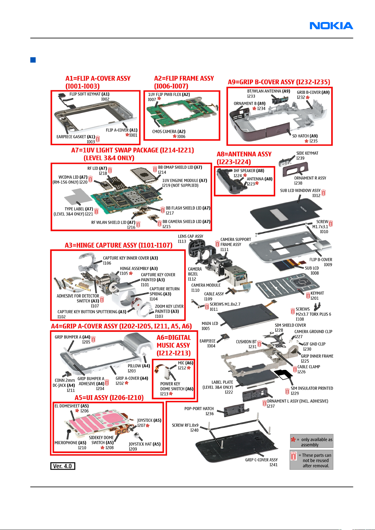
Spare parts overview and exploded view
Issue 1 COMPANY CONFIDENTIAL Page 2 –5
Copyright © 2007 Nokia. All rights reserved.
Page 28
RM-156
Nokia Customer Care Parts Lists and Component Layouts
Mechanical spare parts list
Note: For Nokia product codes, please refer to the latest Service Bulletins on the Partner Website (PWS). To ensure you are always
using the latest codes, please check the PWS on a daily basis.
ITEM/ CIRCUIT
REF.
QTY SPARE PART DESCRIPTION
A1 1 FLIP A-COVER ASSY (I001 - I003)
I001 1 FLIP A-COVER
I002 1 FLIP SOFT KEYMAT
I003 1 EARPIECE GASKET
I004 1 EARPIECE
I005 1 MAIN LCD
A2 1 FLIP FRAME ASSY (I006 - I007)
I006 1 CMOS CAMERA
I007 1 1 UY FLIP PWB FLEX
I008 1 SUB LCD
I009 1 FLIP B-COVER
I010 4 SCREW M1.7 x 3.1
I011 2 SCREW M1.8x2.7
I012 1 SUB LCD WINDOW ASSY
A3 1 HINGE CAPTURE ASSY (I101 - I107)
I101 1 CAPTURE KEY COVER PAINTED
I102 1 CAPTURE KEY BUTTON SPUTTERING
I103 1 ZOOM KEY LEVER PAINTED
I104 1 CAPTURE RETURN SPRING
I105 1 HINGE ASSEMBLY
I106 1 CAPTURE KEY INNER COVER
I107 1 ADHESIVE FOR DETECTOR SWITCH
I108 2 SCREW M2X3.7 TORX PLUS 6
I109 1 CABLE ASSY
I110 1 CAMERA MODULE
I111 1 CAMERA SUPPORT FRAME ASSY
I112 1 CAMERA BEZEL
I113 1 LENS CAP ASSY
I201 1 KEYMAT
Page 2 –6 COMPANY CONFIDENTIAL Issue 1
Copyright © 2007 Nokia. All rights reserved.
Page 29
RM-156
Parts Lists and Component Layouts Nokia Customer Care
ITEM/ CIRCUIT
REF.
A4 1 GRIP A-COVER ASSY (I202 - I205, I211, A5, A6)
I202 1 GRIP A-COVER
I203 1 PILLOW
I204 1 GRIP BUMPER A ADHESIVE
I205 1 GRIP BUMPER A
A5 1 UI ASSY (I206 - I210)
I206 1 EL DOMESHEET ASSY
I207 1 JOYSTICK
I208 1 SIDEKEY DOME SWITCH
I209 1 JOYSTICK HAT
I210 1 MICROPHONE
I211 1 CONN 2mm DC-JACK
A6 1 DIGITAL MIC ASSY (I212 - I213)
I212 2 MIC
QTY SPARE PART DESCRIPTION
I213 1 POWER KEY DOME SWITCH
A7 1 1UV LIGHT SWAP PACKAGE (I214 - I221)
I214 1 BB OMAP SHIELD LID
I215 1 BB CAMERA SHIELD LID
I216 1 RF WLAN SHIELD LID
I217 1 BB FLASH SHIELD LID
I218 1 RF LID
I219 1 1UV ENGINE MODULE
I220 1 WCDMA LID (RM-156 only)
I221 1 TYPE LABEL
I222 1 LABEL PLATE
A8 1 ANTENNA ASSY (I223 - I224)
I223 1 ANTENNA
I224 1 IHF SPEAKER
I225 1 GRIP INNER FRAME
I226 1 CABLE CLAMP
I227 1 CAMERA GROUND CLIP
I228 1 SIM SHIELD COVER
I229 1 SIM INSULATOR PRINTED
Issue 1 COMPANY CONFIDENTIAL Page 2 –7
Copyright © 2007 Nokia. All rights reserved.
Page 30
RM-156
Nokia Customer Care Parts Lists and Component Layouts
ITEM/ CIRCUIT
REF.
QTY SPARE PART DESCRIPTION
I230 1 GIF GND CLIP
I231 1 CUSHION BT
A9 1 GRIP B-COVER ASSY (I232 - I235)
I232 1 GRIP B-COVER
I233 1 BT/WLAN ANTENNA
I234 1 ORNAMENT B
I235 1 SD HATCH
I236 1 POP-PORT HATCH
I237 1 ORNAMENT L ASSY (incl. Adhesive)
I238 1 ORNAMENT R ASSY
I239 1 SIDE KEYMAT
I240 4 SCREW RF 1.8X9
I241 1 GRIP C-COVER ASSY
Component parts lists and layouts
Engine PWB component parts list
Table 8 Component parts list 1UV_060a
Note: For Nokia product codes, please refer to the latest Service Bulletins on the Partner Website (PWS). To ensure you are always
using the latest codes, please check the PWS on a daily basis.
Item Side Grid ref. Type Description and value
SHIELD_040_0136
A1 Top G 7
A2 Top G 4 SHIELD_WCDMA
A3 Bot F 12
A4 Top F 14
A5 Bot D 14
A6 Bot I 14
93 RF SHIELD ASSEMBLY ~ ~
WCDMA-SHIELD
ASSEMBLY ~ ~
SHIELD_040_023057RF WLAN SHIELD ASSY
040-023057 ~ ~
SHIELD_040_023051BB OMAP SHIELD ASSY
040-023051 ~ ~
SHIELD_040_023054BB FLASH SHIELD ASSY
040-023054 ~ ~
SHIELD_040_023048BB CAMERA SHELD ASSY
040-023048 ~ ~
CLAPTON EMC
B8100 Top D 3
MIC_OBE_415S42_
RC3310CL
MICROPHONE MOD
-42DB ~ ~
CHIPCAP X5R 100N K
C1001 Top F 15 0402C_H0.6
16V 0402 100n 16V
Page 2 –8 COMPANY CONFIDENTIAL Issue 1
Copyright © 2007 Nokia. All rights reserved.
Page 31

RM-156
Parts Lists and Component Layouts Nokia Customer Care
Item Side Grid ref. Type Description and value
C2000 Top C 4 0402C Chipcap 5% NP0 27p 50V
Chipcap X7R 10% 16V
C2002 Bot D 7 0402C
C2003 Bot D 7 0402C
C2033 Bot C 5 0402C Chipcap 5% NP0 10p 50V
C2034 Bot C 5 0402C Chipcap 5% NP0 10p 50V
C2035 Bot C 5 0402C Chipcap 5% NP0 10p 50V
C2036 Bot C 5 0402C Chipcap 5% NP0 10p 50V
C2039 Top C 4 0603C_H0.95
C2041 Top I 13 0402C Chipcap 5% NP0 68p 50V
C2042 Top J 13 0402C_H0.6
0402 10n 16V
Chipcap X7R 10% 16V
0402 10n 16V
CHIPCAP X5R 470N K
25V 0603 470n 25V
CHIPCAP X5R 100N K
16V 0402 100n 16V
CHIPCAP X5R 100N K
C2043 Bot C 7 0402C_H0.6
C2044 Bot D 8 0402C Chipcap 5% NP0 22p 50V
C2045 Bot D 8 0402C Chipcap 5% NP0 22p 50V
TANT_C_6.2X3.4_H
C2070 Top C 4
C2151 Bot F 4 0402C
C2152 Bot F 5 0402C
C2153 Bot F 5 0402C
C2155 Bot I 4 0402C
C2156 Bot I 4 0402C
C2157 Bot I 4 0402C
1.7
16V 0402 100n 16V
CHIPTCAP 150U M 10V
6X3.2X1.5 150u_10V 10V
Chipcap X7R 10% 50V
0402 1n0 50V
Chipcap X7R 10% 50V
0402 1n0 50V
Chipcap X7R 10% 50V
0402 1n0 50V
Chipcap X7R 10% 50V
0402 1n0 50V
Chipcap X7R 10% 50V
0402 1n0 50V
Chipcap X7R 10% 50V
0402 1n0 50V
CHIPCAP X5R 100N K
C2158 Top E 15 0402C_H0.6
C2165 Top D 11 0402C Chipcap 5% X7R 820p 50V
C2170 Top E 4 0402C Chipcap 5% NP0 22p 50V
C2171 Bot J 5 0402C Chipcap 5% NP0 27p 50V
C2172 Bot G 5 0402C Chipcap 5% NP0 27p 50V
Issue 1 COMPANY CONFIDENTIAL Page 2 –9
Copyright © 2007 Nokia. All rights reserved.
16V 0402 100n 16V
Page 32

RM-156
Nokia Customer Care Parts Lists and Component Layouts
Item Side Grid ref. Type Description and value
CHIPCAP X5R 100N K
C2750 Bot H 14 0402C_H0.6
C4200 Top C 14 0405_DUAL
C4201 Top D 15 0805C
C4203 Top D 14 0402C
C4204 Top C 14 0402C_H0.6
C4205 Top D 13 0805C
C4206 Top C 15 0402C
C4207 Top I 15 0402C_H0.6
16V 0402 100n 16V
CHIPCAP NETWORK X5R
2X1U5 K 6V3 0405 2x1u5 6.3V
CHIPCAP X5R 22U M 6V3
0805 22u 6V3
CHIPCAP X5R 1U5 K 4V
0402 1u5 4V
CHIPCAP X5R 100N K
16V 0402 100n 16V
CHIPCAP X5R 22U M 6V3
0805 22u 6V3
CHIPCAP X5R 1U5 K 4V
0402 1u5 4V
CHIPCAP X5R 100N K
16V 0402 100n 16V
C4208 Top D 14 0405_DUAL
C4209 Top D 13 0805C
C4211 Top D 14 0402C
C4212 Top D 14 0402C
C4213 Top C 15 0402C_H0.6
C4214 Top C 15 0402C
C4215 Top C 15 0405_DUAL
C4216 Top D 14 0805C
C4219 Top H 15 0402C_H0.6
C4800 Top F 14 0402C_H0.6
CHIPCAP NETWORK X5R
2X1U5 K 6V3 0405 2x1u5 6.3V
CHIPCAP X5R 22U M 6V3
0805 22u 6V3
CHIPCAP X5R 1U5 K 4V
0402 1u5 4V
CHIPCAP X5R 1U5 K 4V
0402 1u5 4V
CHIPCAP X5R 100N K
16V 0402 100n 16V
CHIPCAP X5R 1U5 K 4V
0402 1u5 4V
CHIPCAP NETWORK X5R
2X1U5 K 6V3 0405 2x1u5 6.3V
CHIPCAP X5R 22U M 6V3
0805 22u 6V3
CHIPCAP X5R 100N K
16V 0402 100n 16V
CHIPCAP X5R 100N K
16V 0402 100n 16V
CHIPCAP X5R 100N K
C4801 Top G 15 0402C_H0.6
C4802 Top H 12 0402C_H0.6
Page 2 –10 COMPANY CONFIDENTIAL Issue 1
Copyright © 2007 Nokia. All rights reserved.
16V 0402 100n 16V
CHIPCAP X5R 100N K
16V 0402 100n 16V
Page 33

RM-156
Parts Lists and Component Layouts Nokia Customer Care
Item Side Grid ref. Type Description and value
CHIPCAP X5R 100N K
C4803 Top I 13 0402C_H0.6
C4804 Top F 14 0402C_H0.6
C4806 Top F 13 0402C_H0.6
C4807 Top F 12 0402C_H0.6
C4808 Top G 12 0402C_H0.6
C4813 Top I 15 0402C_H0.6
C4814 Top G 12 0402C
C4816 Top F 13 0402C_H0.6
16V 0402 100n 16V
CHIPCAP X5R 100N K
16V 0402 100n 16V
CHIPCAP X5R 100N K
16V 0402 100n 16V
CHIPCAP X5R 100N K
16V 0402 100n 16V
CHIPCAP X5R 100N K
16V 0402 100n 16V
CHIPCAP X5R 100N K
16V 0402 100n 16V
CHIPCAP X5R 1U5 K 4V
0402 1u5 4V
CHIPCAP X5R 100N K
16V 0402 100n 16V
C4817 Top G 12 0402C_H0.6
C4818 Top H 12 0402C_H0.6
C4819 Top H 12 0402C_H0.6
C4820 Top F 15 0402C_H0.6
C4821 Top G 15 0402C_H0.6
C4822 Top H 15 0402C_H0.6
C4823 Top I 14 0402C_H0.6
C4824 Top F 13 0402C_H0.6
C4825 Top F 15 0402C
C4826 Top F 14 0402C
CHIPCAP X5R 100N K
16V 0402 100n 16V
CHIPCAP X5R 100N K
16V 0402 100n 16V
CHIPCAP X5R 100N K
16V 0402 100n 16V
CHIPCAP X5R 100N K
16V 0402 100n 16V
CHIPCAP X5R 100N K
16V 0402 100n 16V
CHIPCAP X5R 100N K
16V 0402 100n 16V
CHIPCAP X5R 100N K
16V 0402 100n 16V
CHIPCAP X5R 100N K
16V 0402 100n 16V
CHIPCAP X5R 1U5 K 4V
0402 1u5 4V
CHIPCAP X5R 1U5 K 4V
0402 1u5 4V
C4828 Top F 15 0402C Chipcap 5% NP0 22p 50V
CHIPCAP X5R 100N K
C4830 Top G 15 0402C_H0.6
C4832 Top I 15 0402C_H0.6
Issue 1 COMPANY CONFIDENTIAL Page 2 –11
Copyright © 2007 Nokia. All rights reserved.
16V 0402 100n 16V
CHIPCAP X5R 100N K
16V 0402 100n 16V
Page 34

RM-156
Nokia Customer Care Parts Lists and Component Layouts
Item Side Grid ref. Type Description and value
CHIPCAP X5R 100N K
C4833 Top I 14 0402C_H0.6
C4834 Top F 13 0402C_H0.6
C4835 Top F 14 0402C
C4836 Top F 14 0402C_H0.6
C4838 Top H 15 0402C_H0.6
C4840 Top I 15 0402C
C4841 Top I 14 0402C
C4850 Top I 15 0402C_H0.6
16V 0402 100n 16V
CHIPCAP X5R 100N K
16V 0402 100n 16V
CHIPCAP X5R 1U5 K 4V
0402 1u5 4V
CHIPCAP X5R 100N K
16V 0402 100n 16V
CHIPCAP X5R 100N K
16V 0402 100n 16V
Chipcap X7R 10% 16V
0402 10n 16V
Chipcap X7R 10% 16V
0402 10n 16V
CHIPCAP X5R 100N K
16V 0402 100n 16V
CHIPCAP X5R 100N K
C5250 Bot F 7 0402C_H0.6
C5251 Bot G 7 0603C
C6100 Top D 8 0402C
C6101 Top D 8 0402C
C6150 Top C 9 0402C
C6151 Top C 7 0402C
C6157 Top C 7 0402C
C6158 Top C 7 0402C
C6195 Top C 7 0402C Chipcap 5% NP0 100p 50V
C6300 Bot E 12 0603C
16V 0402 100n 16V
CHIPCAP X5R 1U K 6V3
0603 1u0 6.3V
CHIPCAP X5R 100N K
10V 0402 100n 10V
CHIPCAP X5R 100N K
10V 0402 100n 10V
CHIPCAP X5R 100N K
10V 0402 100n 10V
CHIPCAP X5R 1U K 6V3
0402 1u0 6.3V
CHIPCAP X5R 100N K
10V 0402 100n 10V
CHIPCAP X5R 100N K
10V 0402 100n 10V
CHIPCAP X5R 4U7 K 6V3
0603 4u7 6.3V
CHIPCAP X5R 4U7 K 6V3
C6301 Bot F 12 0603C
C6302 Bot D 13 0402C
C6304 Bot E 11 0603C
Page 2 –12 COMPANY CONFIDENTIAL Issue 1
Copyright © 2007 Nokia. All rights reserved.
0603 4u7 6.3V
Chipcap X7R 10% 16V
0402 10n 16V
CHIPCAP X5R 4U7 K 6V3
0603 4u7 6.3V
Page 35

RM-156
Parts Lists and Component Layouts Nokia Customer Care
Item Side Grid ref. Type Description and value
CHIPCAP X7R 33N K 10V
C6305 Bot E 12 0402C
C6306 Bot E 13 0603C
C6421 Bot F 13 0402C
C6434 Bot E 13 0603C
C6435 Bot F 11 0603C_H0.95
C7400 Top I 8 0402C
C7504 Top J 8 0603C
C7510 Top H 4 0402C Chipcap 5% NP0 10p 50V
0402 33n 10V
CHIPCAP X5R 4U7 K 6V3
0603 4u7 6.3V
CHIPCAP X7R 33N K 10V
0402 33n 10V
CHIPCAP X5R 2U2 K 6V3
0603 2u2 6V3
CHIPCAP X5R 1U0 K 10V
0603 1u0 10V
CHIPCAP N750 1P8 C
50V 0402 1p8 50V
CHIPCAP X5R 4U7 K 6V3
0603 4u7 6.3V
C7511 Top G 4 0402C Chipcap 5% NP0 10p 50V
Chipcap X7R 5% 25V
C7512 Top F 4 0402C
C7513 Top E 7 0603C
C7514 Top E 8 0603C
C7515 Top G 6 0603C
C7516 Top G 6 0603C
C7517 Top E 7 0402C Chipcap 5% X7R 3n9 50V
C7518 Top E 7 0402C
C7520 Top H 6 0402C_H0.6
C7522 Top E 7 0603C
0402 4n7 25V
CHIPCAP X5R 4U7 K 6V3
0603 4u7 6.3V
CHIPCAP X5R 4U7 K 6V3
0603 4u7 6.3V
CHIPCAP X5R 4U7 K 6V3
0603 4u7 6.3V
CHIPCAP X5R 4U7 K 6V3
0603 4u7 6.3V
Chipcap X7R 10% 16V
0402 10n 16V
CHIPCAP X5R 100N K
16V 0402 100n 16V
CHIPCAP NP0 2N2 G 16V
0603 2n2 16V
C7524 Top E 6 0402C Chipcap 5% NP0 10p 50V
CHPCAP NP0 470P J 50V
C7525 Top E 7 0402C
C7526 Top E 6 0402C_H0.6
C7530 Top F 5 0402C
Issue 1 COMPANY CONFIDENTIAL Page 2 –13
Copyright © 2007 Nokia. All rights reserved.
0402 470p 50V
CHIPCAP X5R 100N K
16V 0402 100n 16V
Chipcap X7R 5% 25V
0402 4n7 25V
Page 36

RM-156
Nokia Customer Care Parts Lists and Component Layouts
Item Side Grid ref. Type Description and value
CHIPCAP X5R 10UF 6V3
C7541 Top F 5 0603C
C7587 Top F 4 0603C
C7600 Top I 6 0402C Chipcap 5% NP0 15p 50V
C7612 Top H 5 0402C
C7621 Top E 6 0402C
C7660 Top J 6 0402C Chipcap +-0.25pF NP0 1p8 50V
C7663 Top E 6 0402C
C7664 Top J 4 0402C Chipcap 5% NP0 27p 50V
C8521 Top D 16 0603C
0603 10u 4V
CHIPCAP X5R 4U7 K 6V3
0603 4u7 6.3V
CERCAP X7R 22N K 16V
0402 22n 16V
CHIPCAP X7R 33N K 10V
0402 33n 10V
CHIPCAP NP0 0P5 C 50V
0402 0p5 50V
CHIPCAP X5R 1U K 6V3
0603 1u0 6.3V
CHIPCAP X5R 100N K
C8522 Bot K 12 0402C_H0.6
C8704 Bot I 15 0805C
C8705 Bot I 14 0402C Chipcap 5% NP0 27p 50V
C8706 Bot H 15 0805C
C8707 Bot I 15 0603C_H0.95
C8708 Bot I 15 0402C Chipcap 5% NP0 10p 50V
C8709 Bot I 15 0603C_H0.95
C8710 Bot I 14 0603C_H0.95
C8711 Bot I 14 0402C Chipcap 5% NP0 10p 50V
C8712 Bot I 14 0603C_H0.95
C8721 Bot D 14 0805C
16V 0402 100n 16V
CHIPCAP X5R 2U2 K 10V
0805 2u2 10V
CHIPCAP X5R 2U2 K 10V
0805 2u2 10V
CHIPCAP X5R 1U0 K 10V
0603 1u0 10V
CHIPCAP X5R 1U0 K 10V
0603 1u0 10V
CHIPCAP X5R 1U0 K 10V
0603 1u0 10V
CHIPCAP X5R 1U0 K 10V
0603 1u0 10V
CHIPCAP X5R 22U M 6V3
0805 22u 6V3
CHIPCAP X5R 10UF 6V3
C8726 Bot G 16 0603C
C8727 Bot E 16 0603C
C8728 Bot F 16 0603C
Page 2 –14 COMPANY CONFIDENTIAL Issue 1
Copyright © 2007 Nokia. All rights reserved.
0603 10u 4V
CHIPCAP X5R 10UF 6V3
0603 10u 4V
CHIPCAP X5R 10UF 6V3
0603 10u 4V
Page 37

RM-156
Parts Lists and Component Layouts Nokia Customer Care
Item Side Grid ref. Type Description and value
CHIPCAP X5R 10UF 6V3
C8729 Bot F 16 0603C
C8731 Top I 14 0402C Chipcap 5% NP0 10p 50V
C8735 Bot C 14 0805C
C8900 Bot I 11 0402C Chipcap 5% NP0 27p 50V
C8901 Bot H 11 0603C
C8906 Bot I 13 0603C
C8908 Bot I 11 0603C
C8920 Bot G 12 0603C
0603 10u 4V
CHIPCAP X5R 2U2 K 25V
0805 2u2 25V
CHIPCAP X5R 1U K 6V3
0603 1u0 6.3V
CHIPCAP X5R 1U K 6V3
0603 1u0 6.3V
CHIPCAP X5R 1U K 6V3
0603 1u0 6.3V
CHIPCAP X5R 1U K 6V3
0603 1u0 6.3V
C8921 Bot G 12 0402C Chipcap 5% NP0 27p 50V
Chipcap X7R 10% 50V
C8922 Top D 10 0402C
C8923 Top D 10 0402C
C8924 Bot H 11 0603C
C8990 Bot J 11 0603C
C9100 Top C 11 0402C
C9101 Top C 10 0402C
C9106 Top J 5 0402C Chipcap 5% NP0 18p 50V
C9107 Top I 5 0402C Chipcap 5% NP0 27p 50V
C9300 Top K 10 0402C_H0.6
C9301 Top I 5 0402C Chipcap 5% X7R 1n0 50V
0402 1n0 50V
Chipcap X7R 10% 50V
0402 1n0 50V
CHIPCAP X5R 1U K 6V3
0603 1u0 6.3V
CHIPCAP X5R 1U K 6V3
0603 1u0 6.3V
CHIPCAP X5R 1U K 6V3
0402 1u0 6.3V
CHIPCAP X5R 100N K
10V 0402 100n 10V
CHIPCAP X5R 100N K
16V 0402 100n 16V
C9302 Top J 4 0402C Chipcap 5% X7R 1n0 50V
C9303 Top J 5 0402C Chipcap 5% NP0 27p 50V
CHIPCAP NP0 0P5 C 50V
C9330 Top E 6 0402C
C9401 Top F 8 0402C
C9402 Top F 8 0402C
Issue 1 COMPANY CONFIDENTIAL Page 2 –15
Copyright © 2007 Nokia. All rights reserved.
0402 0p5 50V
Chipcap X7R 10% 16V
0402 10n 16V
Chipcap X7R 10% 16V
0402 10n 16V
Page 38

RM-156
Nokia Customer Care Parts Lists and Component Layouts
Item Side Grid ref. Type Description and value
CHIPCAP X5R 1U K 6V3
C9900 Bot K 12 0402C
C9902 Bot J 13 0402C Chipcap 5% NP0 68p 50V
C9903 Bot K 13 0402C
C9905 Top D 13 0603C_H0.95
C9906 Top D 12 0402C Chipcap 5% NP0 10p 50V
C9907 Top E 12 0805C
C9911 Top F 6 0402C Chipcap 5% NP0 47p 50V
C9913 Bot E 5 0402C Chipcap 5% NP0 27p 50V
C9916 Top C 13 0402C_H0.6
0402 1u0 6.3V
Chipcap X7R 10% 16V
0402 10n 16V
CHIPCAP X5R 1U0 K 10V
0603 1u0 10V
CHIPCAP X5R 22U M 6V3
0805 22u 6V3
CHIPCAP X5R 100N K
16V 0402 100n 16V
CHIPCAP X5R 100N K
C9917 Top D 13 0402C_H0.6
C9918 Top I 4 0402C Chipcap +-0.25pF NP0 1p8 50V
C9919 Top F 8 0402C Chipcap 5% NP0 15p 50V
C9921 Top J 5 0402C Chipcap +-0.25pF NP0 2p2 50V
C9930 Top J 5 0402C Chipcap 5% X7R 1n2 50V
C9940 Top G 8 0402C Chipcap 5% NP0 15p 50V
C9941 Top F 8 0402C
C9942 Top F 8 0402C Chipcap 5% NP0 15p 50V
C9951 Top F 6 0402C Chipcap 5% NP0 33p 50V
C9952 Top E 5 0402C Chipcap 5% NP0 47p 50V
C9953 Top D 5 0402C Chipcap +-0.25pF NP0 3p3 50V
D1001 Top G 14 FBGA152_EMPTY
D2031 Top I 14 PDSO_G6
16V 0402 100n 16V
CHIPCAP NP0 1P0 B 50V
0402 1p0 50V
COMBO 1G M3 + 512M
DDR DRAM FBGA152 ~ ~
VIDEO AMPLIFIER
OPA361 3V SC70 ~ ~
TI SINGLE BUFFER
D2032 Bot C 8 XBGA_N4
D4800 Top G 14 PBGA447
XBGA_N6_1.45X0.
D4801 Top I 14
Page 2 –16 COMPANY CONFIDENTIAL Issue 1
Copyright © 2007 Nokia. All rights reserved.
95_H0.625
SN74LVC1G07YZT ~ ~
MCU OMAP2420POP
PS2.2 N1 PBGA447 ~ ~
IC 2XBUFFER
74LVC2G34YZTR
WCSP6 ~ ~
Page 39

RM-156
Parts Lists and Component Layouts Nokia Customer Care
Item Side Grid ref. Type Description and value
OR-GATE 2INPUT
74LVC1G32YZTR
D8720 Bot D 14 XBGA_N5_H0.625
D8721 Bot E 15 XBGA_N5_H0.625
D8740 Bot C 13 QFN16P
XBGA_N6_1.45X0.
D9300 Top K 11
E1000 Bot G 3
E1001 Bot I 3
95_H0.625
SPACER_R1.75_H0.
33 GROUND SPACER PAD ~ ~
SPACER_R1.75_H0.
33 GROUND SPACER PAD ~ ~
WCSP-5 ~ ~
OR-GATE 2INPUT
74LVC1G32YZTR
WCSP-5 ~ ~
WHITE LED DRIVER
AN30251A QFN16 ~ ~
IC 2XBUFFER
74LVC2G34YZTR
WCSP6 ~ ~
0603_FUSE_AVX2
F2000 Top C 3
F8720 Bot D 14
G7501 Top E 7 NKG3176B_H1.0
G7502 Top E 6 VCO_DCS02733
G9400 Top C 6 BATTER_RB414H
L1000 Top E 15 0603_BLM
L2000 Top D 3 0603_BLM
L2001 Bot C 7 0405_2_MATSU
L2030 Bot C 6 0603_BLM
L2031 Bot C 7 0603_BLM
MATS SM FUSE F 2.0A 32V 2A ~
0603_FUSE_AVX2
MATS SM FUSE F 2.0A 32V 2A ~
VCTCXO 38.4MHZ 2.5V
2MA 38.4MHz ~
VCO 3296-3980MHZ 4BAND MATSUSHITA
RTC CAPACITOR 15UAH
2.6/3.3V 414-SIZE 3V3 ~
FERR.BEAD 220R/100M
1.5A 0R07 0603
FERR.BEAD 220R/100M
2A 0R05 0603
CHIP BEAD ARRAY
2X1000R 0405
FERRITE BEAD 0R5
600R/100MHZ 0603
FERRITE BEAD 0R5
600R/100MHZ 0603
3296-398
0MHz ~
220R/
100MHz ~
220R/
100MHz ~
2x1000R/
100MHz ~
600R/
100MHz ~
600R/
100MHz ~
FERRITE BEAD 0R5
L2032 Bot C 6 0603_BLM
L2033 Bot C 6 0603_BLM
L2034 Bot D 5 0402L_XL
Issue 1 COMPANY CONFIDENTIAL Page 2 –17
Copyright © 2007 Nokia. All rights reserved.
600R/100MHZ 0603
FERRITE BEAD 0R5
600R/100MHZ 0603
CHIP COIL 68N J
Q17/300M 0402 68nH ~
600R/
100MHz ~
600R/
100MHz ~
Page 40

RM-156
Nokia Customer Care Parts Lists and Component Layouts
Item Side Grid ref. Type Description and value
L2152 Bot F 4 0603_BLM
L2153 Bot F 4 0603_BLM
L2154 Bot G 4 COIL_LK_1608
L2155 Bot J 4 COIL_LK_1608
L2156 Top E 14 0603_BLM
L2167 Bot H 5 COIL_LK_1608
L2168 Bot I 5 COIL_LK_1608
L2170 Top E 4 0603_BLM
L4200 Top D 13 0603_BLM
L4201 Top C 15 0603_BLM
FERR.BEAD 220R/100M
2A 0R05 0603
FERR.BEAD 220R/100M
2A 0R05 0603
CHIP COIL 390N K
Q15/25MHZ 0603 390nH ~
CHIP COIL 390N K
Q15/25MHZ 0603 390nH ~
FERR.BEAD 220R/100M
2A 0R05 0603
CHIP COIL 390N K
Q15/25MHZ 0603 390nH ~
CHIP COIL 390N K
Q15/25MHZ 0603 390nH ~
FERR.BEAD 220R/100M
2A 0R05 0603
FERR.BEAD 220R/100M
2A 0R05 0603
FERR.BEAD 220R/100M
2A 0R05 0603
220R/
100MHz ~
220R/
100MHz ~
220R/
100MHz ~
220R/
100MHz ~
220R/
100MHz ~
220R/
100MHz ~
L4203 Top E 13 CHOKE_SER400
CHOKE_SER300_H1.5CHOKE 4U7 0.86A 0R2
L4205 Top E 15
L4850 Top I 15 FERRITE_0402
L5250 Bot F 7 FERRITE_0402
L6300 Bot F 12 CHOKE_SER300
L6451 Bot B 12 0402L_W065_POL
L6452 Bot B 12 0402L_H0.45
L7400 Top I 8 0402L
CHOKE_SER300_H1.5CHOKE 3U3 1.2A 0R096
L7515 Top F 4
L7516 Top G 6 FERRITE_0402
INDUCT WW 4.7UH M
1.15A 0R12 4X4X1.8 4u7H ~
3X3X1.5 4u7H ~
FERRITE BEAD 0.6R
600R/100MHZ 0402
FERRITE BEAD 0.6R
600R/100MHZ 0402
INDUCT WW 2.2UH 1A2
0R168 310 CASE SIZE 2u2H ~
CHIP COIL 3N9 +-0N1
Q28/1GHZ 0402 3n9H ~
CHIP COIL 2N4 +-0N1
Q35/1GHZ 0402 2n4H ~
CHIP COIL 22N0 H
Q22/250MHZ 0402 22nH ~
3X3X1.5 3u3H ~
FERRITE BEAD 0.6R
600R/100MHZ 0402
600R/
100MHz ~
600R/
100MHz ~
600R/
100MHz ~
Page 2 –18 COMPANY CONFIDENTIAL Issue 1
Copyright © 2007 Nokia. All rights reserved.
Page 41

RM-156
Parts Lists and Component Layouts Nokia Customer Care
Item Side Grid ref. Type Description and value
FERRITE_FBMJ1608FERRITE BEAD 0R01
L7518 Top J 6
L7520 Top E 5 COIL_HK_1608 CHIP COIL 470NH J 0603 470nH ~
L7521 Top F 6 0402L
L7654 Top H 6 0402L
L7655 Top H 7 0402L
L7656 Top I 4 0402L_W065_POL
FERRITE_FBMJ1608FERRITE BEAD 0R01
L7657 Top F 4
L7659 Top I 5 0402L
L7660 Top J 4 0402_ELJRF
L8700 Top I 14 0402L
28R/100MHZ 0603
CHIP COIL 100N J
Q16/300M 0402 100nH ~
CHIP COIL 6N8 J
Q27/800M 0402 6n8H ~
CHIP COIL 10N J
Q30/800M 0402 10nH ~
CHIP COIL 3N9 +-0N1
Q28/1GHZ 0402 3n9H ~
28R/100MHZ 0603
CHIP COIL 22N J
Q28/800M 0402 22nH ~
CHIP COIL 47N J
Q6/100M 0402 47nH ~
FERRITE BEAD 0R25
120R/100MHZ 0402
28R/
100MHz ~
28R/
100MHz ~
120R/
100MHz ~
L8720 Bot D 15 CHOKE_SER400
L8903 Bot H 13 0603_BLM
L8904 Bot I 11 0603_BLM
L8910 Bot G 12 0603_BLM
L8911 Bot H 11 0603_BLM
L8990 Bot J 11 0603_BLM
L9900 Bot K 11 COIL_LPS3015
L9902 Bot G 11 0603_BLM
L9928 Bot G 3 0402L_H0.45
L9929 Top J 5 0402L
INDUCT WW 4.7UH M
1.15A 0R12 4X4X1.8 4u7H ~
FERRITE BEAD 0R5
600R/100MHZ 0603
FERRITE BEAD 0R5
600R/100MHZ 0603
FERRITE BEAD 0R5
600R/100MHZ 0603
FERRITE BEAD 0R5
600R/100MHZ 0603
FERRITE BEAD 0R5
600R/100MHZ 0603
CHIP COIL 220UH M 9R5
0A15 3X3X1.5 220uH ~
FERRITE BEAD 0R5
600R/100MHZ 0603
CHIP COIL 3N3 +-0N1
Q30/1GHZ 0402 3n3H ~
CHIP COIL 1N2 +-0N3
Q34/800M 0402 1n2H ~
600R/
100MHz ~
600R/
100MHz ~
600R/
100MHz ~
600R/
100MHz ~
600R/
100MHz ~
600R/
100MHz ~
CHIP COIL 47N J
L9930 Bot F 3 0402_ELJRF
Issue 1 COMPANY CONFIDENTIAL Page 2 –19
Copyright © 2007 Nokia. All rights reserved.
Q6/100M 0402 47nH ~
Page 42

RM-156
Nokia Customer Care Parts Lists and Component Layouts
Item Side Grid ref. Type Description and value
CHIP COIL 47N J
L9931 Bot F 3 0402_ELJRF
L9933 Top F 8 0402L_H0.45
Q6/100M 0402 47nH ~
CHIP COIL 3N3 +-0N1
Q30/1GHZ 0402 3n3H ~
VIBRA_M_KHN4NX
M2150 Bot E 3
N2030 Bot C 7
N2150 Top D 11 XBGA_N8_H0.625
N4200 Top C 14 PBGA_N80
N4850 Top I 15 XBGA_N6_H0.625
N6030 Top C 8 LGA_BTHFM_ES3.6
N6300 Bot E 12
N6301 Bot F 13 LLP_6
N6302 Bot C 11 LBWA19EBE6 WLAN SIZE3.0 MODULE ~ ~
1RA
uBGA_6_1.45X0.9
5
XBGA_N8_2.02X1.02DC/DC CONV
SMD VIBRA MOTOR 1.3V
90MA 9000RPM ~ ~
TI ANALOG SWITCH
TS5A3159YZTR
WCSP06 ~ ~
TI ANALOG SWITCH
SN74LVC2G66YZTR ~ ~
MENELAUS1 V2.2
TWL92230 S-PBGAN80 ~ ~
TEMP SENSOR TMP105
12C IF WCSP6 ~ ~
BTHFM1.0 BALUN ONLY
SOLUTION ~ ~
TPS6231YZD 1.5V CSP8 ~ ~
REG LP3981YDX 2.8/
NOPB 0.3A LLP-6 ~ 2.8V
N6303 Bot F 12 MLF_6
N7501 Top F 7 TFBGA_188_H1.4
N7502 Top I 7 RF9282E3.6
N7503 Top G 4 RF9372_H1.5
uBGA8_1.849X1.696DC CONV LM3202TLX
N7504 Top F 5
N8200 Bot J 15 R_XBGA_N12_X
N8201 Bot J 15 R_XBGA_N12_X
REG MIC5319YML
500MA ADJ MLF6 ~ ADJ
PIHI N2.0 RF SYSTEM
MODULE ~ ~
PA RF9282E6.5 GSM/
EDGE
850/900/1800/1900 ~ ~
PA MODULE
RF9372E5.2 WCDMA
1850-1980MHZ ~ ~
NOPB REVB USMD8 ~ ~
DUAL ANALOG SW
TS3DS26227 SPDT
CSP12 ~ ~
DUAL ANALOG SW
TS3DS26227 SPDT
CSP12 ~ ~
Page 2 –20 COMPANY CONFIDENTIAL Issue 1
Copyright © 2007 Nokia. All rights reserved.
Page 43

RM-156
Parts Lists and Component Layouts Nokia Customer Care
Item Side Grid ref. Type Description and value
REG LP3981YDX-3.0
N8701 Bot H 14 LLP_6
LLP3 ~ 3V
USMD5_1.47X1.04
N8702 Bot I 15
N8703 Bot I 14
N9100 Top B 11
N9101 Top G 10 CEBBO2P_576
N9900 Bot K 12 DFN_10
N9901 Top D 12
N9904 Top C 13 LFCSP14
R1000 Bot F 8 0402_VAR
R1001 Bot F 8 0402_VAR
R1003 Top E 15 0402R Resistor 5% 63mW 150R ~
_H0.675
USMD5_1.47X1.04
_H0.675
IRDA_TFBS_GP2W_
CIM IRDA MIR XSMALL ~ ~
USMD5_1.47X1.04
_H0.675
VREG LP3985ITLX-3.0
NOPB USMD5 ~ 3V
VREG LP3985ITLX-3.0
NOPB USMD5 ~ 3V
CEBBO2P RAP3GS PA
128+128 ~ ~
ELDRIVE D381B 2-7V
DFN-10 ~ ~
VREG LP3985ITLX-3.0
NOPB USMD5 ~ 3V
ACCELEROMETER 3-AXIS
2.5V LGA14 ~ ~
CHIP VARISTOR
VWM14V VC50V 0402 14V/50V ~
CHIP VARISTOR
VWM14V VC50V 0402 14V/50V ~
Chipres 0W06 jumper
R1010 Bot G 7 0402R
R1011 Bot G 6 0402R
R1012 Bot G 6 0402_VAR
uBGA_10_1.7X2.05ASIP USB2 FILTER
R2007 Bot C 8
R2010 Top C 3 BGA_4 ASIP TVS BGA4 ~ ~
R2040 Bot D 8 0402R
R2041 Bot D 7 0402R
R2042 Bot D 7 0402R
R2043 Bot D 7 0402R
R2046 Bot D 6 0402_VAR
0402 0R ~
Chipres 0W06 jumper
0402 0R ~
CHIP VARISTOR
VWM14V VC50V 0402 14V/50V ~
BGA10**PBFREE** ~ ~
Chipres 0W06 100k F
200ppm 0402 100k ~
Chipres 0W06 100k F
200ppm 0402 100k ~
Chipres 0W06 100k F
200ppm 0402 100k ~
Chipres 0W06 100k F
200ppm 0402 100k ~
CHIP VARISTOR
VWM14V VC50V 0402 14V/50V ~
Issue 1 COMPANY CONFIDENTIAL Page 2 –21
Copyright © 2007 Nokia. All rights reserved.
Page 44

RM-156
Nokia Customer Care Parts Lists and Component Layouts
Item Side Grid ref. Type Description and value
Chipres 0W06 jumper
R2048 Bot C 5 0402R
R2049 Bot C 5 0402R
R2050 Bot C 5 0402R
R2051 Bot D 8 0402R Resistor 5% 63mW 220k ~
R2060 Bot E 8 uBGA5
R2061 Top I 13 0603R Resistor 5% 63mW 68R ~
R2062 Top I 13 0402R
R2063 Top I 13 0402R
0402 0R ~
Chipres 0W06 jumper
0402 0R ~
Chipres 0W06 jumper
0402 0R ~
ASIP 4XESD **PBFREE** BGA5 ~ ~
CHIPRES 0W06 2R2 J
0402 2R2 ~
CHIPRES 0W06 2R2 J
0402 2R2 ~
R2064 Bot C 8 0402R Resistor 5% 63mW 100k ~
R2068 Bot D 9 0402R Resistor 5% 63mW 10R ~
CHIP VARISTOR
R2070 Bot F 5 0402_VAR
R2071 Bot G 10 0402_NTH5
R2072 Bot D 4 0402_VAR
R2074 Bot C 9 0402_VAR
R2075 Bot D 7 0402R Resistor 5% 63mW 22R ~
R2076 Bot D 7 0402R Resistor 5% 63mW 22R ~
R2153 Top E 15 uBGA8_1.47X1.47
R2154 Bot I 4 0402_VAR
R2155 Bot I 4 0402_VAR
VWM14V VC50V 0402 14V/50V ~
NTC RES 47K J B=4050
+-3% 0402 47k ~
CHIP VARISTOR
VWM14V VC50V 0402 14V/50V ~
CHIP VARISTOR
VWM14V VC50V 0402 14V/50V ~
ASIP SIM INTERFACE
**LOW CAP**BGA8 ~ ~
CHIP VARISTOR
VWM14V VC50V 0402 14V/50V ~
CHIP VARISTOR
VWM14V VC50V 0402 14V/50V ~
R2165 Top D 11 0402R Resistor 5% 63mW 10k ~
CHIP VARISTOR
R2166 Top E 4 0402_VAR
R4800 Top F 13 0402R Resistor 5% 63mW 10R ~
R4801 Top F 15 0402R Resistor 5% 63mW 2k2 ~
R4802 Top F 15 0402R Resistor 5% 63mW 2k2 ~
R4804 Top C 11 0402R Resistor 5% 63mW 100k ~
Page 2 –22 COMPANY CONFIDENTIAL Issue 1
Copyright © 2007 Nokia. All rights reserved.
VWM15V VC50V 0402 15V/50V ~
Page 45

RM-156
Parts Lists and Component Layouts Nokia Customer Care
Item Side Grid ref. Type Description and value
R5002 Top I 12 0402R Resistor 5% 63mW 100k ~
R5004 Top I 13 0402R Resistor 5% 63mW 100k ~
R5050 Top H 16 0402R Resistor 5% 63mW 100k ~
R5060 Top I 12 0402R Resistor 5% 63mW 100k ~
R5063 Top I 13 0402R Resistor 5% 63mW 100k ~
FERRITE BEAD 0R5
R6109 Top C 7 0603_BLM
R6120 Top B 7 0603_BLM
R6121 Top C 9 0603_BLM
R6162 Top B 7 0402R Resistor 5% 63mW 100k ~
R6196 Top C 7 0402R Resistor 5% 63mW 220R ~
R6303 Bot E 12 0402R
R6304 Bot E 11 0402R
R6305 Bot E 11 0402R Resistor 1% 63mW 12k ~
R6306 Bot F 11 0402R Resistor 5% 63mW 1M0 ~
R6440 Bot C 10 0402R Resistor 5% 63mW 1M0 ~
R6491 Bot E 10 0402R Resistor 5% 63mW 10k ~
R7504 Top I 8 0402R
600R/100MHZ 0603
FERRITE BEAD 0R5
600R/100MHZ 0603
FERRITE BEAD 0R5
600R/100MHZ 0603
CHIPRES 0W06 150K F
200PPM 0402 150k ~
CHIPRES 0W06 270K F
200PPM 0402 270k ~
CHIPRES 0W06 27K F
0402 27k ~
600R/
100MHz ~
600R/
100MHz ~
600R/
100MHz ~
Chipres 0W06 47k F
R7505 Top G 4 0402R
R7510 Top H 5 0402R Resistor 5% 63mW 10k ~
R7512 Top E 7 0402R Resistor 5% 63mW 22k ~
R7513 Top H 6 0402R Resistor 5% 63mW 4k7 ~
R7516 Top E 7 0402R
R7517 Top E 7 0402R
R7524 Top E 5 0402R
R7528 Top E 6 0402R
R7531 Top E 5 0402R Resistor 5% 63mW 82R ~
R7621 Top G 4 0402R Resistor 5% 63mW 10R ~
Issue 1 COMPANY CONFIDENTIAL Page 2 –23
Copyright © 2007 Nokia. All rights reserved.
200ppm 0402 47k ~
CHIPRES 0W06 1K0 F
200PPM 0402 1k0 ~
CHIPRES 0W06 8K2 F
0402 8k2 ~
CHIPRES 0W06 1K2 F
250PPM 0402 1k2 ~
Chipres 0W06 5R6 J
0402 5R6 ~
Page 46

RM-156
Nokia Customer Care Parts Lists and Component Layouts
Item Side Grid ref. Type Description and value
CHIP VARISTOR
R8523 Top E 16 0402_VAR
R8700 Bot D 13 0402R Resistor 5% 63mW 1M0 ~
R8701 Bot E 15 0402R Resistor 5% 63mW 10k ~
R8720 Bot D 13 0402R Resistor 5% 63mW 10k ~
R8723 Bot D 13 0805R
R8724 Bot D 14 0402R Resistor 5% 63mW 150R ~
R8726 Bot D 14 0402R Resistor 5% 63mW 10k ~
R8727 Bot D 14 0402R Resistor 5% 63mW 150R ~
R8728 Bot E 16 0402R Resistor 5% 63mW 1k0 ~
R8729 Bot F 16 0402R Resistor 5% 63mW 1k0 ~
R8732 Top I 12 0402R
VWM15V VC50V 0402 15V/50V ~
CHIPRES 0W125 10R F
0805 10R ~
Chipres 0W06 100R F
200ppm 0402 100R ~
Chipres 0W06 100R F
R8733 Top I 12 0402R
R8748 Bot D 13 0402R Resistor 5% 63mW 10k ~
R8751 Top B 15 0402_VAR
R8800 Top F 15 0402R Resistor 5% 63mW 100k ~
R8801 Top K 12 0805R
R8902 Bot K 11 0402R Resistor 5% 63mW 100k ~
R8903 Bot K 10 0402R Resistor 5% 63mW 100k ~
R8920 Bot H 11 0402_VAR
R8921 Bot H 12 0402_VAR
R8922 Bot I 12 0402_VAR
R8923 Bot G 11 0402_VAR
200ppm 0402 100R ~
CHIP VARISTOR
VWM14V VC50V 0402 14V/50V ~
CHIPRES 0W1 3M3 J
0805 3M3 ~
CHIP VARISTOR
VWM15V VC50V 0402 15V/50V ~
CHIP VARISTOR
VWM15V VC50V 0402 15V/50V ~
CHIP VARISTOR
VWM15V VC50V 0402 15V/50V ~
CHIP VARISTOR
VWM15V VC50V 0402 15V/50V ~
CHIP VARISTOR
R8925 Bot I 12 0402_VAR
R8932 Top I 12 0402R
R8933 Top I 12 0402R
Page 2 –24 COMPANY CONFIDENTIAL Issue 1
Copyright © 2007 Nokia. All rights reserved.
VWM15V VC50V 0402 15V/50V ~
Chipres 0W06 jumper
0402 0R ~
Chipres 0W06 jumper
0402 0R ~
Page 47

RM-156
Parts Lists and Component Layouts Nokia Customer Care
Item Side Grid ref. Type Description and value
CHIP VARISTOR
R8940 Bot H 12 0402_VAR
R8941 Bot J 13 0402R Resistor 5% 63mW 10k ~
R8942 Bot K 10 0402R Resistor 5% 63mW 10k ~
R8949 Bot G 13 0402R Resistor 5% 63mW 100k ~
VWM15V VC50V 0402 15V/50V ~
FLIP_CHIP_16_2.01
R9077 Bot G 8
R9102 Top C 11 0805R
R9105 Top C 11 0402_VAR
R9133 Top H 4 0402R
R9404 Top D 9 0402R Resistor 5% 63mW 470k ~
R9406 Top H 8 0402R Resistor 5% 63mW 3k3 ~
R9407 Top H 8 0402R Resistor 5% 63mW 3k3 ~
R9408 Top F 8 0402R
R9900 Bot K 13 0402R Resistor 5% 63mW 82k ~
R9923 Top I 8 0402R
R9927 Bot F 3 0402R
X2.02_H0.715
MMC ASP HIGH SPEED
BGA16 ~ ~
CHIPRES 0W125 4R7 J
0805 4R7 ~
CHIP VARISTOR
VWM14V VC50V 0402 14V/50V ~
Chipres 0W06 jumper
0402 0R ~
Chipres 0W06 jumper
0402 0R ~
Chipres 0W06 jumper
0402 0R ~
Chipres 0W06 jumper
0402 0R ~
R9928 Top I 5 0402R Resistor 5% 63mW 47R ~
Chipres 0W06 jumper
R9931 Top D 5 0402R
R9932 Top I 6 0404_RAC10
T7501 Top H 6 TRANS_LDB15
TRANS_HHM1517A2TRANSF BALUN 3800
T7502 Top E 7
V6300 Bot F 11 SC79
V6301 Bot F 11 SC79
V8720 Bot D 14 VMT3
Issue 1 COMPANY CONFIDENTIAL Page 2 –25
Copyright © 2007 Nokia. All rights reserved.
0402 0R ~
870R/
RES NETWORK 0W04
1DB ATT 0404
TRANSF BALUN 2134
+-90MHZ 0805 ~ ~
+-550MHZ 0805 ~ ~
SCH DI 1PS79SB31
200MA 30V SOD523 ~ ~
SCH DI 1PS79SB31
200MA 30V SOD523 ~ ~
TR 2SC5658QRS N 50V
0A1 0W15 VMT3 ~ ~
5R77/870
R ~
Page 48

RM-156
Nokia Customer Care Parts Lists and Component Layouts
Item Side Grid ref. Type Description and value
MFET N 25V 1A 0R55
V8725 Bot C 15 SMINI_3
SMINI_2_F2_TUMD2SCH DI MA21D35 30V/
V8726 Bot C 15
LED_LNJ0F0C7FRA9LED FLASH
V8727 Bot B 15
V8730 Top B 15 LED_CL_270
V8731 Bot E 14 SMINI_3
VGS12V SOT323 ~ ~
1A VF=0.49V/1A ~ ~
LNJ0F0C7FRA 25MA ~ ~
LED CL270HR RED
>5MCD@20MA
90'0603 ~ ~
MFET N 25V 1A 0R55
VGS12V SOT323 ~ ~
X2000 Top B 3
X2001 Bot B 7
X2060 Bot J 5
X2070 Bot E 4
X2750 Bot G 15
X5250 Bot I 8
X6402 Bot B 14
X6403 Bot B 13
X6405 Bot C 10
CON_JACK_HR33NK
_2DJA_2S
SYSCON_MQ202_N
K_14R3
TRACEABILITY_PA
D
CON_BATT_2_1705
771_5
SIM_CONN_C707_1
0M006_140_2
CONN_DM2B_DSF
W_PEJ
SPRING_WN9149_
N10
SPRING_WN9149_
N10
RF_SWITCH_MS_156SM RF SWITCH MS156
CONN DC-JACK 2.0MM
3POL SPR 90DEG ~ ~
SM SYSTEM CONNECTOR
14POL ~ ~
MODULE ID
COMPONENT
2.8X1.8X0.3 ~ ~
CONN BATT 3.5V 2A
P3.7 ~ ~
CONN SM SIM 6POL
P2.54 H5.0 ~ ~
MINISD CONN DM2B-
DSFW-PEJ-N 125V 0.5A ~ ~
C-SPRING ANTENNA
active ~ ~
C-SPRING ANTENNA
active ~ ~
DNS05952 HDC13 ~ ~
SPRING_WN9149_
X7605 Bot F 2
X7610 Bot G 2
X8500 Top K 12
X8501 Top J 12
X8700 Bot F 16
Page 2 –26 COMPANY CONFIDENTIAL Issue 1
Copyright © 2007 Nokia. All rights reserved.
N10
SPRING_WN9149_
N10
SPRING_DMD12482UI SPRING DMD12482-
SPRING_DMD12482UI SPRING DMD12482-
CON_JAE_FI_J25S_V
F15
C-SPRING ANTENNA
active ~ ~
C-SPRING ANTENNA
active ~ ~
EN ~ ~
EN ~ ~
CONN COAX 25PIN
RECEPT VERTICAL 50V
0.3A ~ ~
Page 49

RM-156
Parts Lists and Component Layouts Nokia Customer Care
Item Side Grid ref. Type Description and value
CONN COAX 25PIN
X8902 Bot H 12
X9005 Bot G 3
CON_JAE_FI_J25S_V
F15
RF_SWITCH_MS_156SM RF SWITCH MS156
RECEPT VERTICAL 50V
0.3A ~ ~
DNS05952 HDC13 ~ ~
CON_JAE_FI_J30S_V
X9006 Bot H 10
X9900 Top F 16
Z2000 Bot C 9 FERRITE_0402
Z2001 Bot C 9 FERRITE_0402
Z2003 Bot C 9 FERRITE_0402
Z2030 Bot D 6 BGA11
Z7501 Top H 4 P_TC3N_12_1_AGI
Z7503 Top H 7
Z7600 Top I 6 FILTER_LFTC10N
F15
MOLEX_SD_51338_
0409
MODULE_SP_LMZ_1
37_H1.35
CONN COAX 30POL F
VERTICAL 50V 0.3A P0.4 ~ ~
SM CONN B2B 2X20 F
P0.4 ~ ~
FERRITE BEAD 0.6R
600R/100MHZ 0402
FERRITE BEAD 0.6R
600R/100MHZ 0402
FERRITE BEAD 0.6R
600R/100MHZ 0402
ASIP 4 LINES AUDIO
FILTER BGA11 ~ ~
DUPL BAW
1920-1980/2110-2170
MHZ 3.8X3.8
TX SAW MODULE GSM
850/900MHZ
CER FILT LFL181699TC1
2400-2480MHZ 1.6
600R/
100MHz ~
600R/
100MHz ~
600R/
100MHz ~
1920-198
0/2110-2
170MHZ ~
850/900
MHz ~
2400-248
3MHz ~
uBGA25_2.47X2.47ASIP 10-CH ESD EMI
Z8801 Top G 16
uBGA25_2.47X2.47ASIP 10-CH ESD EMI
Z8802 Top D 16
uBGA25_2.47X2.47ASIP 10-CH ESD EMI
Z8900 Bot H 13
uBGA25_2.47X2.47ASIP 10-CH ESD EMI
Z8901 Bot I 13
uBGA25_2.47X2.47ASIP 10-CH ESD EMI
Z8902 Bot J 10
Z9064 Bot G 14 uBGA5
Z9065 Top J 5 CQF12_N2
FILTER BGA25 ~ ~
FILTER BGA25 ~ ~
FILTER BGA25 ~ ~
FILTER BGA25 ~ ~
FILTER BGA25 ~ ~
ASIP 4XESD **PB-
FREE** BGA5 ~ ~
880-960/
RF SWITCH SP3T
850/1800/1900MHZ
1710-199
0MHz ~
Issue 1 COMPANY CONFIDENTIAL Page 2 –27
Copyright © 2007 Nokia. All rights reserved.
Page 50

RM-156
Nokia Customer Care Parts Lists and Component Layouts
Engine PWB component layouts
Figure 2 Component layout - Bottom (1UV_060a)
Page 2 –28 COMPANY CONFIDENTIAL Issue 1
Copyright © 2007 Nokia. All rights reserved.
Page 51

RM-156
Parts Lists and Component Layouts Nokia Customer Care
Figure 3 Component layout - Top (1UV_060a)
Issue 1 COMPANY CONFIDENTIAL Page 2 –29
Copyright © 2007 Nokia. All rights reserved.
Page 52

RM-156
Nokia Customer Care Parts Lists and Component Layouts
UI PWB component parts list
Table 9 Component parts list 1UX_030a
Note: For Nokia product codes, please refer to the latest Service Bulletins on the Partner Website (PWS). To ensure you are always
using the latest codes, please check the PWS on a daily basis.
Item Side Grid ref. Type Description and value
CHIPCAP X5R 100N M 16V
C1 Top L 10 0402C_H0.6
N1 Top L 11 SENSOR_MR10
R19 Top L 11 0402_VAR
SWITCH_EVQQ7
S26 Top M 15
GC50 5-WAY JOYSTICK ~ ~
S27 Top M 13 SWITCH_EVQP6E
0402 100n 16V
MAGNETO RESISTIVE
SENSOR MRUS71D SOT4 ~ ~
CHIP VARISTOR VWM15V
VC50V 0402 15V/50V ~
SM DOME SWITCH DC 15V
20MA ~ ~
S28 Top M 12 SWITCH_EVQP6E
MOLEX_SD_5590
X1 Top F 18
9_0473 SM CONN B2B 2X20M P0.4 ~ ~
SM DOME SWITCH DC 15V
20MA ~ ~
Page 2 –30 COMPANY CONFIDENTIAL Issue 1
Copyright © 2007 Nokia. All rights reserved.
Page 53

RM-156
Parts Lists and Component Layouts Nokia Customer Care
UI PWB component layout
Figure 4 Component layout - Top (1UX_030a)
Issue 1 COMPANY CONFIDENTIAL Page 2 –31
Copyright © 2007 Nokia. All rights reserved.
Page 54

RM-156
Nokia Customer Care Parts Lists and Component Layouts
Flip PWB component parts list
Table 10 Component parts list 1UY_0301a
Note: For Nokia product codes, please refer to the latest Service Bulletins on the Partner Website (PWS). To ensure you are always
using the latest codes, please check the PWS on a daily basis.
Item Side Grid ref. Type Description and value
C12 Top G 13 0402C Chipcap 5% NP0 27p 50V
CHIPCAP X5R 100N K
C15 Top G 14 0402C
C16 Bot R 13 0402C
C17 Top P 13 0402C
C18 Top P 13 0402C
C19 Top P 13 0402C Chipcap 5% X7R 560p 50V
10V 0402 100n 10V
CHIPCAP X5R 100N K
10V 0402 100n 10V
CHIPCAP X5R 100N K
10V 0402 100n 10V
CHIPCAP X5R 100N K
10V 0402 100n 10V
CHIPCAP X5R 1U K 6V3
C6 Top I 16 0603C
0603 1u0 6.3V
CHIPCAP X5R 1U K 6V3
C7 Top I 17 0603C
0603 1u0 6.3V
CHIPCAP X5R 100N K
C8 Top G 13 0402C
L3 Top Q 15 0405_2_MATSU
10V 0402 100n 10V
CHIP BEAD ARRAY
2X1000R 0405
2x1000R/
100MHz ~
COVER LED DRIVER
N1 Top G 14 SOT908_1
PCA9633 HVSON8 ~ ~
NTC RES 47K J B=4050
R1 Bot S 17 0402_NTH5
+-3% 0402 47k ~
CHIP VARISTOR
R10 Top Q 15 0402_VAR
VWM14V VC50V 0402 14V/50V ~
Chipres 0W06 100R F
R11 Top I 13 0402R
200ppm 0402 100R ~
R12 Top I 13 0402R Resistor 5% 63mW 33R ~
R13 Top I 13 0402R Resistor 5% 63mW 33R ~
R16 Top Q 18 0402L
FERRITE BEAD 0R25
120R/100MHZ 0402
120R/
100MHz ~
Chipres 0W06 jumper
R17 Top Q 18 0402R
0402 0R ~
R2 Bot R 17 0402R Resistor 5% 63mW 470k ~
R3 Bot S 17 0402R Resistor 5% 63mW 100k ~
CHIP VARISTOR
R9 Top Q 15 0402_VAR
VWM14V VC50V 0402 14V/50V ~
Page 2 –32 COMPANY CONFIDENTIAL Issue 1
Copyright © 2007 Nokia. All rights reserved.
Page 55

RM-156
Parts Lists and Component Layouts Nokia Customer Care
Item Side Grid ref. Type Description and value
SM DOME SWITCH DC
S1 Bot S 12 SWITCH_EVQP6E
S2 Bot S 18 SWITCH_EVQP6E
15V 20MA ~ ~
SM DOME SWITCH DC
15V 20MA ~ ~
DETECTOR_ESE2
S3 Top D 17
V1 Bot S 16 TRANS_SFH3710
V2 Top J 15
V3 Top I 13 VMT3
X10 Top I 17
X6 Bot S 13
X7 Top G 11
X8 Top G 14
3J101XDL
LED_CL_502N7_S
D_T
MOLEX_500024_
1609
CAMERA_MODUL
E_ST_VS6451XXXXCMOS CAMERA MODULE
CON_24R_JANK_
P0.4
CON_JAE_FI_J20S
_VF15
SM SW DETECTOR 5.0V
0.01A ~ ~
SILICON
PHOTOTRANSISTOR
SF3710 SMT 2.1X1.4X ~ ~
LED GRN 125MCD 5MA
25DEG 151306 ~ ~
TR 2SC5658QRS N 50V
0A1 0W15 VMT3 ~ ~
SM CONN B2B 2X8 F
P0.4 ~ ~
CIF+ (384x320) ACME ~ ~
CONN BTB 2X12 P0.4
30V 0.2A ~ ~
CONN COAX 20PIN
RECEPT VERTICAL 50V
0.3A ~ ~
X9 Top G 17
CON_JAE_FI_J30S
_VF15
CONN COAX 30POL F
VERTICAL 50V 0.3A P0.4 ~ ~
Issue 1 COMPANY CONFIDENTIAL Page 2 –33
Copyright © 2007 Nokia. All rights reserved.
Page 56

RM-156
Nokia Customer Care Parts Lists and Component Layouts
Flip PWB component layouts
Figure 5 Component layout - Bottom (1UY_0301a)
Page 2 –34 COMPANY CONFIDENTIAL Issue 1
Copyright © 2007 Nokia. All rights reserved.
Page 57

RM-156
Parts Lists and Component Layouts Nokia Customer Care
Figure 6 Component layout - Top (1UY_0301a)
Mic PWB component parts list
Table 11 Component parts list 1YQ_030a
Note: For Nokia product codes, please refer to the latest Service Bulletins on the Partner Website (PWS). To ensure you are always
using the latest codes, please check the PWS on a daily basis.
Item Side Grid ref. Type Description and value
MIC_43011_300
B1 Top B 9
4710_H0.9
MIC_43011_300
B2 Top B 11
4710_H0.9
Issue 1 COMPANY CONFIDENTIAL Page 2 –35
Copyright © 2007 Nokia. All rights reserved.
MIC SILICON OMNI
31100-3008062 ~ ~
MIC SILICON OMNI
31100-3008062 ~ ~
Page 58

RM-156
Nokia Customer Care Parts Lists and Component Layouts
Item Side Grid ref. Type Description and value
CHIPCAP X5R 100N K
C2 Top C 9 0402C_H0.6
16V 0402 100n 16V
CHIPCAP X5R 100N K
C3 Top C 10 0402C_H0.6
16V 0402 100n 16V
SM DOME SWITCH DC
S29 Top B 10 SWITCH_EVQP6E
15V 20MA ~ ~
X3 Top C 3
Mic PWB component layout
FLEX_06FHS_RSM
1_G_G
SM FPC ZIF CONN 6POL
P0.5 ~ ~
Figure 7 Component layout - Top (1YQ_030a)
Page 2 –36 COMPANY CONFIDENTIAL Issue 1
Copyright © 2007 Nokia. All rights reserved.
Page 59

Nokia Customer Care
3 — Phoenix Service Software
Instructions
Issue 1 COMPANY CONFIDENTIAL Page 3 –1
Copyright © 2007 Nokia. All rights reserved.
Page 60

RM-156
Nokia Customer Care Phoenix Service Software Instructions
(This page left intentionally blank.)
Page 3 –2 COMPANY CONFIDENTIAL Issue 1
Copyright © 2007 Nokia. All rights reserved.
Page 61

RM-156
Phoenix Service Software Instructions Nokia Customer Care
Table of Contents
Phoenix installation steps in brief........................................................................................................................3–5
Installing Phoenix ..................................................................................................................................................3–6
Updating Phoenix installation ..............................................................................................................................3–8
Uninstalling Phoenix..............................................................................................................................................3–9
Repairing Phoenix installation .......................................................................................................................... 3–11
Phone data package overview........................................................................................................................... 3–11
Installing phone data package .......................................................................................................................... 3–12
Uninstalling phone data package...................................................................................................................... 3–15
Configuring users in Phoenix ............................................................................................................................. 3–17
Managing connections in Phoenix..................................................................................................................... 3–17
Installing flash support files for FPS-10 ............................................................................................................ 3–19
Updating FPS-10 flash prommer software........................................................................................................ 3–22
List of Figures
Figure 8 Dongle not found ....................................................................................................................................3–6
Figure 9 Disclaimer text.........................................................................................................................................3–7
Figure 10 InstallShield Wizard Complete.............................................................................................................3–8
Figure 11 Installation interrupted........................................................................................................................3–9
Figure 12 Remove program................................................................................................................................ 3–10
Figure 13 Finish uninstallation .......................................................................................................................... 3–10
Figure 14 Repair program .................................................................................................................................. 3–11
Figure 15 Data package setup information...................................................................................................... 3–13
Figure 16 Data package destination folder ...................................................................................................... 3–14
Figure 17 InstallShield Wizard Complete.......................................................................................................... 3–15
Figure 18 Uninstalling phone data package..................................................................................................... 3–16
Figure 19 Finishing data package uninstallation............................................................................................. 3–16
Figure 20 Phoenix login...................................................................................................................................... 3–17
Figure 21 New user configured.......................................................................................................................... 3–17
Figure 22 Select mode: Manual.......................................................................................................................... 3–18
Figure 23 Connections list .................................................................................................................................. 3–19
Figure 24 Connection information .................................................................................................................... 3–19
Figure 25 Product support module information (example from RM-1)......................................................... 3–19
Figure 26 Flash update welcome dialog........................................................................................................... 3–20
Figure 27 Flash installation interrupted ........................................................................................................... 3–20
Figure 28 Flash destination folder..................................................................................................................... 3–21
Figure 29 Finish flash update............................................................................................................................. 3–22
Figure 30 Prommer SW update finished........................................................................................................... 3–23
Figure 31 Prommer maintenance window....................................................................................................... 3–23
Figure 32 Flash directory window..................................................................................................................... 3–24
Issue 1 COMPANY CONFIDENTIAL Page 3 –3
Copyright © 2007 Nokia. All rights reserved.
Page 62

RM-156
Nokia Customer Care Phoenix Service Software Instructions
(This page left intentionally blank.)
Page 3 –4 COMPANY CONFIDENTIAL Issue 1
Copyright © 2007 Nokia. All rights reserved.
Page 63

RM-156
Phoenix Service Software Instructions Nokia Customer Care
Phoenix
installation steps in brief
Prerequisites
Recommended hardware requirements:
• Computer processor: Pentium 700 MHz or higher
• RAM 256 MB
• Disk space 100-300 MB
Supported operating systems:
•
Windows 2000
•
Windows XP
Service Pack 3 or higher
Service Pack 1 or higher
Context
Phoenix
Phoenix
• Service software support for all phone models included in the package
• Flash update package files for programming devices
• All needed drivers for:
The phone model specific data package includes all changing product specific data:
• Product software binary files
• Files for type label printing
• Validation file for the faultlog repair data reporting system
• All product specific configuration files for
To use
is a service software for reprogramming, testing and tuning phones.
installation contains:
• PKD-1 (DK2) dongle
• DKU-2 USB cable
Note: Separate installation packages for flash update files and drivers are also available, but it is
not necessary to use them unless there are updates between
separate update packages are used, they should be used after
installed.
Note:
Uninstallation should be made from the
Phoenix
Phoenix
, you need to:
and phone data packages should only be used as complete installation packages.
Phoenix
software components
Windows
Control Panel.
Phoenix
Phoenix
service software releases. If
and data packages have been
Steps
1. Connect a PKD-1 (DK2) dongle to the computer parallel port.
2. Install
3. Install the phone-specific data package.
4. Configure users.
5. Manage connection settings (depends on the tools you are using).
• Update FPS-10 software
• Activate SX-4 smart card, if you need tuning and testing functions.
Issue 1 COMPANY CONFIDENTIAL Page 3 –5
Phoenix
Note: There is no need to activate FPS-10.
Note: When FPS-10 is used only for product software updates, SX-4 smart card is not needed.
.
Copyright © 2007 Nokia. All rights reserved.
Page 64

RM-156
Nokia Customer Care Phoenix Service Software Instructions
Results
Phoenix
is ready to be used with FPS-10 flash prommer and other service tools.
Installing
Phoenix
Prerequisites
• Check that a dongle is attached to the parallel port of your computer.
• Download the
computer (in
• Close all other programs.
• Depending on your operating system, administrator rights may be required to install
• If uninstalling or rebooting is needed at any point, you will be prompted by the InstallShield program.
Phoenix
C:\TEMP
installation package (for example,
, for instance).
phoenix_service_sw_2004_39_x_xx.exe
Phoenix
) to your
.
Context
At some point during the installation procedure, you may get the following message:
Figure 8 Dongle not found
This may be a result of a defective or too old PKD-1 dongle.
Check the COM/parallel ports used. After correcting the problem, you can restart the installation.
For more detailed information, please refer to
Tip: Each feature in
program. Press the F1 key or the feature’s Help button to activate a Help file.
Phoenix
has its own Help function, which can be activated while running the
Phoenix
Help files.
Steps
1. To start the installation, run the application file (for example,
2. In the
Welcome
dialogue, click Next.
phoenix_service_sw_2004_39_x_xx.exe
).
Page 3 –6 COMPANY CONFIDENTIAL Issue 1
Copyright © 2007 Nokia. All rights reserved.
Page 65

RM-156
Phoenix Service Software Instructions Nokia Customer Care
3. Read the disclaimer text carefully and click Yes.
Figure 9 Disclaimer text
4. Choose the destination folder.
The default folder
C:\ProgramFiles\Nokia\Phoenix
is recommended.
5. To continue, click Next.
To choose another location, click Browse (not recommended).
6. Wait for the components to be copied.
The progress of the installation is shown in the
Setup Status
window.
7. Wait for the drivers to be installed and updated.
The process may take several minutes to complete.
If the operating system does not require rebooting, the PC components are registered right away.
If the operating system requires restarting your computer, the Install Shield Wizard will notifies about it.
Select Yes... to reboot the PC immediately or No... to reboot the PC manually afterwards.
After the reboot, all components are registered.
Note:
Phoenix
does not work, if the components have not been registered.
Issue 1 COMPANY CONFIDENTIAL Page 3 –7
Copyright © 2007 Nokia. All rights reserved.
Page 66

RM-156
Nokia Customer Care Phoenix Service Software Instructions
8. To end the installation, click Finish.
Figure 10 InstallShield Wizard Complete
Next actions
After the installation,
• installing phone model specific data package for
• configuring users and connections
FPS-10 flash prommer can be used after updating their flash update package files.
Updating
Phoenix
Phoenix
can be used after:
Phoenix
installation
Context
• If you already have the
software when new versions are released.
• To update
• When you are updating, for example, from version a14_2004_16_4_47 to a15_2004_24_7_55, the update
will take place automatically without uninstallation.
• Always use the latest available versions of both
can be found in the phone model specific Technical Bulletins and phone data package
(shown during installation).
• If you try to update
a15_2004_24_7_55), you are asked if you want to uninstall the existing version. In this case you can choose
between a total uninstallation or a repair installation in a similar way when choosing to uninstall the
application from the
• If you try to install an older version (for example, downgrade from a15_2004_24_7_55 to
a14_2004_16_4_47), installation will be interrupted.
Phoenix
Phoenix
, you need to follow the same steps as when installing it for the first time.
service software installed on your computer, you need to update the
Phoenix
and the phone-specific data package. Instructions
readme.txt
Phoenix
Windows
with the same version you already have (for example, a15_2004_24_7_55 to
Control Panel.
files
Page 3 –8 COMPANY CONFIDENTIAL Issue 1
Copyright © 2007 Nokia. All rights reserved.
Page 67

RM-156
Phoenix Service Software Instructions Nokia Customer Care
Figure 11 Installation interrupted
• Always follow the instructions on the screen.
Steps
1. Download the installation package to your computer hard disk.
2. Close all other programs.
3. Run the application file (for example,
phoenix_service_sw_2004_39_x_xx.exe
).
Results
A new
Phoenix
version is installed and driver versions are checked and updated.
Uninstalling
Phoenix
Context
You can uninstall
Phoenix
service software manually from the
Windows
Control Panel.
Steps
1. Open the Windows Control Panel, and choose Add/Remove Programs.
Issue 1 COMPANY CONFIDENTIAL Page 3 –9
Copyright © 2007 Nokia. All rights reserved.
Page 68
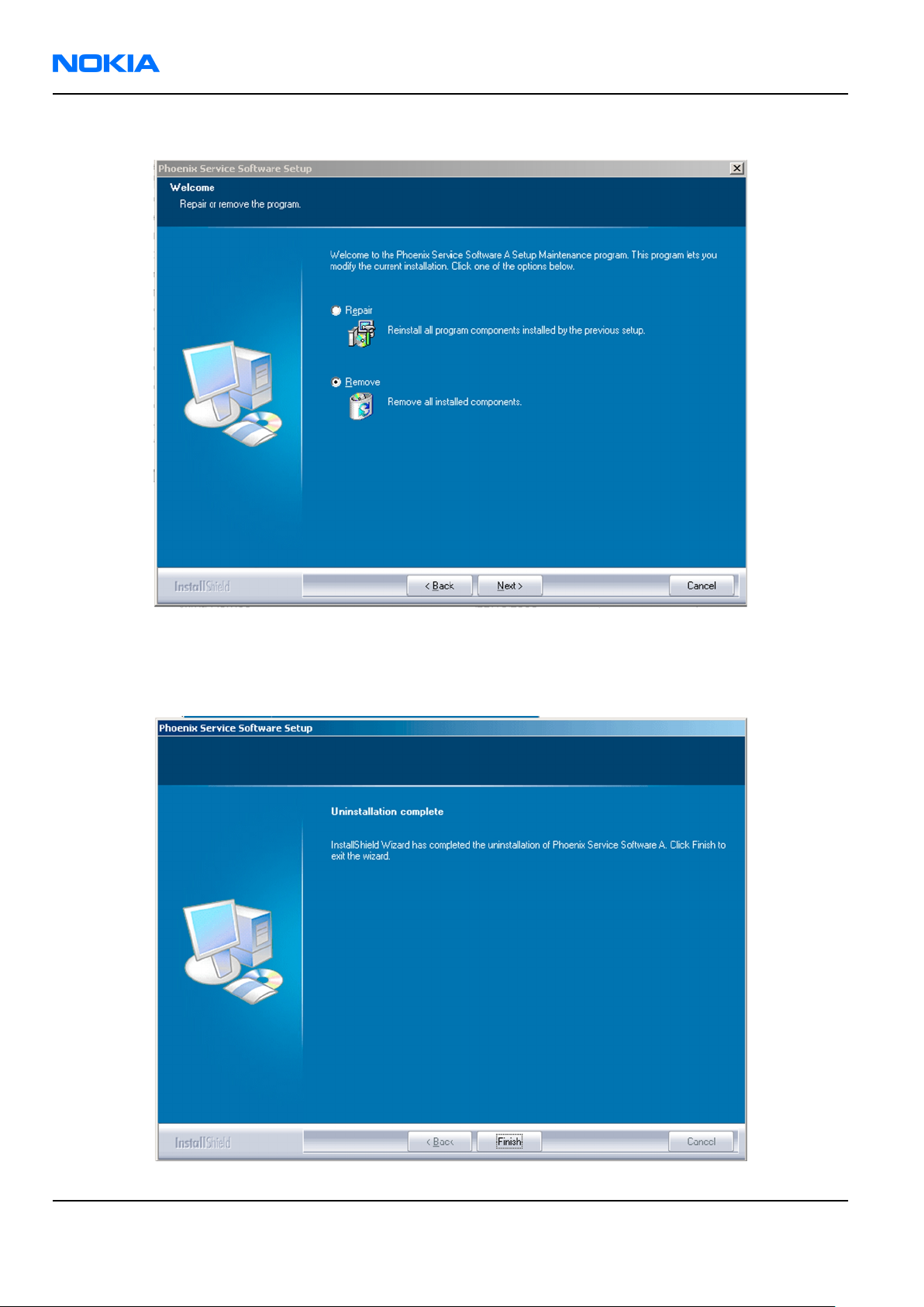
RM-156
Nokia Customer Care Phoenix Service Software Instructions
2. To uninstall
Phoenix
, choose Phoenix Service Software→Change/Remove→Remove .
Figure 12 Remove program
The progress of the uninstallation is shown.
3. If the operating system does not require rebooting, click Finish to complete.
Figure 13 Finish uninstallation
Page 3 –10 COMPANY CONFIDENTIAL Issue 1
Copyright © 2007 Nokia. All rights reserved.
Page 69

RM-156
Phoenix Service Software Instructions Nokia Customer Care
If the operating system requires rebooting, InstallShield Wizard will notify you. Select Yes... to reboot the
PC immediately and No... to reboot the PC manually afterwards.
Repairing
Phoenix
installation
Context
If you experience any problems with the service software or suspect that files have been lost, use the repair
function before completely reinstalling
Note: The original installation package (for example,
must be found on your PC when you run the repair setup.
Phoenix
.
phoenix_service_sw_a15_2004_24_7_55.exe
Steps
1. Open Windows Control Panel→Add/Remove Programs .
2. Choose Phoenix Service Software→Change/Remove .
3. In the following view, select Repair.
)
Figure 14 Repair program
Phoenix
The procedure is the same as when updating
4. To complete the repair, click Finish.
reinstalls components and registers them.
Phoenix
.
Phone data package overview
Each product has its own data package (DP). The product data package contains all product-specific data files
to make the Phoenix service software and tools usable with a certain phone model.
The phone data package contains the following:
• Product software binary files
Issue 1 COMPANY CONFIDENTIAL Page 3 –11
Copyright © 2007 Nokia. All rights reserved.
Page 70

RM-156
Nokia Customer Care Phoenix Service Software Instructions
• Files for type label printing
• Validation file for the fault log repair data reporting system
• All product-specific configuration files for Phoenix software components
Data files are stored in C:\Program Files\Nokia\Phoenix (default).
Installing phone data package
Prerequisites
• A phone-specific data package contains all data required for the
to be used with a certain phone model.
• Check that a dongle is attached to the parallel port of your computer.
• Install
• Download the installation package (for example,
in C:\TEMP).
• Close all other programs.
(XX-XX = type designator of the product)
If you already have
released.
Phoenix
service software.
XX-XX_dp_EA_v_1_0.exe
Phoenix
Note: Often
version of
available versions of both. Instructions can be found in phone-specific Technical Bulletins and
readme.txt
Phoenix
Phoenix
files of data packages.
installed on your computer, you will need to update it when a new version is
and the phone-specific data package come in pairs, meaning that a certain
can only be used with a certain version of a data package. Always use the latest
Phoenix
service software and service tools
) to your computer (for example,
Steps
1. To start the installation, run the application file (for example,
Wait for the installation files to be extracted.
XX-XX_dp_EA_ v_1_0.exe
),
Page 3 –12 COMPANY CONFIDENTIAL Issue 1
Copyright © 2007 Nokia. All rights reserved.
Page 71
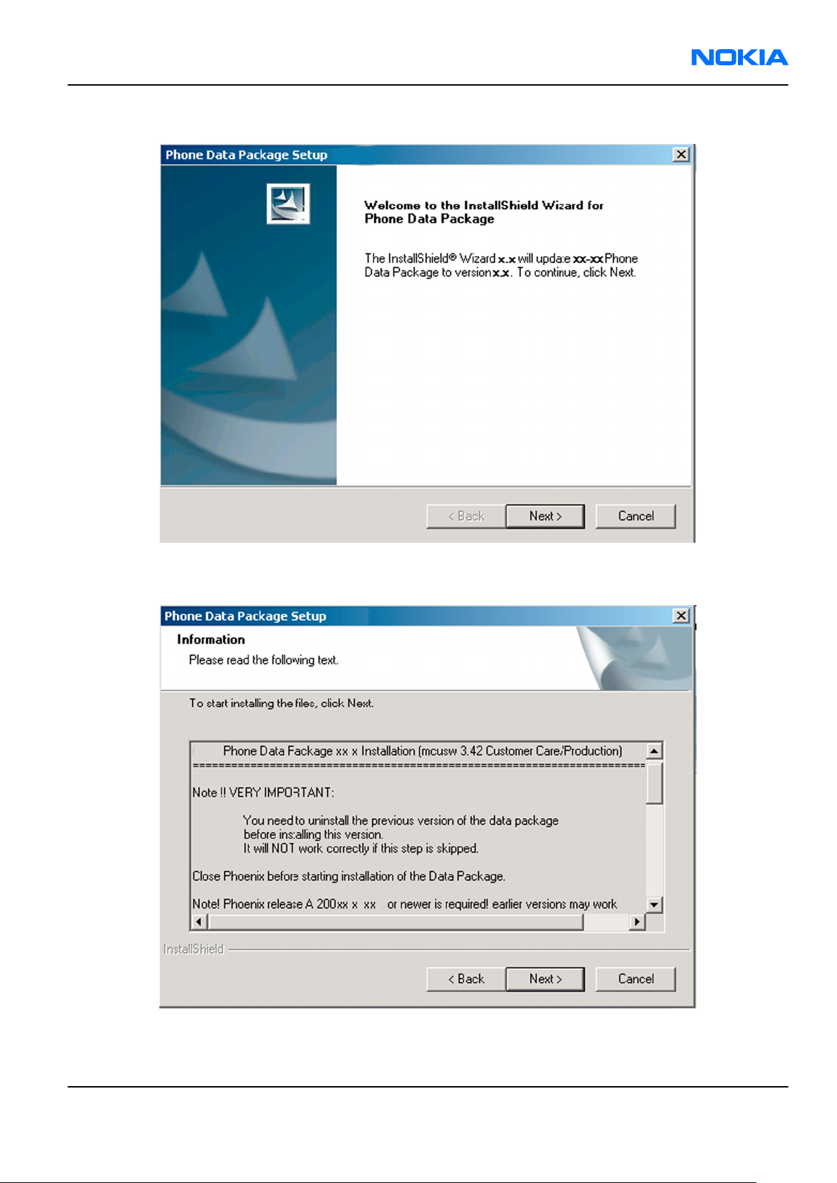
RM-156
Phoenix Service Software Instructions Nokia Customer Care
2. Click Next.
3. In the following view you can see the contents of the data package. Read the text carefully. There is
information about the
Phoenix
version required with this data package.
Figure 15 Data package setup information
4. To continue, click Next.
Issue 1 COMPANY CONFIDENTIAL Page 3 –13
Copyright © 2007 Nokia. All rights reserved.
Page 72

RM-156
Nokia Customer Care Phoenix Service Software Instructions
5. Choose the destination folder, and click Next to continue.
Figure 16 Data package destination folder
The InstallShield Wizard checks where
6. To start copying the files, click Next.
Phoenix
is installed, and the directory is shown.
Page 3 –14 COMPANY CONFIDENTIAL Issue 1
Copyright © 2007 Nokia. All rights reserved.
Page 73

RM-156
Phoenix Service Software Instructions Nokia Customer Care
Phone model specific files are installed. Please wait.
7. To complete the installation, click Finish.
Figure 17 InstallShield Wizard Complete
Next actions
Phoenix
• Configuring users
• Managing connections
FPS-10 can be used after updating their flash update package files.
can be used for flashing phones and printing type labels after:
Uninstalling phone data package
Context
There is no need to uninstall an older version of a data package, unless instructions to do so are given in the
readme.txt
Please read all related documents carefully.
file of the data package and bulletins related to the release.
Steps
1. Locate the data package installation file (e.g.
2. To start the uninstallation procedure, double-click the data package installation file.
XX-XX_dp_EA_v_1_0.exe
) from your computer.
Issue 1 COMPANY CONFIDENTIAL Page 3 –15
Copyright © 2007 Nokia. All rights reserved.
Page 74

RM-156
Nokia Customer Care Phoenix Service Software Instructions
3. To uninstall the data package, click OK or to interrupt the uninstallation, click Cancel.
Figure 18 Uninstalling phone data package
4. When the data package is uninstalled, click Finish.
Figure 19 Finishing data package uninstallation
Alternative steps
• You can also uninstall the data package manually from
Control Panel→Add/Remove Programs→xx-xx* Phone Data Package . (*= type designator of the
phone).
Page 3 –16 COMPANY CONFIDENTIAL Issue 1
Copyright © 2007 Nokia. All rights reserved.
Page 75

RM-156
Phoenix Service Software Instructions Nokia Customer Care
Configuring users in
Phoenix
Steps
1. Start
2. To add a new user, or to edit existing ones, click Maintain.
3. To add a new user, click New.
4. Type in the name and initials of the user, and click OK.
5. Select the desired user from the
Phoenix
If the user ID is already configured, select s/he from the
The user is added to the user name list.
service software, and log in.
Figure 20 Phoenix login
User name
drop-down list, and click OK.
User name
drop-down list, and click OK.
Figure 21 New user configured
Managing connections in
Phoenix
Context
With the Manage Connections feature you can edit and delete existing connections or create new ones.
Note: After choosing the desired connection, and connecting the phone to a PC for the first time,
allow the PC to install the USB device drivers first. Please note that this may take some time to
complete.
If there are problems after the driver installation, check that the USB connection is active from the
Windows Control Panel. If the problem persists, contact the local PC support.
Steps
1. Start
2. Choose File→Manage Connections... .
Issue 1 COMPANY CONFIDENTIAL Page 3 –17
Phoenix
, and log in.
Copyright © 2007 Nokia. All rights reserved.
Page 76

RM-156
Nokia Customer Care Phoenix Service Software Instructions
3. To add a new connection, click Add.
4. Select Manual mode, and click Next to continue.
If you want to create the connection using the Connection Wizard, connect the tools and a phone to your
PC. The wizard will automatically try to configure the correct connection.
Figure 22 Select mode: Manual
i For an FPS-10 flash prommer with a USB Connection, choose the following connection settings:
• Media: FPS-10 USB
• DEVICE_INDEX: 0
• SERIAL_NUM: See Serial No from the label attached to the bottom of FPS-10
• ACTIVE_MEDIA: USB
ii For an FPS-10 flash prommer with a LAN connection, choose the following connection settings:
• Media: FPS-10 TCP/IP
• NET_SERV_NAME: Click Scan.... Choose your own FPS-10 device based on the correct MAC address.
See Serial No from the label attached to the bottom of your FPS-10.
• PORT_NUM: Use the default value, and click Next.
• PROTOCOL_FAMILY: Use the default value, and click Next.
• SOCKET TYPE: Use the default value, and click Next.
• TX_BUFFER_SIZE: Use the default value, and click Next.
• RX_BUFFER_SIZE: Use the default value, and click Next.
iii For a plain USB connection, choose the following connection settings:
Note: First connect the DKU-2 USB cable between the PC USB port and phone.
• Media: USB
5. To complete the configuration, click Finish.
Page 3 –18 COMPANY CONFIDENTIAL Issue 1
Copyright © 2007 Nokia. All rights reserved.
Page 77

RM-156
Phoenix Service Software Instructions Nokia Customer Care
6. Click the connection you want to activate. Use the up/down arrows located on the right hand side to move
it on top of the list, then click Apply.
Figure 23 Connections list
The connection is activated, and it can be used after closing the
The connection information is shown at the right hand bottom corner of the screen.
Figure 24 Connection information
7. To use the connection, connect the phone to your PC with correct service tools. Make sure the phone is
switched on, and then choose File→Scan Product .
Manage Connection
window.
Results
The product support module information appears in the status bar:
Figure 25 Product support module information (example from RM-1)
Installing flash support files for FPS-10
Prerequisites
Note: You need to install flash support files for FPS-10 only, if you don’t have the latest Phoenix
available or the flash support files have changed after the latest Phoenix release.
• Flash support files are installed automatically, when you install Phoenix. Use Phoenix packages later than
June 2006.
• Normally it is enough to install Phoenix and the phone-specific data package because the Phoenix
installation always includes the latest flash update package files for FPS-10.
• A separate installation package for flash support files is available, and the files can be updated according
to this instruction, if updates appear between new Phoenix / data package releases
Context
If you are not using a separate installation package, you can skip this section and continue with "Updating
FPS-10 flash prommer software" (page 3–22) after installing a new phone data package.
Issue 1 COMPANY CONFIDENTIAL Page 3 –19
Copyright © 2007 Nokia. All rights reserved.
Page 78

RM-156
Nokia Customer Care Phoenix Service Software Instructions
Steps
1. To begin installation, double- click
flash_update_x_yy.exe
.
Figure 26 Flash update welcome dialog
If the same version of Flash Update package already exists, and you want to reinstall it, the previous
package is first uninstalled. Restart installation again after that.
2. If you try to downgrade the existing version to older ones, the setup will be aborted. If you really want
to downgrade, uninstall newer files manually from Control Panel and then rerun the installation again.
Figure 27 Flash installation interrupted
If an older version exists on your PC and it needs to be updated, click Next to continue installation.
Page 3 –20 COMPANY CONFIDENTIAL Issue 1
Copyright © 2007 Nokia. All rights reserved.
Page 79

RM-156
Phoenix Service Software Instructions Nokia Customer Care
3. It is highly recommended to install the files to the default destination folder
\Phoenix
. Click Next to continue.
C:\Program Files\Nokia
Figure 28 Flash destination folder
When installing the flash update files for the first time you may choose another location by selecting
Browse. However, this is not recommended.
Issue 1 COMPANY CONFIDENTIAL Page 3 –21
Copyright © 2007 Nokia. All rights reserved.
Page 80

RM-156
Nokia Customer Care Phoenix Service Software Instructions
4. To complete the installation procedure, click Finish .
Figure 29 Finish flash update
Next actions
FPS-10 flash prommers must be updated using Phoenix!
Updating FPS-10 flash prommer software
Steps
1. Start
2. Choose Flashing→Prommer maintenance .
3. When the new flash update package is installed to the computer you will be asked to update the files to
4. Alternatively you can update the FPS-10 flash prommer software by clicking the Update button.
Phoenix Service Software
your Prommer. To update the files, click Yes. Click OK if the computer informs you about an unsafe removal
of the device.
and log in, manage connection correctly for your flash prommer.
Page 3 –22 COMPANY CONFIDENTIAL Issue 1
Copyright © 2007 Nokia. All rights reserved.
Page 81

RM-156
Phoenix Service Software Instructions Nokia Customer Care
5. Wait until you are notified that update has been successful; the procedure will take a couple of minutes.
Click OK to close the
Update Done
window.
Figure 30 Prommer SW update finished
6. If you are using the FPS-10 flash prommer, check that it is detected from the progress info. Check also the
status leds in the FPS-10. The MODE2 led (green), VBAT and POWER leds (red) should be lit. If you are using
LAN connection, the LAN led (yellow) should be blinking.
7. Check that your FPS-10 flash prommer has enough memory. Flashing the SU-18 with FPS-10 needs at least
128 MB of SRAM memory in the prommer.
Figure 31 Prommer maintenance window
Issue 1 COMPANY CONFIDENTIAL Page 3 –23
Copyright © 2007 Nokia. All rights reserved.
Page 82
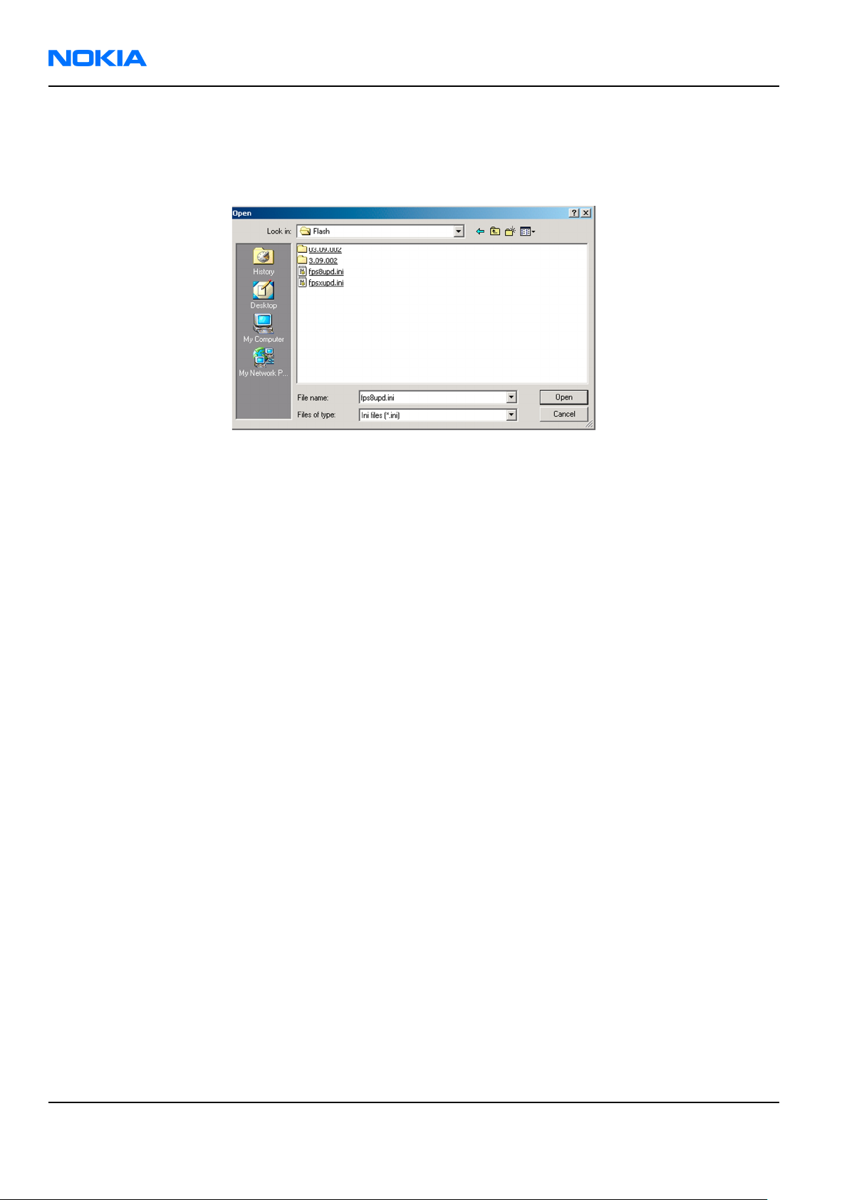
RM-156
Nokia Customer Care Phoenix Service Software Instructions
Alternative steps
• You can update FPS-10 SW by clicking the Update button and selecting the appropriate fpsxupd.ini file in
C:\Program Files\Nokia\Phoenix\Flash
• All files can be loaded separately to the prommer used. To do this, click the right mouse button in the
Flash box files
More information can be found in Phoenix Help.
window and select the file type to be loaded.
.
Figure 32 Flash directory window
Page 3 –24 COMPANY CONFIDENTIAL Issue 1
Copyright © 2007 Nokia. All rights reserved.
Page 83

Nokia Customer Care
4 — Service Tools and Service
Concepts
Issue 1 COMPANY CONFIDENTIAL Page 4 –1
Copyright © 2007 Nokia. All rights reserved.
Page 84

RM-156
Nokia Customer Care Service Tools and Service Concepts
(This page left intentionally blank.)
Page 4 –2 COMPANY CONFIDENTIAL Issue 1
Copyright © 2007 Nokia. All rights reserved.
Page 85

RM-156
Service Tools and Service Concepts Nokia Customer Care
Table of Contents
New service tools ...................................................................................................................................................4–5
FS-22...................................................................................................................................................................4–5
MJ-95...................................................................................................................................................................4–5
RJ-110 .................................................................................................................................................................4–5
SA-118 ................................................................................................................................................................4–6
SS-107.................................................................................................................................................................4–6
General service tools..............................................................................................................................................4–6
CA-31D ................................................................................................................................................................4–6
CA-35S.................................................................................................................................................................4–6
CA-53...................................................................................................................................................................4–6
CA-58RS...............................................................................................................................................................4–7
CA-64U ................................................................................................................................................................4–7
CU-4.....................................................................................................................................................................4–8
DAU-9S................................................................................................................................................................4–9
FPS-10.................................................................................................................................................................4–9
JXS-1....................................................................................................................................................................4–9
PCS-1................................................................................................................................................................ 4–10
PKD-1 ............................................................................................................................................................... 4–10
SB-6.................................................................................................................................................................. 4–10
SB-7.................................................................................................................................................................. 4–10
SRT-6................................................................................................................................................................ 4–11
SS-46................................................................................................................................................................ 4–11
SS-62................................................................................................................................................................ 4–11
SS-93................................................................................................................................................................ 4–11
SX-4.................................................................................................................................................................. 4–11
XCS-4 ................................................................................................................................................................ 4–12
XRS-6................................................................................................................................................................ 4–12
Non-standard service tools ................................................................................................................................ 4–12
PC TV card........................................................................................................................................................ 4–12
Standard TV set............................................................................................................................................... 4–13
Service concepts .................................................................................................................................................. 4–13
POS (Point of Sale) flash concept .................................................................................................................. 4–13
CU-4 flash concept with FPS-10..................................................................................................................... 4–14
Module jig service concept............................................................................................................................ 4–15
RF testing concept with RF coupler .............................................................................................................. 4–16
Service concept for RF testing and RF/BB tuning........................................................................................ 4–17
Flash concept with FPS-10, SS-62 and SB-7 ................................................................................................. 4–18
LAN connection flash concept....................................................................................................................... 4–19
TV-out testing concept .................................................................................................................................. 4–20
List of Figures
Figure 33 POS flash concept ............................................................................................................................... 4–13
Figure 34 CU-4 flash concept with FPS-10......................................................................................................... 4–14
Figure 35 Module jig service concept................................................................................................................ 4–15
Figure 36 RF testing concept with RF coupler.................................................................................................. 4–16
Figure 37 Service concept for RF testing and RF/BB tuning............................................................................ 4–17
Figure 38 Flash concept with FPS-10, SB-7 and JBT-9...................................................................................... 4–18
Issue 1 COMPANY CONFIDENTIAL Page 4 –3
Copyright © 2007 Nokia. All rights reserved.
Page 86

RM-156
Nokia Customer Care Service Tools and Service Concepts
(This page left intentionally blank.)
Page 4 –4 COMPANY CONFIDENTIAL Issue 1
Copyright © 2007 Nokia. All rights reserved.
Page 87

RM-156
Service Tools and Service Concepts Nokia Customer Care
New service tools
The table below gives a short overview of service tools that can be used for testing, error analysis and repair
of product RM-156, refer to various concepts.
FS-22 Flash adapter Flash adapter FS-22 is used for phone testing and flashing.
FS-22 is used with the generic flash adapter base SS-60/62 and control
Unit CU-4 or interface adapter SS-46. When flashing or system testing
the phone, the adapter is attached to replace the phone own battery.
All functions (as well as the calibration voltages, current and the
protections for over voltages, over current and voltage polarity), are
performed by CU-4.
Flash adapter FS-22 main features:
• VBATT supply interface
• USB / FBUS multiplexed interface to the phone
• Supply voltage for light source
MJ-95 Module jig
MJ-95 is meant for component level troubleshooting.
The jig includes an RF interface for GSM, WCDMA, Bluetooth and WLAN.
In addition, it has the following features:
• Provides mechanical interface with the engine module
• Provides galvanic connection to all needed test pads in module
• Multiplexing between USB and FBUS media, controlled by Vusb
• UI test interface
• SD interface
• Duplicated SIM connector
• Audio components: IHF, MIC, earpiece
• Connector for control unit
•
Access for Pop-PortTM system connector
RJ-110 Rework jig RJ-110 is a rework jig used with ST-43.
Issue 1 COMPANY CONFIDENTIAL Page 4 –5
Copyright © 2007 Nokia. All rights reserved.
Page 88

RM-156
Nokia Customer Care Service Tools and Service Concepts
SA-118 RF coupler SA-118 is used for RF testing with FS-22, SS-62 and CU-4.
SS-107 Window removal
tool
SS-107 is used for removing sub LCD window assy without
disassembling the phone.
General service tools
The table below gives a short overview of service tools that can be used for testing, error analysis and repair
of product RM-156, refer to various concepts.
CA-31D USB cable The CA-31D USB cable is used to connect FPS-10 or FPS-11 to a PC. It is
included in the FPS-10 and FPS-11 sales packages.
CA-35S Power cable
CA-35S is a power cable for connecting, for example, the FPS-10 flash
prommer to the Point-Of-Sales (POS) flash adapter.
CA-53 USB connectivity
cable
USB to system connector cable.
Page 4 –6 COMPANY CONFIDENTIAL Issue 1
Copyright © 2007 Nokia. All rights reserved.
Page 89

RM-156
Service Tools and Service Concepts Nokia Customer Care
CA-58RS RF tuning cable RF tuning cable for use with a flash adapter.
CA-58RS RF cable extends adapter features to allow RF function tests
and RF tuning in GSM bands.
Features include:
• easy to use together with flash adapter or even stand alone
• most accurate RF connection to phone module under test
• most accurate RF connection to phone module under test
• low attenuation and small “ripple” over the width of each GSM band
Note: The RF cable must be used for RF tuning.
CA-64U Video-out cable CA-64U is used to check TV-out functionality.
Issue 1 COMPANY CONFIDENTIAL Page 4 –7
Copyright © 2007 Nokia. All rights reserved.
Page 90

RM-156
Nokia Customer Care Service Tools and Service Concepts
CU-4 Control unit CU-4 is a general service tool used with a module jig and/or a flash
adapter. It requires an external 12 V power supply.
The unit has the following features:
• software controlled via USB
• EM calibration function
• Forwards FBUS/Flashbus traffic to/from terminal
• Forwards USB traffic to/from terminal
• software controlled BSI values
• regulated VBATT voltage
• 2 x USB2.0 connector (Hub)
• FBUS and USB connections supported
When using CU-4, note the special order of connecting cables and
other service equipment:
Instructions
1 Connect a service tool (jig, flash adapter) to CU-4.
2 Connect CU-4 to your PC with a USB cable.
3 Connect supply voltage (12 V)
4 Connect an FBUS cable (if necessary).
5 Start Phoenix service software.
Note: Phoenix enables CU-4 regulators via USB when it is
started.
Reconnecting the power supply requires a Phoenix restart.
Page 4 –8 COMPANY CONFIDENTIAL Issue 1
Copyright © 2007 Nokia. All rights reserved.
Page 91

RM-156
Service Tools and Service Concepts Nokia Customer Care
DAU-9S MBUS cable The MBUS cable DAU-9S has a modular connector and is used, for
example, between the PC's serial port and module jigs, flash adapters
or docking station adapters.
Note: Docking station adapters valid for DCT4 products.
FPS-10 Flash prommer FPS-10 interfaces with:
• PC
• Control unit
• Flash adapter
• Smart card
FPS-10 flash prommer features:
• Flash functionality for BB5 and DCT-4 terminals
• Smart Card reader for SX-2 or SX-4
• USB traffic forwarding
• USB to FBUS/Flashbus conversion
• LAN to FBUS/Flashbus and USB conversion
• Vusb output switchable by PC command
FPS-10 sales package includes:
• FPS-10 prommer
• Power Supply with 5 country specific cords
• USB cable
JXS-1 RF shield box
Because the WCDMA network disturbs the RX side testing of the WCDMA
phone and the Tx signal of the WCDMA phone can severely disturb the
WCDMA network, a shield box is needed in all testing, tuning and fault
finding which requires WCDMA RF signal.
The shield box is not an active device, it contains only passive filtering
components for RF attenuation.
Issue 1 COMPANY CONFIDENTIAL Page 4 –9
Copyright © 2007 Nokia. All rights reserved.
Page 92

RM-156
Nokia Customer Care Service Tools and Service Concepts
PCS-1 Power cable The PCS-1 power cable (DC) is used with a docking station, a module
jig or a control unit to supply a controlled operating voltage.
PKD-1 SW security device SW security device is a piece of hardware enabling the use of the
service software when connected to the parallel (LPT) port of the PC.
Without the device, it is not possible to use the service software.
Printer or any such device can be connected to the PC through the
device if needed.
SB-6 Bluetooth tester The SB-6 test box is a generic device to perform Bluetooth bit error
rate testing and doing cordless FBUS connection via Bluetooth.
SB-7 WLAN test box WLAN test requires defined position for the device.
Page 4 –10 COMPANY CONFIDENTIAL Issue 1
Copyright © 2007 Nokia. All rights reserved.
Page 93

RM-156
Service Tools and Service Concepts Nokia Customer Care
SRT-6 Opening tool SRT-6 is used to open phone covers and B-to-B connectors.
SS-46 Interface adapter SS-46 acts as an interface adapter between the flash adapter and
FPS-10.
SS-62 Generic flash adapter
base for BB5
• generic base for flash adapters and couplers
• SS-62 equipped with a clip interlock system
• provides standardised interface towards Control Unit
• provides RF connection using galvanic connector or coupler
• multiplexing between USB and FBUS media, controlled by VUSB
SS-93 Opening tool SS-93 is used for opening JAE connectors.
SX-4 Smart card SX-4 is a BB5 security device used to protect critical features in tuning
and testing.
SX-4 is also needed together with FPS-10 when DCT-4 phones are
flashed.
Issue 1 COMPANY CONFIDENTIAL Page 4 –11
Copyright © 2007 Nokia. All rights reserved.
Page 94

RM-156
Nokia Customer Care Service Tools and Service Concepts
XCS-4 Modular cable XCS-4 is a shielded (one specially shielded conductor) modular cable
for flashing and service purposes.
XRS-6 RF cable The RF cable is used to connect, for example, a module repair jig to
the RF measurement equipment.
SMA to N-Connector approximately 610 mm.
Attenuation for:
• GSM850/900: 0.3+-0.1 dB
• GSM1800/1900: 0.5+-0.1 dB
• WLAN: 0.6+-0.1dB
Non-standard service tools
The table below gives a short overview of service tools that can be used for testing, error analysis and repair
of product RM-156, refer to various concepts.
PC TV card
A PC TV card can be used for testing the TV-out functionality. The
minimum requirements for a TV card are the following:
• Video formats:
• NTSC and PAL input support
• Physical inputs:
• female inputs
• composite video input
• RCA Audio input or an input adaptable to RCA using a converter
cable (e.g. 3.5 mm input)
Different devices are available from various vendors, and can be used
without special approval from Nokia.
Page 4 –12 COMPANY CONFIDENTIAL Issue 1
Copyright © 2007 Nokia. All rights reserved.
Page 95

RM-156
Service Tools and Service Concepts Nokia Customer Care
Standard TV set
A standard TV set is used for testing the TV-out functionality of the
device. A commercial colour TV set with compatible video formats
(NTSC or PAL) can be used in service centers.
Different devices are available from various vendors, and can be used
without special approval from Nokia.
Service concepts
POS (Point of Sale) flash concept
Figure 33 POS flash concept
Type Description
Product specific tools
BL-5F Battery
Other tools
FLS-4S POS flash dongle
PC with Phoenix service software
Issue 1 COMPANY CONFIDENTIAL Page 4 –13
Copyright © 2007 Nokia. All rights reserved.
Page 96

RM-156
Nokia Customer Care Service Tools and Service Concepts
Type Description
Cables
CA-53 USB connectivity cable
CU-4 flash concept with FPS-10
Figure 34 CU-4 flash concept with FPS-10
Type Description
Product specific tools
FS-22 Flash adapter
Other tools
CU-4 Control unit
FPS-10 Flash prommer box
PKD-1/PK-1 SW security device
SS-62 Flash adapter base
SX-4 Smart card
PC with Phoenix service software
Cables
PCS-1 Power cable
XCS-4 Modular cable
Page 4 –14 COMPANY CONFIDENTIAL Issue 1
Copyright © 2007 Nokia. All rights reserved.
Page 97

RM-156
Service Tools and Service Concepts Nokia Customer Care
Type Description
Standard USB cable
USB cable
Module jig service concept
Figure 35 Module jig service concept
Type Description
Phone specific tools
MJ-95 Module jig
Other tools
CU-4 Control unit
FPS-10 Flash prommer box
PKD-1/PK-1 SW security device
SX-4 Smart card
PC with Phoenix service software
Measurement equipment
Cables
PCS-1 DC power cable
Issue 1 COMPANY CONFIDENTIAL Page 4 –15
Copyright © 2007 Nokia. All rights reserved.
Page 98

RM-156
Nokia Customer Care Service Tools and Service Concepts
Type Description
XCS-4 Modular cable
XRS-6 RF cable
USB cable
GPIB control cable
RF testing concept with RF coupler
Figure 36 RF testing concept with RF coupler
Type Description
Product specific tools
FS-22 Flash adapter
SA-118 RF coupler
Other tools
CU-4 Control unit
SX-4 Smart card
FPS-10 Flash prommer box
PKD-1/PK-1 SW security device
SS-62 Flash adapter base
Measurement equipment
Page 4 –16 COMPANY CONFIDENTIAL Issue 1
Copyright © 2007 Nokia. All rights reserved.
Page 99

RM-156
Service Tools and Service Concepts Nokia Customer Care
Type Description
PC with Phoenix service software
Cables
PCS-1 Power cable
XCS-4 Modular cable
XRS-6 RF cable
GPIB control cable
USB cable
Service concept for RF testing and RF/BB tuning
Figure 37 Service concept for RF testing and RF/BB tuning
Type Description
Product specific tools
MJ-95 Module jig
Other tools
CU-4 Control unit
SX-4 Smart card
Measurement equipment
Issue 1 COMPANY CONFIDENTIAL Page 4 –17
Copyright © 2007 Nokia. All rights reserved.
Page 100

RM-156
Nokia Customer Care Service Tools and Service Concepts
Type Description
Smart card reader
PC with Phoenix service software
Cables
DAU-9s MBUS cable
PCS-1 DC power cable
PKD-1/PK-1 SW security device
XRS-6 RF cable
GPIB control cable
USB cable
Flash concept with FPS-10, SS-62 and SB-7
Figure 38 Flash concept with FPS-10, SB-7 and JBT-9
Type Description
Product specific tools
FS-22 Flash adapter
Other tools
CU-4 Control unit
FPS-10 Flash prommer box
Page 4 –18 COMPANY CONFIDENTIAL Issue 1
Copyright © 2007 Nokia. All rights reserved.
 Loading...