

Page 1

Nokia Customer Care
Service Manual
RM-100 (Nokia N92)
Mobile Terminal
Part No: 9252561 (Issue 2)
COMPANY CONFIDENTIAL
Copyright © 2007 Nokia. All rights reserved.
Page 2
RM-100
Nokia Customer Care Amendment Record Sheet
Amendment Record Sheet
Amendment No Date Inserted By Comments
Issue 1 08/2006 Phil Harvey
Issue 2 01/2007 Tiina Saven Updates for parts, schematics, TV
troubleshooting and service tools
sections.
Page ii COMPANY CONFIDENTIAL Issue 2
Copyright © 2007 Nokia. All rights reserved.
Page 3

RM-100
Copyright Nokia Customer Care
Copyright
Copyright © 2007 Nokia. All rights reserved.
Reproduction, transfer, distribution or storage of part or all of the contents in this document in any form
without the prior written permission of Nokia is prohibited.
Nokia, Nokia Connecting People, and Nokia X and Y are trademarks or registered trademarks of Nokia
Corporation. Other product and company names mentioned herein may be trademarks or tradenames of
their respective owners.
Nokia operates a policy of continuous development. Nokia reserves the right to make changes and
improvements to any of the products described in this document without prior notice.
Under no circumstances shall Nokia be responsible for any loss of data or income or any special, incidental,
consequential or indirect damages howsoever caused.
The contents of this document are provided "as is". Except as required by applicable law, no warranties of
any kind, either express or implied, including, but not limited to, the implied warranties of merchantability
and fitness for a particular purpose, are made in relation to the accuracy, reliability or contents of this
document. Nokia reserves the right to revise this document or withdraw it at any time without prior notice.
The availability of particular products may vary by region.
IMPORTANT
This document is intended for use by qualified service personnel only.
Issue 2 COMPANY CONFIDENTIAL Page iii
Copyright © 2007 Nokia. All rights reserved.
Page 4

RM-100
Nokia Customer Care Warnings and cautions
Warnings and cautions
Warnings
• IF THE DEVICE CAN BE INSTALLED IN A VEHICLE, CARE MUST BE TAKEN ON INSTALLATION IN VEHICLES FITTED
WITH ELECTRONIC ENGINE MANAGEMENT SYSTEMS AND ANTI-SKID BRAKING SYSTEMS. UNDER CERTAIN FAULT
CONDITIONS, EMITTED RF ENERGY CAN AFFECT THEIR OPERATION. IF NECESSARY, CONSULT THE VEHICLE DEALER/
MANUFACTURER TO DETERMINE THE IMMUNITY OF VEHICLE ELECTRONIC SYSTEMS TO RF ENERGY.
• THE PRODUCT MUST NOT BE OPERATED IN AREAS LIKELY TO CONTAIN POTENTIALLY EXPLOSIVE ATMOSPHERES,
FOR EXAMPLE, PETROL STATIONS (SERVICE STATIONS), BLASTING AREAS ETC.
• OPERATION OF ANY RADIO TRANSMITTING EQUIPMENT, INCLUDING CELLULAR TELEPHONES, MAY INTERFERE
WITH THE FUNCTIONALITY OF INADEQUATELY PROTECTED MEDICAL DEVICES. CONSULT A PHYSICIAN OR THE
MANUFACTURER OF THE MEDICAL DEVICE IF YOU HAVE ANY QUESTIONS. OTHER ELECTRONIC EQUIPMENT MAY
ALSO BE SUBJECT TO INTERFERENCE.
• BEFORE MAKING ANY TEST CONNECTIONS, MAKE SURE YOU HAVE SWITCHED OFF ALL EQUIPMENT.
Cautions
• Servicing and alignment must be undertaken by qualified personnel only.
• Ensure all work is carried out at an anti-static workstation and that an anti-static wrist strap is worn.
• Ensure solder, wire, or foreign matter does not enter the telephone as damage may result.
• Use only approved components as specified in the parts list.
• Ensure all components, modules, screws and insulators are correctly re-fitted after servicing and
alignment.
• Ensure all cables and wires are repositioned correctly.
• Never test a mobile phone WCDMA transmitter with full Tx power, if there is no possibility to perform the
measurements in a good performance RF-shielded room. Even low power WCDMA transmitters may disturb
nearby WCDMA networks and cause problems to 3G cellular phone communication in a wide area.
• During testing never activate the GSM or WCDMA transmitter without a proper antenna load, otherwise
GSM or WCDMA PA may be damaged.
Page iv COMPANY CONFIDENTIAL Issue 2
Copyright © 2007 Nokia. All rights reserved.
Page 5

RM-100
ESD protection Nokia Customer Care
ESD protection
Nokia requires that service points have sufficient ESD protection (against static electricity) when servicing
the phone.
Any product of which the covers are removed must be handled with ESD protection. The SIM card can be
replaced without ESD protection if the product is otherwise ready for use.
To replace the covers ESD protection must be applied.
All electronic parts of the product are susceptible to ESD. Resistors, too, can be damaged by static electricity
discharge.
All ESD sensitive parts must be packed in metallized protective bags during shipping and handling outside
any ESD Protected Area (EPA).
Every repair action involving opening the product or handling the product components must be done under
ESD protection.
ESD protected spare part packages MUST NOT be opened/closed out of an ESD Protected Area.
For more information and local requirements about ESD protection and ESD Protected Area, contact your local
Nokia After Market Services representative.
Issue 2 COMPANY CONFIDENTIAL Page v
Copyright © 2007 Nokia. All rights reserved.
Page 6

RM-100
Nokia Customer Care Care and maintenance
Care and maintenance
This product is of superior design and craftsmanship and should be treated with care. The suggestions below
will help you to fulfil any warranty obligations and to enjoy this product for many years.
• Keep the phone and all its parts and accessories out of the reach of small children.
• Keep the phone dry. Precipitation, humidity and all types of liquids or moisture can contain minerals that
will corrode electronic circuits.
• Do not use or store the phone in dusty, dirty areas. Its moving parts can be damaged.
• Do not store the phone in hot areas. High temperatures can shorten the life of electronic devices, damage
batteries, and warp or melt certain plastics.
• Do not store the phone in cold areas. When it warms up (to its normal temperature), moisture can form
inside, which may damage electronic circuit boards.
• Do not drop, knock or shake the phone. Rough handling can break internal circuit boards.
• Do not use harsh chemicals, cleaning solvents, or strong detergents to clean the phone.
• Do not paint the phone. Paint can clog the moving parts and prevent proper operation.
• Use only the supplied or an approved replacement antenna. Unauthorised antennas, modifications or
attachments could damage the phone and may violate regulations governing radio devices.
All of the above suggestions apply equally to the product, battery, charger or any accessory.
Page vi COMPANY CONFIDENTIAL Issue 2
Copyright © 2007 Nokia. All rights reserved.
Page 7

RM-100
Company Policy Nokia Customer Care
Company Policy
Our policy is of continuous development; details of all technical modifications will be included with service
bulletins.
While every endeavour has been made to ensure the accuracy of this document, some errors may exist. If
any errors are found by the reader, NOKIA MOBILE PHONES Business Group should be notified in writing/email.
Please state:
• Title of the Document + Issue Number/Date of publication
• Latest Amendment Number (if applicable)
• Page(s) and/or Figure(s) in error
Please send to:
NOKIA CORPORATION
Nokia Mobile Phones Business Group
Nokia Customer Care
PO Box 86
FIN-24101 SALO
Finland
E-mail: Service.Manuals@nokia.com
Issue 2 COMPANY CONFIDENTIAL Page vii
Copyright © 2007 Nokia. All rights reserved.
Page 8

RM-100
Nokia Customer Care Battery information
Battery information
Note: A new battery's full performance is achieved only after two or three complete charge and
discharge cycles!
The battery can be charged and discharged hundreds of times but it will eventually wear out. When the
operating time (talk-time and standby time) is noticeably shorter than normal, it is time to buy a new battery.
Use only batteries approved by the phone manufacturer and recharge the battery only with the chargers
approved by the manufacturer. Unplug the charger when not in use. Do not leave the battery connected to
a charger for longer than a week, since overcharging may shorten its lifetime. If left unused a fully charged
battery will discharge itself over time.
Temperature extremes can affect the ability of your battery to charge.
For good operation times with Ni-Cd/NiMh batteries, discharge the battery from time to time by leaving the
product switched on until it turns itself off (or by using the battery discharge facility of any approved accessory
available for the product). Do not attempt to discharge the battery by any other means.
Use the battery only for its intended purpose.
Never use any charger or battery which is damaged.
Do not short-circuit the battery. Accidental short-circuiting can occur when a metallic object (coin, clip or
pen) causes direct connection of the + and - terminals of the battery (metal strips on the battery) for example
when you carry a spare battery in your pocket or purse. Short-circuiting the terminals may damage the battery
or the connecting object.
Leaving the battery in hot or cold places, such as in a closed car in summer or winter conditions, will reduce
the capacity and lifetime of the battery. Always try to keep the battery between 15°C and 25°C (59°F and 77°
F). A phone with a hot or cold battery may temporarily not work, even when the battery is fully charged.
Batteries' performance is particularly limited in temperatures well below freezing.
Do not dispose of batteries in a fire!
Dispose of batteries according to local regulations (e.g. recycling). Do not dispose as household waste.
Page viii COMPANY CONFIDENTIAL Issue 2
Copyright © 2007 Nokia. All rights reserved.
Page 9

RM-100
Nokia N92 Service Manual Structure Nokia Customer Care
Nokia N92 Service Manual Structure
1 General Information
2 Parts Lists and Component Layouts
3 Service Software Instructions
4 Service Tools and Service Concepts
5 Disassembly/Reassembly Instructions
6 BB Troubleshooting and Manual Tuning Guide
7 RF Troubleshooting and Manual Tuning Guide
8 Camera Module Troubleshooting
9 TV troubleshooting
10 System Module
11 Schematics
Glossary
Issue 2 COMPANY CONFIDENTIAL Page ix
Copyright © 2007 Nokia. All rights reserved.
Page 10

RM-100
Nokia Customer Care Nokia N92 Service Manual Structure
(This page left intentionally blank.)
Page x COMPANY CONFIDENTIAL Issue 2
Copyright © 2007 Nokia. All rights reserved.
Page 11
Nokia Customer Care
1 — General Information
Issue 2 COMPANY CONFIDENTIAL Page 1 –1
Copyright © 2007 Nokia. All rights reserved.
Page 12

RM-100
Nokia Customer Care General Information
(This page left intentionally blank.)
Page 1 –2 COMPANY CONFIDENTIAL Issue 2
Copyright © 2007 Nokia. All rights reserved.
Page 13

RM-100
General Information Nokia Customer Care
Table of Contents
RM-100 product selection......................................................................................................................................1–5
RM-100 product features and sales package.......................................................................................................1–5
Product and module list ........................................................................................................................................1–7
Mobile enhancements............................................................................................................................................1–7
Technical specifications.........................................................................................................................................1–9
Transceiver general specifications ..................................................................................................................1–9
Main RF characteristics for triple-band (EGSM900/GSM1800/GSM1900) and WCDMA phones ...................1–9
Battery endurance.......................................................................................................................................... 1–10
Environmental conditions ............................................................................................................................. 1–10
List of Tables
Table 1 Audio..........................................................................................................................................................1–7
Table 2 Car...............................................................................................................................................................1–8
Table 3 Covers.........................................................................................................................................................1–8
Table 4 Data ............................................................................................................................................................1–8
Table 5 Messaging..................................................................................................................................................1–8
Table 6 Power.........................................................................................................................................................1–9
List of Figures
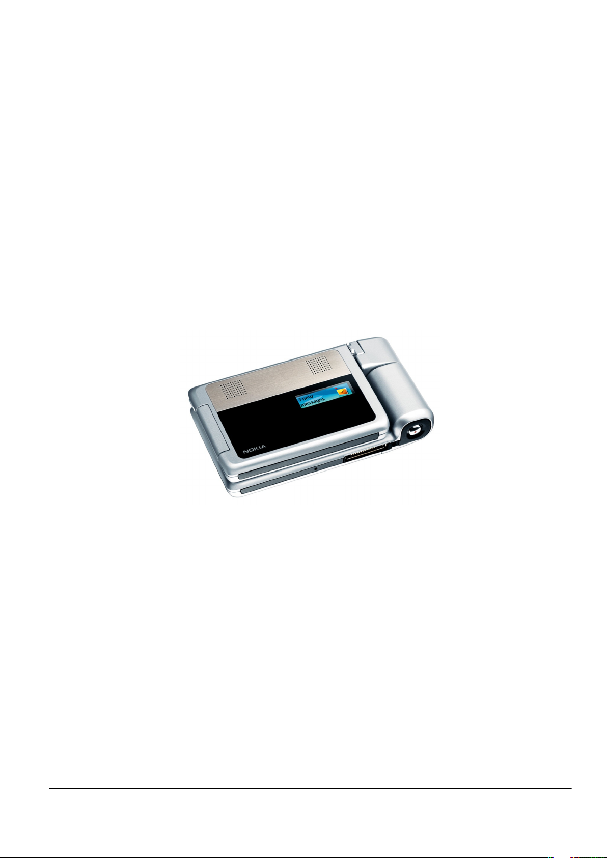
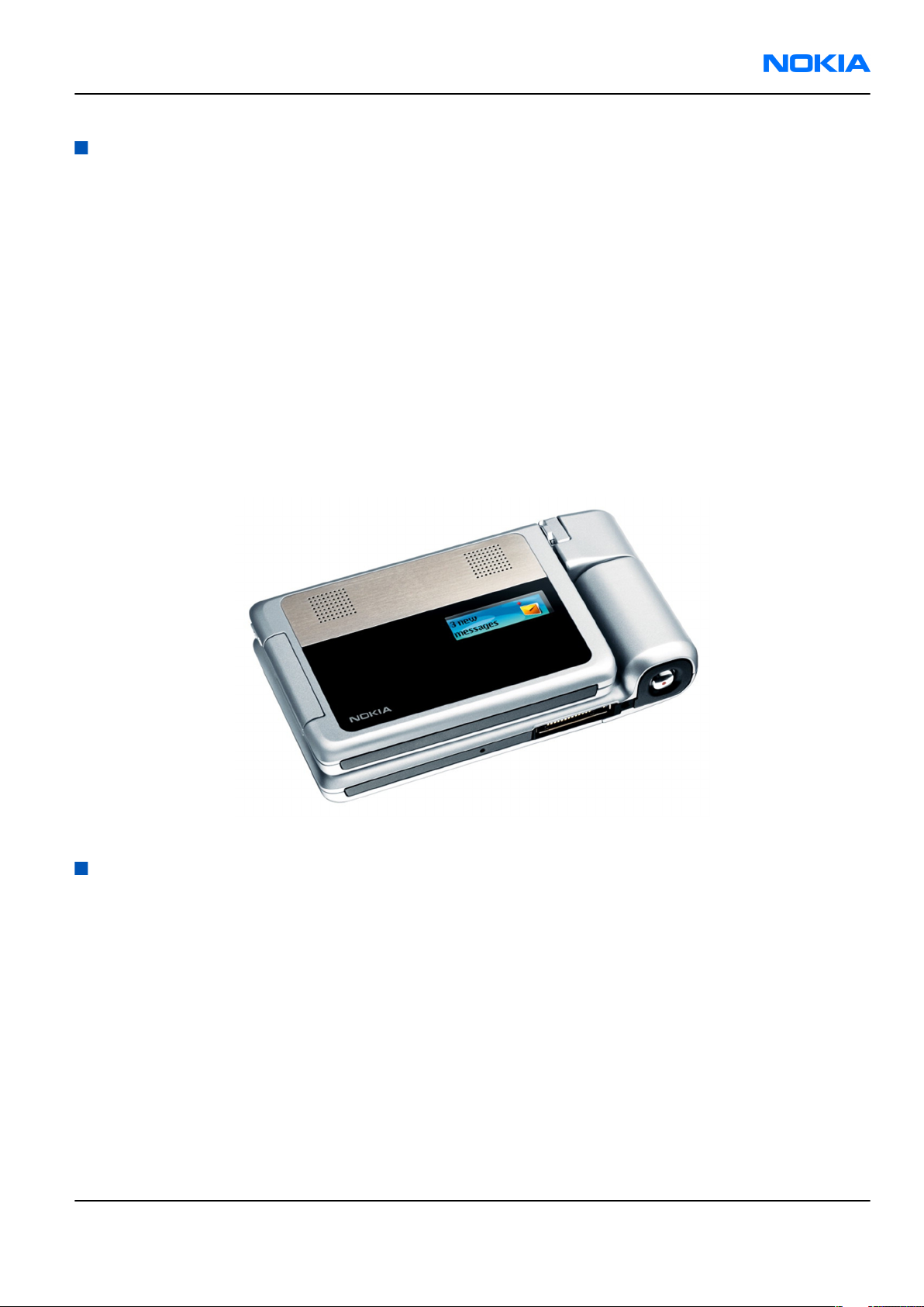
Figure 1 View of RM-100........................................................................................................................................1–5
Issue 2 COMPANY CONFIDENTIAL Page 1 –3
Copyright © 2007 Nokia. All rights reserved.
Page 14

RM-100
Nokia Customer Care General Information
(This page left intentionally blank.)
Page 1 –4 COMPANY CONFIDENTIAL Issue 2
Copyright © 2007 Nokia. All rights reserved.
Page 15
RM-100
General Information Nokia Customer Care
RM-100 product selection
Nokia RM-100 is a WCDMA/GSM dual mode handportable phone that supports GSM (E-GSM900, GSM1800 &
GSM900) and WCDMA2100.
According to GSM standard 05.05 it responds to class 4 (max. 2W) in EGSM 900, class 1 (1W) in GSM 1800 and
class 1 in GSM 1900. RM-100 supports EGPRS (EDGE) class B as well as Bluetooth specification 1.2/2.0/2.0+EDR.
The handset has a full phase 2 Type Approval and it complies with the GSM Type Approval. RM-100 also has
a full CE approval and FCC approval.
RM-100 supports two-way video calls with two integrated cameras. It is an MMS (Multimedia Messaging
Service) enabled phone with a large bright color display and an integrated 2.0 megapixel (effective image
size 1.92 megapixels) digital camera, and a second CIF digital camera.
The MMS implementation follows the OMA MMS standard release 1.2.
WAP 2.0 compatible browser supports XHTML Mobile Profile (MP) and uses a TCP/IP stack to communicate
with a gateway in network.
RM-100 uses Symbian OS 9.1 operating system and supports also MIDP Java 2.0 & CLDC1.1, providing a good
platform for 3rd party applications.
Figure 1 View of RM-100
RM-100 product features and sales package
Display and keypad features
• Active matrix colour 2.8" QVGA main display (320x240, up to 16M colours) and 2nd display 1,1" (128x36
pixel, up to 65,536 colours)
• 4 media keys: play/pause, stop, next and previous.
• 5-way navikey, two softkeys, application-key, clear key, send & end key, ~(operator) service key and
multimedia key.
• ITU-T keypad.
• Side volume keys (volume control and mute).
Key features
• Stylish twist ~& fold phone with metal decos
Issue 2 COMPANY CONFIDENTIAL Page 1 –5
Copyright © 2007 Nokia. All rights reserved.
Page 16

RM-100
Nokia Customer Care General Information
• WCDMW/GSM dual mode handportable device supporting EGSM900/1800/1900 and WCDMA 2100 with
internal antennas
• WCDMA 2100 with simultaneous voice and packet data (PS max speed UL/DL= 384/384kbps, CS max speed
64kpbs)
• Dual Transfer Mode (DTM) class 11 in GSM networks to support simultaneous voice and packet data
• Integrated DVB-H video/audio codecs: H.264 AVC 384kbps at QVGA 15fps/QCIF 30fps and AAC up to 128bps
• EGPRS, class B, multislot class 32, (5 Rx + 3 Tx/max sum 6), max speed DL/UL = 296/177.6 kbits/s
• GPRS, class B, multislot class 32 is also supported with (5 Rx + 3 Tx/max sum 6), max speed DL/UL = 107/64.2
kbits/s
• Speech codecs: FR, EFR, WCDMA and GSM AMR
• Audio codecs: AAC, AAC+, AMR, AMR-NB, AMR-WB, AU, eAAC+, MIDI, MP3, Nokia ring tones, Real Audio 7/8/10,
WAV and WMA
• Integrated 2.0 megapixel (1600 x 1200) camera with up to 4x digital zoom for video/still pictures
• Integrated Flash LED (operating range 1,5 m)
• Privacy indicator LED
• Integrated CIF camera with 2 x digital zoom
• Up to 40 MB internal memory for user data and mini SD card reader (hotswap)
• Bluetooth connectivity, IrDA, and USB 2.0 full speed
• Integrated WLAN (802.11b/g) & UPnP
• Integrated stereo handsfree speaker
• XHTML internet browser-open source
• Integrated FM Stereo radio
• Off-line mode/SIMless mode
• Java™ MIDP 2.0, CLDC 1.1
• Real time clock
Imaging
• Two-way video call
• Advanced camera modes: still/burst/video, night, image quality, self timer, white balance settings and
colour tones
• Flash LED modes: On, Off, Automatic
• Bluetooth Imaging Profile (BIP) and Pictbridge
• Improved multimedia gallery
• Still image editor, image printing, Nokia Lifeblog and image show
Productivity
• SMS, MMS and email
• Office document viewers (Word, Powerpoint, Excel)
• PC Suite connectivity with USB, Bluetooth, IrDA
• Advanced S60 PIM (calendar, contacts, task list, etc.)
• Multimedia player (Real Player) with 3GPP video streaming support
• Voice recording, dialling and voice commands
Page 1 –6 COMPANY CONFIDENTIAL Issue 2
Copyright © 2007 Nokia. All rights reserved.
Page 17
RM-100
General Information Nokia Customer Care
• Access point confiqurator and settings Wizard 2.0
• Start up wizard for easy configuration
• Data Transfer (from S60 phone to S60 phone)
Mobile TV features
• Dedicated mobile TV application for selection, purchase, consumption and storage of TV programs
• Record & Playback and Replay of TV programs
• Mobile TV interactive services
• DVB-H based mobile TV with internal antenna
• Mobile TV video/audio codecs: H264 ACV/AAC
• Channel and content protection: OMA DRM 2.0, IPsec
Sales package
• Transceiver RM-100
• BP-5L Li-Polymer Battery Cell
• AC-4 Charger
• All-in-one User Guide (warranty card + accessory info + getting started sheet + invitational module for Club
Nokia )
• CD-ROM (with PC-Suite)
• Stereo Headset HS-23
• USB Cable CA-53
• Mini SD and miniSD adapter
Product and module list
Module name Type code Notes
System/RF Module RM100: 1NT Main PWB with components,
keyboard
Top module RM100: 1PH DVB-H engine, mini SD reader
Bottom module flex 1QX Flash LED & volume keys
Top module flex 1QY Power switch & earpiece
Mobile enhancements
Table 1 Audio
Enhancement Type
Fashion stereo headset HS-3, HS-31
Classic stereo headset HS-23
Stereo headset HS-20 + AD-41
Activity headset HS-8
Wireless clip-on headset HS-21W
Wireless boom headset HS-4W
Issue 2 COMPANY CONFIDENTIAL Page 1 –7
Copyright © 2007 Nokia. All rights reserved.
Page 18

RM-100
Nokia Customer Care General Information
Enhancement Type
Inductive loopset LPS-4
Wireless headsets HDW-3, HS-11W, HS-26W, HS-36W, &
HS-37W
Bluetooth headset BH-200 HS-58W
Bluetooth headset BH-800 HS-24W
Bluetooth headset BH-900 HS-25W
Audio adapter AD-15, AD-46
Music stand MD-1
Table 2 Car
Enhancement Type
Mobile charger DC-4
Plug-in car handsfree HF-3
Advanced car kits CK-7W
Wireless car kit CK-1W
Plug-in wireless car handsfree HF-6W
Car kit phone N616
Table 3 Covers
Enhancement Type
Non-changeable covers
Table 4 Data
Enhancement Type
Connectivity cable CA-53
Wireless GPS module LD-1W, LD-3W
MiniSD memory card 128MB MU-17
MiniSD memory card 256MB MU-18
MiniSD memory card 512MB MU-23
MiniSD memory card 1GB MU-24
Table 5 Messaging
Enhancement Type
Digital pen SU-1B
Page 1 –8 COMPANY CONFIDENTIAL Issue 2
Copyright © 2007 Nokia. All rights reserved.
Page 19
RM-100
General Information Nokia Customer Care
Enhancement Type
Wireless keyboard SU-8W
Table 6 Power
Enhancement Type
Battery 1500mAh BP-5L
Compact charger AC-3
Travel charger AC-4, AC-5
Charger adapter CA-44
Technical specifications
Transceiver general specifications
Unit Dimensions (L x W x T)
Transceiver with BP-5L
1500mAh battery
(mm)
107.4 x 58.2 x 24.8 mm ~191g <136cc
Weight (g) Volume (cm3)
Main RF characteristics for triple-band (EGSM900/GSM1800/GSM1900) and WCDMA phones
Parameter Unit
Cellular system EGSM900, GSM1800/1900 and WCDMA
Rx frequency band EGSM900: 925 - 960 MHz
GSM1800: 1805 - 1880 MHz
GSM1900: 1930 - 1990 MHz
WCDMA: 2110 - 2170 MHz
Tx frequency band EGSM900: 880 - 915 MHz
GSM1800: 1710 - 1785 MHz
GSM1900: 1850 - 1910 MHz
WCDMA: 1920 - 1980 MHz
Output power GSM900: +5 … +33dBm/3.2mW … 2W
GSM1800: +0 … +30dBm/1.0mW … 1W
GSM1900: +0 … +30dBm/1.0mW … 1W
WCDMA -50 … 24 dBm
Number of RF channels GSM900: 125
GSM1800: 375
GSM1900: 300
WCDMA: 277
Issue 2 COMPANY CONFIDENTIAL Page 1 –9
Copyright © 2007 Nokia. All rights reserved.
Page 20
RM-100
Nokia Customer Care General Information
Parameter Unit
Channel spacing 200 kHz
Number of Tx power levels GSM900: 15
GSM1800: 16
GSM1900: 16
Battery endurance
Battery Capacity (mAh) Talk time Stand-by
BP-5L 1500 Up to 6 hrs(GSM)
Up to 4 hrs 18 min
(WCDMA)
Charging times
AC-3 AC-4
approx. 180min approx. 120 min
Environmental conditions
Environmental condition Ambient temperature Notes
Normal operation
Reduced performance
Intermittent operation
-15oC...+55oC
-25oC...-15oC
+55oC...+70oC
-40oC...-15oC
+70oC...+85 oC
Specifications fulfilled
Operational for shorts periods
only
Operation not guaranteed but an
attempt to operate does not
damage the phone.
Up to 233 hours
No operation or storage
Charging allowed
Long term storage conditions
Page 1 –10 COMPANY CONFIDENTIAL Issue 2
<-40oC...>+85oC
-25oC...+50oC
0oC...+85oC
Copyright © 2007 Nokia. All rights reserved.
No storage or operation: an
attempt may damage the phone.
Page 21

Nokia Customer Care
2 — Parts Lists and Component
Layouts
Issue 2 COMPANY CONFIDENTIAL Page 2 –1
Copyright © 2007 Nokia. All rights reserved.
Page 22

RM-100
Nokia Customer Care Parts Lists and Component Layouts
(This page left intentionally blank.)
Page 2 –2 COMPANY CONFIDENTIAL Issue 2
Copyright © 2007 Nokia. All rights reserved.
Page 23

RM-100
Parts Lists and Component Layouts Nokia Customer Care
Table of Contents
Exploded view.........................................................................................................................................................2–5
Mechanical spare parts list ....................................................................................................................................2–7
Component parts lists and layouts 1NT_15a .................................................................................................... 2–10
Component parts list 1NT_14a...................................................................................................................... 2–10
Changes from 1NT_14a to 1NT_15a.............................................................................................................. 2–31
Component layouts 1NT_14a ........................................................................................................................ 2–31
Component parts lists and layouts 1PH_15a .................................................................................................... 2–32
Component parts list 1PH_14a...................................................................................................................... 2–32
Changes from 1PH_14a to 1PH_15a.............................................................................................................. 2–40
Component layouts 1PH_14a-1PH_15a......................................................................................................... 2–42
List of Tables
Table 7 Changes from 1NT_14a to 1NT_15a...................................................................................................... 2–31
Table 8 Changes from 1PH_14a to 1PH_15a...................................................................................................... 2–40
List of Figures
Figure 2 Bottom module exploded view .............................................................................................................2–5
Figure 3 Top module and hinge exploded view..................................................................................................2–6
Figure 4 Component layout 1NT_14a bottom .................................................................................................. 2–31
Figure 5 Component layout 1NT_14a top ......................................................................................................... 2–32
Figure 6 Component layout 1PH_14a bottom .................................................................................................. 2–42
Figure 7 Component layout 1PH_14a top ......................................................................................................... 2–43
Figure 8 Component layout 1PH_15a bottom .................................................................................................. 2–44
Figure 9 Component layout 1PH_15a top ......................................................................................................... 2–45
Issue 2 COMPANY CONFIDENTIAL Page 2 –3
Copyright © 2007 Nokia. All rights reserved.
Page 24

RM-100
Nokia Customer Care Parts Lists and Component Layouts
(This page left intentionally blank.)
Page 2 –4 COMPANY CONFIDENTIAL Issue 2
Copyright © 2007 Nokia. All rights reserved.
Page 25
RM-100
Parts Lists and Component Layouts Nokia Customer Care
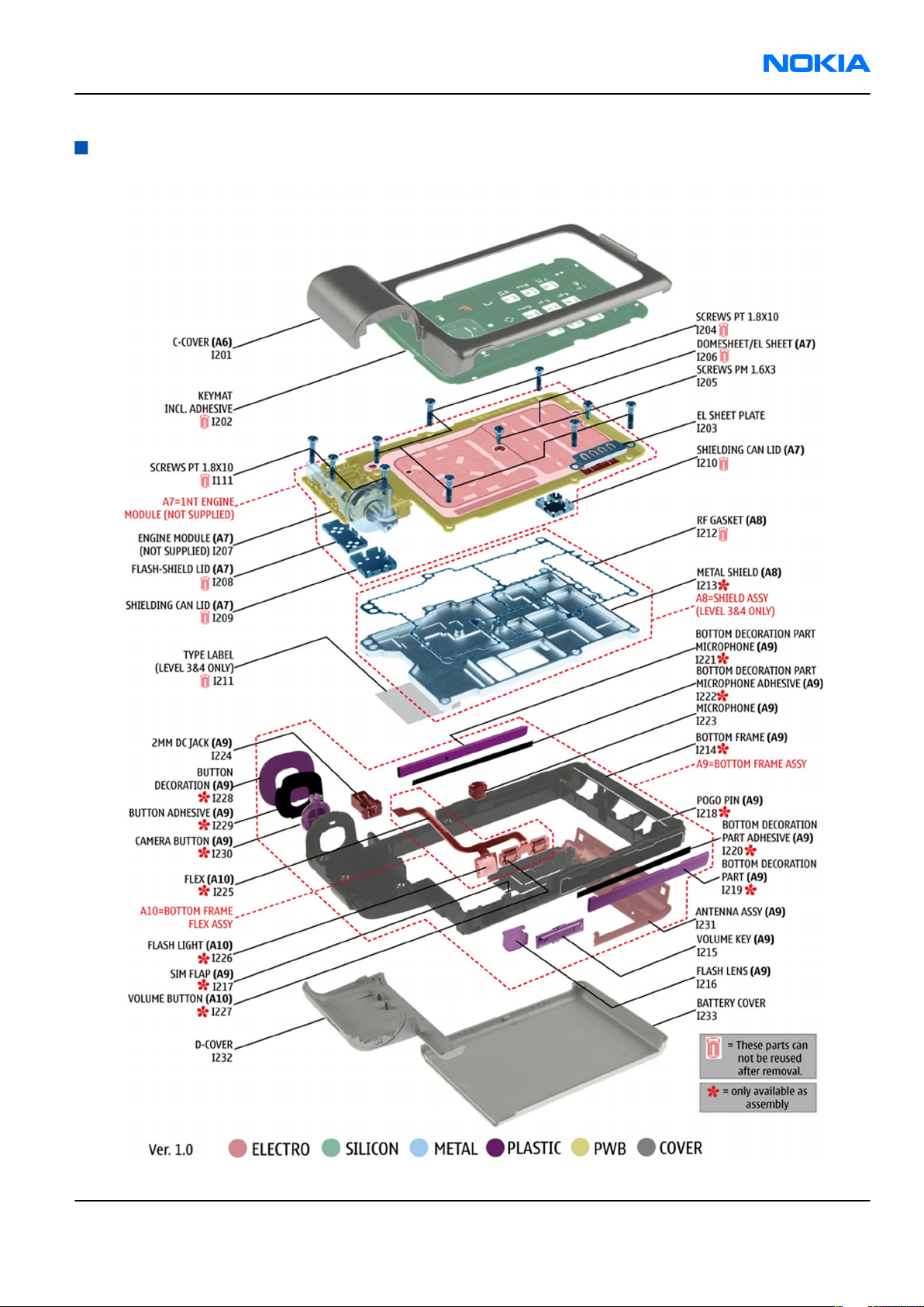
Exploded view
Figure 2 Bottom module exploded view
Issue 2 COMPANY CONFIDENTIAL Page 2 –5
Copyright © 2007 Nokia. All rights reserved.
Page 26
RM-100
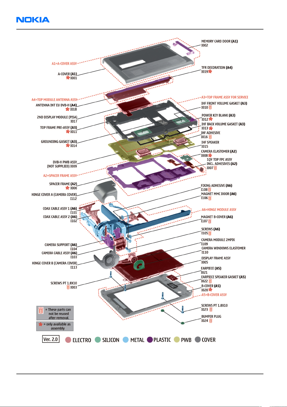
Nokia Customer Care Parts Lists and Component Layouts
Figure 3 Top module and hinge exploded view
Page 2 –6 COMPANY CONFIDENTIAL Issue 2
Copyright © 2007 Nokia. All rights reserved.
Page 27

RM-100
Parts Lists and Component Layouts Nokia Customer Care
Mechanical spare parts list
Note: For Nokia product codes, please refer to the latest Service Bulletins on the Partner Website (PWS).
To ensure you are always using the latest codes, please check the PWS on a daily basis.
Ax and in bold = ASSY
"-" = NOT AVAILABLE
"XXXXXXX" = VARIANTS
"???????" = Code available in Bulletin
I0xx = ITEM codes for upper or mono block
I1xx = ITEM codes for hinge block
I2xx = ITEM codes for lower block
I3xx = ITEM codes for soldered spare parts on the upper, hinge or lower block and not exchangable
ITEM/CIRCUIT REF. QTY PART NO PART NAME NOTE
A1 1 XXXXXXX
A-COVER ASSY (I001
- I002)
I001 1 - A-COVER
MEMORY CARD
I002 1 XXXXXXX
DOOR
I003 2 ??????? SCREWS PT1.8x10
DISPLAY FRAME
I005 1 ???????
A2 1 ???????
ASSY
SPACER FRAME ASSY
(I006 - I008)
I006 1 - SPACER FRAME
1QY TOP FPC ASSY
I007 1 ???????
incl. ADHESIVES
CAMERA
I008 1 -
ELASTOMER
I009 1 ??????? DVB-H PWB ASSY
Cannot be reused
after removal
Cannot be reused
after removal
TOP FRAME ASSY
A3 1 XXXXXXX
FOR SERVICE(I010I014)
I010 2 ???????
IHF FRONT VOLUME
GASKET
Cannot be reused
after removal
TOP FRAME PRE-
I011 1 -
ASSY
I012 1 - POWER KEY BLANK
IHF BACK VOLUME
I013 1 -
GASKET
Issue 2 COMPANY CONFIDENTIAL Page 2 –7
Copyright © 2007 Nokia. All rights reserved.
Page 28
RM-100
Nokia Customer Care Parts Lists and Component Layouts
ITEM/CIRCUIT REF. QTY PART NO PART NAME NOTE
GROUNDING
I014 1 -
I015 2 ??????? IHF SPEAKER
I016 2 ??????? IHF ADHESIVE
I017 1 ???????
A4 1 XXXXXXX
I018 1 I019 1 - TFR DECORATION
GASKET
Cannot be reused
after removal
2nd DISPLAY
MODULE (PISA)
TOP MODULE
ANTENNA ASSY
(I017 - I018)
ANTENNA INT EU
DVB-H
A5 1 XXXXXXX
I020 1 - B-COVER
I021 1 ??????? EARPIECE
I022 1 ???????
I023 2 ??????? SCREWS PT1.8x10
I024 2 ??????? BUMPER PLUG
A6 1 XXXXXXX
I101 1 ??????? COAX CABLE ASSY 1
I102 1 ??????? COAX CABLE ASSY 2
I103 1 ???????
I104 1 ??????? CAMERA SUPPORT
B-COVER ASSY (I020
- I022)
EARPIECE SPEAKER
GASKET
HINGE MODULE
ASSY (I101 - I107)
CAMERA CABLE
ASSY
Cannot be reused
after removal
Cannot be reused
after removal
Cannot be reused
after removal
Cannot be reused
I105 2 ??????? SCREWS
I106 1 ??????? MAGNET MMC DOOR
I107 1 ??????? MAGNET B-COVER
I108 2 ??????? FIXING ADHESIVE
Page 2 –8 COMPANY CONFIDENTIAL Issue 2
Copyright © 2007 Nokia. All rights reserved.
after removal
Cannot be reused
after removal
Cannot be reused
after removal
Cannot be reused
after removal
Page 29
RM-100
Parts Lists and Component Layouts Nokia Customer Care
ITEM/CIRCUIT REF. QTY PART NO PART NAME NOTE
CAMERA MODULE
I109 1 ???????
I110 1 ???????
I111 3 ??????? SCREWS PT1.8x10
I112 1 XXXXXXX
I113 1 XXXXXXX
I201 1 XXXXXXX C-COVER
2Mpix
CAMERA WINDOW
ELASTOMER
Cannot be reused
after removal
HINGE COVER A
(CAMERA COVER)
HINGE COVER B
(CAMERA COVER)
KEYMAT incl.
I202 1 XXXXXXX
I203 1 ??????? EL-SHEET PLATE
I204 6 ??????? SCREWS PT1.8x10
I205 2 ??????? SCREWS PM1.6x3
A7 1 -
I206 1 ???????
I207 1 - ENGINE MODULE
I208 1 ??????? FLASH-SHIELD LID
I209 1 ??????? SHIELDING CAN LID
I210 1 ??????? SHIELDING CAN LID
ADHESIVE
1NT ENGINE
MODULE ASSY(I206
- I210)
DOMESHEET / EL
SHEET
Cannot be reused
after removal
Cannot be reused
after removal
Cannot be reused
after removal
Cannot be reused
after removal
Cannot be reused
after removal
Cannot be reused
after removal
Cannot be reused
I211 1 ??????? TYPE LABEL
A8 1 ???????
I212 1 ??????? RF GASKET
I213 1 - METAL SHIELD
A9 1 XXXXXXX
I214 1 - BOTTOM FRAME
Issue 2 COMPANY CONFIDENTIAL Page 2 –9
Copyright © 2007 Nokia. All rights reserved.
SHIELD ASSY(I212 I213)
BOTTOM FRAME
ASSY(I214 - I231)
after removal
Cannot be reused
after removal
Page 30
RM-100
Nokia Customer Care Parts Lists and Component Layouts
ITEM/CIRCUIT REF. QTY PART NO PART NAME NOTE
I215 1 XXXXXXX VOLUME KEY
I216 1 ??????? FLASH LENS
I217 1 - SIM FLAP
I218 4 - POGO PIN
BOTTOM
I219 1 -
I220 1 -
I221 1 -
I222 1 -
DECORATION PART
BOTTOM
DECORATION PART
ADHESIVE
BOTTOM
DECORATION PART
MICROPHONE
BOTTOM
DECORATION PART
MICROPHONE
ADHESIVE
I223 1 ??????? MICROPHONE
I224 1 ??????? 2 mm DC JACK
BOTTOM FRAME
A10 1 ???????
I225 1 - FLEX
I226 1 - FLASH LIGHT
I227 2 - VOLUME BUTTON
I228 1 I229 1 - BUTTON ADHESIVE
I230 1 - CAMERA BUTTON
I231 1 XXXXXXX ANTENNA ASSY
I232 1 XXXXXXX D-COVER
I233 1 XXXXXXX BATTERY COVER
FLEX ASSY(I225 -
I227)
BUTTON
DECORATION
Component parts lists and layouts 1NT_15a
Component parts list 1NT_14a
ITEM SIDE GRID REF. TYPE DESCRIPTION AND VALUE
SHIELDING CAN
SHIELD_040_
A1001 Top F 3
Page 2 –10 COMPANY CONFIDENTIAL Issue 2
Copyright © 2007 Nokia. All rights reserved.
018734
ASSEMBLY
1.9X7.9X8.85 ~ ~
Page 31

RM-100
Parts Lists and Component Layouts Nokia Customer Care
ITEM SIDE GRID REF. TYPE DESCRIPTION AND VALUE
SHIELD_040_
A4400 Top S 9
A5200 Top S 7
B2200 Top J 10
C2000 Top R 10 0402C Chipcap 5% NP0 27p 50V
C2002 Top M 10 0402C Chipcap 5% NP0 10p 50V
C2003 Top M 10 0402C Chipcap 5% NP0 10p 50V
C2005 Top N 9 0402C
C2006 Top N 9 0402C
C2009 Top M 10 0402C Chipcap 5% NP0 10p 50V
C2010 Top M 10 0402C Chipcap 5% NP0 10p 50V
C2012 Bottom R 10 0603C
013073
SHIELD_040_
018734
CRYSTAL_3.3X
1.6_H0.9
FLASH-SHIELD
ASSEMBLY ~ ~
SHIELDING CAN
ASSEMBLY
1.9X7.9X8.85 ~ ~
CRYSTAL
32.768KHZ
+-30PPM 12.5PF 32.768kHz ~
chipcap x7r 47n k
10v 0402 47n 10V
chipcap x7r 47n k
10v 0402 47n 10V
CHIPCAP X5R 220N
K 25V 0603 220n 25V
CHIPCAP X5R 220N
C2013 Bottom R 10 0603C
TANT_C_6.2X
C2070 Top R 9
C2071 Top Q 7 0402C Chipcap 5% NP0 15p 50V
C2100 Top J 10 0402C
C2120 Top K 9 0402C_H0.6
C2121 Top K 9 0402C_H0.6
C2123 Top L 8 0402C
C2124 Top K 9 0402C_H0.6
C2125 Top K 9 0402C_H0.6
C2127 Top J 10 0402C
3.4_H1.7
K 25V 0603 220n 25V
CHIPTCAP 150U M
10V 6X3.2X1.5 150u_10V 10V
Chipcap X7R 10%
16V 0402 10n 16V
CHIPCAP X5R 100N
K 16V 0402 100n 16V
CHIPCAP X5R 100N
K 16V 0402 100n 16V
CHIPCAP X5R 1U K
6V3 0402 1u0 6.3V
CHIPCAP X5R 100N
K 16V 0402 100n 16V
CHIPCAP X5R 100N
K 16V 0402 100n 16V
Chipcap X7R 10%
50V 0402 1n0 50V
Chipcap X7R 10%
C2128 Top J 10 0402C
Issue 2 COMPANY CONFIDENTIAL Page 2 –11
Copyright © 2007 Nokia. All rights reserved.
50V 0402 1n0 50V
Page 32

RM-100
Nokia Customer Care Parts Lists and Component Layouts
ITEM SIDE GRID REF. TYPE DESCRIPTION AND VALUE
Chipcap X7R 10%
C2129 Top J 10 0402C
C2130 Top K 10 0402C
C2131 Top K 10 0402C
C2132 Top K 10 0402C
C2133 Top L 10 0402C_H0.6
C2134 Top L 9 0805C
C2135 Top L 9 0402C
50V 0402 1n0 50V
Chipcap X7R 10%
50V 0402 1n0 50V
Chipcap X7R 10%
50V 0402 1n0 50V
Chipcap X7R 10%
50V 0402 1n0 50V
CHIPCAP X5R 100N
K 16V 0402 100n 16V
CHIPCAP X5R 10U
M 6V3 0805 10U 6V3
CHIPCAP X5R 1U K
6V3 0402 1u0 6.3V
C2200 Top K 9 0603C
C2201 Top I 9 0402C
C2202 Top K 9 0603C
C2205 Top K 9 0402C
C2211 Top I 8 0805C
C2213 Top I 9 0405_DUAL
C2215 Top I 9 0405_DUAL
C2216 Top I 10 0402C
C2217 Top K 9 0402C
CHIPCAP X5R 2U2 K
6V3 0603 2u2 6V3
CHIPCAP X5R 1U5 K
4V 0402 1u5 4V
CHIPCAP X5R 2U2 K
6V3 0603 2u2 6V3
Chipcap X7R 10%
50V 0402 1n0 50V
CHIPCAP X5R 4U7 K
10V 0805 4u7 10V
CHIPCAP NETWORK
X5R 2X1U5 K 6V3
0405 2x1u5 6.3V
CHIPCAP NETWORK
X5R 2X1U5 K 6V3
0405 2x1u5 6.3V
CHIPCAP X5R 1U5 K
4V 0402 1u5 4V
CHIPCAP X5R 1U5 K
4V 0402 1u5 4V
CHIPCAP NETWORK
X5R 2X1U5 K 6V3
C2220 Top J 8 0405_DUAL
C2222 Top I 8 0603C
C2225 Top J 8 0603C
Page 2 –12 COMPANY CONFIDENTIAL Issue 2
Copyright © 2007 Nokia. All rights reserved.
0405 2x1u5 6.3V
CHIPCAP X5R 1U K
6V3 0603 1u0 6.3V
CHIPCAP X5R 1U K
6V3 0603 1u0 6.3V
Page 33

RM-100
Parts Lists and Component Layouts Nokia Customer Care
ITEM SIDE GRID REF. TYPE DESCRIPTION AND VALUE
CHIPCAP X5R 1U K
C2226 Top I 9 0603C
C2227 Top I 9 0405_DUAL
C2228 Top I 8 0405_DUAL
C2231 Top K 8 0805C
C2232 Top I 8 0405_DUAL
C2300 Top N 9 0402C
6V3 0603 1u0 6.3V
CHIPCAP NETWORK
X5R 2X1U5 K 6V3
0405 2x1u5 6.3V
CHIPCAP NETWORK
X5R 2X1U5 K 6V3
0405 2x1u5 6.3V
CHIPCAP X5R 10U
M 6V3 0805 10U 6V3
CHIPCAP NETWORK
X5R 2X1U5 K 6V3
0405 2x1u5 6.3V
Chipcap X7R 10%
16V 0402 10n 16V
C2301 Top N 9 0805C
C2302 Top L 9 0805C
C2303 Top N 7 0603C
C2304 Top N 8 0402C
C2307 Top N 7 0603C
C2308 Top P 8 0402C
C2309 Top O 9 0805C
C2312 Top O 8 0405_DUAL
C2314 Top O 8 0805C
CHIPCAP X5R 22U
M 6V3 0805 22u 6V3
CHIPCAP X5R 22U
M 6V3 0805 22u 6V3
CHIPCAP X5R 1U K
6V3 0603 1u0 6.3V
Chipcap X7R 10%
16V 0402 10n 16V
CHIPCAP X5R 1U K
6V3 0603 1u0 6.3V
CHIPCAP X5R 1U K
6V3 0402 1u0 6.3V
CHIPCAP X5R 22U
M 6V3 0805 22u 6V3
CHIPCAP NETWORK
X5R 2X1U5 K 6V3
0405 2x1u5 6.3V
CHIPCAP X5R 4U7
M 25V 0805 4u7 25V
CHIPCAP X5R 100N
C2700 Top H 2 0402C_H0.6
C2800 Top L 6 0402C_H0.6
C2801 Top J 6 0402C_H0.6
C2802 Top L 6 0402C_H0.6
Issue 2 COMPANY CONFIDENTIAL Page 2 –13
Copyright © 2007 Nokia. All rights reserved.
K 16V 0402 100n 16V
CHIPCAP X5R 100N
K 16V 0402 100n 16V
CHIPCAP X5R 100N
K 16V 0402 100n 16V
CHIPCAP X5R 100N
K 16V 0402 100n 16V
Page 34

RM-100
Nokia Customer Care Parts Lists and Component Layouts
ITEM SIDE GRID REF. TYPE DESCRIPTION AND VALUE
CHIPCAP X5R 100N
C2803 Top L 4 0402C_H0.6
C2804 Top J 4 0402C_H0.6
C2805 Top K 7 0402C_H0.6
C2806 Top K 7 0402C_H0.6
C2807 Top J 7 0402C_H0.6
C2808 Top J 6 0402C_H0.6
C2809 Top L 6 0402C_H0.6
K 16V 0402 100n 16V
CHIPCAP X5R 100N
K 16V 0402 100n 16V
CHIPCAP X5R 100N
K 16V 0402 100n 16V
CHIPCAP X5R 100N
K 16V 0402 100n 16V
CHIPCAP X5R 100N
K 16V 0402 100n 16V
CHIPCAP X5R 100N
K 16V 0402 100n 16V
CHIPCAP X5R 100N
K 16V 0402 100n 16V
C2810 Top K 7 0402C_H0.6
C2811 Top J 4 0402C_H0.6
C2812 Top L 7 0402C_H0.6
C2813 Top L 7 0402C_H0.6
C2814 Top L 5 0402C_H0.6
C2815 Top K 4 0402C_H0.6
C2816 Top L 5 0402C_H0.6
C2817 Top J 4 0402C_H0.6
C2818 Top L 7 0402C_H0.6
C2819 Top K 4 0402C_H0.6
CHIPCAP X5R 100N
K 16V 0402 100n 16V
CHIPCAP X5R 100N
K 16V 0402 100n 16V
CHIPCAP X5R 100N
K 16V 0402 100n 16V
CHIPCAP X5R 100N
K 16V 0402 100n 16V
CHIPCAP X5R 100N
K 16V 0402 100n 16V
CHIPCAP X5R 100N
K 16V 0402 100n 16V
CHIPCAP X5R 100N
K 16V 0402 100n 16V
CHIPCAP X5R 100N
K 16V 0402 100n 16V
CHIPCAP X5R 100N
K 16V 0402 100n 16V
CHIPCAP X5R 100N
K 16V 0402 100n 16V
CHIPCAP X5R 100N
C2820 Top J 7 0402C_H0.6
C2821 Top L 7 0402C_H0.6
C2822 Top K 4 0402C_H0.6
C3100 Top I 7 0402C Chipcap 5% NP0 27p 50V
Page 2 –14 COMPANY CONFIDENTIAL Issue 2
Copyright © 2007 Nokia. All rights reserved.
K 16V 0402 100n 16V
CHIPCAP X5R 100N
K 16V 0402 100n 16V
CHIPCAP X5R 100N
K 16V 0402 100n 16V
Page 35

RM-100
Parts Lists and Component Layouts Nokia Customer Care
ITEM SIDE GRID REF. TYPE DESCRIPTION AND VALUE
CHIPCAP X5R 22U
C4200 Top L 7 0805C
C4201 Top M 7 0805C
C4202 Top N 7 0402C
C4224 Bottom T 5 0603C_H0.95
C4226 Bottom T 6 0603C_H0.95
C4401 Bottom S 7 0402C_H0.6
C4402 Bottom S 7 0402C Chipcap 5% NP0 56p 50V
C4403 Top O 9 0402C Chipcap 5% NP0 10p 50V
M 6V3 0805 22u 6V3
CHIPCAP X5R 22U
M 6V3 0805 22u 6V3
Chipcap X7R 10%
16V 0402 10n 16V
CHIPCAP X5R 1U K
25V 0603 1u0 25V
CHIPCAP X5R 1U K
25V 0603 1u0 25V
CHIPCAP X5R 100N
K 16V 0402 100n 16V
C4404 Bottom S 7 0402C Chipcap 5% NP0 56p 50V
CHIPCAP X5R 100N
C4405 Top O 7 0402C_H0.6
C4406 Bottom S 6 0402C Chipcap 5% NP0 56p 50V
C4407 Bottom R 6 0402C Chipcap 5% NP0 56p 50V
C4408 Bottom R 8 0402C Chipcap 5% NP0 56p 50V
C4409 Bottom S 8 0402C_H0.6
C4410 Bottom S 8 0402C Chipcap 5% NP0 56p 50V
C4411 Top S 10 0402C Chipcap 5% NP0 56p 50V
C4412 Top S 10 0402C_H0.6
C4413 Top R 10 0402C Chipcap 5% NP0 56p 50V
C4414 Top T 10 0402C Chipcap 5% NP0 56p 50V
C4415 Top T 10 0402C_H0.6
C4416 Top T 10 0402C Chipcap 5% NP0 56p 50V
K 16V 0402 100n 16V
CHIPCAP X5R 100N
K 16V 0402 100n 16V
CHIPCAP X5R 100N
K 16V 0402 100n 16V
CHIPCAP X5R 100N
K 16V 0402 100n 16V
C4417 Top S 10 0402C Chipcap 5% NP0 56p 50V
CHIPCAP X5R 100N
C4418 Top S 10 0402C_H0.6
C4419 Top S 10 0402C Chipcap 5% NP0 56p 50V
C4420 Top T 6 0402C_H0.6
Issue 2 COMPANY CONFIDENTIAL Page 2 –15
Copyright © 2007 Nokia. All rights reserved.
K 16V 0402 100n 16V
CHIPCAP X5R 100N
K 16V 0402 100n 16V
Page 36

RM-100
Nokia Customer Care Parts Lists and Component Layouts
ITEM SIDE GRID REF. TYPE DESCRIPTION AND VALUE
CHIPCAP X5R 4U7 K
C4421 Top T 5 0603C
C4422 Top T 6 0402C_H0.6
C4423 Top S 10 0402C Chipcap 5% NP0 56p 50V
C4424 Top R 10 0402C_H0.6
C4425 Top S 10 0402C Chipcap 5% NP0 56p 50V
C4426 Bottom R 8 0402C_H0.6
C4427 Bottom R 8 0402C Chipcap 5% NP0 56p 50V
C4428 Bottom R 8 0402C Chipcap 5% NP0 56p 50V
C4429 Bottom R 8 0402C_H0.6
6V3 0603 4u7 6.3V
CHIPCAP X5R 100N
K 16V 0402 100n 16V
CHIPCAP X5R 100N
K 16V 0402 100n 16V
CHIPCAP X5R 100N
K 16V 0402 100n 16V
CHIPCAP X5R 100N
K 16V 0402 100n 16V
C4430 Top G 4 0402C Chipcap 5% NP0 56p 50V
Chipcap X7R 10%
C4431 Top H 4 0402C
C4433 Top G 5 0402C
C4435 Top H 4 0603C Cer cap 5% X7R 10n 50V
C4437 Top H 5 0603C
C4438 Top P 5 0402C_H0.6
C4439 Top R 7 0402C
C4440 Bottom S 8 0402C Chipcap 5% NP0 56p 50V
C4441 Bottom S 8 0402C Chipcap 5% NP0 56p 50V
C4442 Top R 9 0603C
C4443 Top S 9 0603C
25V 0402 6n8 25V
CHIPCAP X5R 1U K
6V3 0402 1u0 6.3V
CHIPCAP X5R 1U K
6V3 0603 1u0 6.3V
CHIPCAP X5R 100N
K 16V 0402 100n 16V
Chipcap X7R 10%
16V 0402 10n 16V
CHIPCAP X5R 10UF
6V3 0603 10u 4V
CHIPCAP X5R 4U7 K
6V3 0603 4u7 6.3V
CHIPCAP X5R 1U K
C4444 Bottom T 9 0603C
C4445 Bottom T 9 0603C
C4446 Bottom T 8 0402C
C4450 Bottom T 7 0402C Chipcap 5% NP0 10p 50V
Page 2 –16 COMPANY CONFIDENTIAL Issue 2
Copyright © 2007 Nokia. All rights reserved.
6V3 0603 1u0 6.3V
CHIPCAP X5R 1U K
6V3 0603 1u0 6.3V
Chipcap X7R 10%
16V 0402 10n 16V
Page 37

RM-100
Parts Lists and Component Layouts Nokia Customer Care
ITEM SIDE GRID REF. TYPE DESCRIPTION AND VALUE
C4451 Bottom T 7 0402C Chipcap 5% NP0 10p 50V
C4452 Top I 4 0603C Cer cap 5% X7R 10n 50V
C4453 Bottom R 10 0402C Chipcap 5% NP0 27p 50V
C4454 Bottom R 10 0402C Chipcap 5% NP0 27p 50V
C4459 Bottom R 8 0402C Chipcap 5% NP0 56p 50V
C4460 Bottom S 8 0402C Chipcap 5% NP0 56p 50V
C4600 Top T 7 0402C Chipcap 5% NP0 22p 50V
CHIPCAP X5R 100N
C4601 Top T 7 0402C_H0.6
C4602 Top T 7 0402C_H0.6
C4603 Top T 9 0603C
K 16V 0402 100n 16V
CHIPCAP X5R 100N
K 16V 0402 100n 16V
CHIPCAP X5R 4U7 K
6V3 0603 4u7 6.3V
C4800 Top M 4 0402C_H0.6
C4801 Top O 5 0603C
C4802 Top O 7 0402C_H0.6
C4803 Top M 4 0402C_H0.6
C4804 Top L 6 0402C_H0.6
C4805 Top O 5 0402C_H0.6
C4806 Top N 7 0402C_H0.6
C4807 Top L 5 0402C_H0.6
C4808 Top L 5 0402C_H0.6
C4809 Top M 4 0402C_H0.6
CHIPCAP X5R 100N
K 16V 0402 100n 16V
CHIPCAP X5R 1U K
6V3 0603 1u0 6.3V
CHIPCAP X5R 100N
K 16V 0402 100n 16V
CHIPCAP X5R 100N
K 16V 0402 100n 16V
CHIPCAP X5R 100N
K 16V 0402 100n 16V
CHIPCAP X5R 100N
K 16V 0402 100n 16V
CHIPCAP X5R 100N
K 16V 0402 100n 16V
CHIPCAP X5R 100N
K 16V 0402 100n 16V
CHIPCAP X5R 100N
K 16V 0402 100n 16V
CHIPCAP X5R 100N
K 16V 0402 100n 16V
CHIPCAP X5R 100N
C4810 Top O 4 0402C_H0.6
C4811 Top L 6 0402C_H0.6
C4812 Top N 7 0402C_H0.6
Issue 2 COMPANY CONFIDENTIAL Page 2 –17
Copyright © 2007 Nokia. All rights reserved.
K 16V 0402 100n 16V
CHIPCAP X5R 100N
K 16V 0402 100n 16V
CHIPCAP X5R 100N
K 16V 0402 100n 16V
Page 38

RM-100
Nokia Customer Care Parts Lists and Component Layouts
ITEM SIDE GRID REF. TYPE DESCRIPTION AND VALUE
CHIPCAP X5R 100N
C5000 Top M 2 0402C_H0.6
C5001 Top M 2 0402C_H0.6
C5002 Top M 2 0402C_H0.6
C5003 Top M 2 0402C_H0.6
C5004 Top M 4 0402C_H0.6
C5005 Top M 3 0402C_H0.6
C5006 Top M 2 0603C
K 16V 0402 100n 16V
CHIPCAP X5R 100N
K 16V 0402 100n 16V
CHIPCAP X5R 100N
K 16V 0402 100n 16V
CHIPCAP X5R 100N
K 16V 0402 100n 16V
CHIPCAP X5R 100N
K 16V 0402 100n 16V
CHIPCAP X5R 100N
K 16V 0402 100n 16V
CHIPCAP X5R 1U K
6V3 0603 1u0 6.3V
CHIPCAP X5R 4U7 K
C5200 Bottom T 7 0603C
C5201 Top R 7 0402C_H0.6
C5202 Top R 7 0402C_H0.6
C6040 Top B 9 0402C_H0.6
C6041 Top D 9 0402C
C6042 Top D 9 0402C
C6043 Top K 7 0402C_H0.6
C6044 Top J 7 0402C_H0.6
C6047 Top E 10 0402C Chipcap 5% NP0 100p 50V
C6048 Top F 9 0402C
6V3 0603 4u7 6.3V
CHIPCAP X5R 100N
K 16V 0402 100n 16V
CHIPCAP X5R 100N
K 16V 0402 100n 16V
CHIPCAP X5R 100N
K 16V 0402 100n 16V
CHIPCAP X5R 1U K
6V3 0402 1u0 6.3V
CHIPCAP X5R 1U K
6V3 0402 1u0 6.3V
CHIPCAP X5R 100N
K 16V 0402 100n 16V
CHIPCAP X5R 100N
K 16V 0402 100n 16V
Chipcap +-0.25pF
NP0 2p2 50V
Chipcap +-0.25pF
C6049 Top F 9 0402C
C6300 Top F 10 0603C
C6301 Top F 9 0603C
C6302 Top E 8 0402C
Page 2 –18 COMPANY CONFIDENTIAL Issue 2
Copyright © 2007 Nokia. All rights reserved.
NP0 1p8 50V
CHIPCAP X5R 4U7 K
6V3 0603 4u7 6.3V
CHIPCAP X5R 4U7 K
6V3 0603 4u7 6.3V
CHIPCAP X7R 33N K
10V 0402 33n 10V
Page 39

RM-100
Parts Lists and Component Layouts Nokia Customer Care
ITEM SIDE GRID REF. TYPE DESCRIPTION AND VALUE
Chipcap X7R 10%
C6303 Top E 8 0402C
C6304 Top H 7 0603C
C6305 Top H 9 0402C
C6306 Top E 9 0603C
C6310 Top H 9 0402C_H0.6
C7500 Top G 5 0603C
C7501 Top E 3 0603C
16V 0402 10n 16V
CHIPCAP X5R 4U7 K
6V3 0603 4u7 6.3V
CHIPCAP X7R 33N K
10V 0402 33n 10V
CHIPCAP X5R 4U7 K
6V3 0603 4u7 6.3V
CHIPCAP X5R 100N
K 16V 0402 100n 16V
CHIPCAP X5R 4U7 K
6V3 0603 4u7 6.3V
CHIPCAP X5R 4U7 K
6V3 0603 4u7 6.3V
CHIPCAP X5R 4U7 K
C7502 Top E 3 0603C
C7503 Top G 5 0603C
C7504 Top E 2 0402C Chipcap 5% X7R 3n9 50V
C7505 Top E 3 0402C
C7507 Top F 6 0402C_H0.6
C7508 Top F 2 0402C Chipcap 5% NP0 10p 50V
C7509 Top F 2 0402C_H0.6
C7510 Top F 3 0402C
C7511 Top E 2 0402C
C7512 Top F 3 0603C
6V3 0603 4u7 6.3V
CHIPCAP X5R 4U7 K
6V3 0603 4u7 6.3V
Chipcap X7R 10%
16V 0402 10n 16V
CHIPCAP X5R 100N
K 16V 0402 100n 16V
CHIPCAP X5R 100N
K 16V 0402 100n 16V
CHPCAP NP0 470P J
50V 0402 470p 50V
CHIPCAP X7R 33N K
10V 0402 33n 10V
CHIPCAP NP0 2N2
G 16V 0603 2n2 16V
Chipcap +-0.25pF
C7514 Top F 6 0402C
C7515 Top E 6 0402C
C7521 Top D 7 0603C
C7522 Top C 5 0603C
Issue 2 COMPANY CONFIDENTIAL Page 2 –19
Copyright © 2007 Nokia. All rights reserved.
NP0 2p2 50V
Chipcap +-0.25pF
NP0 4p7 50V
CHIPCAP X5R 4U7 K
6V3 0603 4u7 6.3V
CHIPCAP X5R 1U K
6V3 0603 1u0 6.3V
Page 40

RM-100
Nokia Customer Care Parts Lists and Component Layouts
ITEM SIDE GRID REF. TYPE DESCRIPTION AND VALUE
CHIPCAP X5R 4U7 K
C7541 Top C 4 0603C
C7542 Top C 4 0603C
C7543 Top B 4 0603C
C7544 Top D 3 0402C
C7545 Top C 2 0402C Chipcap 5% NP0 10p 50V
C7547 Top D 3 0402C
C7550 Top C 7 0402C Chipcap 5% NP0 10p 50V
C7551 Top C 7 0402C
6V3 0603 4u7 6.3V
CHIPCAP X5R 4U7 K
6V3 0603 4u7 6.3V
CHIPCAP X5R 4U7 K
6V3 0603 4u7 6.3V
CERCAP X7R 22N K
16V 0402 22n 16V
Chipcap +-0.25pF
NP0 2p7 50V
Chipcap NP0 2P7 B
50V 0402 2p7 50V
Chipcap +-0.25pF
C7552 Top C 8 0402C
C7555 Top F 6 0402C
C7560 Top F 7 0402C Chipcap 5% NP0 100p 50V
C7561 Top D 7 0402C
C7583 Top C 2 0402C
D2800 Top K 6 VFBGA343
FBGA128_EM
D3000 Top K 6
D4400 Top O 7 SC70_5
D4800 Top N 5 uBGA_289
PTY
NP0 3p9 50V
Chipcap +-0.25pF
NP0 5p6 50V
Chipcap X7R 10%
16V 0402 10n 16V
CHIPCAP NP0 HQ
1.0P B 16V 0402 1p0 16V
RAP3GS V2.0E-PA
VFBGA ~ ~
COMBO 128M NOR
+128M DDR DRAM
FBGA128 8Mx16/8Mx16 ~
BUFFER
74LVC1G126
SOT353 ~ ~
HELEN3 PS2.0 N3
SS F761909 C027
UBGA289 ~ ~
COMBO 512 DDR +
FBGA133_11.
D5000 Top N 3
D5200 Top S 7 TFBGA84
D6035 Top C 9
Page 2 –20 COMPANY CONFIDENTIAL Issue 2
Copyright © 2007 Nokia. All rights reserved.
6X13.1
LGA_BTHFM_E
S3.6
1G NAND FBGA133
PBFREE 32Mx16/128Mx8 ~
HW ACCELERATOR
STV0984N ~ ~
BTHFM1.0 BALUN
ONLY SOLUTION ~ ~
Page 41

RM-100
Parts Lists and Component Layouts Nokia Customer Care
ITEM SIDE GRID REF. TYPE DESCRIPTION AND VALUE
0402_FUSE_A
F2000 Top R 10
G2200 Top G 9
G7500 Top E 3
G7501 Top F 3
L2000 Top R 10 0603_BLM
L2001 Top N 10
L2002 Top M 9
L2003 Top M 9
VX_H0.5
BATTER_EECE
P
NKG3176B_H
1.0
VCO_DCS0273
3
0405_2_MATSUCHIP BEAD ARRAY
0405_2_MATSUCHIP BEAD ARRAY
0405_2_MATSUCHIP BEAD ARRAY
SM FUSE FF 2A 32V
0402 2.0A ~
RTC BACUP CAPAC
311 SIZE FOR 2.6V
4UAH 2.6V ~
VCTCXO 38.4MHZ
2.5V 2MA 38.4MHz ~
VCO
3296-3980MHZ 4BAND MATSUSHITA 3296-3980MHz ~
FERR.BEAD 220R/
100M 2A 0R05
0603 220R/100MHz ~
2X1000R 0405 2x1000R/100MHz ~
2X1000R 0405 2x1000R/100MHz ~
2X1000R 0405 2x1000R/100MHz ~
FERRITE_040
L2004 Top O 10
L2005 Top O 10
L2006 Top O 10
L2010 Top M 10 0402L_XL
L2120 Top L 9 0603_BLM
L2121 Top J 10 0603_BLM
L2122 Top K 10 0603_BLM
2
FERRITE_040
2
FERRITE_040
2
FERRITE BEAD 0.6R
600R/100MHZ
0402 600R/100MHz ~
FERRITE BEAD 0.6R
600R/100MHZ
0402 600R/100MHz ~
FERRITE BEAD 0.6R
600R/100MHZ
0402 600R/100MHz ~
CHIP COIL 68N J
Q17/300M 0402 68nH ~
FERR.BEAD 220R/
100M 2A 0R05
0603 220R/100MHz ~
FERR.BEAD 220R/
100M 2A 0R05
0603 220R/100MHz ~
FERR.BEAD 220R/
100M 2A 0R05
0603 220R/100MHz ~
FERR.BEAD 220R/
100M 2A 0R05
L2123 Top K 10 0603_BLM
Issue 2 COMPANY CONFIDENTIAL Page 2 –21
Copyright © 2007 Nokia. All rights reserved.
0603 220R/100MHz ~
Page 42

RM-100
Nokia Customer Care Parts Lists and Component Layouts
ITEM SIDE GRID REF. TYPE DESCRIPTION AND VALUE
FERR.BEAD 220R/
100M 2A 0R05
L2124 Top K 10 0603_BLM
L2202 Top J 8 0603_BLM
FERRITE_040
L2203 Top I 8
L2204 Top I 9
L2205 Top K 8 0603_BLM
2
FERRITE_040
2
0603 220R/100MHz ~
FERR.BEAD 220R/
100M 2A 0R05
0603 220R/100MHz ~
FERRITE BEAD 0.6R
600R/100MHZ
0402 600R/100MHz ~
FERRITE BEAD 0.6R
600R/100MHZ
0402 600R/100MHz ~
FERR.BEAD 220R/
100M 2A 0R05
0603 220R/100MHz ~
FERRITE_040
L2206 Top I 8
L2301 Top N 9 0603_BLM
L2302 Top M 9
L2304 Top O 9
L4200 Top M 8
L4201 Top N 7 0603_BLM
L4401 Bottom S 7
L4404 Top P 9
2
CHOKE_SER40
0_H1.2
CHOKE_SER30
0_H1.5
CHOKE_SER400CHOKE 10U 0.8A
FERRITE_040
2
FERRITE_040
2
FERRITE BEAD 0.6R
600R/100MHZ
0402 600R/100MHz ~
FERR.BEAD 220R/
100M 2A 0R05
0603 220R/100MHz ~
INDUCT WW 10UH
0A65 0R35
4X4X1.2 10uH ~
CHOKE 22U M 0R7
0.35A 3.0x3.0x1.5 22uH ~
0R24 4X4X1.8 10uH ~
FERR.BEAD 220R/
100M 2A 0R05
0603 220R/100MHz ~
FERRITE BEAD 0.6R
600R/100MHZ
0402 600R/100MHz ~
FERRITE BEAD 0.6R
600R/100MHZ
0402 600R/100MHz ~
FERRITE BEAD 0.6R
FERRITE_040
L4406 Bottom R 6
L4408 Bottom S 8
Page 2 –22 COMPANY CONFIDENTIAL Issue 2
Copyright © 2007 Nokia. All rights reserved.
2
FERRITE_040
2
600R/100MHZ
0402 600R/100MHz ~
FERRITE BEAD 0.6R
600R/100MHZ
0402 600R/100MHz ~
Page 43

RM-100
Parts Lists and Component Layouts Nokia Customer Care
ITEM SIDE GRID REF. TYPE DESCRIPTION AND VALUE
FERR.BEAD 220R/
100M 2A 0R05
L4411 Top S 10 0603_BLM
FERRITE_040
L4414 Top T 10
L4417 Top S 10
2
FERRITE_040
2
0603 220R/100MHz ~
FERRITE BEAD 0.6R
600R/100MHZ
0402 600R/100MHz ~
FERRITE BEAD 0.6R
600R/100MHZ
0402 600R/100MHz ~
CHOKE_SER30
L4420 Top S 5
L4423 Top R 10
L4426 Bottom R 8
L4429 Bottom S 8
L4430 Top G 6
L4435 Top H 5
L4441 Top S 8
L6000 Top F 9 0402L
0_H1.5
FERRITE_040
2
FERRITE_040
2
FERRITE_040
2
CHOKE_ELT3K
N152C
FERRITE_040
2
CHOKE_SER300INDUCT WW 2.2UH
CHOKE 3U3 1.2A
0R096 3X3X1.5 3u3H ~
FERRITE BEAD 0.6R
600R/100MHZ
0402 600R/100MHz ~
FERRITE BEAD 0.6R
600R/100MHZ
0402 600R/100MHz ~
FERRITE BEAD 0.6R
600R/100MHZ
0402 600R/100MHz ~
COIL 0.47MH 50MA
3.3X3.4X1.4MM 0.47MH ~
FERRITE BEAD 0.6R
600R/100MHZ
0402 600R/100MHz ~
1A2 310 CASE SIZE 2u2H ~
CHIP COIL 2N7
+-0N3 Q29/800M
0402 2n7H ~
CHOKE_SER300INDUCT WW 2.2UH
L6300 Top E 9
FERRITE_040
L7500 Top G 4
L7501 Top E 6 0402L_POL2
L7502 Top F 6 0402L
L7520 Top D 4
Issue 2 COMPANY CONFIDENTIAL Page 2 –23
Copyright © 2007 Nokia. All rights reserved.
2
FERRITE_FBMJ
1608
1A2 310 CASE SIZE 2u2H ~
FERRITE BEAD 0.6R
600R/100MHZ
0402 600R/100MHz ~
CHIP COIL 12N J
Q30/250MHZ 0402 12nH ~
CHIP COIL 8N2 J
Q25/100MHZ 0402 8.2nH ~
FERRITE BEAD
0R01 28R/100MHZ
0603 28R/100MHz ~
Page 44

RM-100
Nokia Customer Care Parts Lists and Component Layouts
ITEM SIDE GRID REF. TYPE DESCRIPTION AND VALUE
CHOKE_SER30
L7540 Top C 4
L7543 Top D 3 0402L
L7550 Top D 8 0402L
L7551 Top C 8 0402L
L7555 Top F 6 0402L_H0.45
L7582 Top C 2
L7583 Top D 2
N2100 Top K 8 QFN3X3_16A
0_H1.5
FERRITE_LQP
10
0402L_W065
_POL
CHOKE 3U3 1.2A
0R096 3X3X1.5 3u3H ~
CHIP COIL 3N9
+-0N3 Q28/800M
0402 3n9H ~
CHIP COIL 10N J
Q30/800M 0402 10nH ~
CHIP COIL 18N J
Q29/800M 0402 18nH ~
CHIP COIL 5N6
+-0N1 Q26/1GHZ
0402 5n6H ~
CHIP COIL 1N5
+-0N1 Q45/1GHZ
0402 1n5H ~
CHIP COIL 3N9
+-0N1 Q28/1GHZ
0402 3n9H ~
QUAD ANALOG
SWITCH STG3699
QFN16 ~ ~
N2101 Top K 9 XBGA_N16
N2200 Top J 9 TFBGA_105
TFBGA64_H1.2BETTY V2.1 LF
N2300 Top N 8
USMD_10_2.4
N4200 Top M 8
N4420 Top T 5 SON3024_8
N4430 Top G 5 MSOP_10
N4441 Top S 9
N4442 Bottom T 9
58X1.899
USMD5_1.417
X1.087
USMD5_1.47X
1.04_H0.675
AF AMP
TPA2012D2 77DB/
217HZ WCSP16 ~ ~
AVILMA 1.05C BB
MODULE TFBGA105 ~ ~
TFBGA64 ~ ~
DC/DC CONV
LM3661-1.40V/
1.05V NOPB ~ ~
STEP-UP DC/DC
CONV SON3024-8 ~ ~
EL DRIVER D381B
2-7V MSOP-10 ~ ~
DC/DC CONV
LM3671TLX-1.82V
USMD5 ~ ~
VREG
LP3985ITLX-2.8
NOPB USMD5 ~ 3V
Page 2 –24 COMPANY CONFIDENTIAL Issue 2
Copyright © 2007 Nokia. All rights reserved.
Page 45

RM-100
Parts Lists and Component Layouts Nokia Customer Care
ITEM SIDE GRID REF. TYPE DESCRIPTION AND VALUE
MAGNETO
SENSOR_MR1
N4450 Top P 4
N4600 Top T 7
N6300 Top E 9
N6301 Top E 8 LLP_6
N6302 Top F 8 LBWA19EBE6
N6303 Top H 8 MLF_6
0
IRDA_RPM960IRDA 1.15MBPS
XBGA_N8_2.0
2X1.02
RESISTIVE SENSOR
MRUS71D SOT4 ~ ~
2.2MM ROHS ~ ~
DC/DC CONV
TPS6231YZD 1.5V
CSP8 ~ ~
REG LP3981YDX
2.8/NOPB 0.3A
LLP-6 ~ 2.8V
WLAN SIZE3.0
MODULE ~ ~
REG MIC5319YML
500MA ADJ MLF6 ~ ADJ
TFBGA_188_H
N7500 Top E 5
N7520 Top C 6 RF9282E3.6
N7540 Top C 3 RF9372_H1.5
N7541 Top C 4
R2006 Top M 9 BGA11
R2007 Top O 9
R2009 Top N 9 0402R
1.4
uBGA8_1.849
X1.696
uBGA11_1.6X
2.15
RF SYSTEM MODULE
PIHI2.22
9.0X9.0X1 ~ ~
PA RF9282
MAGNUM
QUADBAND
8X8X1.5 ~ ~
PA MODULE
RF9372E5.2
WCDMA
1850-1980MHZ ~ ~
DC CONV
LM3202TLX NOPB
REVB USMD8 ~ ~
ASIP 4 LINES
AUDIO FILTER
BGA11 ~ ~
ASIP SILIC USB
OTG / ESD BGA11 ~ ~
Resistor 5%
63mW 220k ~
R2010 Top R 10 BGA_4 ASIP TVS BGA4 ~ ~
CHIP VARISTOR
VWM14V VC50V
R2011 Top N 9 0402_VAR
R2012 Top N 9 0402_VAR
Issue 2 COMPANY CONFIDENTIAL Page 2 –25
Copyright © 2007 Nokia. All rights reserved.
0402 14V/50V ~
CHIP VARISTOR
VWM14V VC50V
0402 14V/50V ~
Page 46

RM-100
Nokia Customer Care Parts Lists and Component Layouts
ITEM SIDE GRID REF. TYPE DESCRIPTION AND VALUE
Resistor 5%
R2013 Top N 9 0402R
R2014 Top N 9 0402R
R2015 Top N 10 0402R
R2071 Top I 8 0402_NTH5
R2200 Top K 9 0402R
R2302 Top P 8 0402R
R2800 Top L 6 0402R
63mW 100R ~
Resistor 5%
63mW 100R ~
Resistor 5%
63mW 120R ~
NTC RES 47K J
B=4050+-3%
0402 47k ~
Resistor 5%
63mW 1k0 ~
Resistor 5%
63mW 100R ~
Resistor 5%
63mW 10R ~
R2801 Top K 4 0402R
R2802 Top L 4 0402R
R2803 Top L 4 0402R
R4400 Top N 7 0402R
R4401 Top N 7 0402R
R4403 Top M 7 0402R
R4405 Top P 10 0402R
0402R_THERM2CHIPRES 0W06 6R8
R4420 Top T 5
R4424 Bottom R 8 0405_2
Resistor 5%
63mW 4k7 ~
Resistor 5%
63mW 4k7 ~
Resistor 5%
63mW 4k7 ~
Resistor 5%
63mW 100R ~
Resistor 5%
63mW 100R ~
Resistor 5%
63mW 10R ~
Resistor 5%
63mW 100R ~
J 0402 6R8 ~
VARISTOR ARRAY
2XVWM16V VC50
0405 2XVWM16V ~
Resistor 5%
R4428 Top O 4 0402R
R4429 Bottom Q 7 0402R
R4430 Top I 7 0402R
Page 2 –26 COMPANY CONFIDENTIAL Issue 2
Copyright © 2007 Nokia. All rights reserved.
63mW 100k ~
Resistor 5%
63mW 470R ~
Resistor 5%
63mW 47k ~
Page 47

RM-100
Parts Lists and Component Layouts Nokia Customer Care
ITEM SIDE GRID REF. TYPE DESCRIPTION AND VALUE
Resistor 5%
R4431 Top I 7 0402R
R4439 Top H 5 0402R
R4440 Bottom S 6 0402R
R4441 Bottom S 6 0402R
R4442 Top M 7 0402R
R4450 Bottom T 7 0402R
R4601 Top T 9 0805R
63mW 220k ~
Chipres 0W06 5%
0402 3M3 ~
Resistor 5%
63mW 3k3 ~
Resistor 5%
63mW 3k3 ~
Resistor 5%
63mW 10R ~
Resistor 5%
63mW 68R ~
CHIPRES 0W125
4R7 J 0805 4R7 ~
R4800 Top M 4 0402R
R4809 Top L 5 0402R
R5100 Top M 7 0402R
R5200 Top R 6 0402R
R5201 Top S 9 0402R
R5210 Top S 9 0402R
R5211 Top S 9 0402R
R5220 Top M 7 0402R
R6030 Top D 8 0402R
R6031 Top D 9 0402R
Resistor 5%
63mW 10R ~
Resistor 5%
63mW 1k0 ~
Resistor 5%
63mW 10k ~
Resistor 5%
63mW 4k7 ~
Resistor 5%
63mW 4k7 ~
Resistor 5%
63mW 3k3 ~
Resistor 5%
63mW 3k3 ~
Resistor 5%
63mW 10R ~
Resistor 5%
63mW 3k3 ~
Resistor 5%
63mW 3k3 ~
Resistor 5%
R6036 Top E 9 0402R
R6040 Top E 10 0402R
R6302 Top D 8 0402R
Issue 2 COMPANY CONFIDENTIAL Page 2 –27
Copyright © 2007 Nokia. All rights reserved.
63mW 100k ~
Resistor 5%
63mW 220R ~
Resistor 5%
63mW 1M0 ~
Page 48

RM-100
Nokia Customer Care Parts Lists and Component Layouts
ITEM SIDE GRID REF. TYPE DESCRIPTION AND VALUE
CHIPRES 0W06
150K F 200PPM
R6303 Top H 8 0402R
R6304 Top H 8 0402R
R6305 Top H 8 0402R
R6306 Top E 8 0402R
R6307 Top G 7 0402R
R7500 Top E 3 0402R
R7501 Top F 6 0402R
0402 150k ~
CHIPRES 0W06
270K F 200PPM
0402 270k ~
Resistor 1%
63mW 12k ~
Resistor 5%
63mW 1M0 ~
Resistor 5%
63mW 10k ~
Resistor 5%
63mW 22k ~
Resistor 5%
63mW 4k7 ~
R7503 Top F 3 0402R
R7504 Top F 3 0402R
R7520 Top C 7 0402R
R7522 Top F 6 0402R
R7528 Top F 2 0402R
R7540 Top B 3 0402R
R7541 Top C 4 0402R
R7543 Top D 2 0402R
R7544 Top B 3 0402R
R7560 Top E 7 0402R
CHIPRES 0W06 1K0
F 200PPM 0402 1k0 ~
CHIPRES 0W06 8K2
F 0402 8k2 ~
CHIPRES 0W06 27K
F 0402 27k ~
Chipres 0W06
jumper 0402 0R ~
Chipres 0W06 5R6
J 0402 5R6 ~
Chipres 0W06 47k
F 200ppm 0402 47k ~
Resistor 5%
63mW 1k2 ~
Resistor 5%
63mW 10k ~
Resistor 5%
63mW 10R ~
Resistor 5%
63mW 68R ~
Resistor 1%
R7561 Top E 7 0402R
R7562 Top E 7 0402R
Page 2 –28 COMPANY CONFIDENTIAL Issue 2
Copyright © 2007 Nokia. All rights reserved.
63mW 12k ~
Resistor 5%
63mW 1k0 ~
Page 49

RM-100
Parts Lists and Component Layouts Nokia Customer Care
ITEM SIDE GRID REF. TYPE DESCRIPTION AND VALUE
Resistor 5%
R7563 Top D 3 0402R
R7564 Top E 7 0402R
R7566 Top E 7 0402R
63mW 560R ~
Chipres 0W06
jumper 0402 0R ~
Chipres 0W06 47k
F 200ppm 0402 47k ~
BUTTON_EVQ
S4440 Bottom S 10
T7500 Top F 6
T7501 Top F 3
V2300 Top O 8
V2303 Top O 8 SOD323F
V4420 Bottom T 5
V4430 Top J 7 SOT_666
V4436 Top I 7 SOT_666
PUA02
TRANS_LDB1
5
TRANS_HHM1
517A2
DIODE_PMEG
3002
DIODE_PMEG
3002
SM SW TACT SPST
12V 50MA SIDE KEY ~ ~
TRANSF BALUN
2134+-90MHZ
0805 ~ ~
TRANSF BALUN
3800+-550MHZ
0805 ~ ~
SCH DI 30V IF 0A2
UFSM 3A IR 10UA
SOD882 ~ ~
SCH DI 30V 2A
SOD323F ~ ~
SCH DI 30V IF 0A2
UFSM 3A IR 10UA
SOD882 ~ ~
TRX4 4X10K N&P
50V 0A1 0W1
SOT666 ~ ~
TRX4 4X10K N&P
50V 0A1 0W1
SOT666 ~ ~
DI ZEN 100V 6%
V4437 Top H 5 SC_76
V4438 Top I 5 SC_76
V6300 Top D 8 SC79
V6301 Top E 8 SC79
V7560 Top E 7 SOT323
SYSCON_RSD_
X2001 Top N 11
Issue 2 COMPANY CONFIDENTIAL Page 2 –29
Copyright © 2007 Nokia. All rights reserved.
MINIPOP
200MW SOD323 ~ ~
DI ZEN 100V 6%
200MW SOD323 ~ ~
SCH DI 1PS79SB31
200MA 30V
SOD523 ~ ~
SCH DI 1PS79SB31
200MA 30V
SOD523 ~ ~
Tr NPN 12V 35mA
SOT323 ~ ~
SM SYST.CONN 14
POL MINI POPPORT ~ ~
Page 50

RM-100
Nokia Customer Care Parts Lists and Component Layouts
ITEM SIDE GRID REF. TYPE DESCRIPTION AND VALUE
MODULE ID
X2060 Bottom Q 5
TRACEABILITY
_PAD
COMPONENT
2.8X1.8X0.3 ~ ~
X2070 Top P 6
X2700 Top J 2
X4400 Bottom S 9
X4401 Bottom S 6
X4402 Bottom S 10
X4403 Bottom Q 8
X6030 Top F 10
X7500 Top C 8
BATT_CON_CS
S5003
SIM_CONN_47
0191701
CON_JAE_FI_J
20S_VF15
CON_IPEX_20
394_040E_40
CON_IPEX_20
394_040E_40
CONN_FH19S_
10S_0.5SH
RF_SWITCH_M
S_156
RF_SWITCH_M
S_156
CONN BATT 3POL
SPR 12V 2A SPHINX ~ ~
SM SIM CONN 6POL
P2.54 H1.7 ~ ~
CONN COAX 20PIN
RECEPT VERTICAL
50V 0.3A ~ ~
CONN COAX 40PIN
F VERT 50V 0.1A
P0.6 ~ ~
CONN COAX 40PIN
F VERT 50V 0.1A
P0.6 ~ ~
CONN FLEX 1X10
0.5MM 50V 0.5A ~ ~
SM CONN RF JACK
50R 2W 6GHZ ~ ~
SM CONN RF JACK
50R 2W 6GHZ ~ ~
Z4400 Bottom T 6
Z4401 Bottom S 7
Z4402 Bottom R 7
Z4404 Top S 9
Z4405 Bottom S 5
Z4410 Bottom Q 10
Z4411 Bottom R 8
Z7500 Top E 6
uBGA25_2.47
X2.47
BGA24_P0.4_
H0.67
uBGA25_2.47
X2.47
uBGA25_2.47
X2.47
FC6_1.27X0.8
6_P0.4
uBGA25_2.47
X2.47
FC6_1.27X0.8
6_P0.4
MODULE_SP_L
MZ_137
ASIP 10-CH ESD EMI
FILTER BGA25 ~ ~
ASIP 10-CH LCD
FILTER W/ESD
BGA24 ~ ~
ASIP 10-CH ESD EMI
FILTER BGA25 ~ ~
ASIP 10-CH ESD EMI
FILTER BGA25 ~ ~
ASIP 2-CH MIC EMI/
ESD FILT 400UM ~ ~
ASIP 10-CH ESD EMI
FILTER BGA25 ~ ~
ASIP 2-CH MIC EMI/
ESD FILT 400UM ~ ~
TX SAW MODULE
GSM 850/900MHZ 850/900MHz ~
Page 2 –30 COMPANY CONFIDENTIAL Issue 2
Copyright © 2007 Nokia. All rights reserved.
Page 51

RM-100
Parts Lists and Component Layouts Nokia Customer Care
ITEM SIDE GRID REF. TYPE DESCRIPTION AND VALUE
CER FILT
LFL181699TC1
Z7520 Top C 5
FILTER_LFTC1
0N
2400-2483MHZ
1.6 2400-2483MHz ~
DUPL BAW
Z7540 Top C 2
P_TC3N_12_1
_AGI
1920-1980/21102170MHZ 3.8X3.8
1920-1980/2110-21
70MHZ ~
Changes from 1NT_14a to 1NT_15a
Table 7 Changes from 1NT_14a to 1NT_15a
ITEM SIDE GRID REF. DESCRIPTION AND VALUE Note
RF SYSTEM MODULE
N7500 Top E 5 TFBGA_188_H1.4
N7500 Top E 5 TFBGA_188_H1.4
PIHI2.22 9.0X9.0X1 Changed to
PIHI N2.0 RF SYSTEM
MODULE
N7520 Top C 6 RF9282E3.6
N7520 Top C 6 RF9282E3.6
Component layouts 1NT_14a
PA RF9282 MAGNUM
QUADBAND 8X8X1.5 Changed to
PA RF9282E6.5
MAGNUM QUAD BAND
8X8X1.5
Figure 4 Component layout 1NT_14a bottom
Issue 2 COMPANY CONFIDENTIAL Page 2 –31
Copyright © 2007 Nokia. All rights reserved.
Page 52

RM-100
Nokia Customer Care Parts Lists and Component Layouts
Figure 5 Component layout 1NT_14a top
Component parts lists and layouts 1PH_15a
Component parts list 1PH_14a
ITEM SIDE GRID REF. TYPE DESCRIPTION AND VALUE
SHIELD_040_02
A9000 Top I 6
C9000 Top F 7 0603C
C9010 Top H 7 0402C Chipcap 5% NP0 22p 50V
C9011 Top H 7 0402C Chipcap 5% NP0 22p 50V
C9100 Top F 4 0402C_H0.6
C9101 Top F 4 0603C
C9102 Top F 4 0402C_H0.6
6489
SHIELDING CAN
22.6X22.6X2 ~ ~
CHIPCAP X5R 2U2 K
6V3 0603 2u2 6V3
CHIPCAP X5R 100N
K 16V 0402 100n 16V
CHIPCAP X5R 1U K
6V3 0603 1u0 6.3V
CHIPCAP X5R 100N
K 16V 0402 100n 16V
CHIPCAP X5R 1U K
C9103 Top F 4 0603C
C9110 Top I 7 0402C_H0.6
C9111 Top I 6 0402C
Page 2 –32 COMPANY CONFIDENTIAL Issue 2
Copyright © 2007 Nokia. All rights reserved.
6V3 0603 1u0 6.3V
CHIPCAP X5R 100N
K 16V 0402 100n 16V
Chipcap X7R 10%
50V 0402 1n0 50V
Page 53

RM-100
Parts Lists and Component Layouts Nokia Customer Care
ITEM SIDE GRID REF. TYPE DESCRIPTION AND VALUE
CHIPCAP X5R 10UF
C9112 Top I 6 0603C
C9113 Top J 6 0603C
C9114 Top I 7 0402C Chipcap 5% NP0 100p 50V
C9115 Top G 6 0402C
C9116 Top I 6 0402C
C9117 Top J 6 0402C_H0.6
C9118 Top H 7 0402C
C9119 Top G 6 0402C_H0.6
6V3 0603 10u 4V
CHIPCAP X5R 1U K
6V3 0603 1u0 6.3V
CHIPCAP X5R 1U5 K
4V 0402 1u5 4V
CHIPCAP X5R 1U5 K
4V 0402 1u5 4V
CHIPCAP X5R 100N
K 16V 0402 100n 16V
Chipcap X7R 10%
16V 0402 10n 16V
CHIPCAP X5R 100N
K 16V 0402 100n 16V
C9120 Top E 10 0603C
C9121 Bottom C 9 0402C_H0.6
C9122 Top E 10 0603C
C9123 Bottom C 10 0402C_H0.6
C9124 Bottom C 11 0402C_H0.6
C9130 Bottom A 8 0402C_H0.6
C9150 Top I 4 0603C
C9151 Top I 4 0603C
C9152 Top J 4 0603C
C9153 Top I 4 0603C
CHIPCAP X5R 1U K
6V3 0603 1u0 6.3V
CHIPCAP X5R 100N
K 16V 0402 100n 16V
CHIPCAP X5R 1U K
6V3 0603 1u0 6.3V
CHIPCAP X5R 100N
K 16V 0402 100n 16V
CHIPCAP X5R 100N
K 16V 0402 100n 16V
CHIPCAP X5R 100N
K 16V 0402 100n 16V
CHIPCAP X5R 1U K
6V3 0603 1u0 6.3V
CHIPCAP X5R 1U K
6V3 0603 1u0 6.3V
CHIPCAP X5R 1U K
16V 0603 1u0 16V
CHIPCAP X5R 1U K
6V3 0603 1u0 6.3V
CHIPCAP X5R 100N
C9155 Top J 4 0402C_H0.6
C9200 Top J 4 0402C Chipcap 5% X7R 1n0 50V
C9201 Top J 4 0402C Chipcap 5% X7R 1n0 50V
Issue 2 COMPANY CONFIDENTIAL Page 2 –33
Copyright © 2007 Nokia. All rights reserved.
K 16V 0402 100n 16V
Page 54

RM-100
Nokia Customer Care Parts Lists and Component Layouts
ITEM SIDE GRID REF. TYPE DESCRIPTION AND VALUE
CHIPCAP X5R 1U K
C9202 Top N 10 0603C
C9203 Top N 10 0402C_H0.6
C9205 Top N 9 0402C_H0.6
C9206 Top N 10 0603C
C9207 Top N 10 0402C_H0.6
C9210 Top K 4 0402C Chipcap 5% NP0 27p 50V
C9211 Top K 4 0402C Chipcap 5% NP0 27p 50V
C9300 Top K 7 0402C_H0.6
6V3 0603 1u0 6.3V
CHIPCAP X5R 100N
K 16V 0402 100n 16V
CHIPCAP X5R 100N
K 16V 0402 100n 16V
CHIPCAP X5R 1U K
6V3 0603 1u0 6.3V
CHIPCAP X5R 100N
K 16V 0402 100n 16V
CHIPCAP X5R 100N
K 16V 0402 100n 16V
CHIPCAP X5R 100N
C9303 Top K 6 0402C_H0.6
C9305 Top J 7 0402C_H0.6
C9351 Top J 7 0603C
C9352 Top J 6 0402C
C9353 Top J 7 0603C
C9400 Bottom N 2 0402C Chipcap 5% NP0 100p 50V
C9401 Top G 7 0402C_H0.6
C9402 Bottom N 2 0402C Chipcap 5% NP0 100p 50V
C9404 Top J 5 0402C_H0.6
C9410 Bottom B 4 0402C
K 16V 0402 100n 16V
CHIPCAP X5R 100N
K 16V 0402 100n 16V
CHIPCAP X5R 2U2 K
6V3 0603 2u2 6V3
CHIPCAP X7R 33N K
10V 0402 33n 10V
CHIPCAP X5R 2U2 K
6V3 0603 2u2 6V3
CHIPCAP X5R 100N
K 16V 0402 100n 16V
CHIPCAP X5R 100N
K 16V 0402 100n 16V
CHIPCAP NP0 1P0 B
50V 0402 1p0 50V
Chipcap +-0.25pF
C9412 Bottom N 3 0402C
C9413 Bottom N 3 0402C
C9414 Bottom N 3 0402C
Page 2 –34 COMPANY CONFIDENTIAL Issue 2
Copyright © 2007 Nokia. All rights reserved.
NP0 3p3 50V
Chipcap +-0.25pF
NP0 3p3 50V
CHIPCAP NP0 0P5 C
50V 0402 0p5 50V
Page 55

RM-100
Parts Lists and Component Layouts Nokia Customer Care
ITEM SIDE GRID REF. TYPE DESCRIPTION AND VALUE
LCD CONTROLLER
FCBGA121_8.2X
D9110 Top H 6
D9117 Top J 5 SC70_5
8.2
S1D13743 1.8V
FBGA121 ~ ~
BUFFER
74LVC1G126
SOT353 ~ ~
USMD14_2.433
X2.11ABC_0.67
D9150 Top I 4
D9400 Top H 7 SOT353_H1.1
D9401 Top I 7 SC70_5
D9402 Top J 7 SC70_5
D9403 Top I 7 SC70_5
L9000 Top F 7 FERRITE_0402
L9001 Top F 5 FERRITE_0402
5
REG LM2795TLXNOPB
2.4X2.0X0.8MM ~ ~
BUFFER 1XI/P
74LVC1G125GW
SOT353 ~ ~
BUFFER
74LVC1G126
SOT353 ~ ~
BUFFER
74LVC1G126
SOT353 ~ ~
BUFFER
74LVC1G126
SOT353 ~ ~
FERRITE BEAD 0.6R
600R/100MHZ
0402
FERRITE BEAD 0.6R
600R/100MHZ
0402
600R/
100MH
z ~
600R/
100MH
z ~
FERRITE BEAD 0.6R
600R/100MHZ
L9003 Top F 5 FERRITE_0402
L9004 Top F 8 0603_BLM
L9100 Top F 5 FERRITE_0402
L9110 Top I 6 FERRITE_0402
L9111 Top I 5 FERRITE_0402
Issue 2 COMPANY CONFIDENTIAL Page 2 –35
Copyright © 2007 Nokia. All rights reserved.
0402
FERR.BEAD 220R/
100M 2A 0R05
0603
FERRITE BEAD 0.6R
600R/100MHZ
0402
FERRITE BEAD 0.6R
600R/100MHZ
0402
FERRITE BEAD 0.6R
600R/100MHZ
0402
600R/
100MH
z ~
220R/
100MH
z ~
600R/
100MH
z ~
600R/
100MH
z ~
600R/
100MH
z ~
Page 56

RM-100
Nokia Customer Care Parts Lists and Component Layouts
ITEM SIDE GRID REF. TYPE DESCRIPTION AND VALUE
L9117 Top G 7 FERRITE_0402
L9119 Top H 7 FERRITE_0402
L9120 Top E 10 FERRITE_0402
L9121 Top E 10 FERRITE_0402
L9155 Top J 4 FERRITE_0402
L9200 Top K 4 0405_2_MATSU
L9201 Top N 10 FERRITE_0402
FERRITE BEAD 0.6R
600R/100MHZ
0402
FERRITE BEAD 0.6R
600R/100MHZ
0402
FERRITE BEAD 0.6R
600R/100MHZ
0402
FERRITE BEAD 0.6R
600R/100MHZ
0402
FERRITE BEAD 0.6R
600R/100MHZ
0402
CHIP BEAD ARRAY
2X1000R 0405
FERRITE BEAD 0.6R
600R/100MHZ
0402
600R/
100MH
z ~
600R/
100MH
z ~
600R/
100MH
z ~
600R/
100MH
z ~
600R/
100MH
z ~
2x100
0R/
100MH
z ~
600R/
100MH
z ~
L9202 Top N 10 FERRITE_0402
L9211 Top J 4 FERRITE_0402
L9400 Bottom N 2 COIL_0603CS
L9402 Bottom N 3 0402L
N9110 Top J 7 FC_4_0.99X0.99
N9130 Bottom A 9 SENSOR_MR10
CAMERA_MODU
LE_ST_VS6451X
N9200 Top P 9
N9300 Top K 7 PBGA_N48
XXX
FERRITE BEAD 0.6R
600R/100MHZ
0402
FERRITE BEAD 0.6R
600R/100MHZ
0402
CHIP COIL 27N G
Q40/250MHZ 0603 27nH ~
CHIP COIL 10N J
Q30/800M 0402 10nH ~
LI VREG 1.5V/
150MA WLCSP4
TK63115B ~ 1.5V
MAGNETO
RESISTIVE SENSOR
MRUS71D SOT4 ~ ~
CMOS CAMERA
MODULE CIF+
(384x320) ACME ~ ~
LEVEL SHIFT
SN74AVCA406ZQC
R 1.8/3V BGA48 ~ ~
600R/
100MH
z ~
600R/
100MH
z ~
Page 2 –36 COMPANY CONFIDENTIAL Issue 2
Copyright © 2007 Nokia. All rights reserved.
Page 57

RM-100
Parts Lists and Component Layouts Nokia Customer Care
ITEM SIDE GRID REF. TYPE DESCRIPTION AND VALUE
REG
LP3981YDX-3.0
N9350 Top J 6 LLP_6
N9400 Top J 5 SOT23_6_H1.45
LLP3 ~ 3V
DAC 8-BIT
DAC5571 5.5V
SOT23 ~ ~
DVB_HR4.5_V1.
N9412 Top O 6
R9010 Top H 7 0402R
R9100 Top D 4 0603R
R9101 Top D 3 0603R
R9102 Top F 6 0402R
R9103 Top F 6 0402R
R9118 Top H 7 0402R
R9132 Bottom A 8 0402R
R9150 Top I 4 0402R
R9200 Top K 4 0402_VAR
0_ES1
DVB-HR4.5-750
V1.0 MODULE ~ ~
Resistor 5%
63mW 180R ~
CHIPRES 0W1 15R J
0603 15R ~
CHIPRES 0W1 15R J
0603 15R ~
Resistor 5%
63mW 100k ~
Resistor 5%
63mW 100k ~
Resistor 5%
63mW 100R ~
Resistor 5%
63mW 100k ~
Resistor 5%
63mW 180R ~
CHIP VARISTOR
VWM14V VC50V
0402
14V/
50V ~
CHIP VARISTOR
VWM14V VC50V
R9201 Top K 4 0402_VAR
R9202 Top F 10 0402_VAR
R9203 Top F 10 0402_VAR
R9204 Top M 10 0402_VAR
R9205 Top M 10 0402_VAR
Issue 2 COMPANY CONFIDENTIAL Page 2 –37
Copyright © 2007 Nokia. All rights reserved.
0402
CHIP VARISTOR
VWM14V VC50V
0402
CHIP VARISTOR
VWM14V VC50V
0402
CHIP VARISTOR
VWM14V VC50V
0402
CHIP VARISTOR
VWM14V VC50V
0402
14V/
50V ~
14V/
50V ~
14V/
50V ~
14V/
50V ~
14V/
50V ~
Page 58

RM-100
Nokia Customer Care Parts Lists and Component Layouts
ITEM SIDE GRID REF. TYPE DESCRIPTION AND VALUE
CHIP VARISTOR
R9210 Top K 4 0402_VAR
R9300 Top K 6 0402_VAR
R9304 Top K 6 0402R
R9305 Top K 6 0402R
R9306 Top F 7 0402R
R9307 Top F 6 0402R
R9354 Top J 6 0402R
VWM14V VC50V
0402
CHIP VARISTOR
VWM14V VC50V
0402
Resistor 5%
63mW 12k ~
Resistor 5%
63mW 47R ~
Resistor 5%
63mW 47k ~
Resistor 5%
63mW 47k ~
Resistor 5%
63mW 220k ~
14V/
50V ~
14V/
50V ~
R9355 Top K 6 0402R
R9400 Bottom N 2 0402R
R9401 Bottom N 2 0402R
R9403 Top J 5 0402R
R9410 Top K 5 0402R
R9411 Top K 5 0402R
R9412 Top K 5 0402R
R9414 Top K 5 0402R
R9420 Top M 7 0402R
SWITCH_ESE13
S9300 Bottom O 3
V01C
Resistor 5%
63mW 100k ~
Resistor 5%
63mW 22k ~
Resistor 5%
63mW 22k ~
Resistor 5%
63mW 1k8 ~
Resistor 5%
63mW 47k ~
Resistor 5%
63mW 47k ~
Resistor 5%
63mW 1k0 ~
Resistor 5%
63mW 1k0 ~
Resistor 5%
63mW 100k ~
SM SW DETECTOR
SWITCH 5V 10MA ~ ~
TR DTC143ZM N
RB=4K7 RBE=47K
V9120 Top C 9 VMT3_R
V9150 Top D 9 VMT3_R
Page 2 –38 COMPANY CONFIDENTIAL Issue 2
Copyright © 2007 Nokia. All rights reserved.
VMT3 ~ ~
TR DTC143ZM N
RB=4K7 RBE=47K
VMT3 ~ ~
Page 59

RM-100
Parts Lists and Component Layouts Nokia Customer Care
ITEM SIDE GRID REF. TYPE DESCRIPTION AND VALUE
TR DTC143ZM N
RB=4K7 RBE=47K
V9151 Top D 9 VMT3_R
V9400 Bottom N 2 SCD_80
V9401 Bottom N 2 SCD_80
V9402 Top I 5 SC70_5
V9410 Top K 5 VMT3_R
V9411 Top K 5 VMT3_R
VMT3 ~ ~
CAP.DI
BBY57-02W 1/4
16/4P SOD523 ~ ~
CAP.DI
BBY57-02W 1/4
16/4P SOD523 ~ ~
DI ZEN
LM4040BIM7X-4.1
0.2% V.REF SC70 ~ ~
MOSFET N 30V
100MA VMT3 ~ ~
MOSFET N 30V
100MA VMT3 ~ ~
X9000 Top D 5
X9001 Top E 8
X9010 Top F 10
X9011 Top F 7
X9012 Top M 5
X9013 Top M 8
X9014 Top F 5
X9015 Top K 3
CONN COAX 40PIN
CON_IPEX_2039
4_040E_40
CON_IPEX_2039
4_040E_40
TRACEABILITY_
PAD
C_SPRING_050519ANTENNA
C_SPRING_050519ANTENNA
C_SPRING_050519ANTENNA
C_SPRING_050519ANTENNA
C_SPRING_050519ANTENNA
F VERT 50V 0.1A
P0.6 ~ ~
CONN COAX 40PIN
F VERT 50V 0.1A
P0.6 ~ ~
MODULE ID
COMPONENT
2.8X1.8X0.3 ~ ~
BOOSTER C-SPRING ~ ~
BOOSTER C-SPRING ~ ~
BOOSTER C-SPRING ~ ~
BOOSTER C-SPRING ~ ~
BOOSTER C-SPRING ~ ~
C_SPRING_050519ANTENNA
X9016 Top H 3
C_SPRING_050519ANTENNA
X9017 Top O 3
C_SPRING_050519ANTENNA
X9018 Top J 3
Issue 2 COMPANY CONFIDENTIAL Page 2 –39
Copyright © 2007 Nokia. All rights reserved.
BOOSTER C-SPRING ~ ~
BOOSTER C-SPRING ~ ~
BOOSTER C-SPRING ~ ~
Page 60

RM-100
Nokia Customer Care Parts Lists and Component Layouts
ITEM SIDE GRID REF. TYPE DESCRIPTION AND VALUE
X9100 Top E 3
X9120 Bottom B 10
X9200 Top M 2
X9300 Bottom N 6
X9400 Bottom M 2
Z9000 Top F 7
Z9001 Top E 4
Z9004 Top F 6
MOLEX_500024
_5008
CON_DF23C_10
DS_BURIED
CON_DF23C_10
DS_BURIED
MINISD_SC1S01
1V1S3
RF_SWITCH_MS
_156
BGA24_P0.4_H
0.67
BGA24_P0.4_H
0.67
BGA24_P0.4_H
0.67
SM CONN 2X25F
P0.4 PWB/PWB ~ ~
SM CONN BTB 2X5
F P0.5 ~ ~
SM CONN BTB 2X5
F P0.5 ~ ~
CONN MINISD
PUSH-PUSH 3.3V
0.5A ~ ~
SM CONN RF JACK
50R 2W 6GHZ ~ ~
ASIP 10-CH LCD
FILTER W/ESD
BGA24 ~ ~
ASIP 10-CH LCD
FILTER W/ESD
BGA24 ~ ~
ASIP 10-CH LCD
FILTER W/ESD
BGA24 ~ ~
Z9110 Top H 5
Z9111 Top H 5
Z9112 Top I 5
uBGA25_2.47X
2.47
uBGA25_2.47X
2.47
uBGA25_2.47X
2.47
ASIP 10-CH ESD EMI
FILTER BGA25 ~ ~
ASIP 10-CH ESD EMI
FILTER BGA25 ~ ~
ASIP 10-CH ESD EMI
FILTER BGA25 ~ ~
FLIP_CHIP_16_2
.
01X2.02_H0.715MMC ASP HIGH
Z9300 Top K 6
SPEED BGA16 ~ ~
Changes from 1PH_14a to 1PH_15a
Table 8 Changes from 1PH_14a to 1PH_15a
ITEM SIDE GRID REF. DESCRIPTION AND VALUE NOTE
0402C_H
C9404 Top J 5
0.6
R9404 Top J 5 0402R
CHIPCAP X5R
100N K 16V
0402 100n 16V
Chipres
0W06 100k
F 200ppm
0402 100k ~
normal,
-20%,
20%
normal,
-1%,1% Added
Remove
d
Page 2 –40 COMPANY CONFIDENTIAL Issue 2
Copyright © 2007 Nokia. All rights reserved.
Page 61

RM-100
Parts Lists and Component Layouts Nokia Customer Care
ITEM SIDE GRID REF. DESCRIPTION AND VALUE NOTE
CHIPRES
0W06 270K
R9405 Top J 5 0402R
V9402 Top I 5 SC70_5
V9402 Top I 5 SC70_5
F 200PPM
0402 270k ~
DI ZEN
LM4040BIM
7X-4.1 0.2%
V.REF SC70 ~ ~ ~
DI ZEN
1.225V
+-0.5%
241MW
SC70 ~ ~ ~
normal,
-1%,1% Added
Changed
to
R9403 Top J 5 0402R
R9403 Top J 5 0402R
Resistor 5%
63mW 1k8 ~
Resistor 5%
63mW 1k0 ~
normal,
-5%,5%
normal,
-5%,5%
Changed
to
Issue 2 COMPANY CONFIDENTIAL Page 2 –41
Copyright © 2007 Nokia. All rights reserved.
Page 62

RM-100
Nokia Customer Care Parts Lists and Component Layouts
Component layouts 1PH_14a-1PH_15a
Figure 6 Component layout 1PH_14a bottom
Page 2 –42 COMPANY CONFIDENTIAL Issue 2
Copyright © 2007 Nokia. All rights reserved.
Page 63

RM-100
Parts Lists and Component Layouts Nokia Customer Care
Figure 7 Component layout 1PH_14a top
Issue 2 COMPANY CONFIDENTIAL Page 2 –43
Copyright © 2007 Nokia. All rights reserved.
Page 64

RM-100
Nokia Customer Care Parts Lists and Component Layouts
Figure 8 Component layout 1PH_15a bottom
Page 2 –44 COMPANY CONFIDENTIAL Issue 2
Copyright © 2007 Nokia. All rights reserved.
Page 65

RM-100
Parts Lists and Component Layouts Nokia Customer Care
Figure 9 Component layout 1PH_15a top
Issue 2 COMPANY CONFIDENTIAL Page 2 –45
Copyright © 2007 Nokia. All rights reserved.
Page 66

RM-100
Nokia Customer Care Parts Lists and Component Layouts
(This page left intentionally blank.)
Page 2 –46 COMPANY CONFIDENTIAL Issue 2
Copyright © 2007 Nokia. All rights reserved.
Page 67

Nokia Customer Care
3 — Service Software
Instructions
Issue 2 COMPANY CONFIDENTIAL Page 3 –1
Copyright © 2007 Nokia. All rights reserved.
Page 68

RM-100
Nokia Customer Care Service Software Instructions
(This page left intentionally blank.)
Page 3 –2 COMPANY CONFIDENTIAL Issue 2
Copyright © 2007 Nokia. All rights reserved.
Page 69

RM-100
Service Software Instructions Nokia Customer Care
Table of Contents
Phoenix installation steps in brief........................................................................................................................3–5
Installing Phoenix ..................................................................................................................................................3–6
Updating Phoenix installation ..............................................................................................................................3–8
Uninstalling Phoenix..............................................................................................................................................3–9
Repairing Phoenix installation .......................................................................................................................... 3–11
Phone data package overview........................................................................................................................... 3–11
Installing phone data package .......................................................................................................................... 3–12
Uninstalling phone data package...................................................................................................................... 3–15
Configuring users in Phoenix ............................................................................................................................. 3–17
Managing connections in Phoenix..................................................................................................................... 3–17
Installing flash support files for FPS-10 ............................................................................................................ 3–19
Updating FPS-10 flash prommer software........................................................................................................ 3–22
List of Figures
Figure 10 Dongle not found ..................................................................................................................................3–6
Figure 11 Disclaimer text.......................................................................................................................................3–7
Figure 12 InstallShield Wizard Complete.............................................................................................................3–8
Figure 13 Installation interrupted........................................................................................................................3–9
Figure 14 Remove program................................................................................................................................ 3–10
Figure 15 Finish uninstallation .......................................................................................................................... 3–10
Figure 16 Repair program .................................................................................................................................. 3–11
Figure 17 Data package setup information...................................................................................................... 3–13
Figure 18 Data package destination folder ...................................................................................................... 3–14
Figure 19 InstallShield Wizard Complete.......................................................................................................... 3–15
Figure 20 Uninstalling phone data package..................................................................................................... 3–16
Figure 21 Finishing data package uninstallation............................................................................................. 3–16
Figure 22 Phoenix login...................................................................................................................................... 3–17
Figure 23 New user configured.......................................................................................................................... 3–17
Figure 24 Select mode: Manual.......................................................................................................................... 3–18
Figure 25 Connections list .................................................................................................................................. 3–19
Figure 26 Connection information .................................................................................................................... 3–19
Figure 27 Product support module information (example from RM-1)......................................................... 3–19
Figure 28 Flash update welcome dialog........................................................................................................... 3–20
Figure 29 Flash installation interrupted ........................................................................................................... 3–20
Figure 30 Flash destination folder..................................................................................................................... 3–21
Figure 31 Finish flash update............................................................................................................................. 3–22
Figure 32 Prommer SW update finished........................................................................................................... 3–23
Figure 33 Prommer maintenance window....................................................................................................... 3–23
Figure 34 Flash directory window..................................................................................................................... 3–24
Issue 2 COMPANY CONFIDENTIAL Page 3 –3
Copyright © 2007 Nokia. All rights reserved.
Page 70

RM-100
Nokia Customer Care Service Software Instructions
(This page left intentionally blank.)
Page 3 –4 COMPANY CONFIDENTIAL Issue 2
Copyright © 2007 Nokia. All rights reserved.
Page 71

RM-100
Service Software Instructions Nokia Customer Care
Phoenix
installation steps in brief
Prerequisites
Recommended hardware requirements:
• Computer processor: Pentium 700 MHz or higher
• RAM 256 MB
• Disk space 100-300 MB
Supported operating systems:
•
Windows 2000
•
Windows XP
Service Pack 3 or higher
Service Pack 1 or higher
Context
Phoenix
Phoenix
• Service software support for all phone models included in the package
• Flash update package files for programming devices
• All needed drivers for:
The phone model specific data package includes all changing product specific data:
• Product software binary files
• Files for type label printing
• Validation file for the faultlog repair data reporting system
• All product specific configuration files for
To use
is a service software for reprogramming, testing and tuning phones.
installation contains:
• PKD-1 (DK2) dongle
• DKU-2 USB cable
Note: Separate installation packages for flash update files and drivers are also available, but it is
not necessary to use them unless there are updates between
separate update packages are used, they should be used after
installed.
Note:
Uninstallation should be made from the
Phoenix
Phoenix
, you need to:
and phone data packages should only be used as complete installation packages.
Phoenix
software components
Windows
Control Panel.
Phoenix
Phoenix
service software releases. If
and data packages have been
Steps
1. Connect a PKD-1 (DK2) dongle to the computer parallel port.
2. Install
3. Install the phone-specific data package.
4. Configure users.
5. Manage connection settings (depends on the tools you are using).
• Update FPS-10 software
• Activate SX-4 smart card, if you need tuning and testing functions.
Issue 2 COMPANY CONFIDENTIAL Page 3 –5
Phoenix
Note: There is no need to activate FPS-10.
Note: When FPS-10 is used only for product software updates, SX-4 smart card is not needed.
.
Copyright © 2007 Nokia. All rights reserved.
Page 72

RM-100
Nokia Customer Care Service Software Instructions
Results
Phoenix
is ready to be used with FPS-10 flash prommer and other service tools.
Installing
Phoenix
Prerequisites
• Check that a dongle is attached to the parallel port of your computer.
• Download the
computer (in
• Close all other programs.
• Depending on your operating system, administrator rights may be required to install
• If uninstalling or rebooting is needed at any point, you will be prompted by the InstallShield program.
Phoenix
C:\TEMP
installation package (for example,
, for instance).
phoenix_service_sw_2004_39_x_xx.exe
Phoenix
) to your
.
Context
At some point during the installation procedure, you may get the following message:
Figure 10 Dongle not found
This may be a result of a defective or too old PKD-1 dongle.
Check the COM/parallel ports used. After correcting the problem, you can restart the installation.
For more detailed information, please refer to
Tip: Each feature in
program. Press the F1 key or the feature’s Help button to activate a Help file.
Phoenix
has its own Help function, which can be activated while running the
Phoenix
Help files.
Steps
1. To start the installation, run the application file (for example,
2. In the
Welcome
dialogue, click Next.
phoenix_service_sw_2004_39_x_xx.exe
).
Page 3 –6 COMPANY CONFIDENTIAL Issue 2
Copyright © 2007 Nokia. All rights reserved.
Page 73

RM-100
Service Software Instructions Nokia Customer Care
3. Read the disclaimer text carefully and click Yes.
Figure 11 Disclaimer text
4. Choose the destination folder.
The default folder
C:\ProgramFiles\Nokia\Phoenix
is recommended.
5. To continue, click Next.
To choose another location, click Browse (not recommended).
6. Wait for the components to be copied.
The progress of the installation is shown in the
Setup Status
window.
7. Wait for the drivers to be installed and updated.
The process may take several minutes to complete.
If the operating system does not require rebooting, the PC components are registered right away.
If the operating system requires restarting your computer, the Install Shield Wizard will notifies about it.
Select Yes... to reboot the PC immediately or No... to reboot the PC manually afterwards.
After the reboot, all components are registered.
Note:
Phoenix
does not work, if the components have not been registered.
Issue 2 COMPANY CONFIDENTIAL Page 3 –7
Copyright © 2007 Nokia. All rights reserved.
Page 74

RM-100
Nokia Customer Care Service Software Instructions
8. To end the installation, click Finish.
Figure 12 InstallShield Wizard Complete
Next actions
After the installation,
• installing phone model specific data package for
• configuring users and connections
FPS-10 flash prommer can be used after updating their flash update package files.
Updating
Phoenix
Phoenix
can be used after:
Phoenix
installation
Context
• If you already have the
software when new versions are released.
• To update
• When you are updating, for example, from version a14_2004_16_4_47 to a15_2004_24_7_55, the update
will take place automatically without uninstallation.
• Always use the latest available versions of both
can be found in the phone model specific Technical Bulletins and phone data package
(shown during installation).
• If you try to update
a15_2004_24_7_55), you are asked if you want to uninstall the existing version. In this case you can choose
between a total uninstallation or a repair installation in a similar way when choosing to uninstall the
application from the
• If you try to install an older version (for example, downgrade from a15_2004_24_7_55 to
a14_2004_16_4_47), installation will be interrupted.
Phoenix
Phoenix
, you need to follow the same steps as when installing it for the first time.
service software installed on your computer, you need to update the
Phoenix
and the phone-specific data package. Instructions
readme.txt
Phoenix
Windows
with the same version you already have (for example, a15_2004_24_7_55 to
Control Panel.
files
Page 3 –8 COMPANY CONFIDENTIAL Issue 2
Copyright © 2007 Nokia. All rights reserved.
Page 75

RM-100
Service Software Instructions Nokia Customer Care
Figure 13 Installation interrupted
• Always follow the instructions on the screen.
Steps
1. Download the installation package to your computer hard disk.
2. Close all other programs.
3. Run the application file (for example,
phoenix_service_sw_2004_39_x_xx.exe
).
Results
A new
Phoenix
version is installed and driver versions are checked and updated.
Uninstalling
Phoenix
Context
You can uninstall
Phoenix
service software manually from the
Windows
Control Panel.
Steps
1. Open the Windows Control Panel, and choose Add/Remove Programs.
Issue 2 COMPANY CONFIDENTIAL Page 3 –9
Copyright © 2007 Nokia. All rights reserved.
Page 76

RM-100
Nokia Customer Care Service Software Instructions
2. To uninstall
Phoenix
, choose Phoenix Service Software→Change/Remove→Remove .
Figure 14 Remove program
The progress of the uninstallation is shown.
3. If the operating system does not require rebooting, click Finish to complete.
Figure 15 Finish uninstallation
Page 3 –10 COMPANY CONFIDENTIAL Issue 2
Copyright © 2007 Nokia. All rights reserved.
Page 77

RM-100
Service Software Instructions Nokia Customer Care
If the operating system requires rebooting, InstallShield Wizard will notify you. Select Yes... to reboot the
PC immediately and No... to reboot the PC manually afterwards.
Repairing
Phoenix
installation
Context
If you experience any problems with the service software or suspect that files have been lost, use the repair
function before completely reinstalling
Note: The original installation package (for example,
must be found on your PC when you run the repair setup.
Phoenix
.
phoenix_service_sw_a15_2004_24_7_55.exe
Steps
1. Open Windows Control Panel→Add/Remove Programs .
2. Choose Phoenix Service Software→Change/Remove .
3. In the following view, select Repair.
)
Figure 16 Repair program
Phoenix
The procedure is the same as when updating
4. To complete the repair, click Finish.
reinstalls components and registers them.
Phoenix
.
Phone data package overview
Each product has its own data package (DP). The product data package contains all product-specific data files
to make the Phoenix service software and tools usable with a certain phone model.
The phone data package contains the following:
• Product software binary files
Issue 2 COMPANY CONFIDENTIAL Page 3 –11
Copyright © 2007 Nokia. All rights reserved.
Page 78

RM-100
Nokia Customer Care Service Software Instructions
• Files for type label printing
• Validation file for the fault log repair data reporting system
• All product-specific configuration files for Phoenix software components
Data files are stored in C:\Program Files\Nokia\Phoenix (default).
Installing phone data package
Prerequisites
• A phone-specific data package contains all data required for the
to be used with a certain phone model.
• Check that a dongle is attached to the parallel port of your computer.
• Install
• Download the installation package (for example,
in C:\TEMP).
• Close all other programs.
(XX-XX = type designator of the product)
If you already have
released.
Phoenix
service software.
XX-XX_dp_EA_v_1_0.exe
Phoenix
Note: Often
version of
available versions of both. Instructions can be found in phone-specific Technical Bulletins and
readme.txt
Phoenix
Phoenix
files of data packages.
installed on your computer, you will need to update it when a new version is
and the phone-specific data package come in pairs, meaning that a certain
can only be used with a certain version of a data package. Always use the latest
Phoenix
service software and service tools
) to your computer (for example,
Steps
1. To start the installation, run the application file (for example,
Wait for the installation files to be extracted.
XX-XX_dp_EA_ v_1_0.exe
),
Page 3 –12 COMPANY CONFIDENTIAL Issue 2
Copyright © 2007 Nokia. All rights reserved.
Page 79

RM-100
Service Software Instructions Nokia Customer Care
2. Click Next.
3. In the following view you can see the contents of the data package. Read the text carefully. There is
information about the
Phoenix
version required with this data package.
Figure 17 Data package setup information
4. To continue, click Next.
Issue 2 COMPANY CONFIDENTIAL Page 3 –13
Copyright © 2007 Nokia. All rights reserved.
Page 80

RM-100
Nokia Customer Care Service Software Instructions
5. Choose the destination folder, and click Next to continue.
Figure 18 Data package destination folder
The InstallShield Wizard checks where
6. To start copying the files, click Next.
Phoenix
is installed, and the directory is shown.
Page 3 –14 COMPANY CONFIDENTIAL Issue 2
Copyright © 2007 Nokia. All rights reserved.
Page 81

RM-100
Service Software Instructions Nokia Customer Care
Phone model specific files are installed. Please wait.
7. To complete the installation, click Finish.
Figure 19 InstallShield Wizard Complete
Next actions
Phoenix
• Configuring users
• Managing connections
FPS-10 can be used after updating their flash update package files.
can be used for flashing phones and printing type labels after:
Uninstalling phone data package
Context
There is no need to uninstall an older version of a data package, unless instructions to do so are given in the
readme.txt
Please read all related documents carefully.
file of the data package and bulletins related to the release.
Steps
1. Locate the data package installation file (e.g.
2. To start the uninstallation procedure, double-click the data package installation file.
XX-XX_dp_EA_v_1_0.exe
) from your computer.
Issue 2 COMPANY CONFIDENTIAL Page 3 –15
Copyright © 2007 Nokia. All rights reserved.
Page 82

RM-100
Nokia Customer Care Service Software Instructions
3. To uninstall the data package, click OK or to interrupt the uninstallation, click Cancel.
Figure 20 Uninstalling phone data package
4. When the data package is uninstalled, click Finish.
Figure 21 Finishing data package uninstallation
Alternative steps
• You can also uninstall the data package manually from
Control Panel→Add/Remove Programs→xx-xx* Phone Data Package . (*= type designator of the
phone).
Page 3 –16 COMPANY CONFIDENTIAL Issue 2
Copyright © 2007 Nokia. All rights reserved.
Page 83

RM-100
Service Software Instructions Nokia Customer Care
Configuring users in
Phoenix
Steps
1. Start
2. To add a new user, or to edit existing ones, click Maintain.
3. To add a new user, click New.
4. Type in the name and initials of the user, and click OK.
5. Select the desired user from the
Phoenix
If the user ID is already configured, select s/he from the
The user is added to the user name list.
service software, and log in.
Figure 22 Phoenix login
User name
drop-down list, and click OK.
User name
drop-down list, and click OK.
Figure 23 New user configured
Managing connections in
Phoenix
Context
With the Manage Connections feature you can edit and delete existing connections or create new ones.
Note: After choosing the desired connection, and connecting the phone to a PC for the first time,
allow the PC to install the USB device drivers first. Please note that this may take some time to
complete.
If there are problems after the driver installation, check that the USB connection is active from the
Windows Control Panel. If the problem persists, contact the local PC support.
Steps
1. Start
2. Choose File→Manage Connections... .
Issue 2 COMPANY CONFIDENTIAL Page 3 –17
Phoenix
, and log in.
Copyright © 2007 Nokia. All rights reserved.
Page 84

RM-100
Nokia Customer Care Service Software Instructions
3. To add a new connection, click Add.
4. Select Manual mode, and click Next to continue.
If you want to create the connection using the Connection Wizard, connect the tools and a phone to your
PC. The wizard will automatically try to configure the correct connection.
Figure 24 Select mode: Manual
i For an FPS-10 flash prommer with a USB Connection, choose the following connection settings:
• Media: FPS-10 USB
• DEVICE_INDEX: 0
• SERIAL_NUM: See Serial No from the label attached to the bottom of FPS-10
• ACTIVE_MEDIA: USB
ii For an FPS-10 flash prommer with a LAN connection, choose the following connection settings:
• Media: FPS-10 TCP/IP
• NET_SERV_NAME: Click Scan.... Choose your own FPS-10 device based on the correct MAC address.
See Serial No from the label attached to the bottom of your FPS-10.
• PORT_NUM: Use the default value, and click Next.
• PROTOCOL_FAMILY: Use the default value, and click Next.
• SOCKET TYPE: Use the default value, and click Next.
• TX_BUFFER_SIZE: Use the default value, and click Next.
• RX_BUFFER_SIZE: Use the default value, and click Next.
iii For an FPS-8 flash prommer, choose the following connection settings:
• Media: FPS-8
• PORT_NUM: COM Port where FPS-8 is connected
• COMBOX_DEF_MEDIA: FBUS
Page 3 –18 COMPANY CONFIDENTIAL Issue 2
Copyright © 2007 Nokia. All rights reserved.
Page 85

RM-100
Service Software Instructions Nokia Customer Care
iv For a plain USB connection, choose the following connection settings:
Note: First connect the DKU-2 USB cable between the PC USB port and phone.
• Media: USB
5. To complete the configuration, click Finish.
6. Click the connection you want to activate. Use the up/down arrows located on the right hand side to move
it on top of the list, then click Apply.
Figure 25 Connections list
The connection is activated, and it can be used after closing the
The connection information is shown at the right hand bottom corner of the screen.
Figure 26 Connection information
7. To use the connection, connect the phone to your PC with correct service tools. Make sure the phone is
switched on, and then choose File→Scan Product .
Manage Connection
window.
Results
The product support module information appears in the status bar:
Figure 27 Product support module information (example from RM-1)
Installing flash support files for FPS-10
Prerequisites
Note: You need to install flash support files for FPS-10 only, if you don’t have the latest Phoenix
available or the flash support files have changed after the latest Phoenix release.
• Flash support files are installed automatically, when you install Phoenix. Use Phoenix packages later than
June 2006.
• Normally it is enough to install Phoenix and the phone-specific data package because the Phoenix
installation always includes the latest flash update package files for FPS-10.
• A separate installation package for flash support files is available, and the files can be updated according
to this instruction, if updates appear between new Phoenix / data package releases
Context
If you are not using a separate installation package, you can skip this section and continue with updating
FPS-10 flash prommer software after installing a new phone data package.
Issue 2 COMPANY CONFIDENTIAL Page 3 –19
Copyright © 2007 Nokia. All rights reserved.
Page 86

RM-100
Nokia Customer Care Service Software Instructions
Steps
1. To begin installation, double- click
flash_update_x_yy.exe
.
Figure 28 Flash update welcome dialog
If the same version of Flash Update package already exists, and you want to reinstall it, the previous
package is first uninstalled. Restart installation again after that.
2. If you try to downgrade the existing version to older ones, the setup will be aborted. If you really want
to downgrade, uninstall newer files manually from Control Panel and then rerun the installation again.
Figure 29 Flash installation interrupted
If an older version exists on your PC and it needs to be updated, click Next to continue installation.
Page 3 –20 COMPANY CONFIDENTIAL Issue 2
Copyright © 2007 Nokia. All rights reserved.
Page 87

RM-100
Service Software Instructions Nokia Customer Care
3. It is highly recommended to install the files to the default destination folder
\Phoenix
. Click Next to continue.
C:\Program Files\Nokia
Figure 30 Flash destination folder
When installing the flash update files for the first time you may choose another location by selecting
Browse. However, this is not recommended.
Issue 2 COMPANY CONFIDENTIAL Page 3 –21
Copyright © 2007 Nokia. All rights reserved.
Page 88

RM-100
Nokia Customer Care Service Software Instructions
4. To complete the installation procedure, click Finish .
Figure 31 Finish flash update
Next actions
FPS-10 flash prommers must be updated using Phoenix!
Updating FPS-10 flash prommer software
Steps
1. Start
2. Choose Flashing→Prommer maintenance .
3. When the new flash update package is installed to the computer you will be asked to update the files to
4. Alternatively you can update the FPS-10 flash prommer software by clicking the Update button.
Phoenix Service Software
your Prommer. To update the files, click Yes. Click OK if the computer informs you about an unsafe removal
of the device.
and log in, manage connection correctly for your flash prommer.
Page 3 –22 COMPANY CONFIDENTIAL Issue 2
Copyright © 2007 Nokia. All rights reserved.
Page 89

RM-100
Service Software Instructions Nokia Customer Care
5. Wait until you are notified that update has been successful; the procedure will take a couple of minutes.
Click OK to close the
Update Done
window.
Figure 32 Prommer SW update finished
6. If you are using the FPS-10 flash prommer, check that it is detected from the progress info. Check also the
status leds in the FPS-10. The MODE2 led (green), VBAT and POWER leds (red) should be lit. If you are using
LAN connection, the LAN led (yellow) should be blinking.
7. Check that your FPS-10 flash prommer has enough memory. Flashing the SU-18 with FPS-10 needs at least
128 MB of SRAM memory in the prommer.
Figure 33 Prommer maintenance window
Issue 2 COMPANY CONFIDENTIAL Page 3 –23
Copyright © 2007 Nokia. All rights reserved.
Page 90

RM-100
Nokia Customer Care Service Software Instructions
Alternative steps
• You can update FPS-10 SW by clicking the Update button and selecting the appropriate fpsxupd.ini file in
C:\Program Files\Nokia\Phoenix\Flash
• All files can be loaded separately to the prommer used. To do this, click the right mouse button in the
Flash box files
More information can be found in Phoenix Help.
window and select the file type to be loaded.
.
Figure 34 Flash directory window
Page 3 –24 COMPANY CONFIDENTIAL Issue 2
Copyright © 2007 Nokia. All rights reserved.
Page 91

Nokia Customer Care
4 — Service Tools and Service
Concepts
Issue 2 COMPANY CONFIDENTIAL Page 4 –1
Copyright © 2007 Nokia. All rights reserved.
Page 92

RM-100
Nokia Customer Care Service Tools and Service Concepts
(This page left intentionally blank.)
Page 4 –2 COMPANY CONFIDENTIAL Issue 2
Copyright © 2007 Nokia. All rights reserved.
Page 93

RM-100
Service Tools and Service Concepts Nokia Customer Care
Table of Contents
Service tools............................................................................................................................................................4–5
CA-31D ................................................................................................................................................................4–5
CA-35S.................................................................................................................................................................4–5
CA-53...................................................................................................................................................................4–5
CA-58RS...............................................................................................................................................................4–5
CU-4.....................................................................................................................................................................4–6
FPS-10.................................................................................................................................................................4–7
FS-17...................................................................................................................................................................4–7
MJ-75...................................................................................................................................................................4–8
PCS-1...................................................................................................................................................................4–8
PKD-1 ..................................................................................................................................................................4–8
RJ-103 .................................................................................................................................................................4–9
RJ-104 .................................................................................................................................................................4–9
RJ-114 .................................................................................................................................................................4–9
RJ-143 .................................................................................................................................................................4–9
RJ-57 ...................................................................................................................................................................4–9
RJ-71 ................................................................................................................................................................ 4–10
RJ-73 ................................................................................................................................................................ 4–10
RJ-81 ................................................................................................................................................................ 4–10
RJ-93 ................................................................................................................................................................ 4–10
SA-100 ............................................................................................................................................................. 4–11
SB-6.................................................................................................................................................................. 4–12
SB-7.................................................................................................................................................................. 4–12
SPS-2................................................................................................................................................................ 4–12
SRT-6................................................................................................................................................................ 4–12
SS-45................................................................................................................................................................ 4–13
SS-46................................................................................................................................................................ 4–13
SS-62................................................................................................................................................................ 4–13
SS-82................................................................................................................................................................ 4–13
SS-93................................................................................................................................................................ 4–13
SS-95................................................................................................................................................................ 4–14
ST-26................................................................................................................................................................ 4–14
ST-29................................................................................................................................................................ 4–14
ST-36................................................................................................................................................................ 4–14
ST-37................................................................................................................................................................ 4–14
ST-40................................................................................................................................................................ 4–15
ST-41................................................................................................................................................................ 4–15
ST-44................................................................................................................................................................ 4–15
SX-4.................................................................................................................................................................. 4–15
XCS-1 ................................................................................................................................................................ 4–15
XCS-4 ................................................................................................................................................................ 4–16
XRS-6................................................................................................................................................................ 4–16
Service concepts .................................................................................................................................................. 4–17
Flash concept with MJ-75, CU-4, FPS-10 and SX-4 ....................................................................................... 4–17
Flash concept with MJ-75, CU-4, smart card reader and SX-4 .................................................................... 4–18
POS flash concept ........................................................................................................................................... 4–19
Flash concept with SS-46, FS-17 and FPS-10................................................................................................ 4–20
Flash concept with SS-62, FS-17, CU-4 and FPS-10...................................................................................... 4–21
Flash concept with SS-62, FS-17, CU-4, smart card reader and SX-4 ......................................................... 4–22
DVB-H RX testing concept with SS-62, FS-17, SA-100, smart card reader and SX-4................................. 4–23
Issue 2 COMPANY CONFIDENTIAL Page 4 –3
Copyright © 2007 Nokia. All rights reserved.
Page 94

RM-100
Nokia Customer Care Service Tools and Service Concepts
DVB-H tuning and RX testing concept with Rohde & Schwarz shielding box + RF coupler, smart card
reader and SX-4.................................................................................................................................... 4–24
List of Tables
Table 9 Attenuation values ...................................................................................................................................4–8
Page 4 –4 COMPANY CONFIDENTIAL Issue 2
Copyright © 2007 Nokia. All rights reserved.
Page 95

RM-100
Service Tools and Service Concepts Nokia Customer Care
Service tools
The table below gives a short overview of service tools that can be used for testing, error analysis and repair
of product RM-100, refer to various concepts.
CA-31D USB cable The CA-31D USB cable is used to connect FPS-10 or FPS-11 to a PC. It is
included in the FPS-10 and FPS-11 sales packages.
CA-35S Power cable
CA-35S is a power cable for connecting, for example, the FPS-10 flash
prommer to the Point-Of-Sales (POS) flash adapter.
CA-53 USB connectivity
cable
USB to system connector cable.
CA-58RS RF probe The RF Proble is used for galvanic RF measurements.
Issue 2 COMPANY CONFIDENTIAL Page 4 –5
Copyright © 2007 Nokia. All rights reserved.
Page 96

RM-100
Nokia Customer Care Service Tools and Service Concepts
CU-4 Control unit CU-4 is a general service tool used with a module jig and/or a flash
adapter. It requires an external 12 V power supply.
The unit has the following features:
• software controlled via USB
• EM calibration function
• Forwards FBUS/Flashbus traffic to/from terminal
• Forwards USB traffic to/from terminal
• software controlled BSI values
• regulated VBATT voltage
• 2 x USB2.0 connector (Hub)
• FBUS and USB connections supported
When using CU-4, note the special order of connecting cables and
other service equipment:
Instructions
1 Connect a service tool (jig, flash adapter) to CU-4.
2 Connect CU-4 to your PC with a USB cable.
3 Connect supply voltage (12 V)
4 Connect an FBUS cable (if necessary).
5 Start Phoenix service software.
Note: Phoenix enables CU-4 regulators via USB when it is
started.
Reconnecting the power supply requires a Phoenix restart.
Page 4 –6 COMPANY CONFIDENTIAL Issue 2
Copyright © 2007 Nokia. All rights reserved.
Page 97

RM-100
Service Tools and Service Concepts Nokia Customer Care
FPS-10 Flash prommer FPS-10 interfaces with:
• PC
• Control unit
• Flash adapter
• Smart card
FPS-10 flash prommer features:
• Flash functionality for BB5 and DCT-4 terminals
• Smart Card reader for SX-2 or SX-4
• USB traffic forwarding
• USB to FBUS/Flashbus conversion
• LAN to FBUS/Flashbus and USB conversion
• Vusb output switchable by PC command
FPS-10 sales package includes:
• FPS-10 prommer
• Power Supply with 5 country specific cords
• USB cable
FS-17 Flash adapter
Flash adapter FS-17 is used for phone testing and flashing. FS-17 is
used with the generic flash adapter base SS-60/62 and control unit
CU-4 or interface adapter SS-46.
When flashing or system testing the phone, the adapter is attached to
replace the phone own battery. All functions (as well as the calibration
voltages, current and the protections for over voltages, over current
and voltage polarity), are performed by CU-4.
Flash adapter FS-17 main features:
• VBATT supply interface
• USB / FBUS multiplexed interface to the phone
• Supply voltage for light source
Issue 2 COMPANY CONFIDENTIAL Page 4 –7
Copyright © 2007 Nokia. All rights reserved.
Page 98

RM-100
Nokia Customer Care Service Tools and Service Concepts
MJ-75 Module jig MJ-75 is meant for component level troubleshooting. The jig includes
an RF interface for WCDMA. For GSM, Bluetooth and NCW (WLAN)
interfaces, it is possible to attach RF probe through a dedicated hole
on MJ-75
The jig includes an RF interface for GSM, WCDMA, Bluetooth and NCW
(WLAN). In addition, it has the following features:
• Provides galvanic connection to test pads
• Multiplexing between USB and FBUS media, controlled by Vusb
• MiniSD interface
• Audio components: 2x IHF, MIC, earpiece
• Connector for control unit
• Access for system connector
•
Table 9 Attenuation values
Channel RX TX
GSM900 0.2 0.2
GSM1800 0.4 0.4
GSM1900 0.4 0.4
WCDMA2100 0.2 0.25
PCS-1 Power cable The PCS-1 power cable (DC) is used with a docking station, a module
jig or a control unit to supply a controlled operating voltage.
PKD-1 SW security device SW security device is a piece of hardware enabling the use of the
service software when connected to the parallel (LPT) port of the PC.
Without the device, it is not possible to use the service software.
Printer or any such device can be connected to the PC through the
device if needed.
Page 4 –8 COMPANY CONFIDENTIAL Issue 2
Copyright © 2007 Nokia. All rights reserved.
Page 99

RM-100
Service Tools and Service Concepts Nokia Customer Care
RJ-103 Rework jig RJ-103 is a rework jig used with rework stencil ST-36.
RJ-104 Rework jig RJ-104 is a rework jig used when servicing the BTHFM module. It is
used together with rework stencil ST-37.
RJ-114 Rework jig RJ-114 is a rework jig used with ST-41.
RJ-143 Soldering jig RJ-143 is a soldering jig used for soldering and as a rework jig for the
upper block PWB module (top part).
RJ-57 Rework jig RJ-57 is a rework jig used with ST-44.
Issue 2 COMPANY CONFIDENTIAL Page 4 –9
Copyright © 2007 Nokia. All rights reserved.
Page 100

RM-100
Nokia Customer Care Service Tools and Service Concepts
RJ-71 Rework jig RJ-71 is a rework jig used with ST-26 rework stencil.
RJ-73 Rework jig RJ-73 is a rework jig used with ST-29.
RJ-81 Soldering jig RJ-81 is a soldering jig used for soldering and as a rework jig for the
engine module.
RJ-93 Rework jig RJ-93 is a rework jig used with ST-40.
Page 4 –10 COMPANY CONFIDENTIAL Issue 2
Copyright © 2007 Nokia. All rights reserved.
 Loading...