

Page 1

Nokia Customer Care
Service Manual
RX-51 (Nokia N900; L3&4)
Mobile Terminal
Part No: (Issue 1)
COMPANY CONFIDENTIAL
Copyright © 2009 Nokia. All rights reserved.
Page 2

Amendment Record Sheet
Amendment Record Sheet
Amendment No Date Inserted By Comments
Issue 1 09/2009 MT
RX-51
Page ii COMPANY CONFIDENTIAL Issue 1
Copyright © 2009 Nokia. All rights reserved.
Page 3

RX-51
Copyright
Copyright
Copyright © 2009 Nokia. All rights reserved.
Reproduction, transfer, distribution or storage of part or all of the contents in this document in any form
without the prior written permission of Nokia is prohibited.
Nokia, Nokia Connecting People, and Nokia X and Y are trademarks or registered trademarks of Nokia
Corporation. Other product and company names mentioned herein may be trademarks or tradenames of
their respective owners.
Nokia operates a policy of continuous development. Nokia reserves the right to make changes and
improvements to any of the products described in this document without prior notice.
Under no circumstances shall Nokia be responsible for any loss of data or income or any special, incidental,
consequential or indirect damages howsoever caused.
The contents of this document are provided "as is". Except as required by applicable law, no warranties of
any kind, either express or implied, including, but not limited to, the implied warranties of merchantability
and fitness for a particular purpose, are made in relation to the accuracy, reliability or contents of this
document. Nokia reserves the right to revise this document or withdraw it at any time without prior notice.
The availability of particular products may vary by region.
IMPORTANT
This document is intended for use by qualified service personnel only.
Issue 1 COMPANY CONFIDENTIAL Page iii
Copyright © 2009 Nokia. All rights reserved.
Page 4

Warnings and cautions
Warnings and cautions
Warnings
•
IF THE DEVICE CAN BE INSTALLED IN A VEHICLE, CARE MUST BE TAKEN ON INSTALLATION IN VEHICLES FITTED
WITH ELECTRONIC ENGINE MANAGEMENT SYSTEMS AND ANTI-SKID BRAKING SYSTEMS. UNDER CERTAIN FAULT
CONDITIONS, EMITTED RF ENERGY CAN AFFECT THEIR OPERATION. IF NECESSARY, CONSULT THE VEHICLE DEALER/
MANUFACTURER TO DETERMINE THE IMMUNITY OF VEHICLE ELECTRONIC SYSTEMS TO RF ENERGY.
•
THE PRODUCT MUST NOT BE OPERATED IN AREAS LIKELY TO CONTAIN POTENTIALLY EXPLOSIVE ATMOSPHERES,
FOR EXAMPLE, PETROL STATIONS (SERVICE STATIONS), BLASTING AREAS ETC.
•
OPERATION OF ANY RADIO TRANSMITTING EQUIPMENT, INCLUDING CELLULAR TELEPHONES, MAY INTERFERE
WITH THE FUNCTIONALITY OF INADEQUATELY PROTECTED MEDICAL DEVICES. CONSULT A PHYSICIAN OR THE
MANUFACTURER OF THE MEDICAL DEVICE IF YOU HAVE ANY QUESTIONS. OTHER ELECTRONIC EQUIPMENT MAY
ALSO BE SUBJECT TO INTERFERENCE.
•
BEFORE MAKING ANY TEST CONNECTIONS, MAKE SURE YOU HAVE SWITCHED OFF ALL EQUIPMENT.
Cautions
•
Servicing and alignment must be undertaken by qualified personnel only.
•
Ensure all work is carried out at an anti-static workstation and that an anti-static wrist strap is worn.
•
Ensure solder, wire, or foreign matter does not enter the telephone as damage may result.
•
Use only approved components as specified in the parts list.
•
Ensure all components, modules, screws and insulators are correctly re-fitted after servicing and
alignment.
•
Ensure all cables and wires are repositioned correctly.
•
Never test a mobile phone WCDMA transmitter with full Tx power, if there is no possibility to perform the
measurements in a good performance RF-shielded room. Even low power WCDMA transmitters may disturb
nearby WCDMA networks and cause problems to 3G cellular phone communication in a wide area.
•
During testing never activate the GSM or WCDMA transmitter without a proper antenna load, otherwise
GSM or WCDMA PA may be damaged.
RX-51
Page iv COMPANY CONFIDENTIAL Issue 1
Copyright © 2009 Nokia. All rights reserved.
Page 5

RX-51
ESD protection
ESD protection
Nokia requires that service points have sufficient ESD protection (against static electricity) when servicing
the phone.
Any product of which the covers are removed must be handled with ESD protection. The SIM card can be
replaced without ESD protection if the product is otherwise ready for use.
To replace the covers ESD protection must be applied.
All electronic parts of the product are susceptible to ESD. Resistors, too, can be damaged by static electricity
discharge.
All ESD sensitive parts must be packed in metallized protective bags during shipping and handling outside
any ESD Protected Area (EPA).
Every repair action involving opening the product or handling the product components must be done under
ESD protection.
ESD protected spare part packages MUST NOT be opened/closed out of an ESD Protected Area.
For more information and local requirements about ESD protection and ESD Protected Area, contact your local
Nokia After Market Services representative.
Issue 1 COMPANY CONFIDENTIAL Page v
Copyright © 2009 Nokia. All rights reserved.
Page 6

RX-51
Care and maintenance
Care and maintenance
This product is of superior design and craftsmanship and should be treated with care. The suggestions below
will help you to fulfil any warranty obligations and to enjoy this product for many years.
•
Keep the phone and all its parts and accessories out of the reach of small children.
•
Keep the phone dry. Precipitation, humidity and all types of liquids or moisture can contain minerals that
will corrode electronic circuits.
•
Do not use or store the phone in dusty, dirty areas. Its moving parts can be damaged.
•
Do not store the phone in hot areas. High temperatures can shorten the life of electronic devices, damage
batteries, and warp or melt certain plastics.
•
Do not store the phone in cold areas. When it warms up (to its normal temperature), moisture can form
inside, which may damage electronic circuit boards.
•
Do not drop, knock or shake the phone. Rough handling can break internal circuit boards.
•
Do not use harsh chemicals, cleaning solvents, or strong detergents to clean the phone.
•
Do not paint the phone. Paint can clog the moving parts and prevent proper operation.
•
Use only the supplied or an approved replacement antenna. Unauthorised antennas, modifications or
attachments could damage the phone and may violate regulations governing radio devices.
All of the above suggestions apply equally to the product, battery, charger or any accessory.
Page vi COMPANY CONFIDENTIAL Issue 1
Copyright © 2009 Nokia. All rights reserved.
Page 7

RX-51
Company policy
Company policy
Our policy is of continuous development; details of all technical modifications will be included with service
bulletins.
While every endeavour has been made to ensure the accuracy of this document, some errors may exist. If
any errors are found by the reader, NOKIA MOBILE PHONES Business Group should be notified in writing/email.
Please state:
•
Title of the Document + Issue Number/Date of publication
•
Latest Amendment Number (if applicable)
•
Page(s) and/or Figure(s) in error
Please send to:
NOKIA CORPORATION
Nokia Mobile Phones Business Group
Nokia Customer Care
PO Box 86
FIN-24101 SALO
Finland
E-mail: Service.Manuals@nokia.com
Issue 1 COMPANY CONFIDENTIAL Page vii
Copyright © 2009 Nokia. All rights reserved.
Page 8

RX-51
Battery information
Battery information
Note: A new battery's full performance is achieved only after two or three complete charge and
discharge cycles!
The battery can be charged and discharged hundreds of times but it will eventually wear out. When the
operating time (talk-time and standby time) is noticeably shorter than normal, it is time to buy a new battery.
Use only batteries approved by the phone manufacturer and recharge the battery only with the chargers
approved by the manufacturer. Unplug the charger when not in use. Do not leave the battery connected to
a charger for longer than a week, since overcharging may shorten its lifetime. If left unused a fully charged
battery will discharge itself over time.
Temperature extremes can affect the ability of your battery to charge.
For good operation times with Li-Ion batteries, discharge the battery from time to time by leaving the product
switched on until it turns itself off (or by using the battery discharge facility of any approved accessory
available for the product). Do not attempt to discharge the battery by any other means.
Use the battery only for its intended purpose.
Never use any charger or battery which is damaged.
Do not short-circuit the battery. Accidental short-circuiting can occur when a metallic object (coin, clip or
pen) causes direct connection of the + and - terminals of the battery (metal strips on the battery) for example
when you carry a spare battery in your pocket or purse. Short-circuiting the terminals may damage the battery
or the connecting object.
Leaving the battery in hot or cold places, such as in a closed car in summer or winter conditions, will reduce
the capacity and lifetime of the battery. Always try to keep the battery between 15°C and 25°C (59°F and 77°
F). A phone with a hot or cold battery may temporarily not work, even when the battery is fully charged.
Batteries' performance is particularly limited in temperatures well below freezing.
Do not dispose of batteries in a fire!
Dispose of batteries according to local regulations (e.g. recycling). Do not dispose as household waste.
Page viii COMPANY CONFIDENTIAL Issue 1
Copyright © 2009 Nokia. All rights reserved.
Page 9

RX-51
Nokia N900; L3&4 Service Manual Structure
Nokia N900; L3&4 Service Manual Structure
1 General Information
2 Service Tools and Service Concepts
3 BB Troubleshooting
4 Cellular RF troubleshooting
5 Camera Module Troubleshooting
6 System Module
Glossary
Issue 1 COMPANY CONFIDENTIAL Page ix
Copyright © 2009 Nokia. All rights reserved.
Page 10

RX-51
Nokia N900; L3&4 Service Manual Structure
(This page left intentionally blank.)
Page x COMPANY CONFIDENTIAL Issue 1
Copyright © 2009 Nokia. All rights reserved.
Page 11

Nokia Customer Care
1 — General Information
Issue 1 COMPANY CONFIDENTIAL Page 1 –1
Copyright © 2009 Nokia. All rights reserved.
Page 12

RX-51
General Information
(This page left intentionally blank.)
Page 1 –2 COMPANY CONFIDENTIAL Issue 1
Copyright © 2009 Nokia. All rights reserved.
Page 13

RX-51
General Information
Table of Contents
Product selection....................................................................................................................................................1–5
Product features and sales package.....................................................................................................................1–5
Mobile enhancements............................................................................................................................................1–8
Technical specifications...................................................................................................................................... 1–11
Transceiver general specifications ............................................................................................................... 1–11
Main RF characteristics for GSM850/900/1800/1900 and WCDMA 900/1700-2100/2100 phones ......... 1–11
Battery endurance.......................................................................................................................................... 1–12
Environmental conditions ............................................................................................................................. 1–13
List of Tables
Table 1 Audio..........................................................................................................................................................1–8
Table 2 Car............................................................................................................................................................ 1–10
Table 3 Data ......................................................................................................................................................... 1–10
Table 4 GPS........................................................................................................................................................... 1–10
Table 5 Messaging............................................................................................................................................... 1–10
Table 6 Power...................................................................................................................................................... 1–11
Table 7 Carrying................................................................................................................................................... 1–11
List of Figures
Figure 1 View of RX-51...........................................................................................................................................1–5
Issue 1 COMPANY CONFIDENTIAL Page 1 –3
Copyright © 2009 Nokia. All rights reserved.
Page 14

RX-51
General Information
(This page left intentionally blank.)
Page 1 –4 COMPANY CONFIDENTIAL Issue 1
Copyright © 2009 Nokia. All rights reserved.
Page 15

RX-51
General Information
Product selection
RX-51 is a quadband EGSM handportable LinuX computer supporting EGSM850/900/1800/1900 and WCDMA
2100/1700/900.
RX-51 is a 3GPP Release 5 terminal supporting WCDMA/HSDPA and GPRS data bearers. For WCDMA 900,
1700/2100, 2100 the maximum speed is PS 384/384 kbps (DL/UL); HSPA maximum speed is 10 Mbps (DL).
For 2G and 2.5G networks, RX-51 is a Class A GPRS, multislot 32, which means a maximum speed of up to
107/64.2 kbps (DL/UL).
RX-51 has Dual Transfer Mode (DTM) support for simultaneous voice and packet data connection in GSM/EDGE
networks. The device supports EDGE class A, multislot class 32, with a maximum speed of 296/177.6 kbps
(DL/UL), and Bluetooth 2.1 EDR standard. Bluetooth profiles HFP; HSP, A2DP, AVRCP; FTP, OPP are supported.
RX-51 is a LinuX computer with phone functionality, a large 3.5’’ WVGA (800 x 480 pixels) display, landscape
slider and Qwerty keyboard. The browser is a highly advanced Internet browser based on Mozilla technology,
also capable of viewing operator domain XHTML Mobile Profile.
RX-51 has two cameras. The main camera is a 5 Mpix autofocus camera with Carl Zeiss optics and flash. The
secondary VGA camera is for video calls.
RX-51 supports messaging with SMS, IM, and VoIP. The device also supports VoIP video calling with an
integrated camera up to 640 x 480 pixels (VGA), up to 30 fps.
RX-51 uses LinuX operating system, providing a good platform for compelling 3rd party applications.
Figure 1 View of RX-51
Product features and sales package
Imaging
Main camera:
•
Sensor: CMOS, 5 megapixel
Issue 1 COMPANY CONFIDENTIAL Page 1 –5
Copyright © 2009 Nokia. All rights reserved.
Page 16

•
Carl Zeiss Optics: Tessar™ lens
•
F number/Aperture: F2.8
•
Focal length: 5.2 mm
31.8 mm (35 mm equiv.)
•
Focus range: 10 cm ~ infinity
•
Macro focus distance: 10-50 cm
Video:
•
Video resolution: up to WVGA at 25 fps
•
Audio recording: AAC
•
Video clip length: memory limit
•
Video file format: .mp4. H.264 (for lower fps)
•
White balance: automatic, sunny, cloudy, incandescent, fluorescent
•
Scene: auto
•
Zoom: digital 3X
Photo:
•
Still image resolutions: up to 5 megapixel: 2592 x 1944
•
Still image file format: JPEG/EXIF
•
Auto focus
•
Auto exposure: center weighted AE
•
Image orientation: automatic
•
Exposure compensation: +2 ~ -2EV at 0.5 step
•
White balance: automatic, sunny, cloudy, incandescent, fluorescent
•
Scene: auto, sports, portrait, close-up, landscape, night, user defined
•
Colour tone: normal, sepia, B&W, vivid, negative
•
Zoom (digital): up to 3X
Other camera features:
•
LED flash and recording indicator
•
Front camera, VGA (640 x 480) sensor
RX-51
General Information
Edit
•
On device Photo editor
View
•
Large 3,5" VGA (800 x 480 pixels) display
•
Slideshow from Photos
Share
•
Share effortlessly from Photos or after capture via e-mail, Bluetooth or via Internet Services (Flikr or OVI)
•
Direct connection to TV via cable
•
VoIP video call
Page 1 –6 COMPANY CONFIDENTIAL Issue 1
Copyright © 2009 Nokia. All rights reserved.
Page 17

RX-51
General Information
Store
•
Photoshop Album 3.0 Starter Edition (PC)
•
Nokia Lifeblog (mobile & PC)
Music
•
Media player:
•
Music playback file formats: MP3/WMA/AAC/M4A/WAV
•
Audio streaming, UPnP music streaming
•
Dedicated music keys
•
Stereo FM radio (87.5-108MHz)
•
Stereo headset WH-205
Media
•
Browsing based on Mozilla Technology with Full Flash 9.4 support
•
Supported mark-up languages HTML, XHTML, XML / supported protocols HTTP
•
Full web browser support (HTML)
•
Visual Radio™ support
•
Media Player:
•
Video streaming: h.264, mepg4, h.263, wmv in .asf, .avi, .wmv, .3gp, .mov and .mp4 containers
•
Video playback file formats: .mp4, .avi, .wmv; codecs: H.264, MPEG-4, Xvid
Productivity
Messaging:
•
E-mail (SMTP, IMAP4, POP3), SMS
Office applications:
•
Viewing of email attachments – .pdf
PIM:
•
Contacts, calendar, to-do, notes, calculator, clock
Synchronization:
•
Support for MS outlook and smartphone synchronization of contacts, calendar and notes
•
Data: Calendar, Contacts, To-do, Notes, E-mail
•
PC Applications: PC Suite
Call management:
•
Call logs, call waiting, call hold, call divert
•
VoIP video calling up to 640 x 480 pixels (VGA), up to 30 fps
Connectivity
•
WLAN - IEEE802.11 b/g with UPnP support
•
Micro USB type B interface with USB 2.0 full speed
•
3.5 mm stereo headphone plug and TV out support (PAL/NTSC)
•
Bluetooth wireless technology 2.1 with A2DP stereo audio
Issue 1 COMPANY CONFIDENTIAL Page 1 –7
Copyright © 2009 Nokia. All rights reserved.
Page 18

General Information
Add-on software framework
•
Maemo 5, LinuX OS
•
Seamless Software Updater (SSU) - Maemo update
Additional technical specifications
•
Vibrating alert
•
3GPP Rel 6 compliant
•
Speech codecs supported in WCDMA: AMR
•
Speech codecs supported in GSM: NB_ AMR/EFR/FR/HR; ILBL; G711, GT29
•
WCDMA HSDPA 2100 MHz with simultaneous voice and packet data (PS max speed DL/UL= 10 Mbps/2 Mbps,
CS max speed 2 Mbps)
•
WCDMA 900, 1700/2100, 2100, maximum speed PS 384/384 kbps (DL/UL)
•
HSPA maximum speed 10 Mbps (DL)
•
Dual Transfer Mode (DTM) support for simultaneous voice and packet data connection in GSM/EDGE
networks. Simple class A, multi slot class 32, max speed DL/UL: 296/177.6 kbits/s
•
GPRS class A, multi slot class 32 (Max Sum 6), max speed DL/UL= 107/64.2 kbits/s
•
EDGE class A, multi slot class 32, maximum speed 296/177.6 kbps (DL/UL)
•
A-GPS
•
WLAN IEEE 802.11 b/g, WLAN security: WEP, WPA, WPA2
•
TCP/IP support
•
Capability to serve as data modem via USB connection
RX-51
Sales package
•
Transceiver RX-51
•
Nokia High Efficiency charger (AC-10)
•
Battery (BL-5J)
•
Nokia stereo headset (WH-205)
•
Video connectivity cable (CA-75U)
•
Micro USB connectivity cable (CA-101)
Mobile enhancements
Table 1 Audio
Enhancement Type
Music headset HS-48
Basic headset HS-41
Stereo headset WH-205
Wireless headset BH-905
Page 1 –8 COMPANY CONFIDENTIAL Issue 1
Copyright © 2009 Nokia. All rights reserved.
Page 19
RX-51
General Information
Enhancement Type
Bluetooth headset BH-904
BH-902
BH-900
BH-804
BH-803
BH-800
BH-708
BH-703
BH-701
BH-700
BH-606
BH-602
BH-600
BH-301
BH-216
BH-215
BH-213
BH-212
BH-208
BH-202
BH-201
BH-200
BH-102
BH-101
BH-1XX
Bluetooth stereo headset BH-905
BH-903
BH-605
BH-604
BH-504
BH-501
BH-214
BH-103
Wireless stereo gateway AD-42W
Issue 1 COMPANY CONFIDENTIAL Page 1 –9
Copyright © 2009 Nokia. All rights reserved.
Page 20

Enhancement Type
Music headphone HS-48
HS-41
WH-102
WH-205
Advanced headphone HS-62
Music speaker MD-6
Bluetooth speaker MD-7W
Mini speaker MD-8
MD-4
Table 2 Car
Enhancement Type
RX-51
General Information
Mobile charger DC-10
Wireless plug-in car handsfree HF-200
Car kit CK-100
Multimedia car kit CK-300
Table 3 Data
Enhancement Type
Connectivity cable CA-101
Video connectivity cable CA-75U
MicroSD card MAC 16 GB
Charging connectivity cable CA-126
Table 4 GPS
Enhancement Type
Wireless GPS module LD-3W
Bluetooth GPS module LD-4W
Table 5 Messaging
Enhancement Type
Digital pen SU-27W
Wireless keyboard SU-8W
Stylus
Page 1 –10 COMPANY CONFIDENTIAL Issue 1
Copyright © 2009 Nokia. All rights reserved.
Page 21

RX-51
General Information
Table 6 Power
Enhancement Type
Battery 1320 mAh Li-ion BL-5J
Travel charger AC-10
Mobile USB charger DC-6
Table 7 Carrying
Enhancement Type
Carrying case CP-xx
Technical specifications
Transceiver general specifications
Unit Dimensions (L x W x T)
Weight (g)
Volume (cm3)
(mm)
Transceiver with BL-5J
110.9 x 59.8 x 18 181 113
1320 mAh Li-ion battery
back
Main RF characteristics for GSM850/900/1800/1900 and WCDMA 900/1700-2100/2100 phones
Parameter Unit
Cellular system GSM850, EGSM900, GSM1800/1900, WCDMA VIII
(900), WCDMA IV (1700-2100) and WCDMA I (2100)
Rx frequency band GSM850: 869 - 894 MHz
EGSM900: 925 - 960 MHz
GSM1800: 1805 - 1880 MHz
GSM1900: 1930 - 1990 MHz
WCDMA VIII (900): 925 - 960 MHz
WCDMA IV (1700-2100): 2110 - 2155 MHz
WCDMA I (2100): 2110 - 2170 MHz
Tx frequency band GSM850: 824 - 849 MHz
EGSM900: 880 - 915 MHz
GSM1800: 1710 - 1785 MHz
GSM1900: 1850 - 1910 MHz
WCDMA VIII (900): 880 - 915 MHz
WCDMA IV (1700-2100): 1710 - 1755 MHz
WCDMA I (2100): 1920 - 1980 MHz
Issue 1 COMPANY CONFIDENTIAL Page 1 –11
Copyright © 2009 Nokia. All rights reserved.
Page 22
General Information
Parameter Unit
Output power GSM850: +5 ...+32.5 dBm/3.2mW...1.8W
GSM900: +5 … +32.5 dBm/3.2mW...1.8W
GSM1800: +0 … +29.5 dBm/1.0mW...0.9W
GSM1900: +0 … +29.5 dBm/1.0mW...0.9W
WCDMA VIII (900): -50 ... +22.5 dBm/0.01μW ...
180mW
WCDMA IV (1700-2100): -50 ... +22 dBm/0.01μW ...
160mW
WCDMA I (2100): -50 ... +22.5 dBm/0.01μW ...
180mW
EDGE output power EDGE850: +5 … +28.5 dBm/3.2mW … 710mW
EDGE900: +5 … +28.5 dBm/3.2mW … 710mW
EDGE1800: +0 … +25.5 dBm/1.0mW … 360mW
RX-51
EDGE1900:+0 … +25.5 dBm/1.0mW … 360mW
Number of RF channels GSM850: 124
GSM900: 174
GSM1800: 374
GSM1900: 299
WCDMA VIII (900): 152
WCDMA IV (1700-2100): 210
WCDMA I (2100): 277
Channel spacing 200 kHz
Number of Tx power levels GSM850: 15
GSM900: 15
GSM1800: 16
GSM1900: 16
WCDMA VIII (900): 75
WCDMA IV (1700-2100): 75
WCDMA I (2100): 75
Battery endurance
Battery Capacity (mAh) Talk time Stand-by
BL-5J 1320 Up to 9 h (GSM)
Up to 5 h (WCDMA)
Page 1 –12 COMPANY CONFIDENTIAL Issue 1
Copyright © 2009 Nokia. All rights reserved.
Up to 10 days GSM
Up to 10 days WCDMA
Page 23
RX-51
General Information
Charging times
AC-10E
3h 30 min
Environmental conditions
Temperature conditions
Environmental condition Ambient temperature Notes
Normal operation
Reduced performance
Intermittent operation
No operation or storage
Charging allowed
Long term storage conditions
-10oC...+55oC
-25oC...-15oC
+55oC...+70oC
-40oC...-15oC
+70oC...+85 oC
<-40oC...>+85oC
-25oC...+50oC
0oC...+85oC
Specifications fulfilled
Operational for shorts periods
only
Operation not guaranteed but an
attempt to operate does not
damage the phone.
No storage or operation: an
attempt may damage the phone.
Humidity
Relative humidity range is 5...95%.
The HW module is not protected against water. Condensed or splashed water might cause malfunction. Any
submerge of the phone will cause permanent damage. Long-term high humidity, with condensation, will
cause permanent damage because of corrosion.
Vibration
The module should withstand the following vibrations:
•
5 - 10 Hz; +10dB / octave
•
10 - 50 Hz; 5.58 m2 / s3 (0.0558 g2/ Hz)
•
50 - 300 Hz; - 10 dB / octave
ESD strength
Conducted discharge is 8 kV (>10 discharges) and air contact 15 kV ( >10 discharges ).
The standard for electrostatic discharge is IEC 61000-4-2, and this device fulfils level 4 requirements.
RoHS
This device uses RoHS compliant components and lead-free soldering process.
Issue 1 COMPANY CONFIDENTIAL Page 1 –13
Copyright © 2009 Nokia. All rights reserved.
Page 24

RX-51
General Information
(This page left intentionally blank.)
Page 1 –14 COMPANY CONFIDENTIAL Issue 1
Copyright © 2009 Nokia. All rights reserved.
Page 25

Nokia Customer Care
2 — Service Tools and Service
Concepts
Issue 1 COMPANY CONFIDENTIAL Page 2 –1
Copyright © 2009 Nokia. All rights reserved.
Page 26

RX-51
Service Tools and Service Concepts
(This page left intentionally blank.)
Page 2 –2 COMPANY CONFIDENTIAL Issue 1
Copyright © 2009 Nokia. All rights reserved.
Page 27

RX-51
Service Tools and Service Concepts
Table of Contents
Service tools............................................................................................................................................................2–5
Product specific tools........................................................................................................................................2–5
FS-94..............................................................................................................................................................2–5
MJ-174 ...........................................................................................................................................................2–5
SA-131 ...........................................................................................................................................................2–6
SS-206............................................................................................................................................................2–6
Using SA-131 GPS RF coupler with RX-51...................................................................................................2–6
General tools......................................................................................................................................................2–7
CU-4................................................................................................................................................................2–8
FLS-5 ..............................................................................................................................................................2–9
FPS-21............................................................................................................................................................2–9
PK-1............................................................................................................................................................. 2–10
RJ-230 ......................................................................................................................................................... 2–10
SB-6............................................................................................................................................................. 2–10
SB-7............................................................................................................................................................. 2–10
SS-100......................................................................................................................................................... 2–10
SS-46........................................................................................................................................................... 2–11
SS-62........................................................................................................................................................... 2–11
SS-93........................................................................................................................................................... 2–11
SX-4............................................................................................................................................................. 2–11
Cables............................................................................................................................................................... 2–11
CA-101 ........................................................................................................................................................ 2–11
CA-128RS .................................................................................................................................................... 2–12
CA-31D ........................................................................................................................................................ 2–12
CA-35S......................................................................................................................................................... 2–12
CA-58RS....................................................................................................................................................... 2–13
PCS-1........................................................................................................................................................... 2–13
XRF-1........................................................................................................................................................... 2–13
XRS-6........................................................................................................................................................... 2–13
Service concepts .................................................................................................................................................. 2–14
POS (Point of Sale) flash concept .................................................................................................................. 2–14
Flash concept with FPS-21............................................................................................................................. 2–15
CU-4 flash concept with FPS-21..................................................................................................................... 2–16
Module jig service concept............................................................................................................................ 2–17
Bluetooth test concept with SB-6................................................................................................................. 2–18
WLAN functionality testing concept with SB-7 ........................................................................................... 2–19
Service concept for RF testing and RF/BB tuning........................................................................................ 2–20
GPS testing concept with GPS RF coupler..................................................................................................... 2–21
List of Tables
Table 8 Attenuation values ................................................................................................................................ 2–12
Table 9 Attenuation values ................................................................................................................................ 2–13
List of Figures
Figure 2 RX-51 setup for SA-131 ...........................................................................................................................2–7
Figure 3 POS flash concept ................................................................................................................................. 2–14
Figure 4 Basic flash concept with FPS-21.......................................................................................................... 2–15
Figure 5 CU-4 flash concept with FPS-21........................................................................................................... 2–16
Issue 1 COMPANY CONFIDENTIAL Page 2 –3
Copyright © 2009 Nokia. All rights reserved.
Page 28

RX-51
Service Tools and Service Concepts
Figure 6 Module jig service concept .................................................................................................................. 2–17
Figure 7 Bluetooth test concept with SB-6....................................................................................................... 2–18
Figure 8 WLAN functionality testing concept with SB-7.................................................................................. 2–19
Figure 9 Service concept for RF testing and RF/BB tuning .............................................................................. 2–20
Figure 10 RF testing concept with RF coupler.................................................................................................. 2–21
Page 2 –4 COMPANY CONFIDENTIAL Issue 1
Copyright © 2009 Nokia. All rights reserved.
Page 29

RX-51
Service Tools and Service Concepts
Service tools
Product specific tools
The table below gives a short overview of service devices that can be used for testing, error analysis, and
repair of product RX-51. For the correct use of the service devices, and the best effort of workbench setup,
please refer to various concepts.
FS-94 Flash adapter Flash adapter FS-94 is used for phone testing and flashing. FS-94 is
used with the generic flash adapter base SS-60/62 and control unit
CU-4 or interface adapter SS-46.
When flashing or system testing the phone, the adapter is attached to
replace the phone own battery.
All functions (as well as the calibration voltages, current and the
protections for over voltages, over current and voltage polarity), are
performed by CU-4.
Flash adapter FS-94 main features:
•
VBATT supply interface
•
USB / FBUS multiplexed interface to the phone
MJ-174 Module jig MJ-174 can be used for flashing as well as for RF, battery and system
testing.
MJ-174 main functions:
•
CU-4 interface adapter to phone
•
FBUS interface to phone
•
UI Interface to phone
•
WCDMA and GSM RF-interface
All functions are performed in CU-4 e.g. calibration voltages and
currents both all protections (over current, over voltage and voltage
polarity).
MJ-174 contains following interfaces to phone:
•
VBATT interface
•
UI interface containing Display connector
•
WCDMA and GSM RF interfaces
•
Bluetooth RF interface
•
Earpiece interface
•
IHF speaker interface
•
Microphone interface
Issue 1 COMPANY CONFIDENTIAL Page 2 –5
Copyright © 2009 Nokia. All rights reserved.
Page 30

Service Tools and Service Concepts
SA-131 RF coupler SA-131 is a generic device for GPS testing. It is used together with
SS-62.
SS-206 Domesheet
alignment jig
SS-206 is used for domesheet alignment.
Using SA-131 GPS RF coupler with RX-51
Use the following basic SA-131 setup for RX-51:
•
1575.520152 MHz
•
-110dbm
•
20db fixed RF attenuator
And use the following settings for the SA-131:
•
Base setting: 3
•
Sledge setting: 3
•
Frame setting: D4 left
•
GPS Coupler setting: D1
•
Direction: Down
•
Attenuation for GPS Coupler: 12dbm
•
RF Generator output level (e.g. -110dbm + 20dbm fixed attenuation + attenuation for GPS Coupler): -78dbm
RX-51
Page 2 –6 COMPANY CONFIDENTIAL Issue 1
Copyright © 2009 Nokia. All rights reserved.
Page 31

RX-51
Service Tools and Service Concepts
Figure 2 RX-51 setup for SA-131
General tools
The table below gives a short overview of service devices that can be used for testing, error analysis, and
repair of product RX-51. For the correct use of the service devices, and the best effort of workbench setup,
please refer to various concepts.
Issue 1 COMPANY CONFIDENTIAL Page 2 –7
Copyright © 2009 Nokia. All rights reserved.
Page 32

RX-51
Service Tools and Service Concepts
CU-4 Control unit CU-4 is a general service tool used with a module jig and/or a flash
adapter. It requires an external 12 V power supply.
The unit has the following features:
•
software controlled via USB
•
EM calibration function
•
Forwards FBUS/Flashbus traffic to/from terminal
•
Forwards USB traffic to/from terminal
•
software controlled BSI values
•
regulated VBATT voltage
•
2 x USB2.0 connector (Hub)
•
FBUS and USB connections supported
When using CU-4, note the special order of connecting cables and
other service equipment:
Instructions
1 Connect a service tool (jig, flash adapter) to CU-4.
2 Connect CU-4 to your PC with a USB cable.
3 Connect supply voltage (12 V)
4 Connect an FBUS cable (if necessary).
5 Start Phoenix service software.
Note: Phoenix enables CU-4 regulators via USB when it is
started.
Reconnecting the power supply requires a Phoenix restart.
Page 2 –8 COMPANY CONFIDENTIAL Issue 1
Copyright © 2009 Nokia. All rights reserved.
Page 33

RX-51
Service Tools and Service Concepts
FLS-5 Flash device FLS-5 is a dongle and flash device incorporated into one package,
developed specifically for POS use.
Note: FLS-5 can be used as an alternative to PKD-1.
FPS-21 Flash prommer
FPS-21 sales package:
•
FPS-21 prommer
•
AC-35 power supply
•
CA-31D USB cable
FPS-21 interfaces:
Front
•
Service cable connector
Provides Flashbus, USB and VBAT connections to a mobile device.
•
SmartCard socket
A SmartCard is needed to allow DCT-4 generation mobile device
programming.
Rear
•
DC power input
For connecting the external power supply (AC-35).
•
Two USB A type ports (USB1/USB3)
Can be used, for example, for connecting external storage memory
devices or mobile devices
•
One USB B type device connector (USB2)
For connecting a PC.
•
Phone connector
Service cable connection for connecting Flashbus/FLA.
•
Ethernet RJ45 type socket (LAN)
For connecting the FPS-21 to LAN.
Inside
•
Four SD card memory slots
For internal storage memory.
Note: In order to access the SD memory card slots inside
FPS-21, the prommer needs to be opened by removing the
front panel, rear panel and heatsink from the prommer body.
Issue 1 COMPANY CONFIDENTIAL Page 2 –9
Copyright © 2009 Nokia. All rights reserved.
Page 34

RX-51
Service Tools and Service Concepts
PK-1 Software protection
key
PK-1 is a hardware protection key with a USB interface. It has the same
functionality as the PKD-1 series dongle.
PK-1 is meant for use with a PC that does not have a series interface.
To use this USB dongle for security service functions please register
the dongle in the same way as the PKD-1 series dongle.
RJ-230 Soldering jig
The jig is used for soldering and as a rework jig for the system module.
It is made of lead-free rework compatible material.
SB-6 Bluetooth tester The SB-6 test box is a generic device to perform Bluetooth bit error
rate testing and doing cordless FBUS connection via Bluetooth.
SB-7 WLAN test box WLAN test requires defined position for the device.
SS-100 Camera removal tool The camera removal tool SS-100 is used to remove/attach a camera
module from/to the camera socket of the phone PWB.
Page 2 –10 COMPANY CONFIDENTIAL Issue 1
Copyright © 2009 Nokia. All rights reserved.
Page 35

RX-51
Service Tools and Service Concepts
SS-46 Interface adapter SS-46 acts as an interface adapter between the flash adapter and
FPS-21.
SS-62 Generic flash adapter
base for BB5
•
generic base for flash adapters and couplers
•
SS-62 equipped with a clip interlock system
•
provides standardised interface towards Control Unit
•
provides RF connection using galvanic connector or coupler
•
multiplexing between USB and FBUS media, controlled by VUSB
SS-93 Opening tool SS-93 is used for opening JAE connectors.
Note: The SS-93 is included in Nokia Standard Toolkit.
SX-4 Smart card SX-4 is a BB5 security device used to protect critical features in tuning
and testing.
SX-4 is also needed together with FPS-21 when DCT-4 phones are
flashed.
Cables
The table below gives a short overview of service devices that can be used for testing, error analysis, and
repair of product RX-51. For the correct use of the service devices, and the best effort of workbench setup,
please refer to various concepts.
CA-101 Micro USB cable The CA-101 is a USB-to-microUSB data cable that allows connections
between the PC and the phone.
Issue 1 COMPANY CONFIDENTIAL Page 2 –11
Copyright © 2009 Nokia. All rights reserved.
Page 36

Service Tools and Service Concepts
CA-128RS RF tuning cable Product-specific adapter cable for RF tuning.
•
Table 8 Attenuation values
Band Attenuation Rx/Tx
GSM 850/900 0.2...0.3 dB
GSM 1800/1900 0.3...0.4 dB
WCDMA 900 0.2...0.3 dB
RX-51
WCDMA 2100 / WCDMA
0.4...0.6 dB
1700-2100
CA-31D USB cable The CA-31D USB cable is used to connect FPS-21 to a PC. It is included
in the FPS-21 sales package.
CA-35S Power cable CA-35S is a power cable for connecting, for example, the FPS-21 flash
prommer to the Point-Of-Sales (POS) flash adapter.
Page 2 –12 COMPANY CONFIDENTIAL Issue 1
Copyright © 2009 Nokia. All rights reserved.
Page 37

RX-51
Service Tools and Service Concepts
CA-58RS RF tuning cable Product-specific adapter cable for RF tuning.
•
Table 9 Attenuation values
Band Attenuation Rx/Tx
GSM850/GSM900/WCDMA900 0.2...0.3 dB
GSM1800/GSM1900/
0.3...0.4 dB
WCDMA2100/
WCDMA2100-1700
WLAN 0.4...0.6 dB
PCS-1 Power cable The PCS-1 power cable (DC) is used with a docking station, a module
jig or a control unit to supply a controlled voltage.
XRF-1 RF cable The RF cable is used to connect, for example, a module repair jig to
the RF measurement equipment.
SMA to N-Connector ca. 610 mm.
Attenuation for:
•
GSM850/GSM900/WCDMA900: 0.3+-0.1 dB
•
GSM1800/GSM1900/WCDMA2100/WCDMA1700-2100: 0.5+-0.1 dB
•
WLAN: 0.6+-0.1dB
XRS-6 RF cable The RF cable is used to connect, for example, a module repair jig to
the RF measurement equipment.
SMA to N-Connector approximately 610 mm.
Attenuation for:
•
GSM850/GSM900/WCDMA900: 0.3+-0.1 dB
•
GSM1800/GSM1900/WCDMA2100/WCDMA1700-2100: 0.5+-0.1 dB
•
WLAN: 0.6+-0.1dB
Issue 1 COMPANY CONFIDENTIAL Page 2 –13
Copyright © 2009 Nokia. All rights reserved.
Page 38

Service concepts
POS (Point of Sale) flash concept
RX-51
Service Tools and Service Concepts
Figure 3 POS flash concept
Type Description
Product specific tools
BL-5J Battery
Other tools
FLS-5 POS flash dongle
PC with Phoenix service software
Cables
CA-101 Micro USB cable
Page 2 –14 COMPANY CONFIDENTIAL Issue 1
Copyright © 2009 Nokia. All rights reserved.
Page 39

RX-51
Service Tools and Service Concepts
Flash concept with FPS-21
Figure 4 Basic flash concept with FPS-21
Type Description
Product specific devices
FS-94 Flash adapter
Other devices
FPS-21 Flash prommer box
AC-35 Power supply
PK-1 SW security device
SS-46 Interface adapter
PC with Phoenix service software
Cables
CA-89DS Service cable
USB cable
CA-101 Micro USB cable
Issue 1 COMPANY CONFIDENTIAL Page 2 –15
Copyright © 2009 Nokia. All rights reserved.
Page 40

CU-4 flash concept with FPS-21
RX-51
Service Tools and Service Concepts
Figure 5 CU-4 flash concept with FPS-21
Type Description
Product specific devices
FS-94 Flash adapter
Other devices
CU-4 Control unit
FPS-21 Flash prommer box
AC-35 Power supply
PK-1 SW security device
SS-62 Flash adapter base
SX-4 Smart card (for DCT-4 generation mobile device programming)
PC with Phoenix service software
Cables
PCS-1 Power cable
CA-89DS Service cable
Standard USB cable
Page 2 –16 COMPANY CONFIDENTIAL Issue 1
Copyright © 2009 Nokia. All rights reserved.
Page 41

RX-51
Service Tools and Service Concepts
Type Description
USB cable
CA-101 Micro USB cable
Module jig service concept
Figure 6 Module jig service concept
Type Description
Phone specific devices
MJ-174 Module jig
Other devices
CU-4 Control unit
FPS-21 Flash prommer box
PK-1 SW security device
SX-4 Smart card
PC with VPOS and Phoenix service software
Measurement equipment
Cables
CA-89DS Service cable
PCS-1 DC power cable
XRS-6 RF cable
Issue 1 COMPANY CONFIDENTIAL Page 2 –17
Copyright © 2009 Nokia. All rights reserved.
Page 42

Type Description
USB cable
GPIB control cable
Bluetooth test concept with SB-6
RX-51
Service Tools and Service Concepts
Figure 7 Bluetooth test concept with SB-6
Type Description
Product specific tools
FS-94 Flash adapter
Other tools
CU-4 Control unit
PK-1 SW Security device
SS-62 Generic base adapter
SB-6 BT test box
ACP-8 Charger for SB-6
Cables
PCS-1 Power cable
DAU-9S Cable
PCS-1 DC power cable
Standard USB cable
Page 2 –18 COMPANY CONFIDENTIAL Issue 1
Copyright © 2009 Nokia. All rights reserved.
Page 43

RX-51
Service Tools and Service Concepts
WLAN functionality testing concept with SB-7
Figure 8 WLAN functionality testing concept with SB-7
Type Description
Product specific tools
FS-94 Flash adapter
Other tools
CU-4 Control unit
PCS-1 DC power cable
PK-1 SW Security device
SS-62 Generic base adapter
Cables
PCS-1 Power cable
DAU-9S Cable
Standard USB cable
Issue 1 COMPANY CONFIDENTIAL Page 2 –19
Copyright © 2009 Nokia. All rights reserved.
Page 44

Service concept for RF testing and RF/BB tuning
RX-51
Service Tools and Service Concepts
Figure 9 Service concept for RF testing and RF/BB tuning
Type Description
Product specific devices
MJ-174 Module jig
Other devices
CU-4 Control unit
PK-1/PKD-1 SW security device
SX-4 Smart card
Measurement equipment
Smart card reader
PC with Phoenix service software
Cables
DAU-9S MBUS cable
PCS-1 DC power cable
XRS-6 RF cable
GPIB control cable
Page 2 –20 COMPANY CONFIDENTIAL Issue 1
Copyright © 2009 Nokia. All rights reserved.
Page 45

RX-51
Service Tools and Service Concepts
Type Description
USB cable
GPS testing concept with GPS RF coupler
Figure 10 RF testing concept with RF coupler
Type Description
Product specific devices
FS-94 Flash adapter
SA-131 GPS RF coupler
Other devices
CU-4 Control unit
SX-4 Smart card
JXS-1 RF shield box
PK-1 SW security device
SS-62 Flash adapter base
Smart card reader
Measurement equipment
PC with Phoenix service software
Cables
Issue 1 COMPANY CONFIDENTIAL Page 2 –21
Copyright © 2009 Nokia. All rights reserved.
Page 46

Type Description
CA-58RS RF service cable (product-specific adapter cable)
PCS-1 Power cable
DAU-9S MBUS cable
XRS-6 RF cable
20dB attenuator
Interface cable
USB cable
RX-51
Service Tools and Service Concepts
Page 2 –22 COMPANY CONFIDENTIAL Issue 1
Copyright © 2009 Nokia. All rights reserved.
Page 47

Nokia Customer Care
3 — BB Troubleshooting
Issue 1 COMPANY CONFIDENTIAL Page 3 –1
Copyright © 2009 Nokia. All rights reserved.
Page 48

RX-51
BB Troubleshooting
(This page left intentionally blank.)
Page 3 –2 COMPANY CONFIDENTIAL Issue 1
Copyright © 2009 Nokia. All rights reserved.
Page 49

RX-51
BB Troubleshooting
Table of Contents
Baseband main troubleshooting..........................................................................................................................3–5
General power checking troubleshooting ...........................................................................................................3–6
Dead or jammed device troubleshooting............................................................................................................3–7
TV-out troubleshooting .........................................................................................................................................3–8
Charging troubleshooting .....................................................................................................................................3–9
USB troubleshooting ........................................................................................................................................... 3–10
SIM card troubleshooting ................................................................................................................................... 3–11
Memory cards troubleshooting.......................................................................................................................... 3–12
Clocking troubleshooting ................................................................................................................................... 3–14
Lock key troubleshooting................................................................................................................................... 3–15
CIR troubleshooting ............................................................................................................................................ 3–16
Application processor troubleshooting ............................................................................................................ 3–17
Application processor memory troubleshooting............................................................................................. 3–18
Display module troubleshooting ....................................................................................................................... 3–19
General instructions for display troubleshooting....................................................................................... 3–19
Accelerometer troubleshooting.................................................................................................................... 3–21
Display troubleshooting ................................................................................................................................ 3–22
Display backlight troubleshooting ............................................................................................................... 3–23
Touch screen troubleshooting...................................................................................................................... 3–24
Illumination troubleshooting ....................................................................................................................... 3–25
Qwerty keyboard illumination troubleshooting.................................................................................... 3–25
RGB LED troubleshooting.......................................................................................................................... 3–26
Keyboard troubleshooting ................................................................................................................................. 3–27
Power key troubleshooting........................................................................................................................... 3–27
Volume keys troubleshooting....................................................................................................................... 3–27
Keyboard troubleshooting ............................................................................................................................ 3–29
Camera key troubleshooting......................................................................................................................... 3–29
Sensors troubleshooting .................................................................................................................................... 3–31
Slide detection troubleshooting................................................................................................................... 3–31
Camera cover troubleshooting ..................................................................................................................... 3–31
Battery cover detection troubleshooting .................................................................................................... 3–33
Proximity sensor troubleshooting................................................................................................................ 3–33
Audio troubleshooting........................................................................................................................................ 3–35
Audio troubleshooting test instructions...................................................................................................... 3–35
External earpiece troubleshooting............................................................................................................... 3–37
AIC34 troubleshooting................................................................................................................................... 3–37
External microphone troubleshooting......................................................................................................... 3–39
Internal earpiece troubleshooting ............................................................................................................... 3–40
Internal handsfree speaker troubleshooting.............................................................................................. 3–41
Internal microphone troubleshooting......................................................................................................... 3–42
Vibra troubleshooting.................................................................................................................................... 3–43
ALS technical description and troubleshooting ............................................................................................... 3–44
Ambient Light Sensor..................................................................................................................................... 3–44
ALS troubleshooting....................................................................................................................................... 3–44
Re-tuning ALS.................................................................................................................................................. 3–45
Bluetooth and FM radio troubleshooting ......................................................................................................... 3–46
Introduction to Bluetooth/FM radio troubleshooting................................................................................ 3–46
Bluetooth BER test.......................................................................................................................................... 3–49
Bluetooth and FM radio self tests in Phoenix.............................................................................................. 3–50
Bluetooth troubleshooting ........................................................................................................................... 3–51
Issue 1 COMPANY CONFIDENTIAL Page 3 –3
Copyright © 2009 Nokia. All rights reserved.
Page 50

RX-51
BB Troubleshooting
FM radio troubleshooting.............................................................................................................................. 3–52
FM radio testing.............................................................................................................................................. 3–53
GPS troubleshooting ........................................................................................................................................... 3–53
GPS layout and basic test points................................................................................................................... 3–53
GPS settings for Phoenix................................................................................................................................ 3–54
Quick Test window.................................................................................................................................... 3–54
GPS control................................................................................................................................................. 3–55
GPS failure troubleshooting.......................................................................................................................... 3–57
WLAN troubleshooting........................................................................................................................................ 3–58
WLAN functional description......................................................................................................................... 3–58
WLAN settings for Phoenix............................................................................................................................ 3–58
WLAN functional tests.................................................................................................................................... 3–59
WLAN auto tuning.......................................................................................................................................... 3–62
FMTx2.1 troubleshooting.................................................................................................................................... 3–64
General ............................................................................................................................................................ 3–64
FMTx 2.1 component layout.......................................................................................................................... 3–65
Specific digital and power supply test points ............................................................................................. 3–65
FMTx2.1 specific RF test points ..................................................................................................................... 3–65
Specific clock test points ............................................................................................................................... 3–66
General visual inspection guidelines............................................................................................................ 3–66
FMTx2.1 troubleshooting............................................................................................................................... 3–67
FMTx2.1 antenna visual inspection troubleshooting ................................................................................. 3–68
FMTx2.1 audio path visual inspection troubleshooting............................................................................. 3–69
FMTx2.1 Si4713 visual inspection troubleshooting.................................................................................... 3–70
Checking validity of signals........................................................................................................................... 3–70
FMTx2.1 troubleshooting faults.................................................................................................................... 3–71
Phoenix PC tool............................................................................................................................................... 3–71
List of Tables
Table 10 Display module troubleshooting cases ............................................................................................. 3–19
Table 11 Pixel defects ......................................................................................................................................... 3–19
Table 12 Defects table......................................................................................................................................... 3–20
Table 13 Left and right audio self test truth table........................................................................................... 3–74
List of Figures
Figure 11 Ambient Light Sensor ........................................................................................................................ 3–44
Figure 12 Bluetooth/WLAN antenna ................................................................................................................. 3–47
Figure 13 BT/FM component layout .................................................................................................................. 3–49
Figure 14 Bluetooth and FM radio self tests in Phoenix.................................................................................. 3–50
Figure 15 GPS layout and basic test points....................................................................................................... 3–54
Figure 16 GPS Quick Test window ..................................................................................................................... 3–55
Figure 17 GPS Control dialogue box .................................................................................................................. 3–56
Figure 18 WLAN auto tune settings................................................................................................................... 3–63
Figure 19 WLAN auto tune results..................................................................................................................... 3–64
Figure 20 FMTx 2.1 Component References and Location............................................................................... 3–65
Figure 21 FMTx panel before connection to the handset................................................................................ 3–72
Figure 22 FMTx panel after connection to the handset................................................................................... 3–72
Figure 23 FMTx panel in action .......................................................................................................................... 3–74
Page 3 –4 COMPANY CONFIDENTIAL Issue 1
Copyright © 2009 Nokia. All rights reserved.
Page 51

RX-51
BB Troubleshooting
Baseband main troubleshooting
Troubleshooting flow
Issue 1 COMPANY CONFIDENTIAL Page 3 –5
Copyright © 2009 Nokia. All rights reserved.
Page 52

General power checking troubleshooting
Troubleshooting flow
RX-51
BB Troubleshooting
Page 3 –6 COMPANY CONFIDENTIAL Issue 1
Copyright © 2009 Nokia. All rights reserved.
Page 53

RX-51
BB Troubleshooting
Dead or jammed device troubleshooting
Troubleshooting flow
Issue 1 COMPANY CONFIDENTIAL Page 3 –7
Copyright © 2009 Nokia. All rights reserved.
Page 54

TV-out troubleshooting
Troubleshooting flow
RX-51
BB Troubleshooting
Page 3 –8 COMPANY CONFIDENTIAL Issue 1
Copyright © 2009 Nokia. All rights reserved.
Page 55

RX-51
BB Troubleshooting
Charging troubleshooting
Troubleshooting flow
Issue 1 COMPANY CONFIDENTIAL Page 3 –9
Copyright © 2009 Nokia. All rights reserved.
Page 56

USB troubleshooting
Troubleshooting flow
RX-51
BB Troubleshooting
Page 3 –10 COMPANY CONFIDENTIAL Issue 1
Copyright © 2009 Nokia. All rights reserved.
Page 57

RX-51
BB Troubleshooting
SIM card troubleshooting
Troubleshooting flow
Issue 1 COMPANY CONFIDENTIAL Page 3 –11
Copyright © 2009 Nokia. All rights reserved.
Page 58

Memory cards troubleshooting
External memory card troubleshooting
RX-51
BB Troubleshooting
Page 3 –12 COMPANY CONFIDENTIAL Issue 1
Copyright © 2009 Nokia. All rights reserved.
Page 59

RX-51
BB Troubleshooting
Internal memory card troubleshooting
Issue 1 COMPANY CONFIDENTIAL Page 3 –13
Copyright © 2009 Nokia. All rights reserved.
Page 60

Clocking troubleshooting
Troubleshooting flow
RX-51
BB Troubleshooting
Page 3 –14 COMPANY CONFIDENTIAL Issue 1
Copyright © 2009 Nokia. All rights reserved.
Page 61

RX-51
BB Troubleshooting
Lock key troubleshooting
Troubleshooting flow
Issue 1 COMPANY CONFIDENTIAL Page 3 –15
Copyright © 2009 Nokia. All rights reserved.
Page 62

CIR troubleshooting
Troubleshooting flow
RX-51
BB Troubleshooting
Page 3 –16 COMPANY CONFIDENTIAL Issue 1
Copyright © 2009 Nokia. All rights reserved.
Page 63
RX-51
BB Troubleshooting
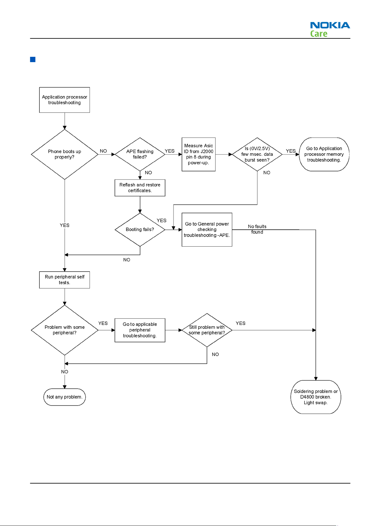
Application processor troubleshooting
Troubleshooting flow
Issue 1 COMPANY CONFIDENTIAL Page 3 –17
Copyright © 2009 Nokia. All rights reserved.
Page 64

Application processor memory troubleshooting
Troubleshooting flow
RX-51
BB Troubleshooting
Page 3 –18 COMPANY CONFIDENTIAL Issue 1
Copyright © 2009 Nokia. All rights reserved.
Page 65

RX-51
BB Troubleshooting
Display module troubleshooting
General instructions for display troubleshooting
The first step is to verify with a working display that the fault is not on the display module itself. The display
module cannot be repaired.
The second step is to check that the engine is working normally. This can be done by connecting the phone
to a docking station and starting Phoenix service software. With the help of Phoenix read the phone
information to check that also the application engine is functioning normally (you should be able to read the
APE ID).
After these checks proceed to the display troubleshooting flowcharts. Use the Display Test tool in Phoenix to
find the detailed fault mode.
Pixel defects
Table 10 Display module troubleshooting cases
Display blank There is no image on the display. The display looks
the same when the phone is on as it does when the
phone is off. The backlight can be on in some cases.
Image on the display not correct Image on the display can be corrupted or a part of
the image can be missing. If a part of the image is
missing, change the display module. If the image is
otherwise corrupted, follow the appropriate
troubleshooting diagram.
Backlight dim or not working at all Backlight LED components are inside the display
module. Backlight failure can also be in the
connector or in the backlight power source in the
main engine of the phone. Backlight is also
controlled automatically by the ambient light
sensor.
This means that in case the display is working
(image OK), the backlight is faulty.
Visual defects (pixel) Pixel defects can be checked by controlling the
display with Phoenix. Use both colours, black and
white, on a full screen.
The display may have some random pixel defects
that are acceptable for this type of display. The
criteria when pixel defects are regarded as a display
failure, resulting in a replacement of the display, are
presented the following table.
Table 11 Pixel defects
Bright sub-pixels (sometimes called on-pixels or stuck-on) are
characterized by the appearance of bright/colored
pixels in, for example, black full screen picture.
Issue 1 COMPANY CONFIDENTIAL Page 3 –19
Copyright © 2009 Nokia. All rights reserved.
Page 66

RX-51
BB Troubleshooting
Dark sub-pixels (sometimes called off-pixels, stuck-off, or black
pixels) are characterized by the appearance of dark
pixels in white, red, green, or blue full-screen
picture.
Combined sub-pixel defects are characterized by at least two sub-pixels
defects (bright or dim) being closer than 5 mm to
each other.
Temporal sub-pixels (sometimes called blinking defects) exhibit
temporal variations not related to any steady-state
video input. Temporal sub-pixel defects may be
intermittent, exhibit a sudden change of state, or
be flickering.
Table 12 Defects table
Item Bright dot (sub-
pixel) defect
1 Defect counts Not allowed
2 Combined sub-
Not allowed
pixel defect
3 Temporal sub-
Not allowed
pixel defect
Note: Blinking pixels are not allowed in normal operating temperatures and light conditions.
Dark dot (sub-
pixel) defect
Total
Page 3 –20 COMPANY CONFIDENTIAL Issue 1
Copyright © 2009 Nokia. All rights reserved.
Page 67

RX-51
BB Troubleshooting
Accelerometer troubleshooting
Troubleshooting flow
Issue 1 COMPANY CONFIDENTIAL Page 3 –21
Copyright © 2009 Nokia. All rights reserved.
Page 68

Display troubleshooting
Troubleshooting flow
RX-51
BB Troubleshooting
Page 3 –22 COMPANY CONFIDENTIAL Issue 1
Copyright © 2009 Nokia. All rights reserved.
Page 69

RX-51
BB Troubleshooting
Display backlight troubleshooting
Troubleshooting flow
Issue 1 COMPANY CONFIDENTIAL Page 3 –23
Copyright © 2009 Nokia. All rights reserved.
Page 70

Touch screen troubleshooting
Troubleshooting flow
RX-51
BB Troubleshooting
Page 3 –24 COMPANY CONFIDENTIAL Issue 1
Copyright © 2009 Nokia. All rights reserved.
Page 71

RX-51
BB Troubleshooting
Illumination troubleshooting
Qwerty keyboard illumination troubleshooting
Troubleshooting flow
Issue 1 COMPANY CONFIDENTIAL Page 3 –25
Copyright © 2009 Nokia. All rights reserved.
Page 72

RGB LED troubleshooting
Troubleshooting flow
RX-51
BB Troubleshooting
Page 3 –26 COMPANY CONFIDENTIAL Issue 1
Copyright © 2009 Nokia. All rights reserved.
Page 73

RX-51
BB Troubleshooting
Keyboard troubleshooting
Power key troubleshooting
Troubleshooting flow
Issue 1 COMPANY CONFIDENTIAL Page 3 –27
Copyright © 2009 Nokia. All rights reserved.
Page 74

Volume keys troubleshooting
Troubleshooting flow
RX-51
BB Troubleshooting
Page 3 –28 COMPANY CONFIDENTIAL Issue 1
Copyright © 2009 Nokia. All rights reserved.
Page 75

RX-51
BB Troubleshooting
Keyboard troubleshooting
Troubleshooting flow
Issue 1 COMPANY CONFIDENTIAL Page 3 –29
Copyright © 2009 Nokia. All rights reserved.
Page 76

Camera key troubleshooting
Troubleshooting flow
RX-51
BB Troubleshooting
Page 3 –30 COMPANY CONFIDENTIAL Issue 1
Copyright © 2009 Nokia. All rights reserved.
Page 77

RX-51
BB Troubleshooting
Sensors troubleshooting
Slide detection troubleshooting
Troubleshooting flow
Issue 1 COMPANY CONFIDENTIAL Page 3 –31
Copyright © 2009 Nokia. All rights reserved.
Page 78

Camera cover troubleshooting
Troubleshooting flow
RX-51
BB Troubleshooting
Page 3 –32 COMPANY CONFIDENTIAL Issue 1
Copyright © 2009 Nokia. All rights reserved.
Page 79

RX-51
BB Troubleshooting
Battery cover detection troubleshooting
Troubleshooting flow
Issue 1 COMPANY CONFIDENTIAL Page 3 –33
Copyright © 2009 Nokia. All rights reserved.
Page 80

Proximity sensor troubleshooting
Troubleshooting flow
RX-51
BB Troubleshooting
Page 3 –34 COMPANY CONFIDENTIAL Issue 1
Copyright © 2009 Nokia. All rights reserved.
Page 81

RX-51
BB Troubleshooting
Audio troubleshooting
Audio troubleshooting test instructions
Single-ended external earpiece and differential internal earpiece outputs can be measured either with a
single-ended or a differential probe.
When measuring with a single-ended probe each output is measured against the ground.
Internal handsfree output is measured using a current probe, if a special low-pass filter designed for
measuring a digital amplifier is not available. Note also that when using a current probe, the input signal
frequency must be set to 2 kHz.
The input signal for each loop test can be either single-ended or differential. Exception to this is a digital
microphone which needs input signal from an external sound source (laptop speaker) to playback, eg. 1 kHz
sine wave from 5 cm distance.
Required equipment
The following equipment is needed for the tests:
•
Oscilloscope
•
Function generator (sine waveform)
•
Current probe (Internal handsfree DPMA output measurement)
•
Phoenix service software
•
Battery voltage 3.7V
•
Sound source (laptop speaker or B&K type 4231 calibrator)
Test procedure
Audio can be tested using the Phoenix audio routings option. Three different audio loop paths can be
activated:
•
External headset mic to earpiece
•
External headset mic to IHF mono
•
Internal digital microphone to headset
Each audio loop sets routing from the specified input to the specified output enabling a quick in-out test.
Loop path gains are fixed and they cannot be changed using Phoenix. Correct pins and signals for each test
are presented in the following table.
Phoenix audio loop tests and test results
The results presented in the table apply when no accessory is connected and battery voltage is set to 3.7V.
Earpiece, internal microphone and speaker are in place during measurement. Applying a headset accessory
during measurement causes a significant drop in measured quantities.
The gain values presented in the table apply for a differential output vs. single-ended/differential input.
Loop test Input
terminal
External
headset
mic to
earpiece
HS_MIC &
GND
Output
terminal
EAR 1 &
GND
EAR 0 &
GND
Path gain
[dB]
(fixed)
0 300 1.35 300
Input
voltage
[mVp-p]
Output DC
level [V]
Output
voltage
[mVp-p]
Issue 1 COMPANY CONFIDENTIAL Page 3 –35
Copyright © 2009 Nokia. All rights reserved.
Page 82

RX-51
BB Troubleshooting
Loop test Input
terminal
External
headset
mic to IHF
mono
Internal
digital
micropho
ne to
headset
HS_MIC &
GND
Acoustica
l Input,
1kHz sine
wave
Output
terminal
L4855 &
L4856
L4857 &
L4858
HS_L &
GND
HS_R &
GND
Path gain
[dB]
(fixed)
10 200 630
NA 94 dBSPL 70
Input
voltage
[mVp-p]
Output DC
level [V]
Output
voltage
[mVp-p]
Page 3 –36 COMPANY CONFIDENTIAL Issue 1
Copyright © 2009 Nokia. All rights reserved.
Page 83

RX-51
BB Troubleshooting
External earpiece troubleshooting
Troubleshooting flow
Issue 1 COMPANY CONFIDENTIAL Page 3 –37
Copyright © 2009 Nokia. All rights reserved.
Page 84

AIC34 troubleshooting
Troubleshooting flow
RX-51
BB Troubleshooting
Page 3 –38 COMPANY CONFIDENTIAL Issue 1
Copyright © 2009 Nokia. All rights reserved.
Page 85

RX-51
BB Troubleshooting
External microphone troubleshooting
Troubleshooting flow
Issue 1 COMPANY CONFIDENTIAL Page 3 –39
Copyright © 2009 Nokia. All rights reserved.
Page 86

Internal earpiece troubleshooting
Troubleshooting flow
RX-51
BB Troubleshooting
Page 3 –40 COMPANY CONFIDENTIAL Issue 1
Copyright © 2009 Nokia. All rights reserved.
Page 87

RX-51
BB Troubleshooting
Internal handsfree speaker troubleshooting
Troubleshooting flow
Issue 1 COMPANY CONFIDENTIAL Page 3 –41
Copyright © 2009 Nokia. All rights reserved.
Page 88

Internal microphone troubleshooting
Troubleshooting flow
RX-51
BB Troubleshooting
Page 3 –42 COMPANY CONFIDENTIAL Issue 1
Copyright © 2009 Nokia. All rights reserved.
Page 89

RX-51
BB Troubleshooting
Vibra troubleshooting
Troubleshooting flow
Issue 1 COMPANY CONFIDENTIAL Page 3 –43
Copyright © 2009 Nokia. All rights reserved.
Page 90

RX-51
BB Troubleshooting
ALS technical description and troubleshooting
Ambient Light Sensor
Ambient Light Sensor
Figure 11 Ambient Light Sensor
Ambient Light Sensor consists of the following components:
•
Ambient Light Sensor (ALS)
ALS is a digital I2C interface component, having two channels with different spectral sensitivities. When
combined, the component responds to illuminance similar as human eye.
•
Vdd Filtering capacitor C1530
Ambient Light Sensor information is used to control keypad and display brightness of the phone.
Keyboard backlight is turned OFF when it is not needed. Display brightness is dimmed when environment
lighting is dark.
Ambient Light Sensor is calibrated in production and can be re-tuned in service points though not
recommended unless calibration coefficient are lost for some reason
ALS troubleshooting
Context
Functionality check:
Steps
1. Connect phone to Phoenix and set the phone (e.g. on the table) so that the amount of ambient light seen
by ALS is as stable as possible.
2. Start Phoenix
3. Choose File -> Scan product
4. Choose Testing -> Display Test
5. Open the Lights tab, check Ambient Light Sensor check box, click Read, cover the sensor and click Read
again. When covered, Luminance reading should be less than after clicking Read without covering the
sensor.
Page 3 –44 COMPANY CONFIDENTIAL Issue 1
Copyright © 2009 Nokia. All rights reserved.
Page 91

RX-51
BB Troubleshooting
6. If component doesn’t give any reading or reading doesn’t change when sensor is/is not covered, replace
the part.
Note: After replacing the ALS. If calibration values of the new sensor are lost or for some other
reason, ALS re-tuning is required (see instructions later in this document).
When doing the ALS calibration procedure, it is required to have a reference phone, which includes
calibrated ALS. ALS re-tuning instructions show why the reference phone is needed.
Re-tuning ALS
Steps
1. Connect reference phone to Phoenix and set the phone (e.g. on the table) so that the amount of ambient
light seen by ALS is as stable as possible.
2. Start Phoenix.
3. Choose File→Scan Product.
Issue 1 COMPANY CONFIDENTIAL Page 3 –45
Copyright © 2009 Nokia. All rights reserved.
Page 92

BB Troubleshooting
4. Choose Tuning -> Ambient Light Sensor Calibration. You should see the following window:
RX-51
5. Read AD-count values for Channel 0 and Channel 1 by click Read button and write them down.
6. Repeat 1-5 for the phone to be calibrated and make sure the phone to be calibrated is located in the
same place as reference phone was when luminance reading was taken.
7. Calculate co-efficient from reference phone and phone to be calibrated AD-count values by division: Coefficient = AD-count(reference phone) / AD-count(phone to be calibrated), write down the calculated coefficient values.
8. -> Iterate by changing Channel 0 and Channel 1 (reference level) values (remove cross from ‘Use default
values only’). After writing some value to Channel 0 and Channel 1 (reference value), calibrate button
must be pressed. Stop iterating when Co-efficient is equal to Co-efficient calculated in step 7. Note that
decimal numbers should be used in the iteration in order to achieve enough precision (e.g. 200.2455)
9. After having same Co-efficient value in “Co-efficient” textbox as the calculated value, make sure that
ambient light values (read using Testing → Display Test → “Luminance” textbox) are almost the same
in reference phone and calibrated phone. Remember that illuminance readings for reference and
calibrated phones must be done in the same ambient light conditions. If illuminance values differs a lot
(difference max. +- 10%), repeat whole ALS re-tuning procedure.
10. To end the calibration, click Close.
Bluetooth and FM radio troubleshooting
Introduction to Bluetooth/FM radio troubleshooting
Bluetooth/WLAN antenna
The BT RF signal is routed from BTFMRDS2.2 through the WLAN module to the shared WLAN/BT antenna in
the phone's B-cover. Check the antenna pin contacts with Bluetooth/WLAN antenna.
Page 3 –46 COMPANY CONFIDENTIAL Issue 1
Copyright © 2009 Nokia. All rights reserved.
Page 93

RX-51
BB Troubleshooting
Figure 12 Bluetooth/WLAN antenna
Introduction to Bluetooth/FM radio troubleshooting
The Bluetooth and FM radio are combined in the same ASIC, so both features are checked when
troubleshooting.
The following problems can occur with the Bluetooth and FM radio hardware:
Symptom Problem Repair solution
Unable to switch on Bluetooth on
phone user interface
Able to send data file to another
Bluetooth device, but unable to
hear audio through functional
Bluetooth headset
Able to switch on Bluetooth on
phone user interface, but unable
to detect other Bluetooth devices
Able to turn on FM radio and
Bluetooth on phone user
interface, but unable to detect
local FM radio stations with Nokia
headset inserted
Able to perform scans to detect
local FM radio stations with
functional Nokia headset
inserted, but unable to hear FM
audio through headset
Open circuit solder joints or
component failure of BTH/FM
ASIC/module BB ASICs or SMD
components
Open circuit solder joints or
component failure of BTH/FM
ASIC/module BB ASICs
Open circuit solder joints or
antenna pins not making
contact with Bluetooth/WLAN
antenna
Open circuit solder joints or
detached component in FM
antenna circuit
Check antenna pin contacts with
Bluetooth/WLAN antenna
Open circuit solder joints or
detached component in FM
audio path between Bluetooth/
FM ASIC and headset
Replacement of Bluetooth/
FM ASIC/module
Replacement of Bluetooth/
FM ASIC/module
Repair or replace Bluetooth/
WLAN antenna
Repair components or
replace Bluetooth/WLAN
antenna module
Repair of FM audio circuit
Users may experience the following problems resulting in functional phones being returned to the repair
centre:
Issue 1 COMPANY CONFIDENTIAL Page 3 –47
Copyright © 2009 Nokia. All rights reserved.
Page 94

BB Troubleshooting
Symptom Problem Repair solution
RX-51
Bluetooth feature does not
operate as desired with another
Bluetooth device
Poor FM radio reception (unable
to detect many radio stations)
Bluetooth Profile implemented
in Bluetooth accessory not
supported in Nokia phone
Nokia headset not being used Use Nokia headset
Use Bluetooth accessory with
Bluetooth profiles supported
by phone
Test coverage
The tests listed in the table below should be performed to verify whether the Bluetooth and FM receiver and
transmitter are functional. The use of Self Tests are described in section
Test Test Coverage Repair solution
Blueooth Self Test: ST_LPRF_IF_TEST Bluetooth-FM ASIC UART interface
(controls Bluetooth and FM
receiver and transmitter)
Bluetooth Self Test:
ST_BT_WAKEUP_TEST
Bluetooth Self Test:
ST_LPRF_AUDIO_LINES_TEST
Bluetooth Functional Test: BER test
with BT-Box or functional test with
other Bluetooth device
Bluetooth ASIC interrupt control
interface
Bluetooth ASIC PCM interface Replacement of Bluetooth/FM
Bluetooth antenna circuit Repair of Bluetooth antenna
BT and FM Self Tests in Phoenix
Replacement of Bluetooth/FM
ASIC (or repair of phone BB)
Replacement of Bluetooth/FM
ASIC (or repair of phone BB)
ASIC (or repair of phone BB)
circuit (including RF filter or
WLAN switch if fitted)
FM Radio Self Test: ST_RADIO_TEST FM Radio I2C interface Replacement of Bluetooth/FM
ASIC (or repair of phone BB)
FM Radio Functional Test: Perform
scan for local radio stations and
check station list displayed on
phone
FM Radio Functional Test: Listen to
local radio station
The self tests run from Phoenix software are used for fault diagnosis.
If Phoenix software is not available the functional tests with phone accessories are sufficient to verify the
functionality Bluetooth and FM radio receiver and transmitter.
FM receiver antenna circuit Repair of FM antenna circuit
(between BTHFM ASIC and
headset connector)
FM receiver audio circuit Repair of FM receiver audio
circuit (between BTHFM ASIC
and headset connector)
Page 3 –48 COMPANY CONFIDENTIAL Issue 1
Copyright © 2009 Nokia. All rights reserved.
Page 95

RX-51
BB Troubleshooting
Bluetooth/FM radio component layout and test points
Figure 13 BT/FM component layout
The Bluetooth antenna is product specific (antenna integrated into phone B cover). On phones with WLAN,
the Bluetooth RF signal is routed through a WLAN front-end module and a shared Bluetooth / WLAN antenna
is used. The FM RF signal is routed through a product specific FM antenna matching circuit to the phone
headset connector. The FM radio audio signal is routed to the headset connector through the BB ASIC shared
by the phone audio functions.
Bluetooth BER test
Prerequisites
JBT-9, or SB-6 Bluetooth test box (BT-box) is required to perform a BER test. If a BT-box not available Bluetooth
functionality can be checked by transferring a file to another Bluetooth phone.
Steps
1. Connect data cable to phone.
2. Start
3. Choose File → Scan Product.
4. Choose Testing → Bluetooth LOCALS .
5. Locate the BT-box serial number (12 digits) found in the type label on the back of the JBT-9, or SB-6
6. In the Bluetooth
7. Place the BT-box near (within 10 cm) of the phone and click Start BER Test.
Phoenix
Bluetooth test box.
service software.
LOCALS
Address
line.
window, write the 12-digit serial number on the
Counterpart BT Device
Issue 1 COMPANY CONFIDENTIAL Page 3 –49
Copyright © 2009 Nokia. All rights reserved.
Page 96

BB Troubleshooting
Bluetooth and FM radio self tests in Phoenix
Prerequisites
A flash adapter (or phone data cable) connected to a PC with Phoenix service software is required.
Steps
1. Place the phone in the flash adapter or connect data cable to phone.
2. Start
3. Choose File→Scan Product.
4. From the Mode drop-down menu, set mode to Local.
5. Choose Testing→Self Tests.
Phoenix
service software.
RX-51
6. In the
•
•
•
•
7. To run the tests, click Start.
Self Tests
ST_LPRF_IF_TEST
ST_LPRF_AUDIO_LINES_TEST
ST_BT_WAKEUP_TEST
ST_RADIO_TEST
window check the following Bluetooth and FM radio related tests:
Figure 14 Bluetooth and FM radio self tests in
Page 3 –50 COMPANY CONFIDENTIAL Issue 1
Copyright © 2009 Nokia. All rights reserved.
Phoenix
Page 97

RX-51
BB Troubleshooting
Bluetooth troubleshooting
Troubleshooting flow
Issue 1 COMPANY CONFIDENTIAL Page 3 –51
Copyright © 2009 Nokia. All rights reserved.
Page 98

FM radio troubleshooting
Troubleshooting flow
RX-51
BB Troubleshooting
Page 3 –52 COMPANY CONFIDENTIAL Issue 1
Copyright © 2009 Nokia. All rights reserved.
Page 99

RX-51
BB Troubleshooting
FM radio testing
Steps
1. Set signal generator parameters:
•
FM modulation on
•
Frequency 100MHz
•
FM deviation 22kHz
•
Modulation frequency 1kHz
•
RF level should be varied during the test to obtain good audio signal quality
•
Connect suitable antenna to signal generator
Note: You may alternately use a known good FM radio broadcast as a test signal.
2. Attach the Nokia headset to the phone’s AV connector.
3. Use Scroll button to autotune to the radio frequency.
4. Set volume to suitable level.
5. Check audio quality with a headset.
GPS troubleshooting
GPS layout and basic test points
The GPS components are located on the top side of the PWB. Satellite signals are picked up by the GPS antenna
in the B-cover. The signal is then routed through a filter before being processed by the GPS5350 receiver ASIC.
Issue 1 COMPANY CONFIDENTIAL Page 3 –53
Copyright © 2009 Nokia. All rights reserved.
Page 100

RX-51
BB Troubleshooting
Figure 15 GPS layout and basic test points
GPS settings for Phoenix
Quick Test window
This test will perform 3 tests in one: Self test, Oscillator Test and CW Test and will provide a Pass/Fail Response
for each. The HW Self Test confirms basic communication with the GPS ASIC. The oscillator test confirms the
frequency accuracy of the GPS TCXO against the Ref_Clk. The CW Test confirms end-to-end connectivity
between the GPS antenna and the GPS ASIC. It also contains a receive button.
Before this test is performed a known good phone should be tested in order to calibrate the setup. The signal
level of the Signal Generator should be adjusted so a reading of SNR 35 dB is achieved with the reference
unit. A good starting point is to set up the signal generator to -50 dBm.
These checks are part of GPS failure troubleshooting (page 3–57).
Page 3 –54 COMPANY CONFIDENTIAL Issue 1
Copyright © 2009 Nokia. All rights reserved.
 Loading...