

Page 1

Nokia Customer Care
Service Manual
RM-484; RM-485; RM-486 (Nokia N86 8MP;
L3&4)
Mobile Terminal
Part No: (Issue 1)
COMPANY CONFIDENTIAL
Copyright © 2009 Nokia. All rights reserved.
Page 2

Amendment Record Sheet
Amendment Record Sheet
Amendment No Date Inserted By Comments
Issue 1 05/2009 MT
RM-484; RM-485; RM-486
Page ii COMPANY CONFIDENTIAL Issue 1
Copyright © 2009 Nokia. All rights reserved.
Page 3

RM-484; RM-485; RM-486
Copyright
Copyright
Copyright © 2009 Nokia. All rights reserved.
Reproduction, transfer, distribution or storage of part or all of the contents in this document in any form
without the prior written permission of Nokia is prohibited.
Nokia, Nokia Connecting People, and Nokia X and Y are trademarks or registered trademarks of Nokia
Corporation. Other product and company names mentioned herein may be trademarks or tradenames of
their respective owners.
Nokia operates a policy of continuous development. Nokia reserves the right to make changes and
improvements to any of the products described in this document without prior notice.
Under no circumstances shall Nokia be responsible for any loss of data or income or any special, incidental,
consequential or indirect damages howsoever caused.
The contents of this document are provided "as is". Except as required by applicable law, no warranties of
any kind, either express or implied, including, but not limited to, the implied warranties of merchantability
and fitness for a particular purpose, are made in relation to the accuracy, reliability or contents of this
document. Nokia reserves the right to revise this document or withdraw it at any time without prior notice.
The availability of particular products may vary by region.
IMPORTANT
This document is intended for use by qualified service personnel only.
Issue 1 COMPANY CONFIDENTIAL Page iii
Copyright © 2009 Nokia. All rights reserved.
Page 4

RM-484; RM-485; RM-486
Warnings and cautions
Warnings and cautions
Warnings
•
IF THE DEVICE CAN BE INSTALLED IN A VEHICLE, CARE MUST BE TAKEN ON INSTALLATION IN VEHICLES FITTED
WITH ELECTRONIC ENGINE MANAGEMENT SYSTEMS AND ANTI-SKID BRAKING SYSTEMS. UNDER CERTAIN FAULT
CONDITIONS, EMITTED RF ENERGY CAN AFFECT THEIR OPERATION. IF NECESSARY, CONSULT THE VEHICLE DEALER/
MANUFACTURER TO DETERMINE THE IMMUNITY OF VEHICLE ELECTRONIC SYSTEMS TO RF ENERGY.
•
THE PRODUCT MUST NOT BE OPERATED IN AREAS LIKELY TO CONTAIN POTENTIALLY EXPLOSIVE ATMOSPHERES,
FOR EXAMPLE, PETROL STATIONS (SERVICE STATIONS), BLASTING AREAS ETC.
•
OPERATION OF ANY RADIO TRANSMITTING EQUIPMENT, INCLUDING CELLULAR TELEPHONES, MAY INTERFERE
WITH THE FUNCTIONALITY OF INADEQUATELY PROTECTED MEDICAL DEVICES. CONSULT A PHYSICIAN OR THE
MANUFACTURER OF THE MEDICAL DEVICE IF YOU HAVE ANY QUESTIONS. OTHER ELECTRONIC EQUIPMENT MAY
ALSO BE SUBJECT TO INTERFERENCE.
•
BEFORE MAKING ANY TEST CONNECTIONS, MAKE SURE YOU HAVE SWITCHED OFF ALL EQUIPMENT.
Cautions
•
Servicing and alignment must be undertaken by qualified personnel only.
•
Ensure all work is carried out at an anti-static workstation and that an anti-static wrist strap is worn.
•
Ensure solder, wire, or foreign matter does not enter the telephone as damage may result.
•
Use only approved components as specified in the parts list.
•
Ensure all components, modules, screws and insulators are correctly re-fitted after servicing and
alignment.
•
Ensure all cables and wires are repositioned correctly.
•
Never test a mobile phone WCDMA transmitter with full Tx power, if there is no possibility to perform the
measurements in a good performance RF-shielded room. Even low power WCDMA transmitters may disturb
nearby WCDMA networks and cause problems to 3G cellular phone communication in a wide area.
•
During testing never activate the GSM or WCDMA transmitter without a proper antenna load, otherwise
GSM or WCDMA PA may be damaged.
Page iv COMPANY CONFIDENTIAL Issue 1
Copyright © 2009 Nokia. All rights reserved.
Page 5

RM-484; RM-485; RM-486
ESD protection
ESD protection
Nokia requires that service points have sufficient ESD protection (against static electricity) when servicing
the phone.
Any product of which the covers are removed must be handled with ESD protection. The SIM card can be
replaced without ESD protection if the product is otherwise ready for use.
To replace the covers ESD protection must be applied.
All electronic parts of the product are susceptible to ESD. Resistors, too, can be damaged by static electricity
discharge.
All ESD sensitive parts must be packed in metallized protective bags during shipping and handling outside
any ESD Protected Area (EPA).
Every repair action involving opening the product or handling the product components must be done under
ESD protection.
ESD protected spare part packages MUST NOT be opened/closed out of an ESD Protected Area.
For more information and local requirements about ESD protection and ESD Protected Area, contact your local
Nokia After Market Services representative.
Issue 1 COMPANY CONFIDENTIAL Page v
Copyright © 2009 Nokia. All rights reserved.
Page 6

RM-484; RM-485; RM-486
Care and maintenance
Care and maintenance
This product is of superior design and craftsmanship and should be treated with care. The suggestions below
will help you to fulfil any warranty obligations and to enjoy this product for many years.
•
Keep the phone and all its parts and accessories out of the reach of small children.
•
Keep the phone dry. Precipitation, humidity and all types of liquids or moisture can contain minerals that
will corrode electronic circuits.
•
Do not use or store the phone in dusty, dirty areas. Its moving parts can be damaged.
•
Do not store the phone in hot areas. High temperatures can shorten the life of electronic devices, damage
batteries, and warp or melt certain plastics.
•
Do not store the phone in cold areas. When it warms up (to its normal temperature), moisture can form
inside, which may damage electronic circuit boards.
•
Do not drop, knock or shake the phone. Rough handling can break internal circuit boards.
•
Do not use harsh chemicals, cleaning solvents, or strong detergents to clean the phone.
•
Do not paint the phone. Paint can clog the moving parts and prevent proper operation.
•
Use only the supplied or an approved replacement antenna. Unauthorised antennas, modifications or
attachments could damage the phone and may violate regulations governing radio devices.
All of the above suggestions apply equally to the product, battery, charger or any accessory.
Page vi COMPANY CONFIDENTIAL Issue 1
Copyright © 2009 Nokia. All rights reserved.
Page 7

RM-484; RM-485; RM-486
Company policy
Company policy
Our policy is of continuous development; details of all technical modifications will be included with service
bulletins.
While every endeavour has been made to ensure the accuracy of this document, some errors may exist. If
any errors are found by the reader, NOKIA MOBILE PHONES Business Group should be notified in writing/email.
Please state:
•
Title of the Document + Issue Number/Date of publication
•
Latest Amendment Number (if applicable)
•
Page(s) and/or Figure(s) in error
Please send to:
NOKIA CORPORATION
Nokia Mobile Phones Business Group
Nokia Customer Care
PO Box 86
FIN-24101 SALO
Finland
E-mail: Service.Manuals@nokia.com
Issue 1 COMPANY CONFIDENTIAL Page vii
Copyright © 2009 Nokia. All rights reserved.
Page 8

RM-484; RM-485; RM-486
Battery information
Battery information
Note: A new battery's full performance is achieved only after two or three complete charge and
discharge cycles!
The battery can be charged and discharged hundreds of times but it will eventually wear out. When the
operating time (talk-time and standby time) is noticeably shorter than normal, it is time to buy a new battery.
Use only batteries approved by the phone manufacturer and recharge the battery only with the chargers
approved by the manufacturer. Unplug the charger when not in use. Do not leave the battery connected to
a charger for longer than a week, since overcharging may shorten its lifetime. If left unused a fully charged
battery will discharge itself over time.
Temperature extremes can affect the ability of your battery to charge.
For good operation times with Li-Ion batteries, discharge the battery from time to time by leaving the product
switched on until it turns itself off (or by using the battery discharge facility of any approved accessory
available for the product). Do not attempt to discharge the battery by any other means.
Use the battery only for its intended purpose.
Never use any charger or battery which is damaged.
Do not short-circuit the battery. Accidental short-circuiting can occur when a metallic object (coin, clip or
pen) causes direct connection of the + and - terminals of the battery (metal strips on the battery) for example
when you carry a spare battery in your pocket or purse. Short-circuiting the terminals may damage the battery
or the connecting object.
Leaving the battery in hot or cold places, such as in a closed car in summer or winter conditions, will reduce
the capacity and lifetime of the battery. Always try to keep the battery between 15°C and 25°C (59°F and 77°
F). A phone with a hot or cold battery may temporarily not work, even when the battery is fully charged.
Batteries' performance is particularly limited in temperatures well below freezing.
Do not dispose of batteries in a fire!
Dispose of batteries according to local regulations (e.g. recycling). Do not dispose as household waste.
Page viii COMPANY CONFIDENTIAL Issue 1
Copyright © 2009 Nokia. All rights reserved.
Page 9

RM-484; RM-485; RM-486
Nokia N86 8MP; L3&4 Service Manual Structure
Nokia N86 8MP; L3&4 Service Manual Structure
1 General Information
2 Service Tools and Service Concepts
3 BB Troubleshooting
4 RF Troubleshooting
5 Camera Module Troubleshooting
6 FMTx 2.1 Technical Description
7 FMTx 2.1 Troubleshooting
8 System Module and User Interface
Glossary
Issue 1 COMPANY CONFIDENTIAL Page ix
Copyright © 2009 Nokia. All rights reserved.
Page 10

RM-484; RM-485; RM-486
Nokia N86 8MP; L3&4 Service Manual Structure
(This page left intentionally blank.)
Page x COMPANY CONFIDENTIAL Issue 1
Copyright © 2009 Nokia. All rights reserved.
Page 11

Nokia Customer Care
1 — General Information
Issue 1 COMPANY CONFIDENTIAL Page 1 –1
Copyright © 2009 Nokia. All rights reserved.
Page 12

RM-484; RM-485; RM-486
General Information
(This page left intentionally blank.)
Page 1 –2 COMPANY CONFIDENTIAL Issue 1
Copyright © 2009 Nokia. All rights reserved.
Page 13

RM-484; RM-485; RM-486
General Information
Table of Contents
Product selection....................................................................................................................................................1–5
Product features and sales package.....................................................................................................................1–6
Mobile enhancements............................................................................................................................................1–9
Technical Specifications...................................................................................................................................... 1–10
Transceiver general specifications ............................................................................................................... 1–10
Main RF characteristics for GSM850/900/1800/1900 and WCDMA VIII/II/I phones ................................. 1–10
Main RF characteristics for GSM850/900/1800/1900 and WCDMA V/II/I phones ..................................... 1–12
Battery endurance.......................................................................................................................................... 1–13
Environmental conditions ............................................................................................................................. 1–13
List of Tables
Table 1 Audio..........................................................................................................................................................1–9
Table 2 Car...............................................................................................................................................................1–9
Table 3 Data ............................................................................................................................................................1–9
Table 4 Messaging............................................................................................................................................... 1–10
Table 5 Power...................................................................................................................................................... 1–10
List of Figures
Figure 1 View of RM-484........................................................................................................................................1–5
Issue 1 COMPANY CONFIDENTIAL Page 1 –3
Copyright © 2009 Nokia. All rights reserved.
Page 14

RM-484; RM-485; RM-486
General Information
(This page left intentionally blank.)
Page 1 –4 COMPANY CONFIDENTIAL Issue 1
Copyright © 2009 Nokia. All rights reserved.
Page 15
RM-484; RM-485; RM-486
General Information
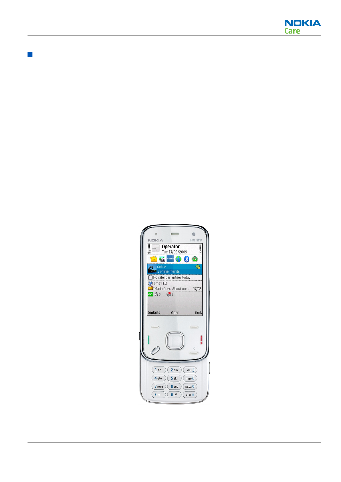
Product selection
RM-484 is a quad-band handportable multimedia computer, supporting EGSM850/900/1800/1900, with
WCDMA VIII (900)/ II (1900)/ I (2100) HSDPA and WLAN. RM-485 supports EGSM850/900/1800/1900, with
WCDMA V (850)/ II (1900)/ I (2100) HSDPA and WLAN. RM-486 supports EGSM850/900/1800/1900 and WCDMA
V (850)/ II (1900)/ I (2100) HSDPA, but does not support WLAN.
The device is a 3GPP Release 5 terminal supporting WCDMA/HSDPA, EGPRS and GPRS data bearers. For WCDMA
HSDPA the maximum bit rate is up to 3.6 Mbps for downlink and 384 kbps for uplink with simultaneous CS
speech or CS video (max. 64 kbps).
For 2G and 2.5G networks the device is a Class A EGPRS DTM MSC 11 which means a maximum download speed
of up to 296 kbit/s with EGPRS, and up to 107 kbit/s with GPRS.
According to GSM standard 05.05 it responds to class 4 (max. 2W) in GSM 850 and EGSM 900 class 1 (1W) in
DCS 1800 and class 1 in PCS 1900. The device supports EGPRS (EDGE) class B, Bluetooth 2.0 EDR standard.
The device supports two-way video calls with two integrated cameras, one on the front and one on the back.
The device is an MMS (Multimedia Messaging Service) enabled multimedia computer with a large Active Matrix
OLED (AM OLED) 2.6’’ QVGA (240 x 320 pixels) display capable of displaying 16 million colours and an integrated
8 Megapixel auto focus camera. The MMS implementation follows the OMA MMS standard release 1.2. The
Browser is a highly advanced internet browser also capable of viewing operator domain XHTML Mobile Profile
(MP) content.
The device uses Symbian 9.3 operating system and supports MIDP Java 2.0 & CLDC1.1, providing a good
platform for compelling 3rd party applications.
Figure 1 View of RM-484
Issue 1 COMPANY CONFIDENTIAL Page 1 –5
Copyright © 2009 Nokia. All rights reserved.
Page 16

Product features and sales package
Imaging
Main camera:
•
Sensor: 8 megapixel (3280 x 2464 pixels)
•
Carl Zeiss Optics: Tessar™ lens
•
F number/Aperture: F2.4/3.2/4.8
•
Focal length: 4.6 mm
35 mm (35 mm equivalent)
•
Focus range: 10 cm ~ infinity
•
Macro focus distance: 10-50 cm
•
Shutter speed: Mechanical shutter 1/1000~1/4 s
•
Kickstand
Secondary camera:
•
Sensor: CIF (352 x 288 pixels)
•
F number/Aperture: F2.4/3.2/4.8
•
Focal length: 43 mm (35mm equivalent)
•
Focus range: 10 cm ~ infinity
Video:
•
Video resolution: VGA at 30 fps
•
Audio recording: AAC (AMR for MMS)
•
Video stabilization
•
Video clip length: 60 min
•
Video file format: .mp4 (default), .3gp (for MMS)
•
White balance: automatic, sunny, cloudy, incandescent, fluorescent
•
Scene: Auto, Night
•
Colour tone: normal, sepia, B&W, vivid, negative
•
Zoom (digital): up to 8x
Photo:
•
Still image resolutions: up to 8 megapixel: 3280 x 2464
•
Still image file format: JPEG/EXIF
•
Auto focus
•
Auto exposure: center weighted AE
•
Automatic motion blur reduction
•
Image orientation: automatic
•
Exposure compensation: +2 ~ -2EV at 0.5 step
•
White balance: automatic, sunny, cloudy, incandescent, fluorescent
•
Scene: auto, sports, portrait, close-up, landscape, night, panorama, user defined
•
Colour tone: normal, sepia, B&W, vivid, negative
•
Zoom (digital): up to 20x
Other camera features:
RM-484; RM-485; RM-486
General Information
Page 1 –6 COMPANY CONFIDENTIAL Issue 1
Copyright © 2009 Nokia. All rights reserved.
Page 17

RM-484; RM-485; RM-486
General Information
•
LED flash and recording indicator
•
Front camera, CIF (352 x 288) sensor
Edit
•
On device Photo editor and Video editor (manual & automatic)
View
•
2.6” QVGA (240 x 320 pixels) 16 million colour AM OLED display with wide viewing angle and ambient light
detector - used to optimize display and keypad backlight brightness and power consumption
•
Slideshow from Gallery
Share
•
Nokia XpressShare - share effortlessly from Gallery or after capture via E-mail, Bluetooth or MMS
•
Direct connection to TV via cable or WLAN (UPnP)
•
Video call and video sharing support (WCDMA services)
•
Online Album : Image/Video uploading from Gallery
Print
•
Nokia XpressPrint – direct printing via USB (PictBridge), Bluetooth (BPP), and WLAN (UPnP), from memory
card or via online printing
Store
•
Nokia XpressTransfer – easy to transfer and organize photos and video between your device and a
compatible PC
•
Nokia Lifeblog (mobile & PC)
Music
•
Digital music player: supports MP3/ AAC/ eAAC/ eAAC+/ WMA with playlists, equalizer and album art, WAV
and Midi.
•
Synchronise music with Microsoft Windows Media Player 10 & 11
•
One click CD ripping, converting and transferring music to your device using Nokia Music Manager
•
Stereo FM radio (88.1 – 107.9 MHz) with RDS and Visual Radio™ support
•
Stereo speakers
•
Integrated FM transmitter (88.1 – 107.9 MHz) (not in RM-486)
•
Integrated handsfree speaker
•
Nokia Music Headset AD-54/HS-83 (Black/Silver) or AD-54/HS-44 (White/Silver)
Media
•
Full-screen video playback to view downloaded, streamed or recorded video clips
•
Supported video formats: MPEG-4 , H.264/AVC, H.263/3GPP, RealVideo 8/9/10
Productivity
Messaging:
•
E-mail (SMTP, IMAP4, POP3), MMS, SMS
Office applications:
Issue 1 COMPANY CONFIDENTIAL Page 1 –7
Copyright © 2009 Nokia. All rights reserved.
Page 18

RM-484; RM-485; RM-486
General Information
•
Viewing of email attachments – .doc, .xls, .ppt, . pdf
PIM:
•
Contacts, calendar, to-do, notes, recorder, calculator, clock, converter
Synchronization:
•
Local/Remote (using SyncML)
•
Data: Calendar, Contacts, To-do, Notes, E-mail
•
PC Applications: Microsoft Outlook (98, 2000, 2002, 2003), Outlook Express, Lotus Organizer (5.0, 6.0),
Lotus Notes (5.0, 6.0)
Call management:
•
Call logs, speed dial, voice dialling (with SIND) and voice commands
•
Nokia Push to Talk (PoC)
Connectivity
•
Assisted GPS (A-GPS)
•
WLAN - IEEE802.11 g/b with UPnP support (not in RM-486)
•
Micro USB type B interface with USB 2.0 full speed
•
Bluetooth wireless technology 2.0 + EDR
•
MicroSDHC memory card - support up to 16GB (hot swappable)
•
Nokia 3.5 mm AV connector
Add-on software framework
•
Symbian 9.3 OS
•
Nokia Series 60, 3rd edition, feature pack 3
•
Java: MIDP2.0
•
C++ and Java SDKs
Additional technical specifications
•
City compass to support easy pedestrian routing and guidance
•
Vibrating alert
•
3GPP Rel 5 WCDMA , Rel 4 EGSM compliant
•
Speech codecs supported in WCDMA: AMR
•
Speech codecs supported in GSM: FR AMR/HR AMR/EFR/FR/HR
•
WCDMA HSDPA with simultaneous voice and packet data (PS max speed DL/UL= 3.6Mbps/384kbps, CS max
speed 64kbps)
•
Dual Transfer Mode (DTM) support for simultaneous voice and packet data connection in GSM/EDGE
networks. Simple class A, multi slot class 11, max speed DL/UL: 118.4/118.4kbits/s
•
EGPRS class B, multi slot class 32, (5 Rx + 3 Tx / Max Sum 6), max speed DL/UL= 296 / 177.6 kbits/s
•
GPRS class B, multi slot class 32 (5 Rx + 3 Tx / Max Sum 6), max speed DL/UL= 107 / 64.2 kbits/s
Sales package
•
Transceiver RM-484, RM-485 or RM-486
•
Charger (AC-10)
•
Battery (BL-5K)
Page 1 –8 COMPANY CONFIDENTIAL Issue 1
Copyright © 2009 Nokia. All rights reserved.
Page 19
RM-484; RM-485; RM-486
General Information
•
Nokia Music Headset AD-54/HS-83 (Black/Silver) or AD-54/HS-44 (White/Silver)
•
Connectivity cable (CA-101)
Mobile enhancements
Table 1 Audio
Enhancement Type
Music headset HS-44 with AD-54 3.5mm stereo plug
Basic headset HS-41
Stereo headset WH-800
Bluetooth headset BH-101
BH-201
BH-208
BH-214
BH-600
BH-604
BH-800
BH-801
BH-803
BH-804
BH-900
BH-903
Mini speaker MD-6
Table 2 Car
Enhancement Type
Nokia Universal Holder CR-99
Car kit Nokia 616
Multimedia car kit CK-7W
Table 3 Data
Enhancement Type
Connectivity cable CA-101
Video connectivity cable CA-75U
Nokia Mobile TV Receiver SU-33W
Issue 1 COMPANY CONFIDENTIAL Page 1 –9
Copyright © 2009 Nokia. All rights reserved.
Page 20
Enhancement Type
MicroSD card MU-28, 512 MB MicroSD Card
MU-22, 1 GB MicroSD Card
MU-37, 2 GB MicroSD Card
MU-41, 4 GB MicroSD Card
MU-43, 8 GB MicroSD Card
MU-44, 16 GB MicroSDHC Card
Table 4 Messaging
Enhancement Type
Wireless keyboard SU-8W
Table 5 Power
RM-484; RM-485; RM-486
General Information
Enhancement Type
Battery 1200mAh Li-ion BL-5K
Travel charger AC-10
Technical Specifications
Transceiver general specifications
Unit Dimensions (L x W x T)
Transceiver with BL-5K
1200mAh li-ion battery
back
(mm)
103.4 x 51.4 x 16.5 149 84
Weight (g)
Volume (cm3)
Main RF characteristics for GSM850/900/1800/1900 and WCDMA VIII/II/I phones
Parameter Unit
Cellular system GSM850, EGSM900, GSM1800/1900, WCDMA VIII
(900), WCDMA II (1900) and WCDMA I (2100)
Rx frequency band GSM850: 869 - 894 MHz
EGSM900: 925 - 960 MHz
GSM1800: 1805 - 1880 MHz
GSM1900: 1930 - 1990 MHz
WCDMA VIII (900): 925- 960 MHz
WCDMA II (1900): 1930-1990MHz
WCDMA I (2100): 2110 - 2170 MHz
Page 1 –10 COMPANY CONFIDENTIAL Issue 1
Copyright © 2009 Nokia. All rights reserved.
Page 21
RM-484; RM-485; RM-486
General Information
Parameter Unit
Tx frequency band GSM850: 824 - 849 MHz
EGSM900: 880 - 915 MHz
GSM1800: 1710 - 1785 MHz
GSM1900: 1850 - 1910 MHz
WCDMA VIII (900): 880 - 915 MHz
WCDMA II (1900): 1850-1910MHz
WCDMA I (2100): 1920 - 1980 MHz
Output power GSM850: +5 ...+33dBm/3.2mW ... 2W
GSM900: +5 … +33dBm/3.2mW … 2W
GSM1800: +0 … +30dBm/1.0mW … 1W
GSM1900: +0 … +30dBm/1.0mW … 1W
WCDMA VIII (900): -50 ... +24 dBm/0.01μW ...
251.2mW
WCDMA II (1900): -50 ... +24dBm/0.01µW ...
251.2mW
WCDMA I (2100): -50 ... +24 dBm/0.01μW ...
251.2mW
EDGE output power EDGE850: +5 … +29dBm/3.2mW … 794mW
EDGE900: +5 … +29dBm/3.2mW … 794mW
EDGE1800: +0 … +26dBm/1.0mW … 400mW
EDGE1900:+0 … +26dBm/1.0mW … 400mW
Number of RF channels GSM850: 124
GSM900: 174
GSM1800: 374
GSM1900: 299
WCDMA VIII (900): 152
WCDMA II (1900): 289
WCDMA I (2100): 277
Channel spacing 200 kHz (WCDMA II 100/200 kHz)
Number of Tx power levels GSM850: 15
GSM900: 15
GSM1800: 16
GSM1900: 16
WCDMA VIII (900): 75
WCDMA II (1900): 75
WCDMA I (2100): 75
Issue 1 COMPANY CONFIDENTIAL Page 1 –11
Copyright © 2009 Nokia. All rights reserved.
Page 22
RM-484; RM-485; RM-486
General Information
Main RF characteristics for GSM850/900/1800/1900 and WCDMA V/II/I phones
Parameter Unit
Cellular system GSM850, EGSM900, GSM1800/1900, WCDMA V (850), WCDMA II
(1900) and WCDMA I (2100)
Rx frequency band GSM850: 869 - 894MHz
EGSM900: 925 - 960 MHz
GSM1800: 1805 - 1880 MHz
GSM1900: 1930 - 1990 MHz
WCDMA V (850): 869 - 894 MHz
WCDMA II (1900): 1930 - 1990 MHz
WCDMA I (2100): 2110 - 2170 MHz
Tx frequency band GSM850: 824 - 849MHz
EGSM900: 880 - 915 MHz
GSM1800: 1710 - 1785 MHz
GSM1900: 1850 - 1910 MHz
WCDMA V (850): 824 - 849 MHz
WCDMA II (1900): 1850 - 1910 MHz
WCDMA I (2100): 1920 - 1980 MHz
Output power GSM850: +5 ...+33dBm/3.2mW ... 2W
GSM900: +5 … +33dBm/3.2mW … 2W
GSM1800: +0 … +30dBm/1.0mW … 1W
GSM1900: +0 … +30dBm/1.0mW … 1W
WCDMA V (850): -50 ... +24 dBm/0.01μW ... 251.2mW
WCDMA II (1900): -50 ... +24 dBm/0.01μW ... 251.2mW
WCDMA I (2100): -50 ... +24 dBm/0.01μW ... 251.2mW
EDGE output power EDGE850: +5 … +29dBm/3.2mW … 794mW
EDGE900: +5 … +29dBm/3.2mW … 794mW
EDGE1800: +0 … +26dBm/1.0mW … 400mW
EDGE1900:+0 … +26dBm/1.0mW … 400mW
Page 1 –12 COMPANY CONFIDENTIAL Issue 1
Copyright © 2009 Nokia. All rights reserved.
Page 23
RM-484; RM-485; RM-486
General Information
Parameter Unit
Number of RF channels GSM850: 124
GSM900: 174
GSM1800: 374
GSM1900: 299
WCDMA V (850): 108
WCDMA II (1900): 289
WCDMA I (2100): 277
Channel spacing 200 kHz (WCDMA V and II 100/200 kHz)
Number of Tx power levels GSM850: 15
GSM900: 15
GSM1800: 16
GSM1900: 16
WCDMA V (850): 75
WCDMA II (1900): 75
WCDMA I (2100): 75
Battery endurance
Battery Capacity (mAh) Talk time Stand-by
BL-5K 1200 Up to 4.5 h (WCDMA) &
6.9 h (GSM)
Charging times
AC-10
1h 30 min
Environmental conditions
Environmental
condition
Ambient temperature Notes
Up to 363 h (WCDMA) &
363 h (GSM)
Normal operation
Reduced performance
Intermittent or no
operation
No operation or
storage
Charging allowed
Issue 1 COMPANY CONFIDENTIAL Page 1 –13
-10 oC ... +55 oC
55 oC ... +70 oC
-40 oC ... -15 oC and +70 oC ... +85oC
<-40 oC and >+85 oC
-15 oC ... +55 oC
Copyright © 2009 Nokia. All rights reserved.
Specifications fulfilled
Operational only for short periods
Operation not guaranteed but an
attempt to operate will not damage
the phone
No storage. An attempt to operate
may cause permanent damage
Page 24
RM-484; RM-485; RM-486
General Information
Environmental
condition
Long term storage
conditions
Humidity and water
resistance
Ambient temperature Notes
0 oC ... +85 oC
Relative humidity range is 5 to 95%.
Condensed or dripping water may
cause intermittent malfunctions.
Protection against dripping water
has to be implemented in (enclosure)
mechanics.
Continuous dampness will cause
permanent damage to the module.
Page 1 –14 COMPANY CONFIDENTIAL Issue 1
Copyright © 2009 Nokia. All rights reserved.
Page 25

Nokia Customer Care
2 — Service Tools and Service
Concepts
Issue 1 COMPANY CONFIDENTIAL Page 2 –1
Copyright © 2009 Nokia. All rights reserved.
Page 26

RM-484; RM-485; RM-486
Service Tools and Service Concepts
(This page left intentionally blank.)
Page 2 –2 COMPANY CONFIDENTIAL Issue 1
Copyright © 2009 Nokia. All rights reserved.
Page 27

RM-484; RM-485; RM-486
Service Tools and Service Concepts
Table of Contents
Service tools............................................................................................................................................................2–5
Product specific tools........................................................................................................................................2–5
FS-113............................................................................................................................................................2–5
MJ-208 ...........................................................................................................................................................2–5
RJ-230 ............................................................................................................................................................2–6
SA-131 ...........................................................................................................................................................2–6
SA-154 ...........................................................................................................................................................2–6
SS-182............................................................................................................................................................2–6
Cables..................................................................................................................................................................2–6
CA-101 ...........................................................................................................................................................2–7
CA-31D ...........................................................................................................................................................2–7
CA-35S............................................................................................................................................................2–7
CA-56RS..........................................................................................................................................................2–7
PCS-1..............................................................................................................................................................2–8
XCS-1..............................................................................................................................................................2–8
XCS-4..............................................................................................................................................................2–8
Service concepts .....................................................................................................................................................2–9
POS (Point of Sale) flash concept .....................................................................................................................2–9
Flash concept with FPS-10............................................................................................................................. 2–10
CU-4 flash concept with FPS-10..................................................................................................................... 2–11
Flash concept with FPS-10 and SB-6............................................................................................................. 2–12
Flash concept with SS-46 and CA-89DS ........................................................................................................ 2–13
Flash concept with SS-62 and CA-89DS ........................................................................................................ 2–14
Flash concept with FPS-10, SS-62 and SB-6 ................................................................................................. 2–15
Flash concept with FPS-10, SS-62 and SB-7 ................................................................................................. 2–16
Module jig service concept............................................................................................................................ 2–17
Module jig service concept with SB-6........................................................................................................... 2–18
RF testing concept with RF coupler .............................................................................................................. 2–19
Service concept for RF testing and RF/BB tuning........................................................................................ 2–20
List of Figures
Figure 2 POS flash concept ....................................................................................................................................2–9
Figure 3 Basic flash concept with FPS-10.......................................................................................................... 2–10
Figure 4 CU-4 flash concept with FPS-10........................................................................................................... 2–11
Figure 5 Flash concept with FPS-10 and SB-6................................................................................................... 2–12
Figure 6 Flash concept with SS-46 and CA-89DS .............................................................................................. 2–13
Figure 7 Flash concept with SS-62 and CA-89DS .............................................................................................. 2–14
Figure 8 Flash concept with FPS-10, SS-62 and SB-6 ....................................................................................... 2–15
Figure 9 Flash concept with FPS-10, SB-7 and JBT-9........................................................................................ 2–16
Figure 10 Module jig service concept................................................................................................................ 2–17
Figure 11 Module jig service concept with SB-6............................................................................................... 2–18
Figure 12 RF testing concept with RF coupler.................................................................................................. 2–19
Figure 13 Service concept for RF testing and RF/BB tuning............................................................................ 2–20
Issue 1 COMPANY CONFIDENTIAL Page 2 –3
Copyright © 2009 Nokia. All rights reserved.
Page 28

RM-484; RM-485; RM-486
Service Tools and Service Concepts
(This page left intentionally blank.)
Page 2 –4 COMPANY CONFIDENTIAL Issue 1
Copyright © 2009 Nokia. All rights reserved.
Page 29
RM-484; RM-485; RM-486
Service Tools and Service Concepts
Service tools
Product specific tools
The table below gives a short overview of service devices that can be used for testing, error analysis, and
repair of product RM-484; RM-485; RM-486. For the correct use of the service devices, and the best effort of
workbench setup, please refer to various concepts.
FS-113 Flash adapter
•
provides standardised interface towards Control Unit
•
multiplexing between USB and FBUS media, controlled by VUSB
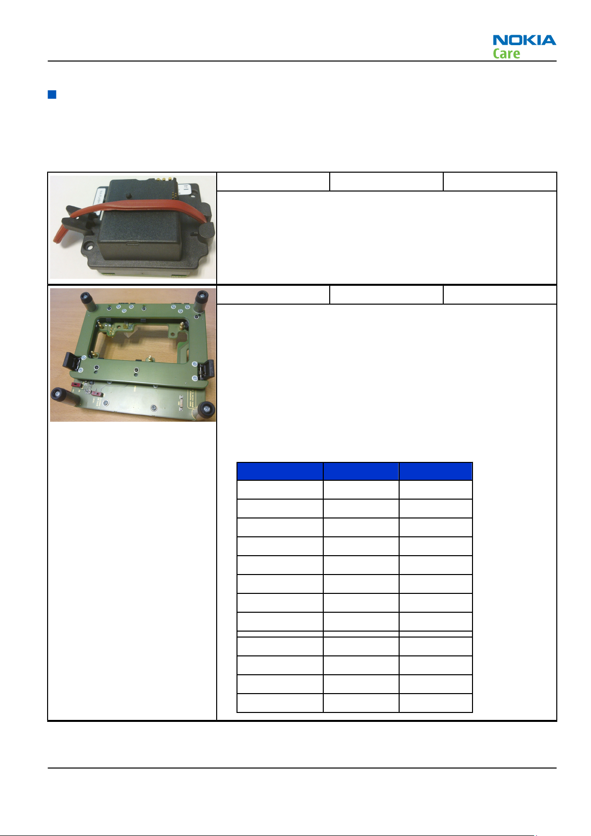
MJ-208 Module jig MJ-208 is meant for component level troubleshooting.
The jig includes RF interface for Bluetooth, WLAN and GPS. In addition,
it has the following features:
•
Provides mechanical interface with the engine module
•
Provides galvanic connection to all needed test pads in module
•
Multiplexing between USB and FBUS media, controlled by Vusb
•
Connector for control unit
•
Access for Audio-, MMC, and USB connectors
•
Module jig attenuation values:
Band F Attenuation
GSM850 TX 824-849 0.4dB
GSM850 RX 869-894 0.4dB
EGSM900 TX 880-915 0.4dB
EGSM900 RX 935-960 0.4dB
GSM1800 TX 1710-1785 0.6dB
GSM1800 RX 1805-1880 0.6dB
GSM1900 TX 1850-1910 0.6dB
GSM1900 RX 1930-1990 0.6dB
WCDMA850 TX 824-849 0.4dB
WCDMA850 RX 869-894 0.4dB
WCDMA1900 TX 1850-1910 0.6dB
WCDMA1900 RX 1930-1990 0.6dB
Issue 1 COMPANY CONFIDENTIAL Page 2 –5
Copyright © 2009 Nokia. All rights reserved.
Page 30
RM-484; RM-485; RM-486
Service Tools and Service Concepts
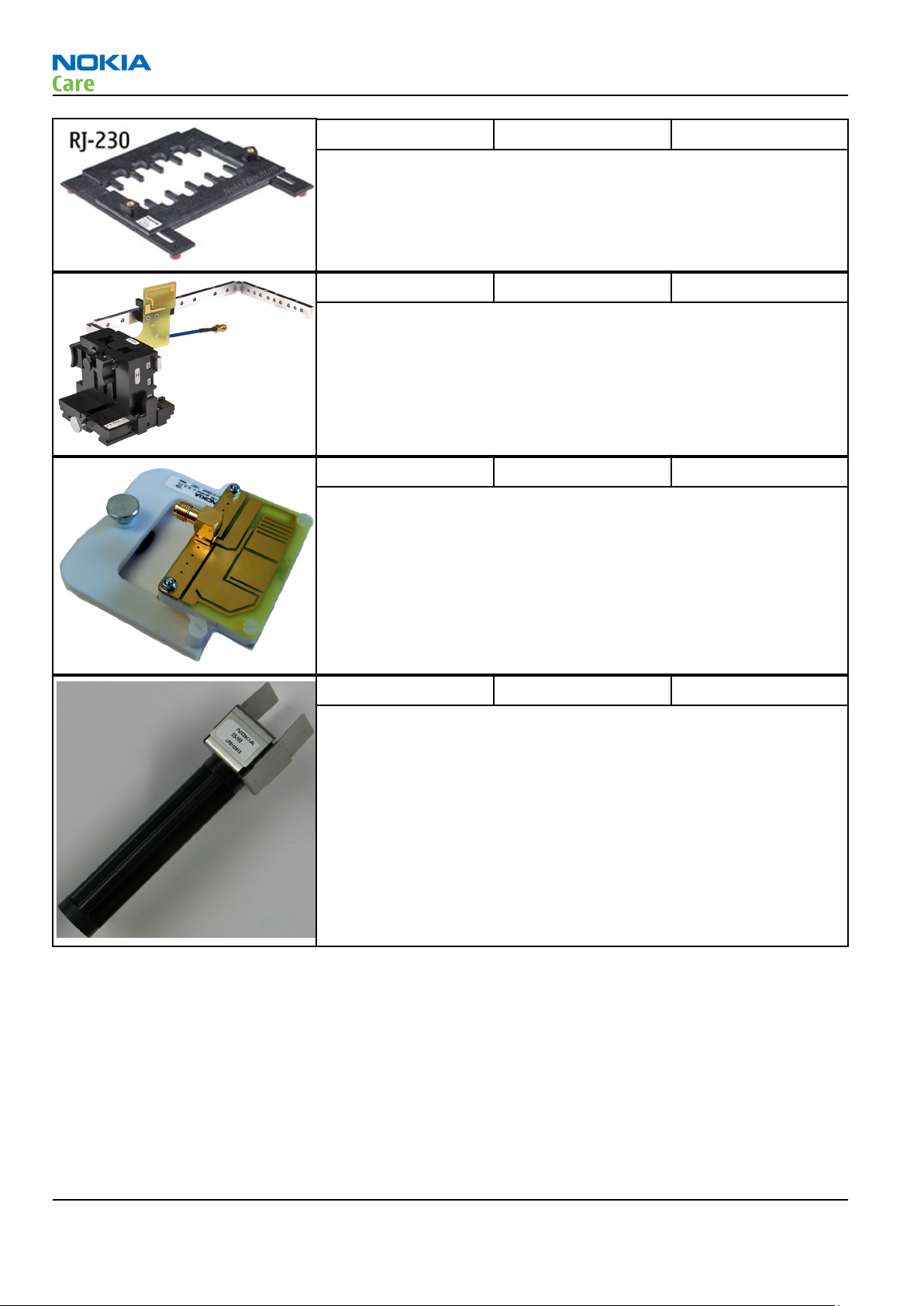
RJ-230 Soldering jig The jig is used for soldering and as a rework jig for the system module.
It is made of lead-free rework compatible material.
SA-131 RF coupler SA-131 is a generic device for GPS testing. It is used together with
SS-62.
SA-154 RF coupler SA-154 is an RF coupler for WCDMA and GSM RF testing. It is used
together with the product-specific flash adapter.
SS-182 Camera removal tool The camera removal tool SS-182 is used to remove/attach a camera
module from/to the camera socket of the phone PWB.
Cables
The table below gives a short overview of service devices that can be used for testing, error analysis, and
repair of product RM-484; RM-485; RM-486. For the correct use of the service devices, and the best effort of
workbench setup, please refer to various concepts.
Page 2 –6 COMPANY CONFIDENTIAL Issue 1
Copyright © 2009 Nokia. All rights reserved.
Page 31
RM-484; RM-485; RM-486
Service Tools and Service Concepts
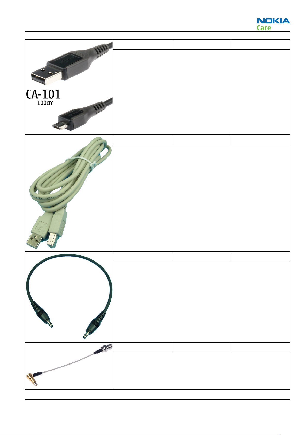
CA-101 Micro USB cable The CA-101 is a USB-to-microUSB data cable that allows connections
between the PC and the phone.
CA-31D USB cable The CA-31D USB cable is used to connect FPS-21 to a PC. It is included
in the FPS-21 sales package.
CA-35S Power cable CA-35S is a power cable for connecting, for example, the FPS-21 flash
prommer to the Point-Of-Sales (POS) flash adapter.
CA-56RS RF cable Small RF cable that is used for RF tuning with product specific module
jig.
Issue 1 COMPANY CONFIDENTIAL Page 2 –7
Copyright © 2009 Nokia. All rights reserved.
Page 32

RM-484; RM-485; RM-486
Service Tools and Service Concepts
PCS-1 Power cable The PCS-1 power cable (DC) is used with a docking station, a module
jig or a control unit to supply a controlled voltage.
XCS-1 Service cable The XCS-1 service cable is used to connect FLS-4S to the POS flash
adapter for supplying a controlled operating voltage and data
connection.
XCS-4 Modular cable XCS-4 is a shielded (one specially shielded conductor) modular cable
for flashing and service purposes.
Page 2 –8 COMPANY CONFIDENTIAL Issue 1
Copyright © 2009 Nokia. All rights reserved.
Page 33

RM-484; RM-485; RM-486
Service Tools and Service Concepts
Service concepts
POS (Point of Sale) flash concept
Figure 2 POS flash concept
Type Description
Product specific tools
BL-5K Battery
Other tools
FLS-5 POS flash dongle
PC with Phoenix service software
Cables
CA-101 USB connectivity cable
Issue 1 COMPANY CONFIDENTIAL Page 2 –9
Copyright © 2009 Nokia. All rights reserved.
Page 34

Flash concept with FPS-10
RM-484; RM-485; RM-486
Service Tools and Service Concepts
Figure 3 Basic flash concept with FPS-10
Type Description
Product specific devices
FS-113 Flash adapter
Other devices
FPS-10 Flash prommer box
PKD-1/PK-1 SW security device
SS-46 Interface adapter
PC with Phoenix service software
Cables
XCS-4 Modular cable
CA-35S Power cable
USB cable
Page 2 –10 COMPANY CONFIDENTIAL Issue 1
Copyright © 2009 Nokia. All rights reserved.
Page 35

RM-484; RM-485; RM-486
Service Tools and Service Concepts
CU-4 flash concept with FPS-10
Figure 4 CU-4 flash concept with FPS-10
Type Description
Product specific devices
FS-113 Flash adapter
Other devices
CU-4 Control unit
FPS-10 Flash prommer box
PKD-1/PK-1 SW security device
SS-62 Flash adapter base
SX-4 Smart card
PC with Phoenix service software
Cables
PCS-1 Power cable
XCS-4 Modular cable
Standard USB cable
USB cable
Issue 1 COMPANY CONFIDENTIAL Page 2 –11
Copyright © 2009 Nokia. All rights reserved.
Page 36

Flash concept with FPS-10 and SB-6
RM-484; RM-485; RM-486
Service Tools and Service Concepts
Figure 5 Flash concept with FPS-10 and SB-6
Type Description
Product specific tools
FS-113 Flash adapter
Other tools
FPS-10 Flash prommer box
PKD-1/PK-1 SW security device
SS-46 Interface adapter
SB-6 Bluetooth test and interface box
PC with Phoenix service software
Cables
XCS-4 Modular cable
CA-35S Power cable
Page 2 –12 COMPANY CONFIDENTIAL Issue 1
Copyright © 2009 Nokia. All rights reserved.
Page 37

RM-484; RM-485; RM-486
Service Tools and Service Concepts
Type Description
USB cable
Flash concept with SS-46 and CA-89DS
Figure 6 Flash concept with SS-46 and CA-89DS
Type Description
Product specific tools
FS-113 Flash adapter
Other tools
FLS-5 Flash device
SS-46 Interface adapter
PC with Phoenix service software
Cables
CA-89DS Cable
Issue 1 COMPANY CONFIDENTIAL Page 2 –13
Copyright © 2009 Nokia. All rights reserved.
Page 38

Flash concept with SS-62 and CA-89DS
RM-484; RM-485; RM-486
Service Tools and Service Concepts
Figure 7 Flash concept with SS-62 and CA-89DS
Type Description
Product specific tools
FS-113 Flash adapter
Other tools
CU-4 Control unit
FLS-5 Flash device
SS-62 Flash adapter base
PC with Phoenix service software
Cables
CA-89DS Cable
PCS-1 Power cable
USB cable
Page 2 –14 COMPANY CONFIDENTIAL Issue 1
Copyright © 2009 Nokia. All rights reserved.
Page 39

RM-484; RM-485; RM-486
Service Tools and Service Concepts
Flash concept with FPS-10, SS-62 and SB-6
Figure 8 Flash concept with FPS-10, SS-62 and SB-6
Type Description
Product specific tools
FS-113 Flash adapter
Other tools
CU-4 Control unit
FPS-10 Flash prommer box
PKD-1/PK-1 SW security device
SS-62 Flash adapter base
SB-6 Bluetooth test and interface box
SX-4 Smart card
PC with Phoenix service software
Cables
XCS-4 Modular cable
PCS-1 Power cable
Issue 1 COMPANY CONFIDENTIAL Page 2 –15
Copyright © 2009 Nokia. All rights reserved.
Page 40

Type Description
USB cable
Flash concept with FPS-10, SS-62 and SB-7
RM-484; RM-485; RM-486
Service Tools and Service Concepts
Figure 9 Flash concept with FPS-10, SB-7 and JBT-9
Type Description
Product specific tools
FS-113 Flash adapter
Other tools
CU-4 Control unit
FPS-10 Flash prommer box
PKD-1/PK-1 SW security device
SB-7 WLAN test box
SS-62 Flash adapter base
SX-4 Smart card
PC with Phoenix service software
Cables
XCS-4 Modular cable
PCS-1 Power cable
Page 2 –16 COMPANY CONFIDENTIAL Issue 1
Copyright © 2009 Nokia. All rights reserved.
Page 41

RM-484; RM-485; RM-486
Service Tools and Service Concepts
Type Description
USB cable
Module jig service concept
Figure 10 Module jig service concept
Type Description
Phone specific devices
MJ-208 Module jig
Other devices
CU-4 Control unit
FPS-10 Flash prommer box
PK-1 SW security device
SX-4 Smart card
PC with VPOS and Phoenix service software
Measurement equipment
Cables
PCS-1 DC power cable
XCS-4 Modular cable
Issue 1 COMPANY CONFIDENTIAL Page 2 –17
Copyright © 2009 Nokia. All rights reserved.
Page 42

Type Description
CA-56RS RF cable
CA-568RS RF tuning cable
USB cable
GPIB control cable
Module jig service concept with SB-6
RM-484; RM-485; RM-486
Service Tools and Service Concepts
Figure 11 Module jig service concept with SB-6
Type Description
Product specific tools
MJ-208 Module jig
Other tools
CU-4 Control unit
FPS-10 Flash prommer box
Page 2 –18 COMPANY CONFIDENTIAL Issue 1
Copyright © 2009 Nokia. All rights reserved.
Page 43

RM-484; RM-485; RM-486
Service Tools and Service Concepts
Type Description
SB-6 Bluetooth test and interface box
PKD-1 SW security device
SX-4 Smart card
Measurement equipment
PC with Phoenix service software
Cables
PCS-1 DC power cable
XCS-4 Modular cable
CA-56RS RF cable
CA-56RS RF tuning cable
GPIB control cable
USB cable
RF testing concept with RF coupler
Figure 12 RF testing concept with RF coupler
Type Description
Product specific devices
FS-113 Flash adapter
Issue 1 COMPANY CONFIDENTIAL Page 2 –19
Copyright © 2009 Nokia. All rights reserved.
Page 44
Type Description
SA-154 RF coupler
Other devices
CU-4 Control unit
SX-4 Smart card
FPS-10 Flash prommer box
PKD-1/PK-1 SW security device
SS-62 Flash adapter base
Measurement equipment
PC with Phoenix service software
Cables
PCS-1 Power cable
XCS-4 Modular cable
RM-484; RM-485; RM-486
Service Tools and Service Concepts
CA-56RS RF cable
GPIB control cable
USB cable
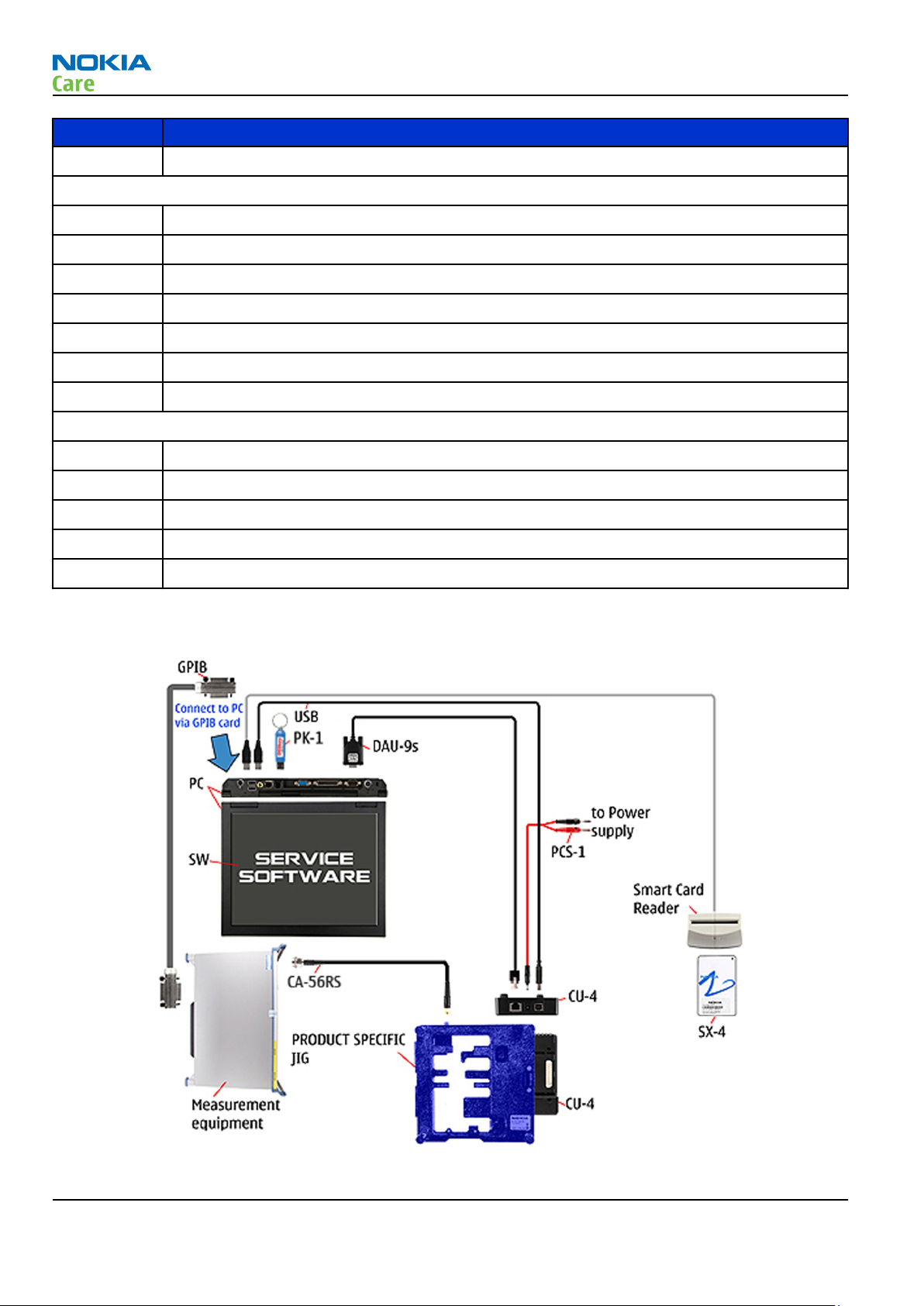
Service concept for RF testing and RF/BB tuning
Figure 13 Service concept for RF testing and RF/BB tuning
Page 2 –20 COMPANY CONFIDENTIAL Issue 1
Copyright © 2009 Nokia. All rights reserved.
Page 45

RM-484; RM-485; RM-486
Service Tools and Service Concepts
Type Description
Product specific devices
MJ-208 Module jig
Other devices
CU-4 Control unit
PK-1/PKD-1 SW security device
SX-4 Smart card
Measurement equipment
Smart card reader
PC with Phoenix service software
Cables
DAU-9S MBUS cable
PCS-1 DC power cable
CA-56RS RF cable
CA-56RS RF tuning cable
GPIB control cable
USB cable
Issue 1 COMPANY CONFIDENTIAL Page 2 –21
Copyright © 2009 Nokia. All rights reserved.
Page 46

RM-484; RM-485; RM-486
Service Tools and Service Concepts
(This page left intentionally blank.)
Page 2 –22 COMPANY CONFIDENTIAL Issue 1
Copyright © 2009 Nokia. All rights reserved.
Page 47

Nokia Customer Care
3 — BB Troubleshooting
Issue 1 COMPANY CONFIDENTIAL Page 3 –1
Copyright © 2009 Nokia. All rights reserved.
Page 48

RM-484; RM-485; RM-486
BB Troubleshooting
(This page left intentionally blank.)
Page 3 –2 COMPANY CONFIDENTIAL Issue 1
Copyright © 2009 Nokia. All rights reserved.
Page 49

RM-484; RM-485; RM-486
BB Troubleshooting
Table of Contents
Baseband main troubleshooting..........................................................................................................................3–5
General power checking ........................................................................................................................................3–7
Backup battery troubleshooting...........................................................................................................................3–8
Dead or jammed device troubleshooting......................................................................................................... 3–10
Keyboard troubleshooting ................................................................................................................................. 3–11
Hall sensor troubleshooting............................................................................................................................... 3–13
TV- out troubleshooting ..................................................................................................................................... 3–14
General power checking troubleshooting ........................................................................................................ 3–15
USB troubleshooting ........................................................................................................................................... 3–16
SIM card troubleshooting ................................................................................................................................... 3–17
MicroSD card troubleshooting............................................................................................................................ 3–18
Combo memory troubleshooting ...................................................................................................................... 3–20
Flash programming troubleshooting................................................................................................................ 3–21
USB charging troubleshooting........................................................................................................................... 3–24
Clocking troubleshooting ................................................................................................................................... 3–25
Power key troubleshooting................................................................................................................................ 3–26
User interface troubleshooting.......................................................................................................................... 3–27
Accelerometer troubleshooting......................................................................................................................... 3–28
Magnetometer troubleshooting ........................................................................................................................ 3–30
Display Troubleshooting..................................................................................................................................... 3–33
Display Troubleshooting................................................................................................................................ 3–33
Illumination troubleshooting ....................................................................................................................... 3–35
LED driver troubleshooting ........................................................................................................................... 3–38
I/O expander troubleshooting ...................................................................................................................... 3–39
Audio Troubleshooting....................................................................................................................................... 3–39
Audio troubleshooting test instructions...................................................................................................... 3–39
External earpiece troubleshooting............................................................................................................... 3–43
DAC33 troubleshooting.................................................................................................................................. 3–44
External microphone troubleshooting ........................................................................................................ 3–45
Internal earpiece troubleshooting .............................................................................................................. 3–46
Internal handsfree speaker troubleshooting ............................................................................................. 3–47
Internal microphone troubleshooting ........................................................................................................ 3–48
Vibra troubleshooting.................................................................................................................................... 3–49
ALS Technical Description and Troubleshooting.............................................................................................. 3–50
Ambient Light Sensor..................................................................................................................................... 3–50
ALS troubleshooting....................................................................................................................................... 3–50
Re-tuning ALS.................................................................................................................................................. 3–51
Bluetooth and FM Radio Troubleshooting........................................................................................................ 3–52
Introduction to Bluetooth/FM radio troubleshooting................................................................................ 3–52
Bluetooth BER test.......................................................................................................................................... 3–55
Bluetooth and FM radio self tests in Phoenix.............................................................................................. 3–55
Bluetooth troubleshooting ........................................................................................................................... 3–57
FM radio troubleshooting.............................................................................................................................. 3–57
FM radio testing.............................................................................................................................................. 3–59
GPS Troubleshooting........................................................................................................................................... 3–59
GPS layout and basic test points................................................................................................................... 3–59
GPS Settings for Phoenix ............................................................................................................................... 3–60
GPS control................................................................................................................................................. 3–60
Quick Test window.................................................................................................................................... 3–61
GPS failure troubleshooting.......................................................................................................................... 3–63
Issue 1 COMPANY CONFIDENTIAL Page 3 –3
Copyright © 2009 Nokia. All rights reserved.
Page 50

RM-484; RM-485; RM-486
BB Troubleshooting
WLAN Troubleshooting....................................................................................................................................... 3–63
WLAN functional description......................................................................................................................... 3–63
WLAN settings for Phoenix............................................................................................................................ 3–64
WLAN functional tests.................................................................................................................................... 3–66
WLAN auto tuning.......................................................................................................................................... 3–68
List of Figures
Figure 14 Single-ended output waveform of the Ext_in_HP_out measurement when earpiece is
connected .................................................................................................................................................. 3–41
Figure 15 Single-ended output waveform of the Ext_in_IHF_out out loop measurement when speaker
is connected (measured at speaker pads), no filter is used ................................................................. 3–41
Figure 16 Single-ended output waveform of the Ext_in_Ext_out loop........................................................... 3–42
Figure 17 Single-ended output waveform of the Digital_stereo_microphone_in_Ext_out loop.................. 3–42
Figure 18 Ambient Light Sensor ........................................................................................................................ 3–50
Figure 19 Bluetooth/WLAN antenna ................................................................................................................. 3–53
Figure 20 BT/FM component layout .................................................................................................................. 3–55
Figure 21 Bluetooth and FM radio self tests in Phoenix.................................................................................. 3–56
Figure 22 GPS layout and basic test points....................................................................................................... 3–60
Figure 23 GPS Control dialogue box .................................................................................................................. 3–61
Figure 24 GPS Quick Test window ..................................................................................................................... 3–62
Figure 25 WLAN circuitry .................................................................................................................................... 3–64
Figure 26 WLAN auto tune settings................................................................................................................... 3–69
Figure 27 WLAN auto tune results..................................................................................................................... 3–70
Page 3 –4 COMPANY CONFIDENTIAL Issue 1
Copyright © 2009 Nokia. All rights reserved.
Page 51

RM-484; RM-485; RM-486
BB Troubleshooting
Baseband main troubleshooting
Troubleshooting flow
Issue 1 COMPANY CONFIDENTIAL Page 3 –5
Copyright © 2009 Nokia. All rights reserved.
Page 52

RM-484; RM-485; RM-486
BB Troubleshooting
Page 3 –6 COMPANY CONFIDENTIAL Issue 1
Copyright © 2009 Nokia. All rights reserved.
Page 53

RM-484; RM-485; RM-486
BB Troubleshooting
General power checking
Check the following voltages:
Signal
name
VIO_V AVILMA ON ON 1.82 Not used
VBACK AVILMA ON ON 2.5 RTC circuitry
VSIM1 AVILMA ON ON 1.8/3.0 Sim card
VSIM2 AVILMA ON ON 3.0 Digital microphone
VAUX AVILMA OFF OFF 2.78 Accelerometer, Hall
VANA AVILMA ON ON 2.5 Vilma internal
VR1 AVILMA OFF ON 2.5 VCTXO
VRFC AVILMA ON OFF 1.8 RAPIDO converter
VRCP1 AVILMA OFF OFF 4.75 RFmodule RF active
VIO LM3677 ON ON 1.8 Rapido , Betty I/O
VDRAM LM3677 ON ON 1.8 M3 Memory
VCORE TPS62350 ON ON 1.2 Rapido core
VDAC LP3985 3.0 DAC33 On when
Regulator Sleep Idle Nominal
voltage
Main user Notes
switches, 2nd
camera
used
VCAM_1V8 LM3677 OFF OFF 1.8 Julie, LP5952
VCAM_1V3 OFF OFF 1.3 Julie,core
VCAM_2V8 OFF OFF 2.8 Main camera
VSD LP3930 OFF OFF 2.9 SD card On when
used
V_ELVDD TPS65136 OFF OFF 4.6 Falcon OLED Display
V_ELVSS TPS65136 OFF OFF -4.9 Falcon OLED Display
VCORE_WD LP5952 OFF OFF 1.5 White Dwarf Core
VBAT 3.6
VCORE BETTY OFF OFF 1.2 Not used
VDRAM_V AVILMA ON 1.82 Not used
VLED BETTY 6-18 Not used
Issue 1 COMPANY CONFIDENTIAL Page 3 –7
Copyright © 2009 Nokia. All rights reserved.
Page 54
RM-484; RM-485; RM-486
BB Troubleshooting
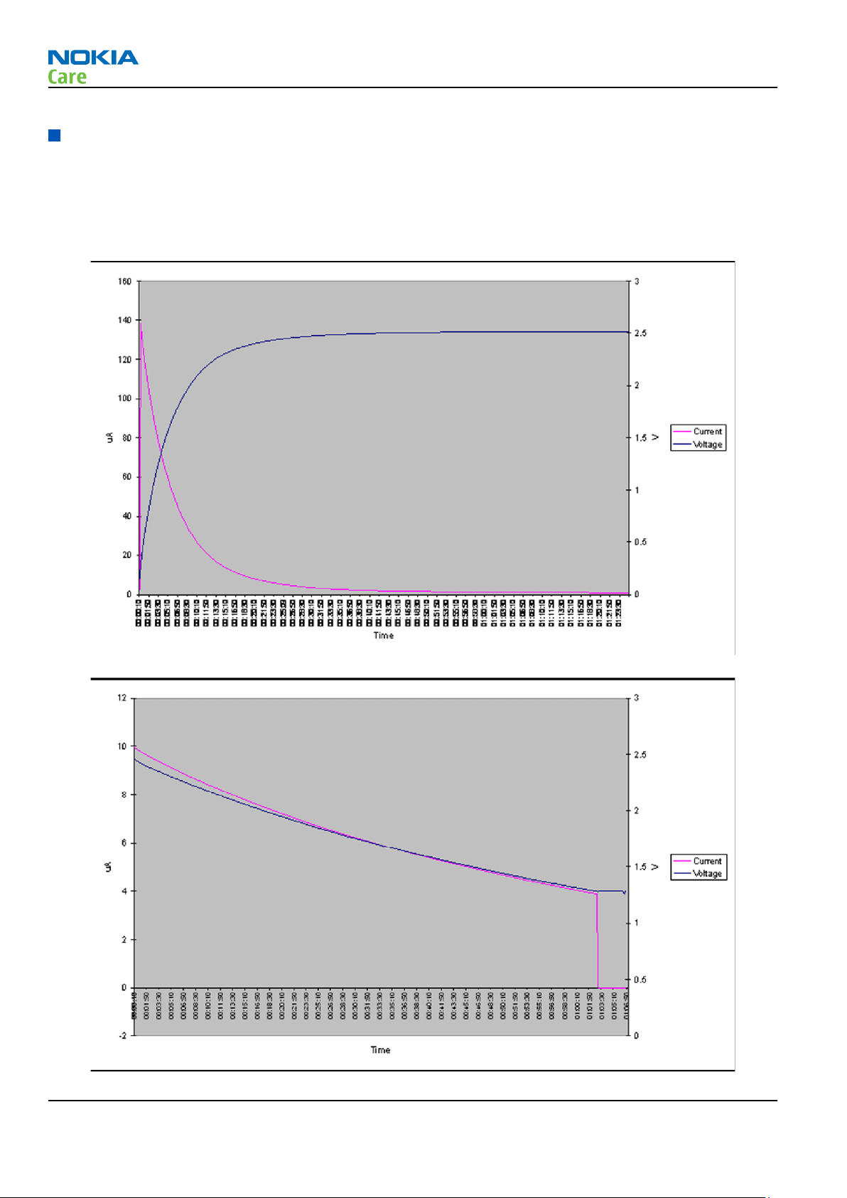
Backup battery troubleshooting
Verify that the backup battery G2200 is empty (U<1V). Switch the phone on. Measure voltage of the battery
when the main battery is connected to the phone and the phone is switched on. Wait a few minutes and
monitor that the backup battery voltage rises. Switch off the phone, disconnect the main battery and monitor
that the voltage of the backup battery decreases. Normal behaviour of the voltage is described in the figures
below:
Page 3 –8 COMPANY CONFIDENTIAL Issue 1
Copyright © 2009 Nokia. All rights reserved.
Page 55

RM-484; RM-485; RM-486
BB Troubleshooting
If the voltage rises and falls quickly, check the back-up battery G2200 contacts for loose soldering or shortcircuit, and repair or change G2200 if necessary. If the voltage stays ~0V, check resistance VBACK against GND.
If there is no shortcircuit, AVILMA N2200 is faulty. Replace N2200.
Issue 1 COMPANY CONFIDENTIAL Page 3 –9
Copyright © 2009 Nokia. All rights reserved.
Page 56
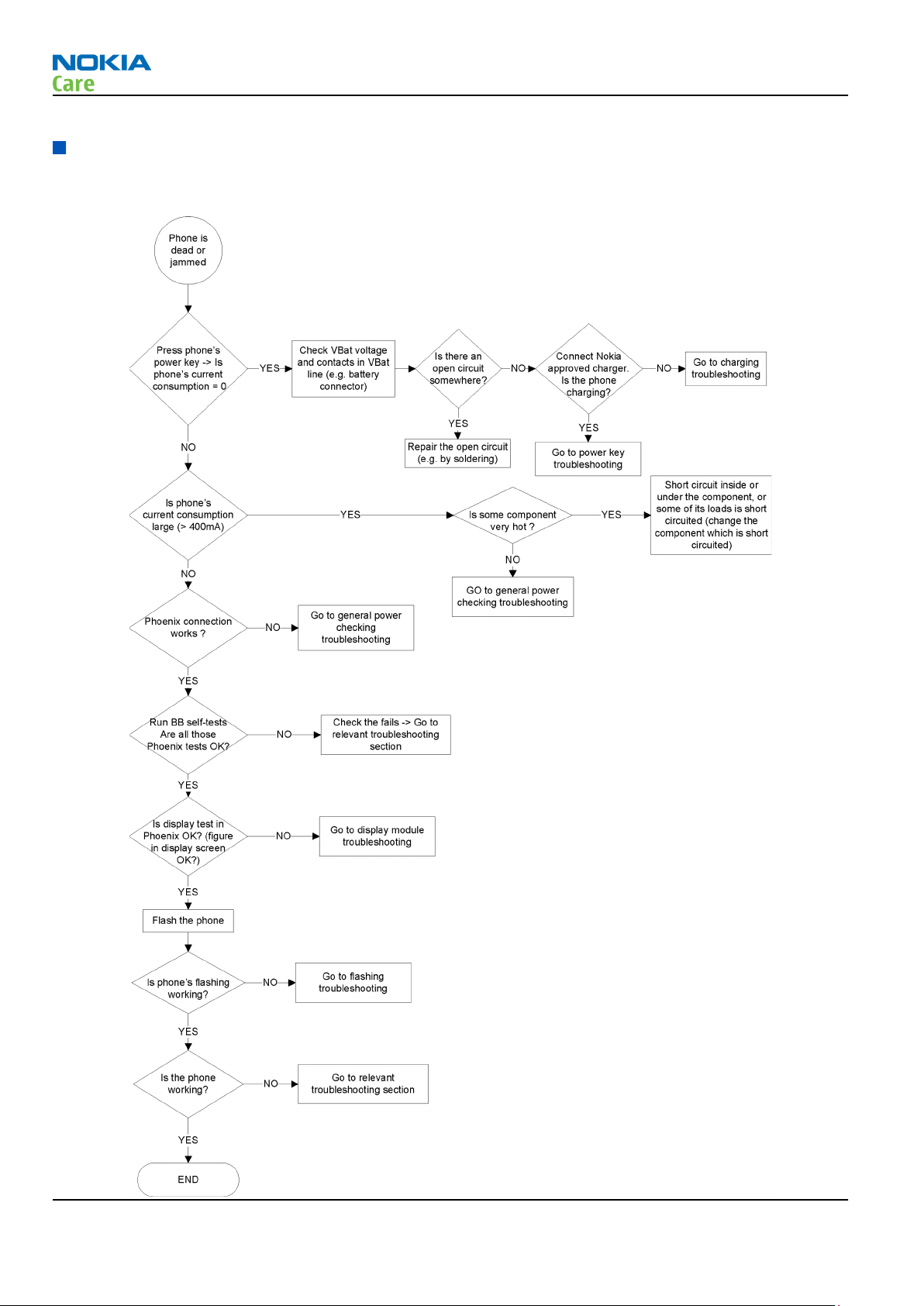
Dead or jammed device troubleshooting
Troubleshooting flow
RM-484; RM-485; RM-486
BB Troubleshooting
Page 3 –10 COMPANY CONFIDENTIAL Issue 1
Copyright © 2009 Nokia. All rights reserved.
Page 57

RM-484; RM-485; RM-486
BB Troubleshooting
Keyboard troubleshooting
Context
There are two possible failure modes in the keyboard module:
1 One or more keys are stuck, so that the key(s) does not react when you press a keydome. This kind of
failure is caused by mechanical reasons (dirt, corrosion).
2 Malfunction of several keys at the same time; this happens when one or more rows or columns are failing
(shortcut or open connection). For a more detailed description of the keyboard and keymatrix, see section
Keyboard.
If the failure mode is not clear, start with the Keyboard Test in
Phoenix
.
Issue 1 COMPANY CONFIDENTIAL Page 3 –11
Copyright © 2009 Nokia. All rights reserved.
Page 58

Troubleshooting flow
RM-484; RM-485; RM-486
BB Troubleshooting
Page 3 –12 COMPANY CONFIDENTIAL Issue 1
Copyright © 2009 Nokia. All rights reserved.
Page 59

RM-484; RM-485; RM-486
BB Troubleshooting
Hall sensor troubleshooting
Troubleshooting flow
Issue 1 COMPANY CONFIDENTIAL Page 3 –13
Copyright © 2009 Nokia. All rights reserved.
Page 60

TV- out troubleshooting
Troubleshooting flow
RM-484; RM-485; RM-486
BB Troubleshooting
Page 3 –14 COMPANY CONFIDENTIAL Issue 1
Copyright © 2009 Nokia. All rights reserved.
Page 61

RM-484; RM-485; RM-486
BB Troubleshooting
General power checking troubleshooting
Troubleshooting flow
Issue 1 COMPANY CONFIDENTIAL Page 3 –15
Copyright © 2009 Nokia. All rights reserved.
Page 62

USB troubleshooting
Troubleshooting flow
RM-484; RM-485; RM-486
BB Troubleshooting
Page 3 –16 COMPANY CONFIDENTIAL Issue 1
Copyright © 2009 Nokia. All rights reserved.
Page 63
RM-484; RM-485; RM-486
BB Troubleshooting
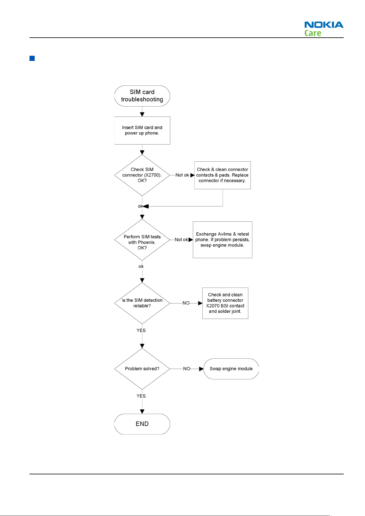
SIM card troubleshooting
Troubleshooting flow
Issue 1 COMPANY CONFIDENTIAL Page 3 –17
Copyright © 2009 Nokia. All rights reserved.
Page 64

MicroSD card troubleshooting
Troubleshooting flow
RM-484; RM-485; RM-486
BB Troubleshooting
Page 3 –18 COMPANY CONFIDENTIAL Issue 1
Copyright © 2009 Nokia. All rights reserved.
Page 65

RM-484; RM-485; RM-486
BB Troubleshooting
Issue 1 COMPANY CONFIDENTIAL Page 3 –19
Copyright © 2009 Nokia. All rights reserved.
Page 66

Combo memory troubleshooting
Troubleshooting flow
RM-484; RM-485; RM-486
BB Troubleshooting
Page 3 –20 COMPANY CONFIDENTIAL Issue 1
Copyright © 2009 Nokia. All rights reserved.
Page 67

RM-484; RM-485; RM-486
BB Troubleshooting
Flash programming troubleshooting
Troubleshooting flow
Issue 1 COMPANY CONFIDENTIAL Page 3 –21
Copyright © 2009 Nokia. All rights reserved.
Page 68

RM-484; RM-485; RM-486
BB Troubleshooting
Page 3 –22 COMPANY CONFIDENTIAL Issue 1
Copyright © 2009 Nokia. All rights reserved.
Page 69

RM-484; RM-485; RM-486
BB Troubleshooting
Issue 1 COMPANY CONFIDENTIAL Page 3 –23
Copyright © 2009 Nokia. All rights reserved.
Page 70

USB charging troubleshooting
Troubleshooting flow
RM-484; RM-485; RM-486
BB Troubleshooting
Page 3 –24 COMPANY CONFIDENTIAL Issue 1
Copyright © 2009 Nokia. All rights reserved.
Page 71

RM-484; RM-485; RM-486
BB Troubleshooting
Clocking troubleshooting
Troubleshooting flow
Issue 1 COMPANY CONFIDENTIAL Page 3 –25
Copyright © 2009 Nokia. All rights reserved.
Page 72

Power key troubleshooting
Troubleshooting flow
RM-484; RM-485; RM-486
BB Troubleshooting
Page 3 –26 COMPANY CONFIDENTIAL Issue 1
Copyright © 2009 Nokia. All rights reserved.
Page 73

RM-484; RM-485; RM-486
BB Troubleshooting
User interface troubleshooting
Troubleshooting flow
Issue 1 COMPANY CONFIDENTIAL Page 3 –27
Copyright © 2009 Nokia. All rights reserved.
Page 74
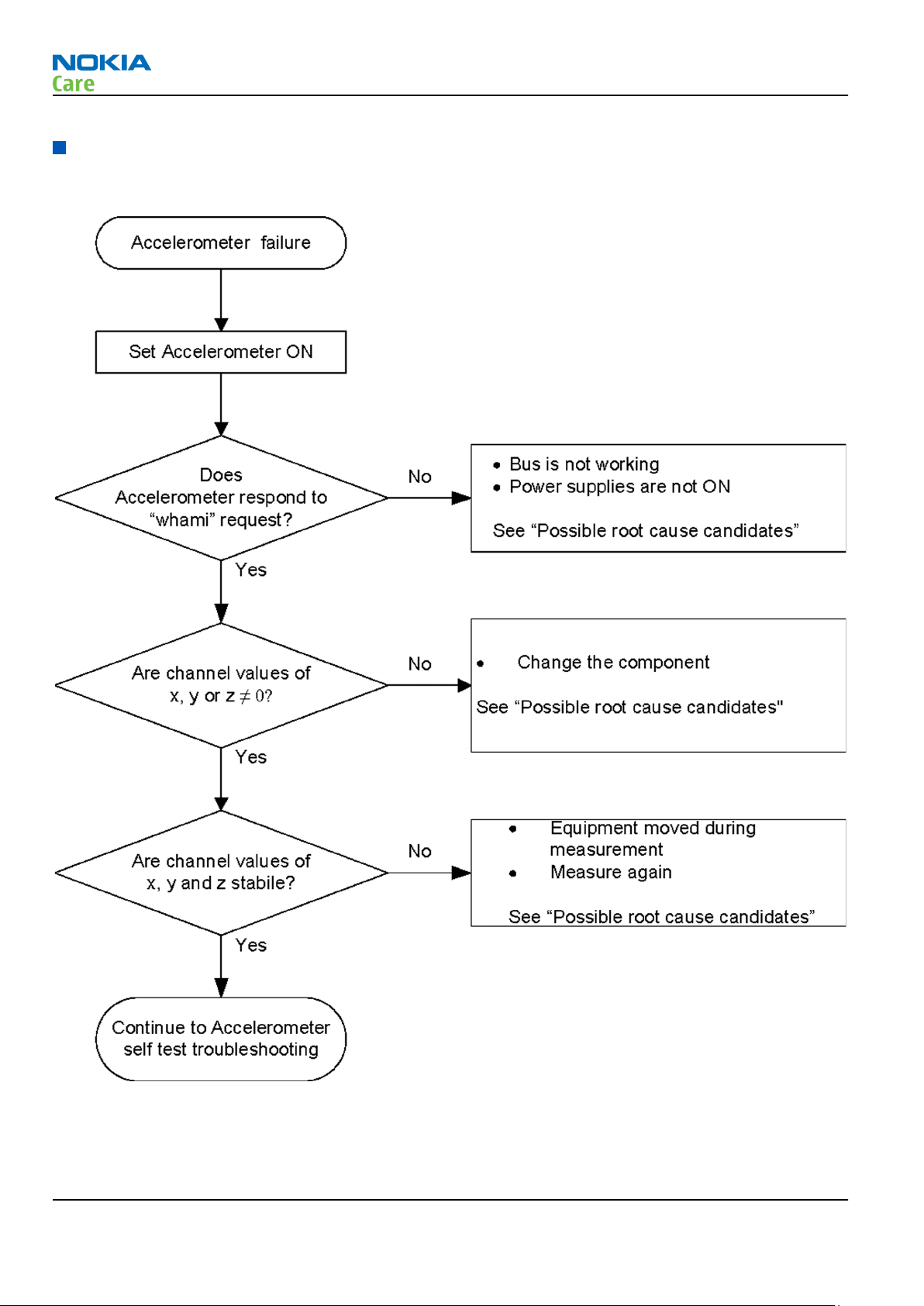
Accelerometer troubleshooting
Accelerometer general troubleshooting
RM-484; RM-485; RM-486
BB Troubleshooting
Page 3 –28 COMPANY CONFIDENTIAL Issue 1
Copyright © 2009 Nokia. All rights reserved.
Page 75
RM-484; RM-485; RM-486
BB Troubleshooting
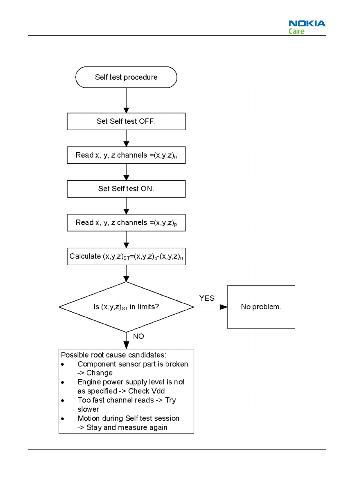
Accelerometer self test troubleshooting
Issue 1 COMPANY CONFIDENTIAL Page 3 –29
Copyright © 2009 Nokia. All rights reserved.
Page 76

Self test limits
•
Values in LSB
•
4605957 (ST, LIS3LV02DQ)
•
2.5V
•
x=(min 180, max 320)
•
y=(min 180, max 320)
•
z=(min 80, max 250)
•
2.8V, not evaluated
•
4605983 (ADI, AD22340)
•
2.5V not evaluated
•
2.8V
•
x=(min 15, max 30)
•
y=(min 15, max 30)
•
z=(min 3, max 15)
•
4605987 (ST, LIS302DL)
•
2.5V not evaluated
•
2.8V
•
x=(min 3, max 16), unsigned
•
y=(min 3, max 16), unsigned
•
z=(min 3, max 16), unsigned
RM-484; RM-485; RM-486
BB Troubleshooting
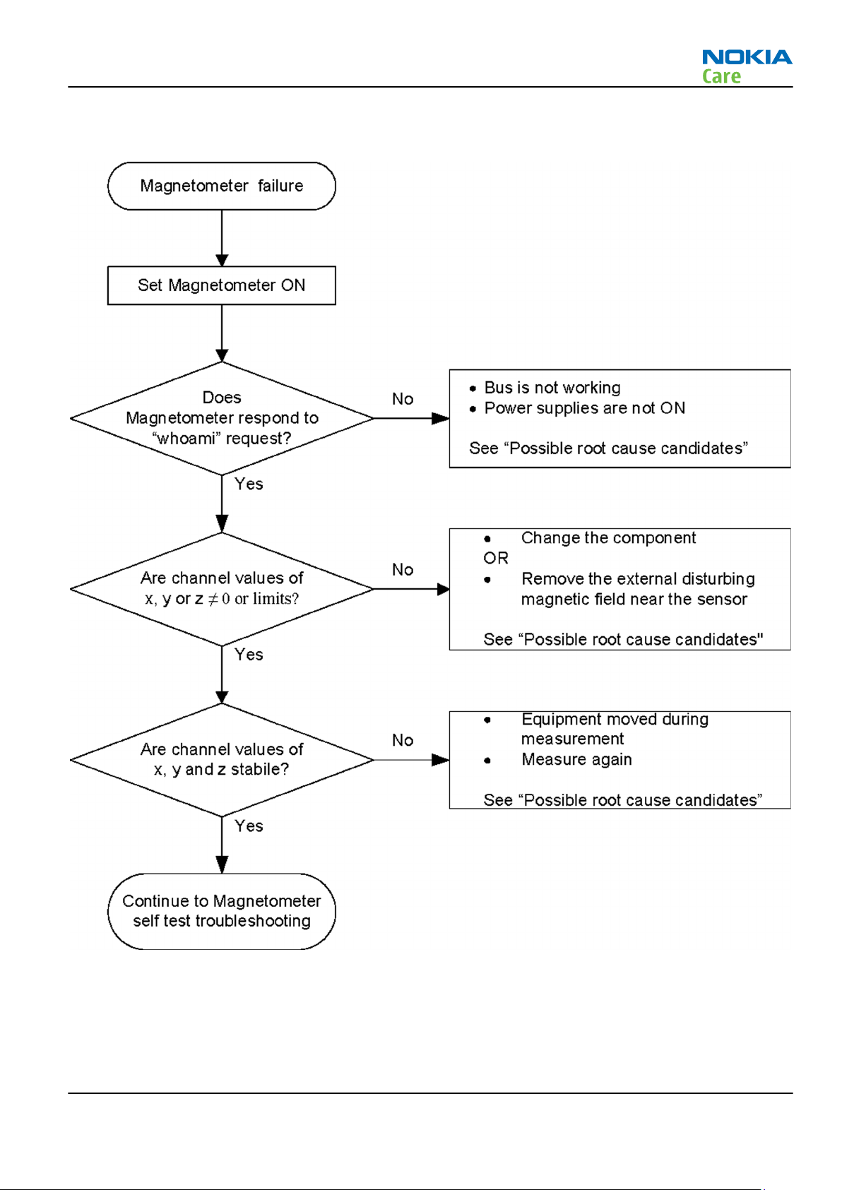
Magnetometer troubleshooting
Equipment
•
Non-magnetic, horizontal table
•
nearest ferromagnetic part, distance more than 50 cm
•
Traditional needle type compass for reference
•
Rotating platform (sheet of wood or plastic)
•
PC with Phoenix
Preparation of phone
•
Set the rotating platform to the table
•
Set the phone and reference compass to the rotating platform
•
Connect the phone to the PC and start Phoenix
Tests
•
General troubleshooting test
•
Self-test (ST)
•
Azimuth check test
Page 3 –30 COMPANY CONFIDENTIAL Issue 1
Copyright © 2009 Nokia. All rights reserved.
Page 77
RM-484; RM-485; RM-486
BB Troubleshooting
Magnetometer general troubleshooting
Issue 1 COMPANY CONFIDENTIAL Page 3 –31
Copyright © 2009 Nokia. All rights reserved.
Page 78

Magnetometer self test troubleshooting
RM-484; RM-485; RM-486
BB Troubleshooting
Page 3 –32 COMPANY CONFIDENTIAL Issue 1
Copyright © 2009 Nokia. All rights reserved.
Page 79

RM-484; RM-485; RM-486
BB Troubleshooting
Possible root cause candidates
•
Component sensor part is broken -> Change
•
Engine power supply level is not as specified -> Check Vdd
•
Too fast channel reads -> Try slower reading data rate
•
Motion during Self test session -> Stay and measure again
•
Saturating external magnetic field near the sensor
Azimuth check
•
Search magnetically quiet place for the test table
•
No disturbing elements near the table, such as motors, coils, electric currents or similar
•
Calibrate the phone as described in the user manual
•
The indicator must be GREEN
•
Rotate the platform manually one round on the horizontal table with steps of approximately 15° degrees
•
The reference angle direction value from the reference compass = REF(angle)
•
Read the phone value = ACT(angle)
•
Calculate for every step (24 steps)
•
Result(angle) = REF(angle) - ACT(angle)
•
The result is the real angle difference of angles in a 360° degrees continuous round
•
Criteria:
•
If the Result(angle) value < 15° degrees GO, otherwise NOGO
Display Troubleshooting
Display Troubleshooting
Display blank
There is no image on the display. Display looks the same as if the phone is off even when the phone is on.
Issue 1 COMPANY CONFIDENTIAL Page 3 –33
Copyright © 2009 Nokia. All rights reserved.
Page 80

RM-484; RM-485; RM-486
BB Troubleshooting
Image on display not correct
Image on the display can be corrupted or part of the image can be missing. If part of image is missing change
the UI module. If the image is otherwise corrupted, follow the path below.
Page 3 –34 COMPANY CONFIDENTIAL Issue 1
Copyright © 2009 Nokia. All rights reserved.
Page 81

RM-484; RM-485; RM-486
BB Troubleshooting
Illumination troubleshooting
Troubleshooting flow
S60 keyboard backlights are controlled by the Ambient Light Sensor. They are supposed to be illuminated
only in dark ambient light. At first, cover the ALS and check if they are OK. If they are not, go to the
troubleshooting diagram below.
Issue 1 COMPANY CONFIDENTIAL Page 3 –35
Copyright © 2009 Nokia. All rights reserved.
Page 82

RM-484; RM-485; RM-486
BB Troubleshooting
Troubleshooting flow
Page 3 –36 COMPANY CONFIDENTIAL Issue 1
Copyright © 2009 Nokia. All rights reserved.
Page 83

RM-484; RM-485; RM-486
BB Troubleshooting
Troubleshooting flow
ITU keyboard backlights are controlled by the Ambient Light Sensor. They are supposed to be illuminated
only in dark ambient light. At first, cover the ALS and check if they are OK. If they are not, go to the
troubleshooting diagram below.
Issue 1 COMPANY CONFIDENTIAL Page 3 –37
Copyright © 2009 Nokia. All rights reserved.
Page 84

LED driver troubleshooting
Troubleshooting flow
RM-484; RM-485; RM-486
BB Troubleshooting
Page 3 –38 COMPANY CONFIDENTIAL Issue 1
Copyright © 2009 Nokia. All rights reserved.
Page 85

RM-484; RM-485; RM-486
BB Troubleshooting
I/O expander troubleshooting
Troubleshooting flow
Audio Troubleshooting
Audio troubleshooting test instructions
Single-ended external earpiece and differential internal earpiece outputs can be measured either with a
single-ended or a differential probe.
When measuring with a single-ended probe each output is measured against the ground.
Internal handsfree output is measured using a current probe, if a special low-pass filter designed for
measuring a digital amplifier is not available. Note also that when using a current probe, the input signal
frequency must be set to 2 kHz.
The input signal for each loop test can be either single-ended or differential. Exception to this is a digital
microphone, which needs input signal from an external sound source (laptop speaker) to playback eg. 1kHz
sine wave from 5cm distance
Issue 1 COMPANY CONFIDENTIAL Page 3 –39
Copyright © 2009 Nokia. All rights reserved.
Page 86

RM-484; RM-485; RM-486
BB Troubleshooting
Required equipment
The following equipment is needed for the tests:
•
Oscilloscope
•
Function generator (sine waveform)
•
Current probe (Internal handsfree DPMA output measurement)
•
Phoenix service software
•
Battery voltage 3.7V
•
Sound source (laptop speaker or B&K type 4231 calibrator)
Test procedure
Audio can be tested using the Phoenix audio routings option. Three different audio loop paths can be
activated:
•
External microphone to Internal earpiece
•
External microphone to Internal handsfree speaker
•
Internal microphone to External earpiece
Each audio loop sets routing from the specified input to the specified output enabling a quick in-out test.
Loop path gains are fixed and they cannot be changed using Phoenix. Correct pins and signals for each test
are presented in the following table.
Phoenix audio loop tests and test results
The results presented in the table apply when no accessory is connected and battery voltage is set to 3.7V.
Earpiece, internal microphone and speaker are in place during measurement. Applying a headset accessory
during measurement causes a significant drop in measured quantities.
The gain values presented in the table apply for a differential output vs. single-ended/differential input.
Loop test Input
terminal
External
Mic to
External
Earpiece
External
Mic to
Internal
Earpiece
External
Mic to
Internal
handsfre
e
HS_MIC &
GND
HS_MIC &
GND
HS_MIC &
GND
Output
terminal
HS_EAR_L
& GND
HS_EAR_R
& GND
EarP & -10 1000 310 1.2 NA
GND
EarN &
GND
J2103 &
J2104
J2101 &
J2102
Path gain
[dB]
(fixed)
-8.6 1000 367 1.2 NA
-6 1000
Input
voltage
[mVp-p]
Outout
voltage
[mVp-p]
Output DC
level [V]
Output
current
[mA]
Page 3 –40 COMPANY CONFIDENTIAL Issue 1
Copyright © 2009 Nokia. All rights reserved.
Page 87

RM-484; RM-485; RM-486
BB Troubleshooting
Loop test Input
terminal
Digital
Mic to
External
Earpiece
Acoustica
l input,
1KHz sine
wave
Measurement data
Earpiece signal
Output
terminal
HS_EAR_L
& GND
Path gain
[dB]
(fixed)
Input
voltage
[mVp-p]
Outout
voltage
[mVp-p]
Output DC
level [V]
NA 94 dB SPL 100 NA
Output
current
[mA]
Figure 14 Single-ended output waveform of the Ext_in_HP_out measurement when earpiece is connected
Integrated handsfree signal
Figure 15 Single-ended output waveform of the Ext_in_IHF_out out loop measurement when speaker is connected
(measured at speaker pads), no filter is used
External output from AV
Issue 1 COMPANY CONFIDENTIAL Page 3 –41
Copyright © 2009 Nokia. All rights reserved.
Page 88

Figure 16 Single-ended output waveform of the Ext_in_Ext_out loop
External output from AV (acoustic input)
RM-484; RM-485; RM-486
BB Troubleshooting
Figure 17 Single-ended output waveform of the Digital_stereo_microphone_in_Ext_out loop
Page 3 –42 COMPANY CONFIDENTIAL Issue 1
Copyright © 2009 Nokia. All rights reserved.
Page 89
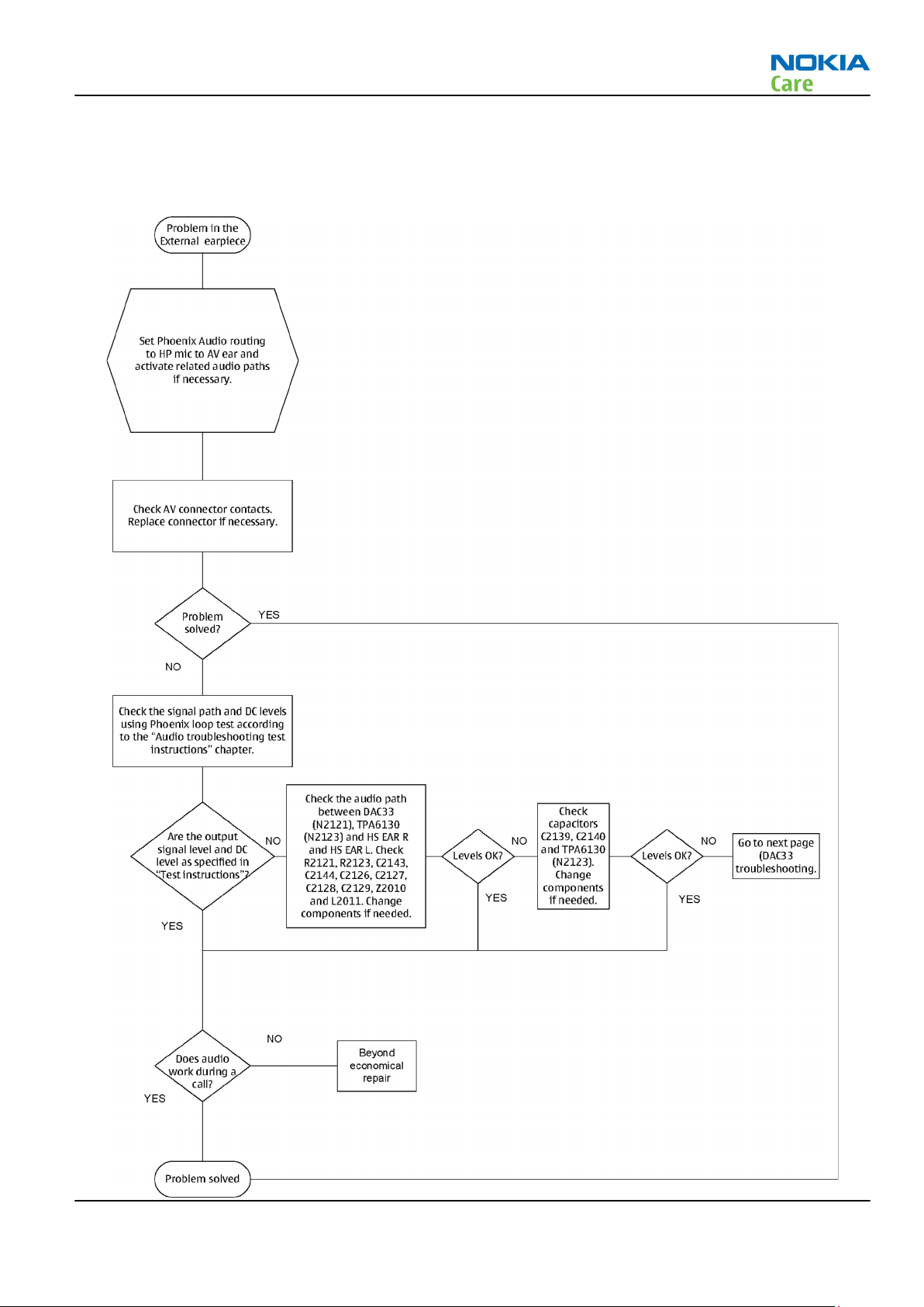
RM-484; RM-485; RM-486
BB Troubleshooting
External earpiece troubleshooting
Troubleshooting flow
Issue 1 COMPANY CONFIDENTIAL Page 3 –43
Copyright © 2009 Nokia. All rights reserved.
Page 90

DAC33 troubleshooting
Troubleshooting flow
RM-484; RM-485; RM-486
BB Troubleshooting
Page 3 –44 COMPANY CONFIDENTIAL Issue 1
Copyright © 2009 Nokia. All rights reserved.
Page 91

RM-484; RM-485; RM-486
BB Troubleshooting
External microphone troubleshooting
Troubleshooting flow
Issue 1 COMPANY CONFIDENTIAL Page 3 –45
Copyright © 2009 Nokia. All rights reserved.
Page 92

Internal earpiece troubleshooting
Troubleshooting flow
RM-484; RM-485; RM-486
BB Troubleshooting
Page 3 –46 COMPANY CONFIDENTIAL Issue 1
Copyright © 2009 Nokia. All rights reserved.
Page 93

RM-484; RM-485; RM-486
BB Troubleshooting
Internal handsfree speaker troubleshooting
Troubleshooting flow
Issue 1 COMPANY CONFIDENTIAL Page 3 –47
Copyright © 2009 Nokia. All rights reserved.
Page 94

Internal microphone troubleshooting
Troubleshooting flow
RM-484; RM-485; RM-486
BB Troubleshooting
Page 3 –48 COMPANY CONFIDENTIAL Issue 1
Copyright © 2009 Nokia. All rights reserved.
Page 95
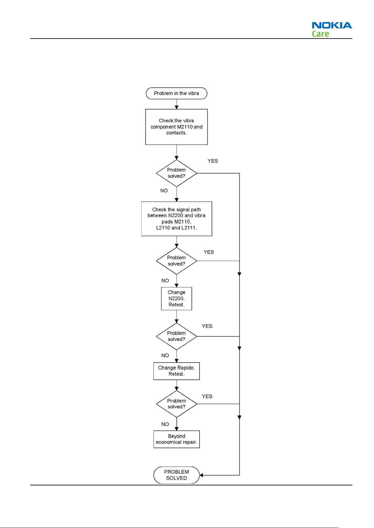
RM-484; RM-485; RM-486
BB Troubleshooting
Vibra troubleshooting
Troubleshooting flow
Issue 1 COMPANY CONFIDENTIAL Page 3 –49
Copyright © 2009 Nokia. All rights reserved.
Page 96

RM-484; RM-485; RM-486
BB Troubleshooting
ALS Technical Description and Troubleshooting
Ambient Light Sensor
Ambient Light Sensor
Figure 18 Ambient Light Sensor
Ambient Light Sensor consists of the following components:
•
Light guide
•
Ambient Light Sensor (ALS)
ALS is a digital I2C interface component, having two channels with different spectral sensitivities. When
combined, the component responds to illuminance similar as human eye.
•
Vdd Filtering capacitor C6504
Ambient Light Sensor information is used to control keypad and display brightness of the phone.
Keyboard backlight is turned OFF, when it’s not needed. Display brightness is dimmed, when environment
lighting is dark.
Ambient Light Sensor is calibrated in production and can be re-tuned in service points though not
recommended unless calibration coefficient are lost for some reason
ALS troubleshooting
Context
Functionality check:
Steps
1. Connect phone to Phoenix and set the phone (e.g. on the table) so that the amount of ambient light seen
by ALS is as stable as possible.
2. Start Phoenix
3. Choose File -> Scan product
4. Choose Testing -> Display Test
5. Open the Lights tab, check Ambient Light Sensor check box, click Read, cover the sensor and click Read
again. When covered, Luminance reading should be less than after clicking Read without covering the
sensor.
Page 3 –50 COMPANY CONFIDENTIAL Issue 1
Copyright © 2009 Nokia. All rights reserved.
Page 97

RM-484; RM-485; RM-486
BB Troubleshooting
6. If component doesn’t give any reading or reading doesn’t change when sensor is/is not covered, replace
the part.
Note: After replacing the ALS. If calibration values of the new sensor are lost or for some other
reason, ALS re-tuning is required (see instructions later in this document).
When doing the ALS calibration procedure, it is required to have a reference phone, which includes
calibrated ALS. ALS re-tuning instructions show why the reference phone is needed.
Re-tuning ALS
Steps
1. Connect reference phone to Phoenix and set the phone (e.g. on the table) so that the amount of ambient
light seen by ALS is as stable as possible.
2. Start Phoenix.
3. Choose File→Scan Product.
Issue 1 COMPANY CONFIDENTIAL Page 3 –51
Copyright © 2009 Nokia. All rights reserved.
Page 98
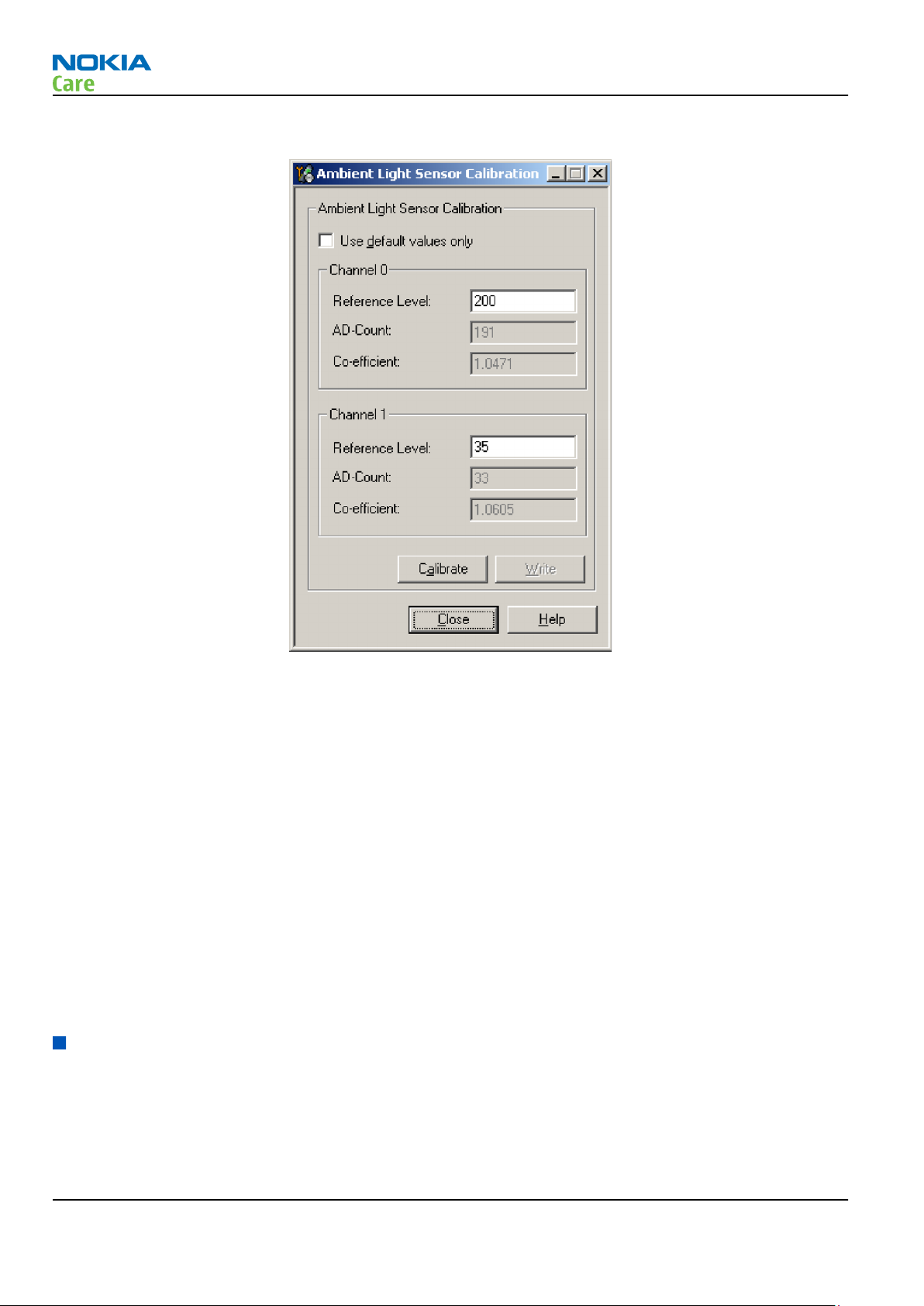
RM-484; RM-485; RM-486
BB Troubleshooting
4. Choose Tuning -> Ambient Light Sensor Calibration. You should see the following window:
5. Read AD-count values for Channel 0 and Channel 1 by click Read button and write them down.
6. Repeat 1-5 for the phone to be calibrated and make sure the phone to be calibrated is located in the
same place as reference phone was when luminance reading was taken.
7. Calculate co-efficient from reference phone and phone to be calibrated AD-count values by division: Coefficient = AD-count(reference phone) / AD-count(phone to be calibrated), write down the calculated coefficient values.
8. -> Iterate by changing Channel 0 and Channel 1 (reference level) values (remove cross from ‘Use default
values only’). After writing some value to Channel 0 and Channel 1 (reference value), calibrate button
must be pressed. Stop iterating when Co-efficient is equal to Co-efficient calculated in step 7. Note that
decimal numbers should be used in the iteration in order to achieve enough precision (e.g. 200.2455)
9. After having same Co-efficient value in “Co-efficient” textbox as the calculated value, make sure that
ambient light values (read using Testing → Display Test → “Luminance” textbox) are almost the same
in reference phone and calibrated phone. Remember that illuminance readings for reference and
calibrated phones must be done in the same ambient light conditions. If illuminance values differs a lot
(difference max. +- 10%), repeat whole ALS re-tuning procedure.
10. To end the calibration, click Close.
Bluetooth and FM Radio Troubleshooting
Introduction to Bluetooth/FM radio troubleshooting
Bluetooth/WLAN antenna
The BT RF signal is routed from BTFMRDS2.3M through the WLAN module to the shared WLAN/BT antenna in
the phone's C-cover.
Page 3 –52 COMPANY CONFIDENTIAL Issue 1
Copyright © 2009 Nokia. All rights reserved.
Page 99

RM-484; RM-485; RM-486
BB Troubleshooting
Figure 19 Bluetooth/WLAN antenna
Introduction to Bluetooth/FM radio troubleshooting
The Bluetooth and FM radio are combined in the same ASIC, so both features are checked when
troubleshooting.
The following problems can occur with the Bluetooth and FM radio hardware:
Symptom Problem Repair solution
Unable to switch on Bluetooth on
phone user interface
Able to send data file to another
Bluetooth device, but unable to
hear audio through functional
Bluetooth headset
Able to switch on Bluetooth on
phone user interface, but unable
to detect other Bluetooth devices
Able to turn on FM radio and
Bluetooth on phone user
interface, but unable to detect
local FM radio stations with Nokia
headset inserted
Open circuit solder joints or
component failure of BTH/FM
ASIC/module BB ASICs or SMD
components.
Open circuit solder joints or
component failure of BTH/FM
ASIC/module BB ASICs.
Open circuit solder joints or
Pogo Pins not making contact
with c-cover
Open circuit solder joints or
detached component in FM
antenna circuit
Replacement of Bluetooth/
FM ASIC/module
Replacement of Bluetooth/
FM ASIC/module
Repair or replace c-cover
Repair of FM antenna
connection or FM circuit
component
Issue 1 COMPANY CONFIDENTIAL Page 3 –53
Copyright © 2009 Nokia. All rights reserved.
Page 100
RM-484; RM-485; RM-486
BB Troubleshooting
Symptom Problem Repair solution
Able to perform scans to detect
local FM radio stations with
functional Nokia headset
inserted, but unable to hear FM
audio through headset
Users may experience the following problems resulting in functional phones being returned to the repair
centre:
Symptom Problem Repair solution
Bluetooth feature does not
operate as desired with another
Bluetooth device
Poor FM radio reception (unable
to detect many radio stations)
Open circuit solder joints or
detached component in FM
audio path between Bluetooth/
FM ASIC and headset
Bluetooth Profile implemented
in Bluetooth accessory not
supported in Nokia phone
Nokia headset not being used Use Nokia headset
Repair of FM audio circuit
Use Bluetooth accessory with
Bluetooth profiles supported
by phone
Test coverage
The tests listed in the table below should be performed to verify whether the Bluetooth and FM receiver and
transmitter are functional. The use of Self Tests are described in section
BT and FM Self Tests in Phoenix
Test Test Coverage Repair solution
Blueooth Self Test: ST_LPRF_IF_TEST Bluetooth-FM ASIC UART interface
(controls Bluetooth and FM
receiver and transmitter)
Bluetooth Self Test:
ST_BT_WAKEUP_TEST
Bluetooth Self Test:
ST_LPRF_AUDIO_LINES_TEST
Bluetooth Functional Test: BER test
with BT-Box or functional test with
other Bluetooth device
FM Radio Self Test: ST_RADIO_TEST FM Radio I2C interface Replacement of Bluetooth/FM
FM Radio Functional Test: Perform
scan for local radio stations and
check station list displayed on
phone
FM Radio Functional Test: Listen to
local radio station
Bluetooth ASIC interrupt control
interface
Bluetooth ASIC PCM interface Replacement of Bluetooth/FM
Bluetooth antenna circuit Repair of Bluetooth antenna
FM receiver antenna circuit Repair of FM antenna circuit
FM receiver audio circuit Repair of FM receiver audio
Replacement of Bluetooth/FM
ASIC (or repair of phone BB)
Replacement of Bluetooth/FM
ASIC (or repair of phone BB)
ASIC (or repair of phone BB)
circuit (including RF filter or
WLAN switch if fitted)
ASIC (or repair of phone BB)
(between BTHFM ASIC and
headset connector)
circuit (between BTHFM ASIC
and headset connector)
The self tests run from Phoenix software are used for fault diagnosis.
If Phoenix software is not available the functional tests with phone accessories are sufficient to verify the
functionality Bluetooth and FM radio receiver and transmitter.
Page 3 –54 COMPANY CONFIDENTIAL Issue 1
Copyright © 2009 Nokia. All rights reserved.
 Loading...