

Page 1

Nokia Customer Care
Service Manual
RM-179; RM-223 (Nokia N81)
Mobile Terminal
Part No: (Issue 1)
COMPANY CONFIDENTIAL
Copyright © 2007 Nokia. All rights reserved.
Page 2

Amendment Record Sheet
Amendment Record Sheet
Amendment No Date Inserted By Comments
Issue 1 09/2007 MHa
RM-179; RM-223
Page ii COMPANY CONFIDENTIAL Issue 1
Copyright © 2007 Nokia. All rights reserved.
Page 3

RM-179; RM-223
Copyright
Copyright
Copyright © 2007 Nokia. All rights reserved.
Reproduction, transfer, distribution or storage of part or all of the contents in this document in any form
without the prior written permission of Nokia is prohibited.
Nokia, Nokia Connecting People, and Nokia X and Y are trademarks or registered trademarks of Nokia
Corporation. Other product and company names mentioned herein may be trademarks or tradenames of
their respective owners.
Nokia operates a policy of continuous development. Nokia reserves the right to make changes and
improvements to any of the products described in this document without prior notice.
Under no circumstances shall Nokia be responsible for any loss of data or income or any special, incidental,
consequential or indirect damages howsoever caused.
The contents of this document are provided "as is". Except as required by applicable law, no warranties of
any kind, either express or implied, including, but not limited to, the implied warranties of merchantability
and fitness for a particular purpose, are made in relation to the accuracy, reliability or contents of this
document. Nokia reserves the right to revise this document or withdraw it at any time without prior notice.
The availability of particular products may vary by region.
IMPORTANT
This document is intended for use by qualified service personnel only.
Issue 1 COMPANY CONFIDENTIAL Page iii
Copyright © 2007 Nokia. All rights reserved.
Page 4

RM-179; RM-223
Warnings and cautions
Warnings and cautions
Warnings
• IF THE DEVICE CAN BE INSTALLED IN A VEHICLE, CARE MUST BE TAKEN ON INSTALLATION IN VEHICLES FITTED
WITH ELECTRONIC ENGINE MANAGEMENT SYSTEMS AND ANTI-SKID BRAKING SYSTEMS. UNDER CERTAIN FAULT
CONDITIONS, EMITTED RF ENERGY CAN AFFECT THEIR OPERATION. IF NECESSARY, CONSULT THE VEHICLE DEALER/
MANUFACTURER TO DETERMINE THE IMMUNITY OF VEHICLE ELECTRONIC SYSTEMS TO RF ENERGY.
• THE PRODUCT MUST NOT BE OPERATED IN AREAS LIKELY TO CONTAIN POTENTIALLY EXPLOSIVE ATMOSPHERES,
FOR EXAMPLE, PETROL STATIONS (SERVICE STATIONS), BLASTING AREAS ETC.
• OPERATION OF ANY RADIO TRANSMITTING EQUIPMENT, INCLUDING CELLULAR TELEPHONES, MAY INTERFERE
WITH THE FUNCTIONALITY OF INADEQUATELY PROTECTED MEDICAL DEVICES. CONSULT A PHYSICIAN OR THE
MANUFACTURER OF THE MEDICAL DEVICE IF YOU HAVE ANY QUESTIONS. OTHER ELECTRONIC EQUIPMENT MAY
ALSO BE SUBJECT TO INTERFERENCE.
• BEFORE MAKING ANY TEST CONNECTIONS, MAKE SURE YOU HAVE SWITCHED OFF ALL EQUIPMENT.
Cautions
• Servicing and alignment must be undertaken by qualified personnel only.
• Ensure all work is carried out at an anti-static workstation and that an anti-static wrist strap is worn.
• Ensure solder, wire, or foreign matter does not enter the telephone as damage may result.
• Use only approved components as specified in the parts list.
• Ensure all components, modules, screws and insulators are correctly re-fitted after servicing and
alignment.
• Ensure all cables and wires are repositioned correctly.
• Never test a mobile phone WCDMA transmitter with full Tx power, if there is no possibility to perform the
measurements in a good performance RF-shielded room. Even low power WCDMA transmitters may disturb
nearby WCDMA networks and cause problems to 3G cellular phone communication in a wide area.
• During testing never activate the GSM or WCDMA transmitter without a proper antenna load, otherwise
GSM or WCDMA PA may be damaged.
Page iv COMPANY CONFIDENTIAL Issue 1
Copyright © 2007 Nokia. All rights reserved.
Page 5

RM-179; RM-223
ESD protection
ESD protection
Nokia requires that service points have sufficient ESD protection (against static electricity) when servicing
the phone.
Any product of which the covers are removed must be handled with ESD protection. The SIM card can be
replaced without ESD protection if the product is otherwise ready for use.
To replace the covers ESD protection must be applied.
All electronic parts of the product are susceptible to ESD. Resistors, too, can be damaged by static electricity
discharge.
All ESD sensitive parts must be packed in metallized protective bags during shipping and handling outside
any ESD Protected Area (EPA).
Every repair action involving opening the product or handling the product components must be done under
ESD protection.
ESD protected spare part packages MUST NOT be opened/closed out of an ESD Protected Area.
For more information and local requirements about ESD protection and ESD Protected Area, contact your local
Nokia After Market Services representative.
Issue 1 COMPANY CONFIDENTIAL Page v
Copyright © 2007 Nokia. All rights reserved.
Page 6

RM-179; RM-223
Care and maintenance
Care and maintenance
This product is of superior design and craftsmanship and should be treated with care. The suggestions below
will help you to fulfil any warranty obligations and to enjoy this product for many years.
• Keep the phone and all its parts and accessories out of the reach of small children.
• Keep the phone dry. Precipitation, humidity and all types of liquids or moisture can contain minerals that
will corrode electronic circuits.
• Do not use or store the phone in dusty, dirty areas. Its moving parts can be damaged.
• Do not store the phone in hot areas. High temperatures can shorten the life of electronic devices, damage
batteries, and warp or melt certain plastics.
• Do not store the phone in cold areas. When it warms up (to its normal temperature), moisture can form
inside, which may damage electronic circuit boards.
• Do not drop, knock or shake the phone. Rough handling can break internal circuit boards.
• Do not use harsh chemicals, cleaning solvents, or strong detergents to clean the phone.
• Do not paint the phone. Paint can clog the moving parts and prevent proper operation.
• Use only the supplied or an approved replacement antenna. Unauthorised antennas, modifications or
attachments could damage the phone and may violate regulations governing radio devices.
All of the above suggestions apply equally to the product, battery, charger or any accessory.
Page vi COMPANY CONFIDENTIAL Issue 1
Copyright © 2007 Nokia. All rights reserved.
Page 7

RM-179; RM-223
Company Policy
Company Policy
Our policy is of continuous development; details of all technical modifications will be included with service
bulletins.
While every endeavour has been made to ensure the accuracy of this document, some errors may exist. If
any errors are found by the reader, NOKIA MOBILE PHONES Business Group should be notified in writing/email.
Please state:
• Title of the Document + Issue Number/Date of publication
• Latest Amendment Number (if applicable)
• Page(s) and/or Figure(s) in error
Please send to:
NOKIA CORPORATION
Nokia Mobile Phones Business Group
Nokia Customer Care
PO Box 86
FIN-24101 SALO
Finland
E-mail: Service.Manuals@nokia.com
Issue 1 COMPANY CONFIDENTIAL Page vii
Copyright © 2007 Nokia. All rights reserved.
Page 8

RM-179; RM-223
Battery information
Battery information
Note: A new battery's full performance is achieved only after two or three complete charge and
discharge cycles!
The battery can be charged and discharged hundreds of times but it will eventually wear out. When the
operating time (talk-time and standby time) is noticeably shorter than normal, it is time to buy a new battery.
Use only batteries approved by the phone manufacturer and recharge the battery only with the chargers
approved by the manufacturer. Unplug the charger when not in use. Do not leave the battery connected to
a charger for longer than a week, since overcharging may shorten its lifetime. If left unused a fully charged
battery will discharge itself over time.
Temperature extremes can affect the ability of your battery to charge.
For good operation times with Li-Ion batteries, discharge the battery from time to time by leaving the product
switched on until it turns itself off (or by using the battery discharge facility of any approved accessory
available for the product). Do not attempt to discharge the battery by any other means.
Use the battery only for its intended purpose.
Never use any charger or battery which is damaged.
Do not short-circuit the battery. Accidental short-circuiting can occur when a metallic object (coin, clip or
pen) causes direct connection of the + and - terminals of the battery (metal strips on the battery) for example
when you carry a spare battery in your pocket or purse. Short-circuiting the terminals may damage the battery
or the connecting object.
Leaving the battery in hot or cold places, such as in a closed car in summer or winter conditions, will reduce
the capacity and lifetime of the battery. Always try to keep the battery between 15°C and 25°C (59°F and 77°
F). A phone with a hot or cold battery may temporarily not work, even when the battery is fully charged.
Batteries' performance is particularly limited in temperatures well below freezing.
Do not dispose of batteries in a fire!
Dispose of batteries according to local regulations (e.g. recycling). Do not dispose as household waste.
Page viii COMPANY CONFIDENTIAL Issue 1
Copyright © 2007 Nokia. All rights reserved.
Page 9

RM-179; RM-223
Nokia N81 Service Manual Structure
Nokia N81 Service Manual Structure
1 General Information
2 Service Tools and Service Concepts
3 Baseband Troubleshooting
4 RF troubleshooting
5 Camera Module Troubleshooting
6 System Module and User Interface
Glossary
Issue 1 COMPANY CONFIDENTIAL Page ix
Copyright © 2007 Nokia. All rights reserved.
Page 10

RM-179; RM-223
Nokia N81 Service Manual Structure
(This page left intentionally blank.)
Page x COMPANY CONFIDENTIAL Issue 1
Copyright © 2007 Nokia. All rights reserved.
Page 11

Nokia Customer Care
1 — General Information
Issue 1 COMPANY CONFIDENTIAL Page 1 –1
Copyright © 2007 Nokia. All rights reserved.
Page 12

RM-179; RM-223
General Information
(This page left intentionally blank.)
Page 1 –2 COMPANY CONFIDENTIAL Issue 1
Copyright © 2007 Nokia. All rights reserved.
Page 13

RM-179; RM-223
General Information
Table of Contents
Product selection....................................................................................................................................................1–5
Product features and sales package.....................................................................................................................1–5
Mobile enhancements............................................................................................................................................1–7
Technical specifications.........................................................................................................................................1–9
Transceiver general specifications ..................................................................................................................1–9
Main RF characteristics for GSM850/EGSM900/GSM1800/GSM1900 and WCDMA phones ...........................1–9
Battery endurance.......................................................................................................................................... 1–10
List of Figures
Figure 1 RM-179 phone..........................................................................................................................................1–5
Figure 2 RM-223 phone..........................................................................................................................................1–5
Issue 1 COMPANY CONFIDENTIAL Page 1 –3
Copyright © 2007 Nokia. All rights reserved.
Page 14

RM-179; RM-223
General Information
(This page left intentionally blank.)
Page 1 –4 COMPANY CONFIDENTIAL Issue 1
Copyright © 2007 Nokia. All rights reserved.
Page 15

RM-179; RM-223
General Information
Product selection
RM-179/223 is a WCDMA/GSM dual mode handportable phone. It supports EGSM900/1800/1900 and
WCDMA2100. RM-179 has 8GB internal memory and RM-223 a micro SD card.
RM-179/223 is a 3GPP Release 4 terminal supporting CSD/HCSD, GPRS/EGPRS and WCDMA data bearers. For
WCDMA the maximum bit rate is up to 384 kbps for downlink and 384 kbps for uplink with simultaneous CS
speech or CS video (max. 64 kbps).
For 2G and 2.5G networks the RM-179/223 is a Class B EGPRS MSC 32, which means a in maximum download
speed of up to 296kbit/s with EGPRS, and up to 107kbit/s with GPRS. According to GSM standard 05.05 it
responds to class 4 (max. 2W) in GSM 850 and EGSM 900, class 1 (1W) is DCS 1800, and class 1 in PCS 1900.
RM-179/223 supports Bluetooth 2.0 + EDR standard and two-way video calls with two integrated cameras,
on the front and one on the back. The main camera is an integrated 2 Megapixel camera with a digital zoom
and the secondary CIF camera is for video calls.
RM-179/223 is an MMS (Multimedia Messaging Service) enabled multimedia device. The MMS implementation
follows the OMA MMS standard release 1.2. It has a large 2.4’’ QVGA (320x240 pixels) TFT display with 16
million colors.
The HTML browser is a highly advanced internet browser also capable of viewing operator domain XHTML
Mobile Profile (MP) content.
RM-179/223 uses Symbian 9.x (S60) operating system and supports also MIDP Java 2.0, providing a good
platform for compelling 3rd party applications.
Figure 1 RM-179 phone Figure 2 RM-223 phone
Product features and sales package
Hardware features
• GPRS multi slot at least class 10 (4+1, 2+2), class B
Issue 1 COMPANY CONFIDENTIAL Page 1 –5
Copyright © 2007 Nokia. All rights reserved.
Page 16

RM-179; RM-223
General Information
• EGPRS multi slot at least class 10 (4+1, 2+2), class B
• DTM Support (MSC11)
• Speech codecs: FR, EFR, AMR
• Internal handsfree/music stereo speaker
• Internal vibrating alert
• 2mm charger
Display and keys
• Active matrix 2.4” QVGA main colour display (320 x 240 pixels), up to 16 million colors
• Media keys: play/pause, forward, rewind, stop
• Keys: two gaming keys, two softkeys, send & end, 5-way navigator, S60 keys (application, clear), ITU-T
keypad, volume keys (up & down), camera key, power key, lock switch, Navi™ wheel
Connectivity
• WLAN IEEE802.11 b/g with UPnP support
• Bluetooth Specification 2.0 (profiles supported: DUN, OPP, FTP, HFP, GOEP, GAP, SPP, HSP, BIP, A2DP)
• Micro USB 2.0 Full Speed (mass storage class)
• Nokia AV Connector 3.5mm
Software features
• Operating system: Symbian ver. 9.2
• User interface: S60 3rd Edition, Feature Pack (S60 3.1)
• NCP 5.0
• Java™ MIDP 2.0, CLDC 1.1
• Flash Lite 2.0
• C++ and Java SDKs
Additional technical specifications
• Protocols: MTP, UPnP, TCP/IP
Memory
• Internal flash memory (8 GB) (RM-179)
• MicroSD card (support up to 32GB, hotswap) (RM-223)
Sales package
• Transceiver RM-179/223
• 3.5mm Stereo Headset with Remote Control (HS-45 + AD-54)
• MicroSD card (1GB) (MU-22) (only RM-223)
• Micro USB Data Cable (CA-101)
• Battery (BP-6MT)
• Travel Charger (AC-5)
• CD ROM
• User Guide
• Quick Guide
Page 1 –6 COMPANY CONFIDENTIAL Issue 1
Copyright © 2007 Nokia. All rights reserved.
Page 17

RM-179; RM-223
General Information
• Sales carton
Mobile enhancements
Data
Enhancement Type
Charging connectivity cable CA-100
Micro-USB connect cable CA-101
MicroSD card MU-27 (256 MB)
MU-28 (512 MB)
MU-22 (1 GB)
MU-37 (2 GB)
MU-41 (4 GB)
Power
Enhancement Type
Battery 1050 mAh BP-6MT
Travel charger AC-4
AC-5
Mobile charger DC-4
Baby feeder, large battery to charge phone battery
3 -5 times
First aid charger DC-8
Retractable mobile charger DC-9
Charger adapter CA-44
DC-1
Audio
Enhancement Type
Stereo headset HS-43
HS-48
Music headset HS-16
AD-43
Headset HS-41
3.5 mm headphone HS-44
HS-45
HS-61
HS-62
Issue 1 COMPANY CONFIDENTIAL Page 1 –7
Copyright © 2007 Nokia. All rights reserved.
Page 18

Enhancement Type
Bluetooth headset BH-200
BH-300
BH-600
BH-301
BH-302
BH-801
BH-202
BH-700
BH-800
BH-900
HS-26W
BH-201
RM-179; RM-223
General Information
BH-207
BH-701
BH-902
BH-100
BH-303
BH-208
BH-602
Bluetooth stereo headset HS-12W
BH-601
BH-500
BH-501
TTY adapter HDA-12
Messaging
Enhancement Type
Wireless keyboard SU-8W
Digital pen SU-27W
Music
Enhancement Type
Music headphones HS-61
Advanced music headphones HS-62
Mini speaker MD-4
Page 1 –8 COMPANY CONFIDENTIAL Issue 1
Copyright © 2007 Nokia. All rights reserved.
Page 19

RM-179; RM-223
General Information
Enhancement Type
Music speaker MD-3
Bluetooth speaker MD-5W
Positioning
Enhancement Type
Wireless GPS module LD-3W
Car
Enhancement Type
Wireless plug-in car handsfree HF-6W
HF-33W
HF-34W
HF-35W
Advanced car kit CK-7W
CK-15W
CK-20W
CK-25W
Car kit Nokia 616
Universal holder CR-82
Technical specifications
Transceiver general specifications
Unit Dimensions (L x W x T) (mm) Weight (g)
Transceiver with BP-6MT
1050 mAh li-ion battery
102 x 50 x 17.9 ~140 88
Volume (cm3)
Main RF characteristics for GSM850/EGSM900/GSM1800/GSM1900 and WCDMA phones
Parameter Unit
Cellular system GSM850, EGSM900, GSM1800/1900, or WCDMA2100
Rx frequency band GSM850: 869 - 894MHz
EGSM900: 925 - 960 MHz
GSM1800: 1805 - 1880 MHz
GSM1900: 1930 - 1990 MHz
WCDMA2100: 2110 - 2170 MHz
Issue 1 COMPANY CONFIDENTIAL Page 1 –9
Copyright © 2007 Nokia. All rights reserved.
Page 20

General Information
Parameter Unit
Tx frequency band GSM850: 824 - 849MHz
EGSM900: 880 - 915 MHz
GSM1800: 1710 - 1785 MHz
GSM1900: 1850 - 1910 MHz
WCDMA2100: 1920 - 1980 MHz
Output power GSM850: +5 ...+33dBm/3.2mW ... 2W
GSM900: +5 … +33dBm/3.2mW … 2W
GSM1800: +0 … +30dBm/1.0mW … 1W
GSM1900: +0 … +30dBm/1.0mW … 1W
WCDMA -50 … 24 dBm
Number of RF channels GSM850: 125
GSM900: 175
RM-179; RM-223
GSM1800: 375
GSM1900: 299
Channel spacing 200 kHz
Number of Tx power levels GSM850: 15
GSM900: 15
GSM1800: 16
GSM1900: 16
Battery endurance
Battery Talk time Stand-by Video call
BP-6MT 1050 mAh 4.3h (GSM@29dBm)
3h (WCDMA@10dBm)
Note: Operation times may vary depending on radio access technology used, operator network
configuration and usage.
17days (GSM)
20days (WCDMA)
Music playback
time
2.1h 10h
time
Charging times
AC-5
1h20min
Page 1 –10 COMPANY CONFIDENTIAL Issue 1
Copyright © 2007 Nokia. All rights reserved.
Page 21

Nokia Customer Care
2 — Service Tools and Service
Concepts
Issue 1 COMPANY CONFIDENTIAL Page 2 –1
Copyright © 2007 Nokia. All rights reserved.
Page 22

RM-179; RM-223
Service Tools and Service Concepts
(This page left intentionally blank.)
Page 2 –2 COMPANY CONFIDENTIAL Issue 1
Copyright © 2007 Nokia. All rights reserved.
Page 23

RM-179; RM-223
Service Tools and Service Concepts
Table of Contents
Service tools............................................................................................................................................................2–5
Product specific tools........................................................................................................................................2–5
FS-37..............................................................................................................................................................2–5
MJ-114 ...........................................................................................................................................................2–6
RJ-130 ............................................................................................................................................................2–6
SA-113 ...........................................................................................................................................................2–7
SA-113 attenuation values ...............................................................................................................................2–7
General tools......................................................................................................................................................2–8
CU-4................................................................................................................................................................2–9
FLS-5 ........................................................................................................................................................... 2–10
FPS-10......................................................................................................................................................... 2–10
JXS-1............................................................................................................................................................ 2–10
PK-1............................................................................................................................................................. 2–11
PKD-1 .......................................................................................................................................................... 2–11
RJ-104 ......................................................................................................................................................... 2–11
RJ-157 ......................................................................................................................................................... 2–11
RJ-160 ......................................................................................................................................................... 2–12
RJ-169 ......................................................................................................................................................... 2–12
RJ-93 ........................................................................................................................................................... 2–12
SB-6............................................................................................................................................................. 2–12
SPS-1........................................................................................................................................................... 2–13
SRT-6........................................................................................................................................................... 2–13
SS-46........................................................................................................................................................... 2–13
SS-62........................................................................................................................................................... 2–13
ST-37........................................................................................................................................................... 2–14
ST-40........................................................................................................................................................... 2–14
ST-55........................................................................................................................................................... 2–14
ST-59........................................................................................................................................................... 2–14
SX-4............................................................................................................................................................. 2–14
Cables............................................................................................................................................................... 2–14
CA-101 ........................................................................................................................................................ 2–15
CA-35S......................................................................................................................................................... 2–15
CA-58RS....................................................................................................................................................... 2–15
DAU-9S........................................................................................................................................................ 2–16
PCS-1........................................................................................................................................................... 2–16
XCS-4........................................................................................................................................................... 2–16
XRF-1........................................................................................................................................................... 2–16
Service concepts .................................................................................................................................................. 2–17
POS (Point of Sale) flash concept .................................................................................................................. 2–17
Flash concept with FPS-10............................................................................................................................. 2–18
Flash concept with FLS-5 and SS-46 ............................................................................................................. 2–19
CU-4 flash concept with FPS-10..................................................................................................................... 2–20
Flash concept with FLS-5 and SS-62 ............................................................................................................. 2–21
Flash concept with FLS-5 and module jig .................................................................................................... 2–22
Module jig service concept............................................................................................................................ 2–23
Service concept for RF testing and RF/BB tuning........................................................................................ 2–24
RF testing / BB tuning concept...................................................................................................................... 2–25
RF/BB tuning and flashing with FPS-10 ....................................................................................................... 2–26
RF/BB tuning and flashing with FLS-5.......................................................................................................... 2–27
Bluetooth test concept with SB-6................................................................................................................. 2–28
Issue 1 COMPANY CONFIDENTIAL Page 2 –3
Copyright © 2007 Nokia. All rights reserved.
Page 24

RM-179; RM-223
Service Tools and Service Concepts
List of Tables
Table 1 MJ-114 attenuation table.........................................................................................................................2–6
List of Figures
Figure 3 POS flash concept ................................................................................................................................. 2–17
Figure 4 Basic flash concept with FPS-10.......................................................................................................... 2–18
Figure 5 Flash concept with FLS-5 and SS-46 ................................................................................................... 2–19
Figure 6 CU-4 flash concept with FPS-10........................................................................................................... 2–20
Figure 7 Basic flash concept with FLS-5 and SS-62 .......................................................................................... 2–21
Figure 8 Flash concept with FLS-5 and module jig .......................................................................................... 2–22
Figure 9 Module jig service concept .................................................................................................................. 2–23
Figure 10 Service concept for RF testing and RF/BB tuning............................................................................ 2–24
Figure 11 RF testing / BB tuning concept ......................................................................................................... 2–25
Figure 12 RF/BB tuning and flashing with FPS-10 ........................................................................................... 2–26
Figure 13 RF/BB tuning and flashing with FLS-5.............................................................................................. 2–27
Figure 14 Bluetooth test concept with SB-6..................................................................................................... 2–28
Page 2 –4 COMPANY CONFIDENTIAL Issue 1
Copyright © 2007 Nokia. All rights reserved.
Page 25

RM-179; RM-223
Service Tools and Service Concepts
Service tools
Product specific tools
The table below gives a short overview of service tools that can be used for testing, error analysis and repair
of product RM-179; RM-223, refer to various concepts.
FS-37 Flash adapter FS-37 is a product specific adapter for SW update and testing purposes.
It is compatible to SS-62 and SS-46. It provides galvanic connetion to
terminal test pads and battery connector.
Issue 1 COMPANY CONFIDENTIAL Page 2 –5
Copyright © 2007 Nokia. All rights reserved.
Page 26

RM-179; RM-223
Service Tools and Service Concepts
MJ-114 Module jig The module jig offers engine module component level repair, analysis
and alignment capabilities in combination with CU-4.
Features:
• connection interfaces for GSM, WCDMA, Bluetooth and WLAN
antenna
• galvanic connection to engine module test pads
• multiplexing between USB an FBUS media, controlled by VUSB with
CU-4
• lid interconnection with test points for measurements
• connection to lid assembly incl. displays and earpiece
• connector for e.g. CU-4 control unit
• connection for BT / SIM / SD-card module
Note: There is one RF connection for GSM and WCDMA 2100
Tx (transmitter path) and one RF connection for WCDMA 2100
Rx (receiver path).
•
Band (mid.
ch.)
Table 1 MJ-114 attenuation table
Channel Frequency
Attenuation
/MHz
Loss / dB
850 TX 189 836,6 0,32
850 RX 189 881,6 0,3
900 TX 37 897,4 0,27
900 RX 37 942,4 0,32
1800 TX 700 1747,8 0,33
1800 RX 700 1842,8 0,4
1900 TX 661 1880 0,35
1900 RX 661 1910 0,4
WCDMA TX 9750 1950 0,4
WCDMA RX 10700 2140 0,4
RJ-130 Soldering jig RJ-130 is a jig to support component level exchange with soldering
machines for the engine module.
Page 2 –6 COMPANY CONFIDENTIAL Issue 1
Copyright © 2007 Nokia. All rights reserved.
Page 27

RM-179; RM-223
Service Tools and Service Concepts
SA-113 RF coupler SA-113 is an RF coupler for WCDMA and GSM RF testing. It is used
together with the product-specific flash adapter.
For the attenuation values, see SA-113 attenuation values
(page 2–7).
SA-113 attenuation values
The following table shows attenuations from the antenna pads of the mobile terminal to the SMA connectors
of SA-113:
Band Channel
UP/
DOWN
Low 128 824.2 869.2 7.34 13.16 6.84 13.33
GSM 850
GSM 900
GSM 1800
GSM 1900
Mid 189 836.4 881.4 6.47 12.07 5.90 12.04
High 251 858.8 893.8 5.94 10.65 5.26 10.05
Low 975 880.2 925.2 11.76 6.45 10.52 5.44
Mid 37 897.4 942.8 10.56 6.12 8.63 4.79
High 124 915.8 960.8 4.31 6.48 4.13 4.93
Low 512 1710.2 1805.2 11.82 19.03 10.61 18.03
Mid 698 1747.4 1842.4 11.68 16.89 10.79 15.33
High 885 1784.8 1879.8 12.24 14.88 11.19 13.16
Low 512 1850.2 1930.2 12.15 12.06 11.05 11.32
Mid 661 1880.0 1960.0 11.85 12.79 10.95 11.76
High 810 1909.8 1989.8 11.93 13.20 11.35 11.89
9613 /
Low
10563 1922.4 2112.4 17.60 16.82 17.47 15.21
Slider OPEN Slider CLOSE
TX f [MHz] RX f [MHz] TX Loss
[dB]
RX Loss
[dB]
TX Loss
[dB]
RX Loss
[dB]
WCDMA I
Issue 1 COMPANY CONFIDENTIAL Page 2 –7
Mid
High
9750 /
10700 1950.0 2140.0 17.80 15.61 17.24 14.54
9887 /
10837 1977.6 2167.6 17.82 15.77 17.19 15.20
Copyright © 2007 Nokia. All rights reserved.
Page 28

RM-179; RM-223
Service Tools and Service Concepts
General tools
The table below gives a short overview of service tools that can be used for testing, error analysis and repair
of product RM-179; RM-223, refer to various concepts.
Page 2 –8 COMPANY CONFIDENTIAL Issue 1
Copyright © 2007 Nokia. All rights reserved.
Page 29

RM-179; RM-223
Service Tools and Service Concepts
CU-4 Control unit CU-4 is a general service tool used with a module jig and/or a flash
adapter. It requires an external 12 V power supply.
The unit has the following features:
• software controlled via USB
• EM calibration function
• Forwards FBUS/Flashbus traffic to/from terminal
• Forwards USB traffic to/from terminal
• software controlled BSI values
• regulated VBATT voltage
• 2 x USB2.0 connector (Hub)
• FBUS and USB connections supported
When using CU-4, note the special order of connecting cables and
other service equipment:
Instructions
1 Connect a service tool (jig, flash adapter) to CU-4.
2 Connect CU-4 to your PC with a USB cable.
3 Connect supply voltage (12 V)
4 Connect an FBUS cable (if necessary).
5 Start Phoenix service software.
Note: Phoenix enables CU-4 regulators via USB when it is
started.
Reconnecting the power supply requires a Phoenix restart.
Issue 1 COMPANY CONFIDENTIAL Page 2 –9
Copyright © 2007 Nokia. All rights reserved.
Page 30

RM-179; RM-223
Service Tools and Service Concepts
FLS-5 Flash device FLS-5 is a dongle and flash device incorporated into one package,
developed specifically for POS use.
Note: FLS-5 can be used as an alternative to PKD-1.
FPS-10 Flash prommer FPS-10 interfaces with:
• PC
• Control unit
• Flash adapter
• Smart card
FPS-10 flash prommer features:
• Flash functionality for BB5 and DCT-4 terminals
• Smart Card reader for SX-2 or SX-4
• USB traffic forwarding
• USB to FBUS/Flashbus conversion
• LAN to FBUS/Flashbus and USB conversion
• Vusb output switchable by PC command
FPS-10 sales package includes:
• FPS-10 prommer
• Power Supply with 5 country specific cords
• USB cable
Note: FPS-21 is substitute FPS-10 if FPS-10 has not been set
up.
JXS-1 RF shield box Because the WCDMA network disturbs the RX side testing of the WCDMA
phone and the Tx signal of the WCDMA phone can severely disturb the
WCDMA network, a shield box is needed in all testing, tuning and fault
finding which requires WCDMA RF signal.
The shield box is not an active device, it contains only passive filtering
components for RF attenuation.
Page 2 –10 COMPANY CONFIDENTIAL Issue 1
Copyright © 2007 Nokia. All rights reserved.
Page 31

RM-179; RM-223
Service Tools and Service Concepts
PK-1 Software protection
key
PK-1 is a hardware protection key with a USB interface. It has the same
functionality as the PKD-1 series dongle.
PK-1 is meant for use with a PC that does not have a series interface.
To use this USB dongle for security service functions please register
the dongle in the same way as the PKD-1 series dongle.
PKD-1 SW security device
SW security device is a piece of hardware enabling the use of the
service software when connected to the parallel (LPT) port of the PC.
Without the device, it is not possible to use the service software.
Printer or any such device can be connected to the PC through the
device if needed.
RJ-104 Rework jig RJ-104 is a rework jig used when servicing the BTHFM (D6000) module.
It is used together with rework stencil ST-37.
RJ-157 Rework jig RJ-157 is a jig used for soldering and as a rework jig for the engine
module. It is used together with the ST-55 stencil.
Issue 1 COMPANY CONFIDENTIAL Page 2 –11
Copyright © 2007 Nokia. All rights reserved.
Page 32

RM-179; RM-223
Service Tools and Service Concepts
RJ-160 Rework jig RJ-160 is a jig used for soldering and as a rework jig for the engine
module. It is used together with the ST-55 stencil.
RJ-169 Rework jig RJ-169 is a jig used for soldering and as a rework jig for the engine
module. It is used together with the ST-59 stencil.
RJ-93 Rework jig RJ-93 is used as a rework jig for the Front End Module (FEM).
This rework jig takes the FEM or power amplifier (PA) module (N7520)
for spreading the soldering paste to the component. Must be used
together with the ST-40 stencil.
SB-6 Bluetooth test and
interface box (sales
package)
The SB-6 test box is a generic service device used to perform Bluetooth
bit error rate (BER) testing, and establishing cordless FBUS connection
via Bluetooth. An ACP-8x charger is needed for BER testing and an
AXS-4 cable in case of cordless interface usage testing .
Sales package includes:
• SB-6 test box
• Installation and warranty information
Page 2 –12 COMPANY CONFIDENTIAL Issue 1
Copyright © 2007 Nokia. All rights reserved.
Page 33

RM-179; RM-223
Service Tools and Service Concepts
SPS-1 Soldering Paste
Spreader
The SPS-1 allows spreading of solder to the LGA components pads over
the rework stencils.
SRT-6 Opening tool SRT-6 is used to open phone covers.
SS-46 Interface adapter SS-46 acts as an interface adapter between the flash adapter and
FPS-10.
SS-62 Generic flash adapter
base for BB5
• generic base for flash adapters and couplers
• SS-62 equipped with a clip interlock system
• provides standardised interface towards Control Unit
• provides RF connection using galvanic connector or coupler
• multiplexing between USB and FBUS media, controlled by VUSB
Issue 1 COMPANY CONFIDENTIAL Page 2 –13
Copyright © 2007 Nokia. All rights reserved.
Page 34

RM-179; RM-223
Service Tools and Service Concepts
ST-37 BTHFM rework stencil ST-37 stencil is used with the RJ-104 rework jig to service the BTHFM
(D6000) module.
ST-40 Rework stencil ST-40 is a rework stencil that is used with the RJ-93 rework jig to
service the Front End Module (N7520).
ST-55 Rework stencil ST-55 is a rework stencil used with rework jig RJ-157 and RJ-160.
ST-59 Rework stencil ST-59 is a rework stencil used with rework jig RJ-169.
SX-4 Smart card SX-4 is a BB5 security device used to protect critical features in tuning
and testing.
SX-4 is also needed together with FPS-10 when DCT-4 phones are
flashed.
Cables
The table below gives a short overview of service tools that can be used for testing, error analysis and repair
of product RM-179; RM-223, refer to various concepts.
Page 2 –14 COMPANY CONFIDENTIAL Issue 1
Copyright © 2007 Nokia. All rights reserved.
Page 35
RM-179; RM-223
Service Tools and Service Concepts
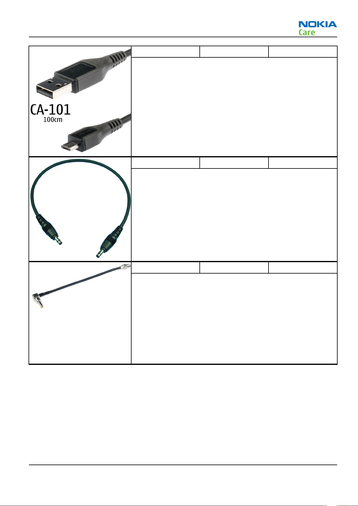
CA-101 Micro USB cable The CA-101 is a USB-to-microUSB data cable that allows connections
between the PC and the phone.
CA-35S Power cable CA-35S is a power cable for connecting, for example, the FPS-10 flash
prommer to the Point-Of-Sales (POS) flash adapter.
CA-58RS RF tuning cable RF tuning cable for use with a flash adapter.
CA-58RS RF cable extends adapter features to allow RF function tests
and RF tuning in GSM bands.
Features include:
• easy to use together with flash adapter or even stand alone
• most accurate RF connection to phone module under test
• most accurate RF connection to phone module under test
• low attenuation and small “ripple” over the width of each GSM band
Note: The RF cable must be used for RF tuning.
Issue 1 COMPANY CONFIDENTIAL Page 2 –15
Copyright © 2007 Nokia. All rights reserved.
Page 36
RM-179; RM-223
Service Tools and Service Concepts
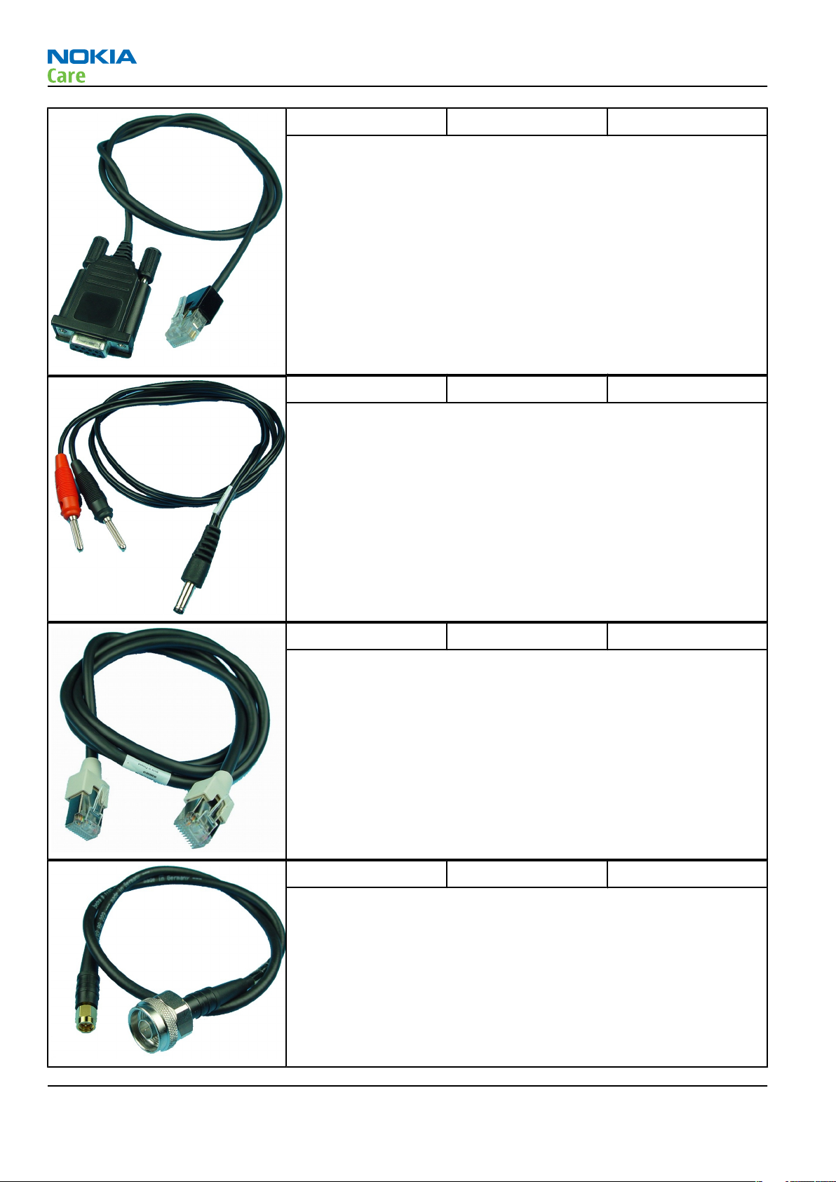
DAU-9S MBUS cable The MBUS cable DAU-9S has a modular connector and is used, for
example, between the PC's serial port and module jigs, flash adapters
or docking station adapters.
Note: Docking station adapters valid for DCT4 products.
PCS-1 Power cable The PCS-1 power cable (DC) is used with a docking station, a module
jig or a control unit to supply a controlled voltage.
XCS-4 Modular cable XCS-4 is a shielded (one specially shielded conductor) modular cable
for flashing and service purposes.
XRF-1 RF cable The RF cable is used to connect, for example, a module repair jig to
the RF measurement equipment.
SMA to N-Connector ca. 610mm.
Attenuation for:
• GSM850/900: 0.3+-0.1 dB
• GSM1800/1900: 0.5+-0.1 dB
• WLAN: 0.6+-0.1dB
Page 2 –16 COMPANY CONFIDENTIAL Issue 1
Copyright © 2007 Nokia. All rights reserved.
Page 37

RM-179; RM-223
Service Tools and Service Concepts
Service concepts
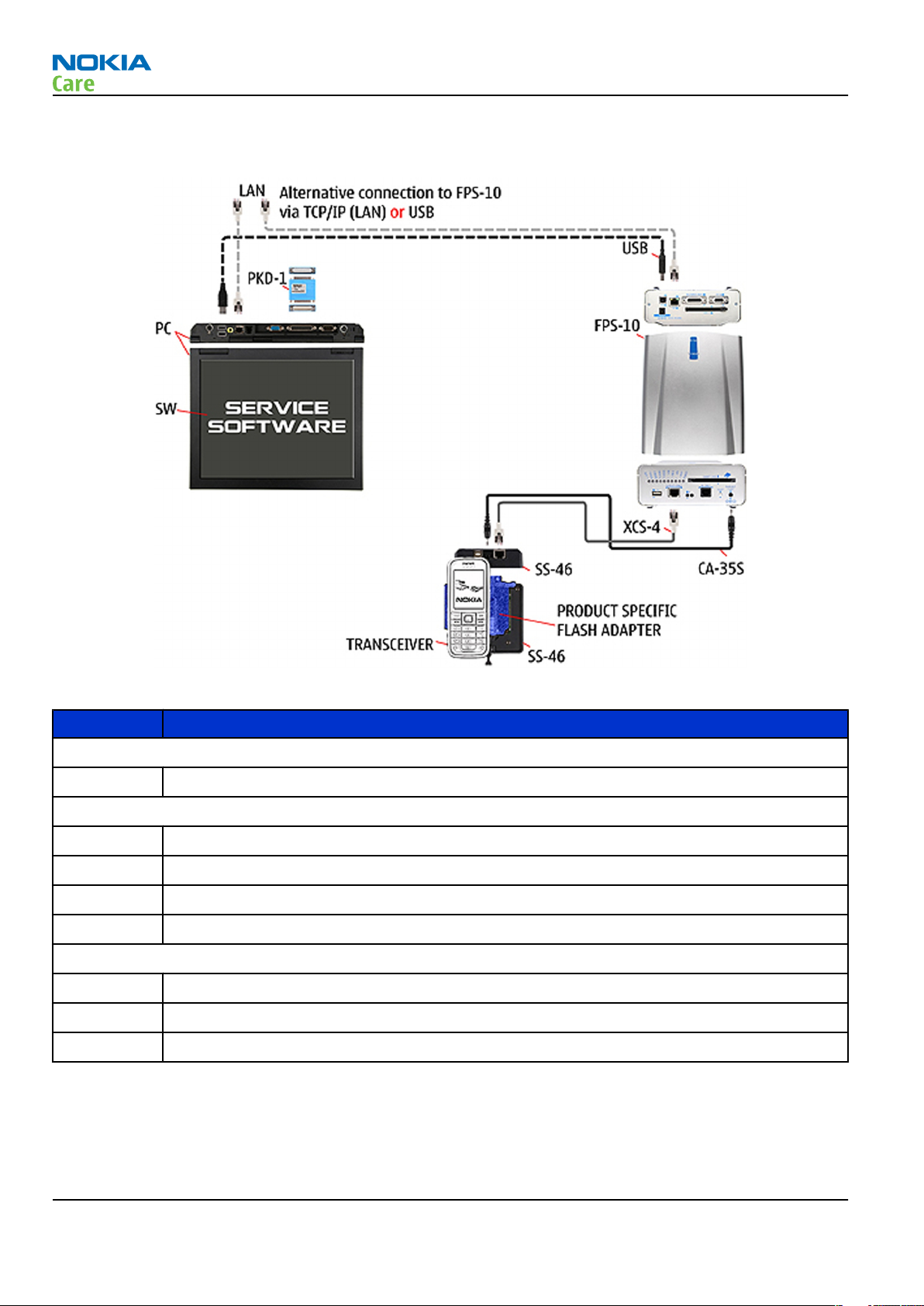
POS (Point of Sale) flash concept
Figure 3 POS flash concept
Type Description
Product specific tools
BP-6MT Battery
Other tools
FLS-5 POS flash dongle
PC with Phoenix service software
Cables
DKE-2 USB connectivity cable
Issue 1 COMPANY CONFIDENTIAL Page 2 –17
Copyright © 2007 Nokia. All rights reserved.
Page 38
Flash concept with FPS-10
RM-179; RM-223
Service Tools and Service Concepts
Figure 4 Basic flash concept with FPS-10
Type Description
Product specific devices
FS-37 Flash adapter
Other devices
FPS-10 Flash prommer box
PKD-1/PK-1 SW security device
SS-46 Interface adapter
PC with Phoenix service software
Cables
XCS-4 Modular cable
CA-35S Power cable
USB cable
Page 2 –18 COMPANY CONFIDENTIAL Issue 1
Copyright © 2007 Nokia. All rights reserved.
Page 39

RM-179; RM-223
Service Tools and Service Concepts
Flash concept with FLS-5 and SS-46
Figure 5 Flash concept with FLS-5 and SS-46
Type Description
Product specific tools
FS-37 Flash adapter
Other tools
FLS-5 POS flash dongle
SS-46 Interface adapter
PC with Phoenix service software
Cables
CA-89DS Cable
Issue 1 COMPANY CONFIDENTIAL Page 2 –19
Copyright © 2007 Nokia. All rights reserved.
Page 40
CU-4 flash concept with FPS-10
RM-179; RM-223
Service Tools and Service Concepts
Figure 6 CU-4 flash concept with FPS-10
Type Description
Product specific devices
FS-37 Flash adapter
Other devices
CU-4 Control unit
FPS-10 Flash prommer box
PKD-1/PK-1 SW security device
SS-62 Flash adapter base
SX-4 Smart card
PC with Phoenix service software
Cables
PCS-1 Power cable
XCS-4 Modular cable
Standard USB cable
USB cable
Page 2 –20 COMPANY CONFIDENTIAL Issue 1
Copyright © 2007 Nokia. All rights reserved.
Page 41

RM-179; RM-223
Service Tools and Service Concepts
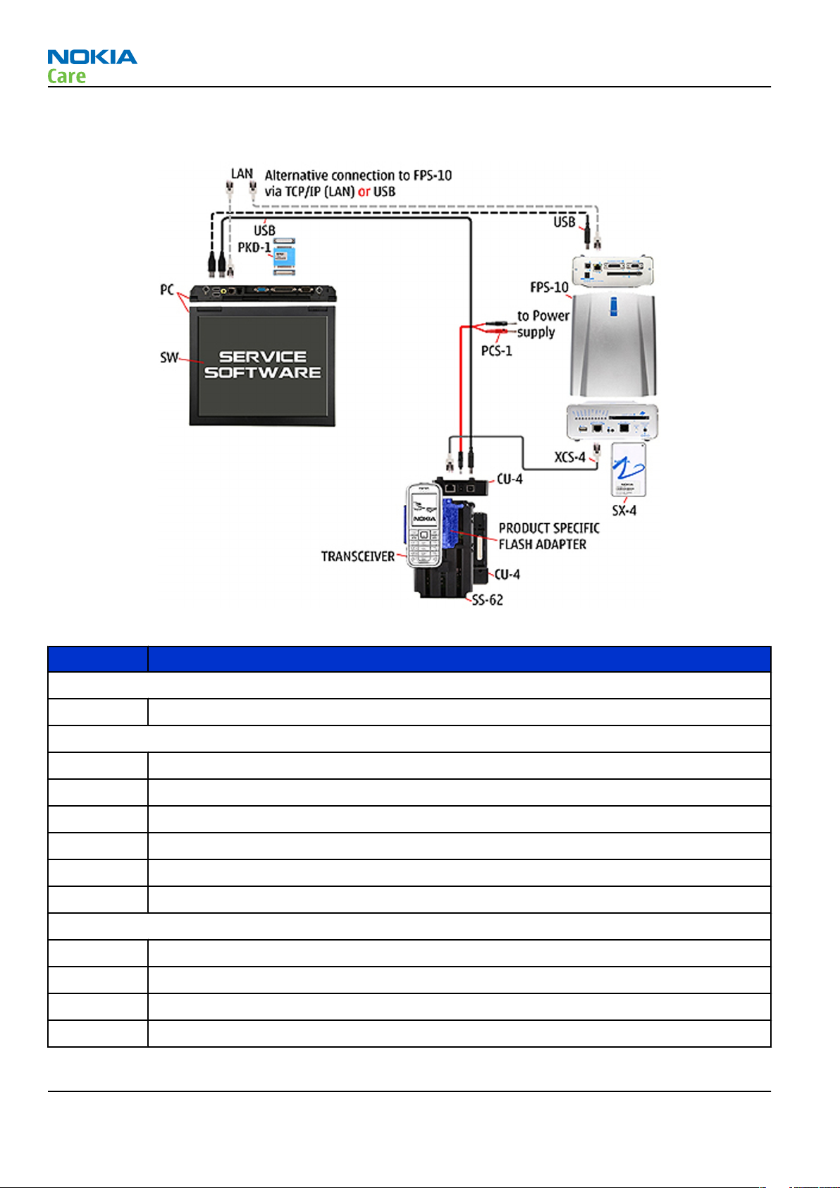
Flash concept with FLS-5 and SS-62
Figure 7 Basic flash concept with FLS-5 and SS-62
Type Description
Product specific tools
FS-37 Flash adapter
Other tools
CU-4 Control unit
FLS-5 POS flash dongle
SS-62 Flash adapter base
PC with Phoenix service software
Cables
CA-89DS Cable
PCS-1 Power cable
Standard USB cable
USB cable
Issue 1 COMPANY CONFIDENTIAL Page 2 –21
Copyright © 2007 Nokia. All rights reserved.
Page 42

Flash concept with FLS-5 and module jig
RM-179; RM-223
Service Tools and Service Concepts
Figure 8 Flash concept with FLS-5 and module jig
Type Description
Product specific tools
MJ-114 Module jig
Other tools
CU-4 Control unit
FLS-5 POS flash dongle
PC with Phoenix service software
Cables
CA-89DS Cable
PCS-1 DC power cable
USB cable
Page 2 –22 COMPANY CONFIDENTIAL Issue 1
Copyright © 2007 Nokia. All rights reserved.
Page 43

RM-179; RM-223
Service Tools and Service Concepts
Module jig service concept
Figure 9 Module jig service concept
Type Description
Phone specific devices
MJ-114 Module jig
Other devices
CU-4 Control unit
FPS-10 Flash prommer box
PKD-1/PK-1 SW security device
SX-4 Smart card
PC with VPOS and Phoenix service software
Measurement equipment
Cables
PCS-1 DC power cable
XCS-4 Modular cable
XRF-1 RF cable
USB cable
Issue 1 COMPANY CONFIDENTIAL Page 2 –23
Copyright © 2007 Nokia. All rights reserved.
Page 44

Type Description
GPIB control cable
Service concept for RF testing and RF/BB tuning
RM-179; RM-223
Service Tools and Service Concepts
Figure 10 Service concept for RF testing and RF/BB tuning
Type Description
Product specific devices
MJ-114 Module jig
Other devices
CU-4 Control unit
PKD-1/PK-1 SW security device
SX-4 Smart card
Measurement equipment
Smart card reader
PC with Phoenix service software
Cables
DAU-9S MBUS cable
PCS-1 DC power cable
Page 2 –24 COMPANY CONFIDENTIAL Issue 1
Copyright © 2007 Nokia. All rights reserved.
Page 45

RM-179; RM-223
Service Tools and Service Concepts
Type Description
XRS-6 RF cable
GPIB control cable
USB cable
RF testing / BB tuning concept
Figure 11 RF testing / BB tuning concept
Type Description
Product specific tools
FS-37 Flash adapter
SA-113 RF coupler
Other tools
CU-4 Control unit
PKD-1/PK-1 SW security device
SS-62 Flash adapter base
SX-4 Smart card
Measurement equipment
Smart card reader
PC with Phoenix service software
Issue 1 COMPANY CONFIDENTIAL Page 2 –25
Copyright © 2007 Nokia. All rights reserved.
Page 46

Type Description
Cables
DAU-9s MBUS cable
PCS-1 DC power cable
XRS-6 RF cable
USB cable
RF/BB tuning and flashing with FPS-10
RM-179; RM-223
Service Tools and Service Concepts
Figure 12 RF/BB tuning and flashing with FPS-10
Type Description
Product specific tools
MJ-114 Module jig
Other tools
CU-4 Control unit
FPS-10 Flash prommer box
PKD-1/PK-1 SW security device
SX-4 Smart card
Measurement equipment
PC with Phoenix service software
Page 2 –26 COMPANY CONFIDENTIAL Issue 1
Copyright © 2007 Nokia. All rights reserved.
Page 47

RM-179; RM-223
Service Tools and Service Concepts
Type Description
Cables
PCS-1 DC power cable
XCS-4 Modular cable
XRS-6 RF cable
USB cable
RF/BB tuning and flashing with FLS-5
Figure 13 RF/BB tuning and flashing with FLS-5
Type Description
Product specific tools
MJ-114 Module jig
Other tools
CU-4 Control unit
FLS-5 POS flash dongle
PKD-1/PK-1 SW security device
SX-4 Smart card
Measurement equipment
PC with Phoenix service software
Issue 1 COMPANY CONFIDENTIAL Page 2 –27
Copyright © 2007 Nokia. All rights reserved.
Page 48

Type Description
Smart card reader
Cables
CA-89DS Cable
PCS-1 DC power cable
XRS-6 RF cable
USB cable
Bluetooth test concept with SB-6
RM-179; RM-223
Service Tools and Service Concepts
Figure 14 Bluetooth test concept with SB-6
Type Description
Product specific tools
FS-37 Flash adapter
Other tools
CU-4 Control unit
PKD-1 SW Security device
SS-62 Generic base adapter
SB-6 BT test box
ACP-8 Charger for SB-6
Cables
PCS-1 Power cable
DAU-9S Cable
Page 2 –28 COMPANY CONFIDENTIAL Issue 1
Copyright © 2007 Nokia. All rights reserved.
Page 49
RM-179; RM-223
Service Tools and Service Concepts
Type Description
PCS-1 DC power cable
Standard USB cable
Issue 1 COMPANY CONFIDENTIAL Page 2 –29
Copyright © 2007 Nokia. All rights reserved.
Page 50

RM-179; RM-223
Service Tools and Service Concepts
(This page left intentionally blank.)
Page 2 –30 COMPANY CONFIDENTIAL Issue 1
Copyright © 2007 Nokia. All rights reserved.
Page 51

Nokia Customer Care
3 — Baseband
Troubleshooting
Issue 1 COMPANY CONFIDENTIAL Page 3 –1
Copyright © 2007 Nokia. All rights reserved.
Page 52

RM-179; RM-223
Baseband Troubleshooting
(This page left intentionally blank.)
Page 3 –2 COMPANY CONFIDENTIAL Issue 1
Copyright © 2007 Nokia. All rights reserved.
Page 53

RM-179; RM-223
Baseband Troubleshooting
Table of Contents
Troubleshooting overview ....................................................................................................................................3–5
Dead or jammed device troubleshooting............................................................................................................3–6
General power checking ........................................................................................................................................3–7
Clocking troubleshooting ......................................................................................................................................3–8
Charging troubleshooting .....................................................................................................................................3–9
Backup battery troubleshooting........................................................................................................................ 3–10
Flash programming fault troubleshooting....................................................................................................... 3–11
Combo memory troubleshooting ...................................................................................................................... 3–13
MicroSD card troubleshooting............................................................................................................................ 3–14
EMMC troubleshooting ........................................................................................................................................ 3–16
USB interface troubleshooting........................................................................................................................... 3–18
SIM card troubleshooting ................................................................................................................................... 3–20
Hall sensor troubleshooting............................................................................................................................... 3–22
WLAN interface troubleshooting ....................................................................................................................... 3–23
Keyboard troubleshooting ................................................................................................................................. 3–24
NaviWheel troubleshooting ............................................................................................................................... 3–26
Power key troubleshooting................................................................................................................................ 3–27
Vibra troubleshooting......................................................................................................................................... 3–28
Display module troubleshooting ....................................................................................................................... 3–29
General instructions for display troubleshooting....................................................................................... 3–29
Display troubleshooting ................................................................................................................................ 3–30
LED driver troubleshooting ........................................................................................................................... 3–31
Power LED troubleshooting .......................................................................................................................... 3–35
Bluetooth and FM radio ...................................................................................................................................... 3–37
Introduction to Bluetooth/FM Radio troubleshooting ............................................................................... 3–37
Bluetooth settings for Phoenix..................................................................................................................... 3–37
Bluetooth self tests in Phoenix..................................................................................................................... 3–38
Bluetooth troubleshooting ........................................................................................................................... 3–40
FM radio troubleshooting.............................................................................................................................. 3–41
Audio troubleshooting........................................................................................................................................ 3–41
Audio troubleshooting test instructions...................................................................................................... 3–41
Internal earpiece troubleshooting ............................................................................................................... 3–45
Internal microphone troubleshooting......................................................................................................... 3–46
IHF speakers troubleshooting....................................................................................................................... 3–47
External microphone troubleshooting......................................................................................................... 3–48
External earpiece troubleshooting............................................................................................................... 3–49
Acoustics troubleshooting............................................................................................................................. 3–50
Introduction to acoustics troubleshooting ............................................................................................ 3–50
Earpiece troubleshooting......................................................................................................................... 3–51
IHF troubleshooting.................................................................................................................................. 3–52
Microphone troubleshooting ................................................................................................................... 3–53
Baseband manual tuning guide......................................................................................................................... 3–54
Certificate restoring for BB5 products.......................................................................................................... 3–54
Energy management calibration.................................................................................................................. 3–60
List of Tables
Table 2 Display module troubleshooting cases................................................................................................ 3–29
Table 3 Pixel defects ........................................................................................................................................... 3–29
Table 4 Calibration value limits ......................................................................................................................... 3–60
Issue 1 COMPANY CONFIDENTIAL Page 3 –3
Copyright © 2007 Nokia. All rights reserved.
Page 54

RM-179; RM-223
Baseband Troubleshooting
List of Figures
Figure 15 Charging backup battery ................................................................................................................... 3–10
Figure 16 Discharging backup battery .............................................................................................................. 3–10
Figure 17 Take single trig measurement for the rise of the BSI signal. ........................................................ 3–12
Figure 18 EMMC initialise .................................................................................................................................... 3–17
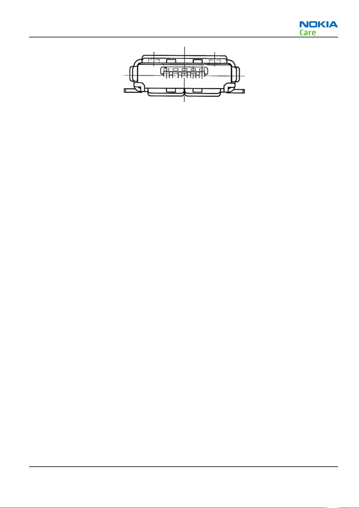
Figure 19 USB connector..................................................................................................................................... 3–19
Figure 20 WLAN alignment targets ................................................................................................................... 3–24
Figure 21 Bluetooth and FM radio component layout..................................................................................... 3–37
Figure 22 BER test result..................................................................................................................................... 3–38
Figure 23 Bluetooth self tests in Phoenix......................................................................................................... 3–39
Figure 24 Single-ended output waveform of the Ext_in_HP_out measurement when earpiece is
connected. ................................................................................................................................................. 3–43
Figure 25 Differential output waveform of the Ext_in_IHF_out out loop measurement when speaker is
connected. ................................................................................................................................................. 3–43
Figure 26 Single-ended output waveform of the Ext_in_Ext_out loop........................................................... 3–43
Figure 27 Single-ended output waveform of the HP_in_Ext_out loop. .......................................................... 3–44
Page 3 –4 COMPANY CONFIDENTIAL Issue 1
Copyright © 2007 Nokia. All rights reserved.
Page 55

RM-179; RM-223
Baseband Troubleshooting
Troubleshooting overview
For practical reasons, troubleshooting is divided into two sections;
• Baseband troubleshooting, including camera, FM radio and Bluetooth.
• RF troubleshooting
Issue 1 COMPANY CONFIDENTIAL Page 3 –5
Copyright © 2007 Nokia. All rights reserved.
Page 56
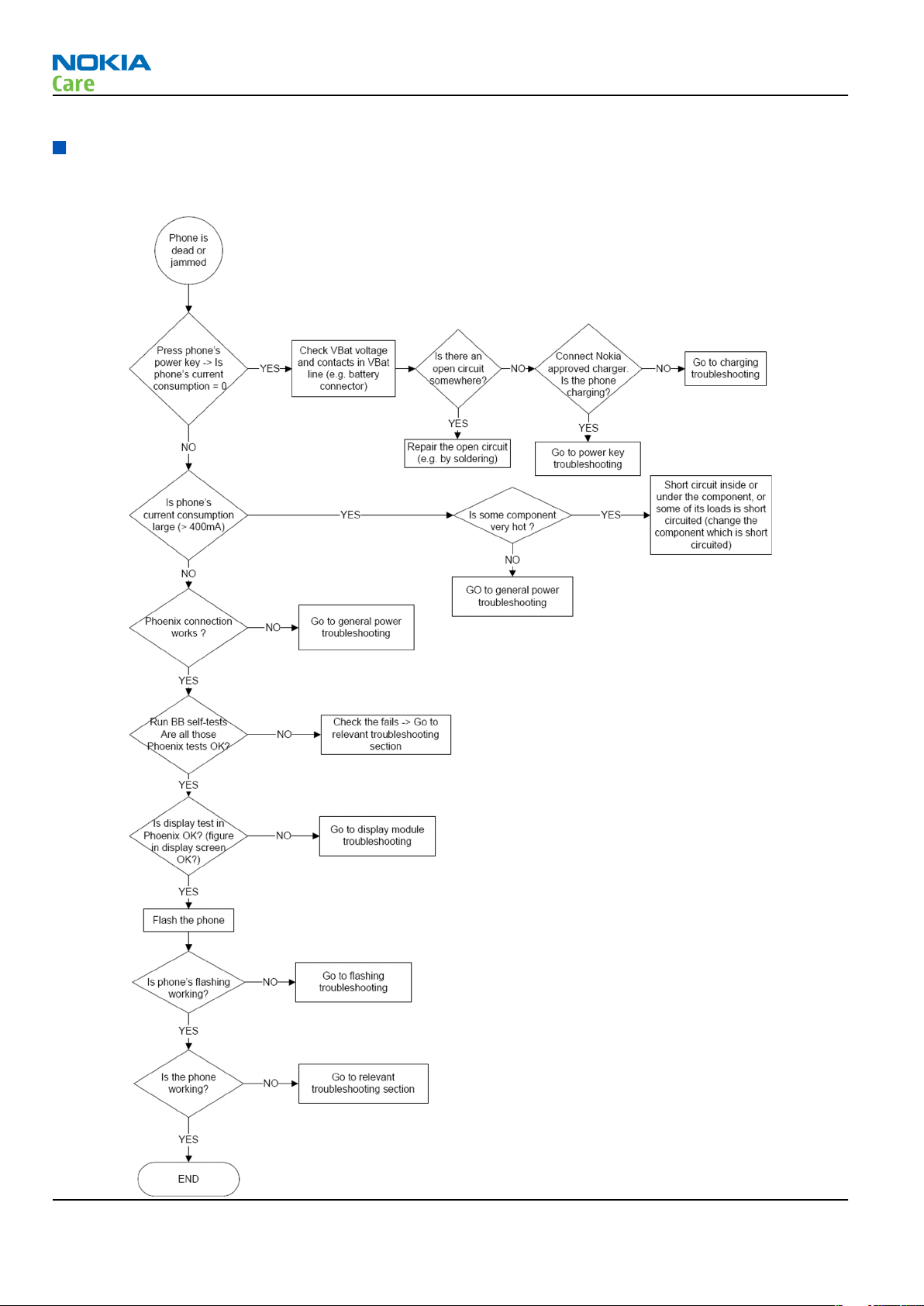
Dead or jammed device troubleshooting
Troubleshooting flow
RM-179; RM-223
Baseband Troubleshooting
Page 3 –6 COMPANY CONFIDENTIAL Issue 1
Copyright © 2007 Nokia. All rights reserved.
Page 57
RM-179; RM-223
Baseband Troubleshooting
General power checking
Check the following voltages:
Signal
name
VIO External
VBACK AVILMA ON ON 2.6 Back-up battery
VSIM1
VSIM2 AVILMA ON ON VBAT3
VDRAM External
VAUX AVILMA OFF OFF 2.78 FM radio, ALS, MR
VANA AVILMA ON ON 2.5 AVILMA VBAT4
VR1 AVILMA OFF ON 2.5 Crystal oscillators VBAT4
VRFC AVILMA ON OFF 1.8 RAPIDO converters
VRCP1 AVILMA 4.75 To RF parts RF active VBATCP
VRCP2 AVILMA 4.75 VBATCP
Regulator Sleep Idle Nominal
voltage
ON ON 1.82 Displays, I/Os
SMPS
N2201
ON ON 1.82 SDRAM
SMPS
N2201
Main user Notes Supply
VBAT5
sensor, displays
VREF AVILMA ON ON 1.35 RF reference
VCORE External
SMPS
N2390
VOUT BETTY OFF OFF 2.5 Audio switch
VCAMANA External
LDO N2501
VCAMDIG External
SMPS
N2500
LEDOUT External
SMPS
N2301
VSD SD
levelshifter
VIO_VILMA AVILMA ON ON 1.82 Audio, BT
ON ON 1.35/1.05
on sleep
2.8 Camera
1.8 Camera, STV984
< 18 Display backlight According
2.9 MicroSD card
RAPIDO digital
core
to
Regulator
spec
Issue 1 COMPANY CONFIDENTIAL Page 3 –7
Copyright © 2007 Nokia. All rights reserved.
Page 58

Clocking troubleshooting
Troubleshooting flow
RM-179; RM-223
Baseband Troubleshooting
Page 3 –8 COMPANY CONFIDENTIAL Issue 1
Copyright © 2007 Nokia. All rights reserved.
Page 59

RM-179; RM-223
Baseband Troubleshooting
Charging troubleshooting
Troubleshooting flow
Issue 1 COMPANY CONFIDENTIAL Page 3 –9
Copyright © 2007 Nokia. All rights reserved.
Page 60

RM-179; RM-223
Baseband Troubleshooting
Backup battery troubleshooting
Verify that the backup battery is empty (U<1V). Switch the phone on. Measure voltage of the battery when
the main battery is connected to the phone and the phone is switched on.
Wait a few minutes and monitor that the backup battery voltage rises. Switch off the phone, disconnect the
main battery and monitor that the voltage of the backup battery decreases. Normal behaviour of the voltage
is described in the figures below.
Figure 15 Charging backup battery
Figure 16 Discharging backup battery
If the voltage rises and falls quickly, check whether either G2200 or C2233 is broken or short-circuited. Backup
battery can be also dead. If the voltage stays ~0V, check resistance VBACK against GND. If there is no short
circuit, AVILMA is faulty. Replace AVILMA.
Page 3 –10 COMPANY CONFIDENTIAL Issue 1
Copyright © 2007 Nokia. All rights reserved.
Page 61

RM-179; RM-223
Baseband Troubleshooting
Flash programming fault troubleshooting
Part 1
Issue 1 COMPANY CONFIDENTIAL Page 3 –11
Copyright © 2007 Nokia. All rights reserved.
Page 62

Part 2
RM-179; RM-223
Baseband Troubleshooting
Figure 17 Take single trig measurement for the rise of the BSI signal.
Page 3 –12 COMPANY CONFIDENTIAL Issue 1
Copyright © 2007 Nokia. All rights reserved.
Page 63

RM-179; RM-223
Baseband Troubleshooting
Combo memory troubleshooting
Troubleshooting flow
Issue 1 COMPANY CONFIDENTIAL Page 3 –13
Copyright © 2007 Nokia. All rights reserved.
Page 64

MicroSD card troubleshooting
Troubleshooting flow
RM-179; RM-223
Baseband Troubleshooting
Page 3 –14 COMPANY CONFIDENTIAL Issue 1
Copyright © 2007 Nokia. All rights reserved.
Page 65
RM-179; RM-223
Baseband Troubleshooting
Issue 1 COMPANY CONFIDENTIAL Page 3 –15
Copyright © 2007 Nokia. All rights reserved.
Page 66

EMMC troubleshooting
Troubleshooting flow
RM-179; RM-223
Baseband Troubleshooting
Page 3 –16 COMPANY CONFIDENTIAL Issue 1
Copyright © 2007 Nokia. All rights reserved.
Page 67

RM-179; RM-223
Baseband Troubleshooting
Figure 18 EMMC initialise
Issue 1 COMPANY CONFIDENTIAL Page 3 –17
Copyright © 2007 Nokia. All rights reserved.
Page 68

USB interface troubleshooting
Troubleshooting flow
RM-179; RM-223
Baseband Troubleshooting
Page 3 –18 COMPANY CONFIDENTIAL Issue 1
Copyright © 2007 Nokia. All rights reserved.
Page 69
RM-179; RM-223
Baseband Troubleshooting
Figure 19 USB connector
Issue 1 COMPANY CONFIDENTIAL Page 3 –19
Copyright © 2007 Nokia. All rights reserved.
Page 70

SIM card troubleshooting
Troubleshooting flow
RM-179; RM-223
Baseband Troubleshooting
Page 3 –20 COMPANY CONFIDENTIAL Issue 1
Copyright © 2007 Nokia. All rights reserved.
Page 71
RM-179; RM-223
Baseband Troubleshooting
Issue 1 COMPANY CONFIDENTIAL Page 3 –21
Copyright © 2007 Nokia. All rights reserved.
Page 72
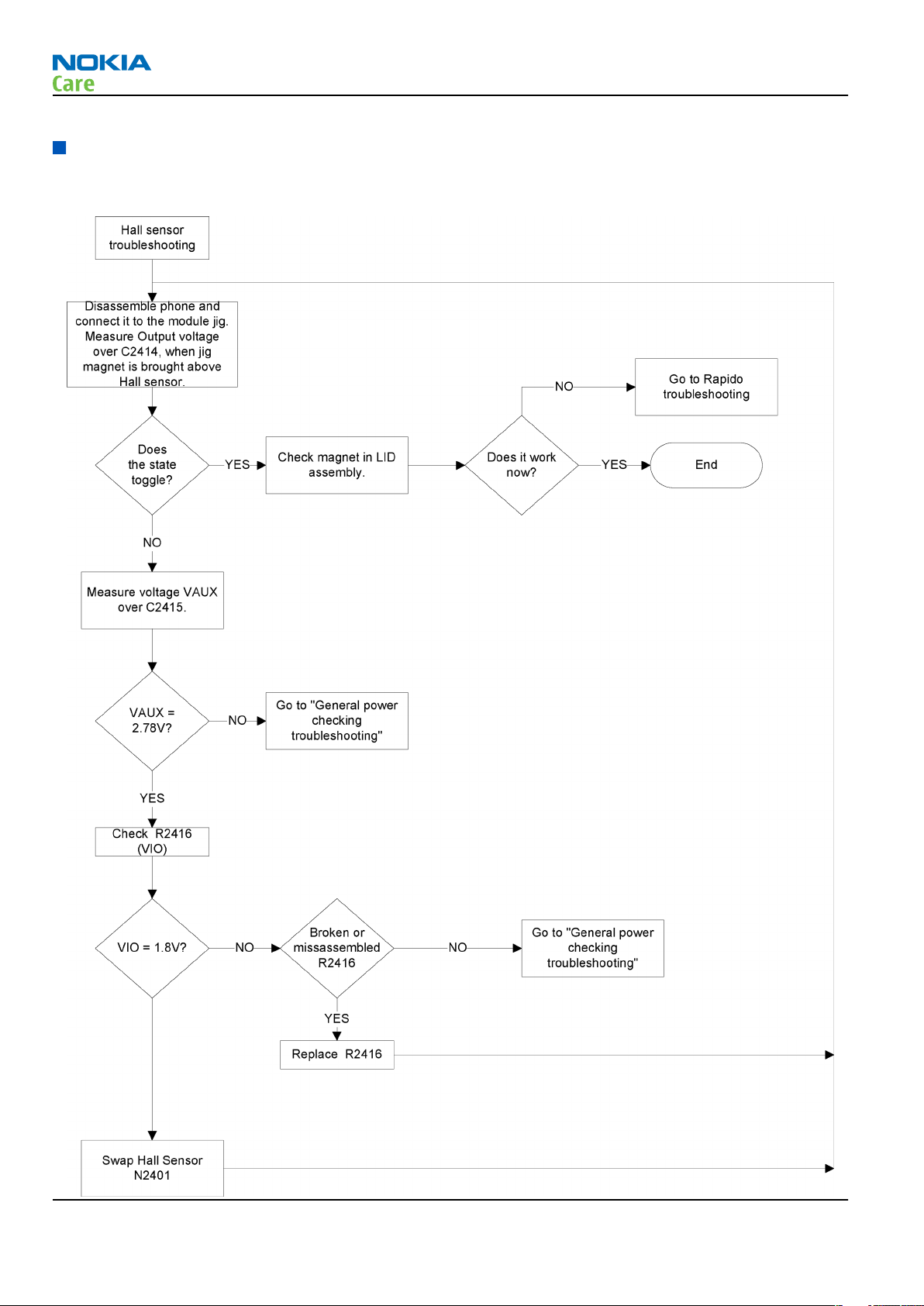
Hall sensor troubleshooting
Troubleshooting flow
RM-179; RM-223
Baseband Troubleshooting
Page 3 –22 COMPANY CONFIDENTIAL Issue 1
Copyright © 2007 Nokia. All rights reserved.
Page 73
RM-179; RM-223
Baseband Troubleshooting
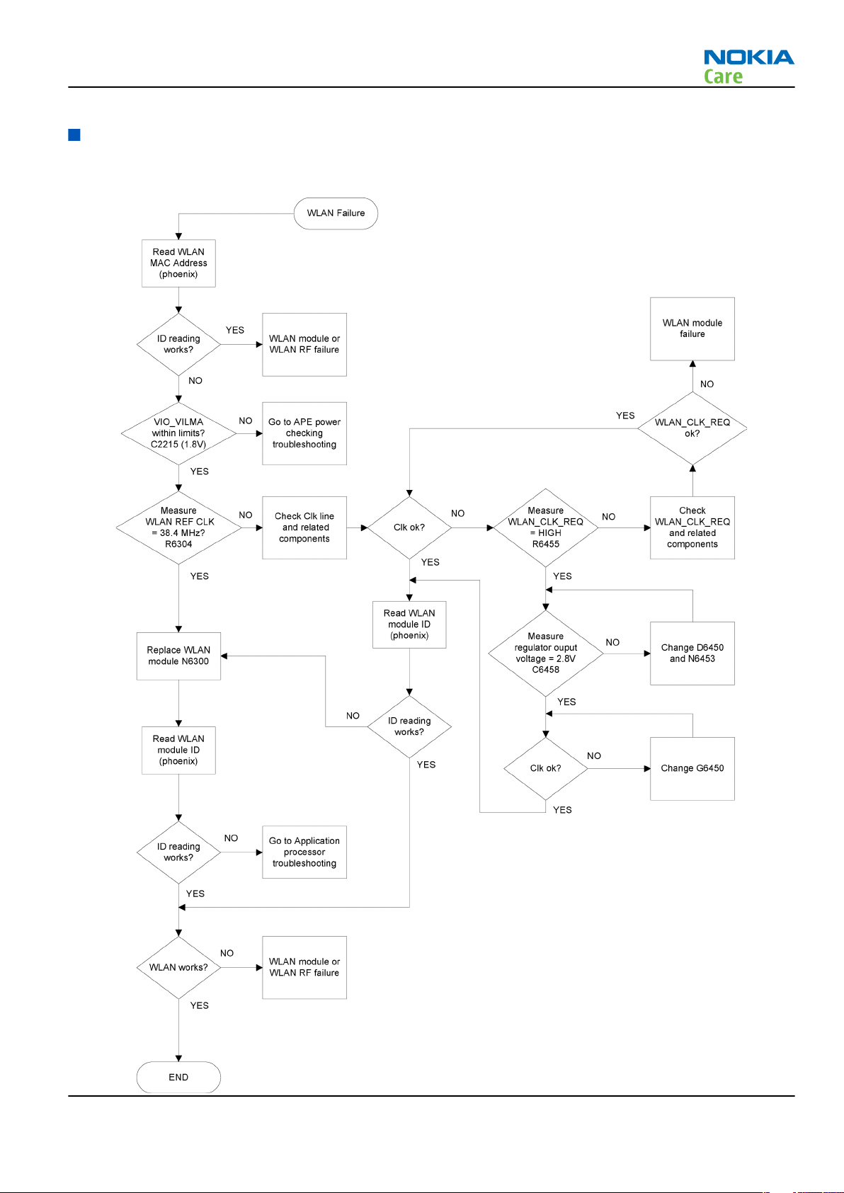
WLAN interface troubleshooting
Troubleshooting flow
Issue 1 COMPANY CONFIDENTIAL Page 3 –23
Copyright © 2007 Nokia. All rights reserved.
Page 74

Figure 20 WLAN alignment targets
RM-179; RM-223
Baseband Troubleshooting
Keyboard troubleshooting
Context
There are two possible failure modes in the keyboard module:
• One or more keys can be stuck, so that the key does not react when a keydome is pressed. This kind of
failure is caused by mechanical reasons (dirt, rust).
• Malfunction of several keys at the same time; this happens when one or more rows or columns are failing
(shortcut or open connection). For a more detailed description of the keyboard and keymatrix, see section
Keyboard.
If the failure mode is not clear, start with the Keyboard Test in Phoenix.
Page 3 –24 COMPANY CONFIDENTIAL Issue 1
Copyright © 2007 Nokia. All rights reserved.
Page 75

RM-179; RM-223
Baseband Troubleshooting
Troubleshooting flow
Issue 1 COMPANY CONFIDENTIAL Page 3 –25
Copyright © 2007 Nokia. All rights reserved.
Page 76

NaviWheel troubleshooting
Troubleshooting flow
RM-179; RM-223
Baseband Troubleshooting
Page 3 –26 COMPANY CONFIDENTIAL Issue 1
Copyright © 2007 Nokia. All rights reserved.
Page 77

RM-179; RM-223
Baseband Troubleshooting
Power key troubleshooting
Troubleshooting flow
Issue 1 COMPANY CONFIDENTIAL Page 3 –27
Copyright © 2007 Nokia. All rights reserved.
Page 78

Vibra troubleshooting
Troubleshooting flow
RM-179; RM-223
Baseband Troubleshooting
Page 3 –28 COMPANY CONFIDENTIAL Issue 1
Copyright © 2007 Nokia. All rights reserved.
Page 79

RM-179; RM-223
Baseband Troubleshooting
Display module troubleshooting
General instructions for display troubleshooting
Context
• The display is in a normal mode when the phone is in active use.
• The display is off when the phone is in the screen saver mode. Then power LED is active.
• The operating modes of the display can be controlled with the help of
Table 2 Display module troubleshooting cases
Display blank There is no image on the display. The display looks
the same when the phone is on as it does when the
phone is off. The backlight can be on in some cases.
Image on the display not correct Image on the display can be corrupted or a part of
the image can be missing. If a part of the image is
missing, change the display module. If the image is
otherwise corrupted, follow the appropriate
troubleshooting diagram.
Phoenix
.
Backlight dim or not working at all Backlight LED components are inside the display
module. Backlight failure cause can also be in the
display connector, 70pol engine connector, the
SliderFlex or in the backlight power source in the
main engine of the phone.
This means that in case the display is working
(image OK), the backlight is faulty.
Visual defects (pixel) Pixel defects can be checked by controlling the
display with Phoenix. Use both colours, black and
white, on a full screen.
The display may have some random pixel defects
that are acceptable for this type of display. The
criteria when pixel defects are regarded as a display
failure, resulting in a replacement of the display, are
presented the following table.
Table 3 Pixel defects
Item White dot defect Black dot
defect
1 Defect counts R G B White Dot
Total
1 1
Total
1 1 1 1
2 Combined
defect counts
Issue 1 COMPANY CONFIDENTIAL Page 3 –29
Not allowed.
Two single dot defects that are within 5 mm of each other should be
interpreted as combined dot defect.
Copyright © 2007 Nokia. All rights reserved.
Page 80

RM-179; RM-223
Baseband Troubleshooting
Steps
1. Verify with a working SlideModule that the fault is not the SliderFlex.
2. Verify with a working display that the fault is not on the display module itself.
The display module cannot be repaired.
3. Check that the cellular engine is working normally.
i To check the functionality, connect the phone to a docking station.
ii Start
iii Read the phone information to check that also the application engine is functioning normally (you
4. Proceed to the display troubleshooting flowcharts.
Use the Display Test tool in
Phoenix
should be able to read the APE ID).
service software.
Phoenix
to find the detailed fault mode.
Display troubleshooting
Context
Before going to display troubleshooting flow, make sure that the engine is working and starting up correctly.
If the problem is in the engine, go to baseband troubleshooting.
Page 3 –30 COMPANY CONFIDENTIAL Issue 1
Copyright © 2007 Nokia. All rights reserved.
Page 81

RM-179; RM-223
Baseband Troubleshooting
Troubleshooting flow
Issue 1 COMPANY CONFIDENTIAL Page 3 –31
Copyright © 2007 Nokia. All rights reserved.
Page 82

RM-179; RM-223
Baseband Troubleshooting
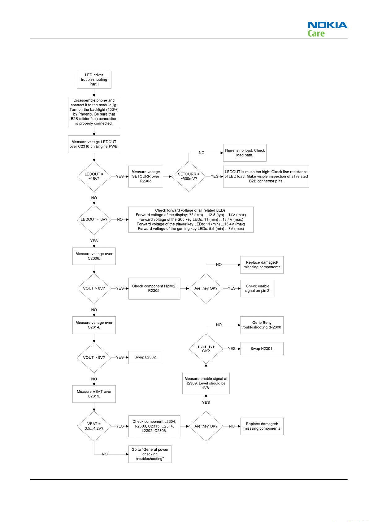
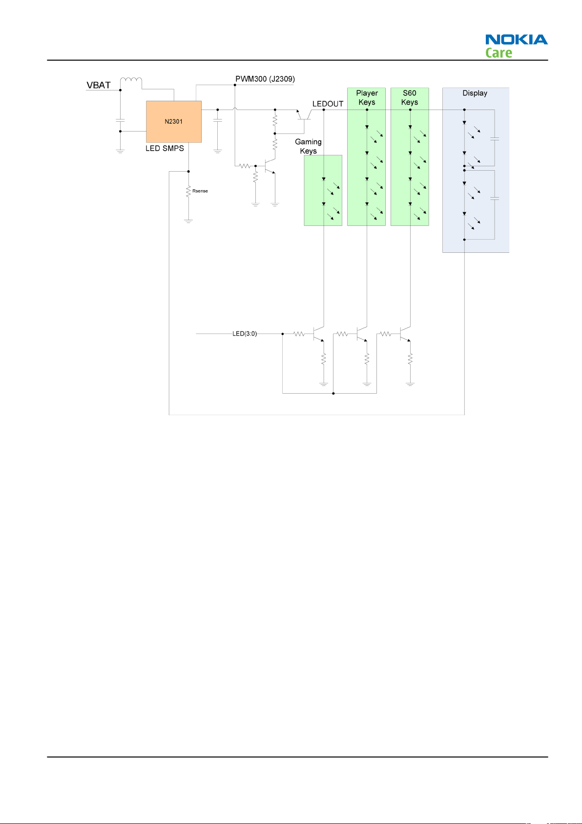
LED driver troubleshooting
Context
The phone has three illumination drivers. One of them provides the LED current for the display, the menu
keys and the gaming keys. One other provides the LED current for ITU-keyboard and side keys.
The third one provides the FlashLED current. For instructions for troubleshooting this driver, see Flash LED
troubleshooting (page 5–13).
Page 3 –32 COMPANY CONFIDENTIAL Issue 1
Copyright © 2007 Nokia. All rights reserved.
Page 83
RM-179; RM-223
Baseband Troubleshooting
LED driver troubleshooting part 1
Issue 1 COMPANY CONFIDENTIAL Page 3 –33
Copyright © 2007 Nokia. All rights reserved.
Page 84
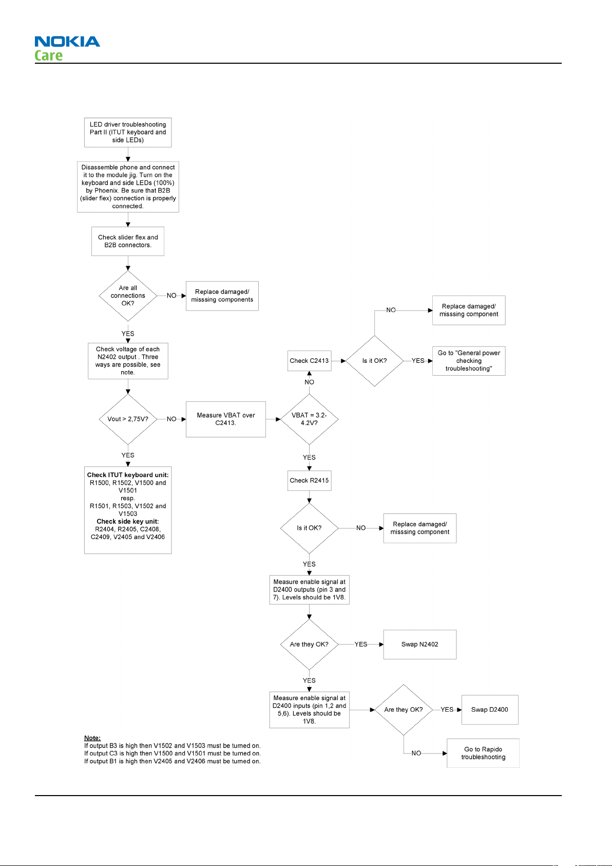
LED driver troubleshooting part 2
RM-179; RM-223
Baseband Troubleshooting
Page 3 –34 COMPANY CONFIDENTIAL Issue 1
Copyright © 2007 Nokia. All rights reserved.
Page 85
RM-179; RM-223
Baseband Troubleshooting
Issue 1 COMPANY CONFIDENTIAL Page 3 –35
Copyright © 2007 Nokia. All rights reserved.
Page 86
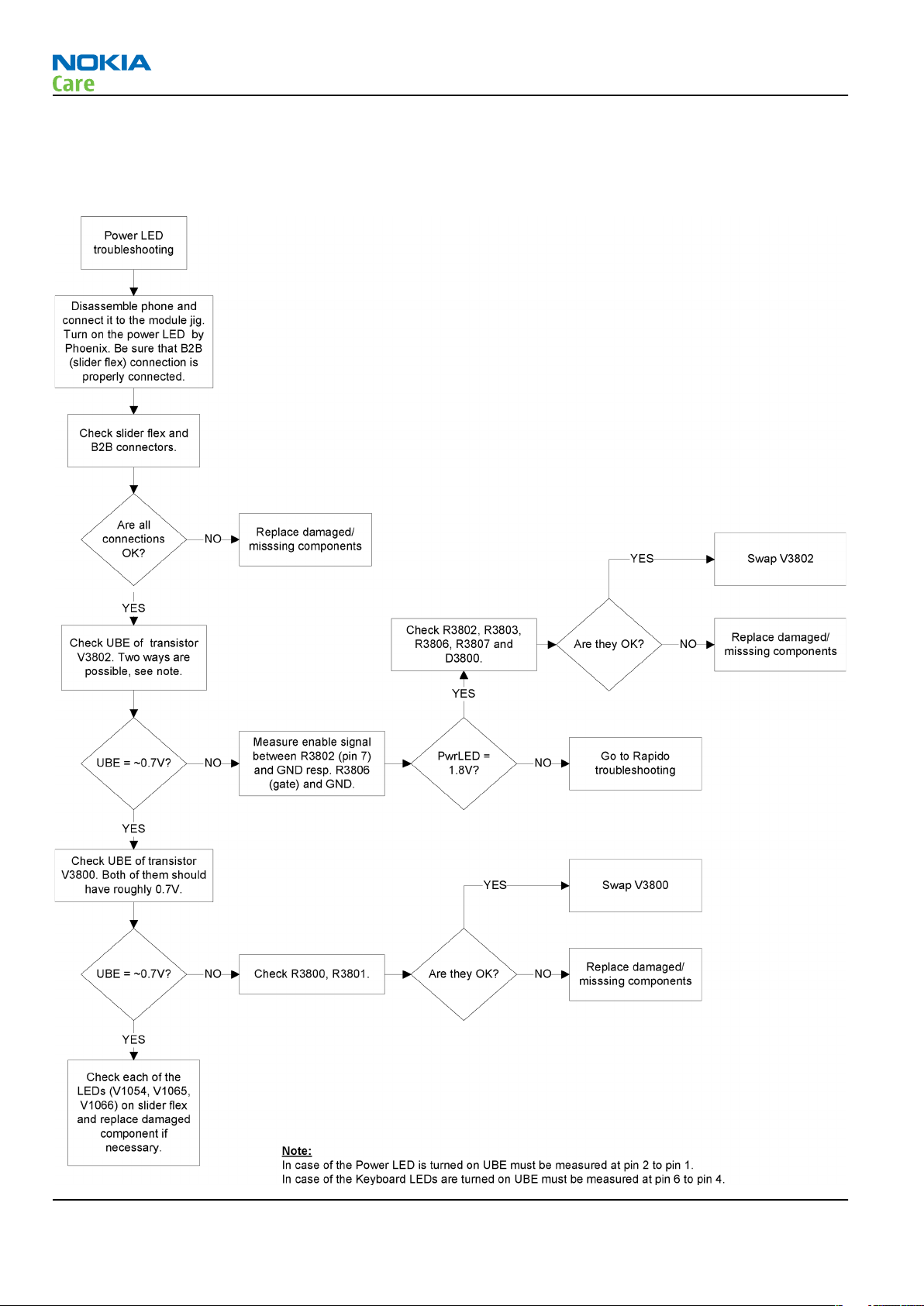
Power LED troubleshooting
Troubleshooting flow
RM-179; RM-223
Baseband Troubleshooting
Page 3 –36 COMPANY CONFIDENTIAL Issue 1
Copyright © 2007 Nokia. All rights reserved.
Page 87
RM-179; RM-223
Baseband Troubleshooting
Bluetooth and FM radio
Introduction to Bluetooth/FM Radio troubleshooting
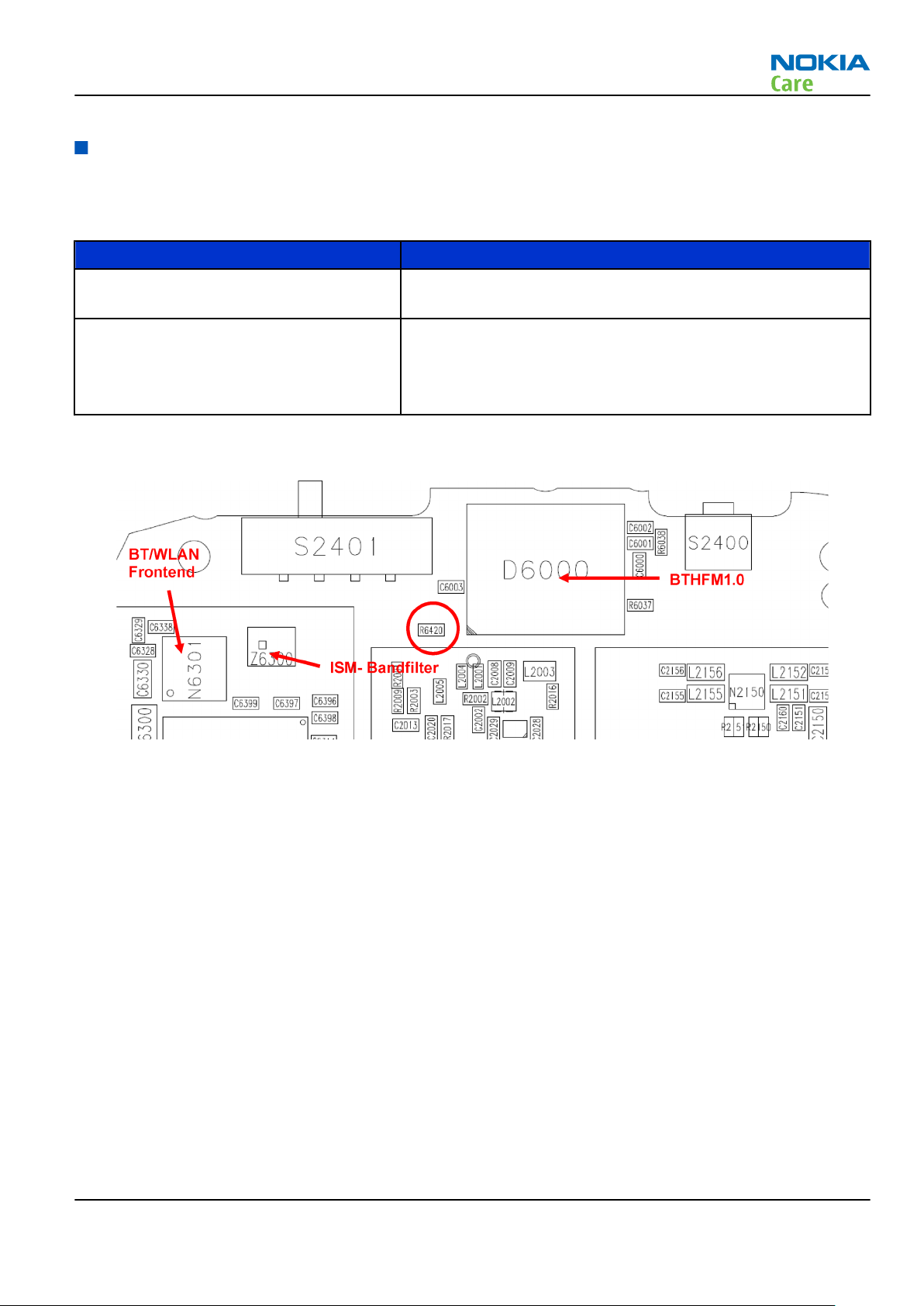
Bluetooth problems that can occur:
Problem Description
A malfunction in the BT ASIC, BB ASICs or
Phone’s BT SMD components.
No BT link can be established. • Bad contact of c-clips (X6302, X6300) to the corresponding
This could have many causes i.e. SW or HW related.
antenna pads.
• Damaged component or bad contact of R6420 (0 Ohm), BT/
WLAN frontend (N6301) or ISM band filter (Z6300).
Bluetooth/FM Radio component layout
Figure 21 Bluetooth and FM radio component layout
Bluetooth settings for Phoenix
Steps
1. Start
2. From the File menu, choose Open Product, and then choose the correct type designator from the
3. Place the phone to a flash adapter in the local mode.
4. Choose Testing→Bluetooth LOCALS .
5. Locate JBT-9’s serial number (12 digits) found in the type label on the back of JBT-9.
6. In the
7. Place the JBT-9 box near (within 10 cm) the BT antenna and click Run BER Test.
Phoenix
Product list.
In addition to JBT-9, also SB-6, JBT-3 and JBT-6 Bluetooth test boxes can be used.
Bluetooth LOCALS
Counterpart BT Device Address line.
This needs to be done only once provided that JBT-9 is not changed.
service software.
window, write the 12-digit serial number on the
Results
Bit Error Rate test result is displayed in the
Bit Error Rate (BER) Tests
pane in the
Bluetooth LOCALS
window.
Issue 1 COMPANY CONFIDENTIAL Page 3 –37
Copyright © 2007 Nokia. All rights reserved.
Page 88

RM-179; RM-223
Baseband Troubleshooting
Figure 22 BER test result
Bluetooth self tests in Phoenix
Steps
1. Start
2. ChooseFile→Scan Product.
3. Place the phone to a flash adapter.
4. From the Mode drop-down menu, set mode to Local.
5. Choose Testing→Self Tests.
6. In the
Phoenix
Self Tests
• ST_LPRF_IF_TEST
• ST_LPRF_AUDIO_LINES_TEST
• ST_BT_WAKEUP_TEST
service software.
window check the following Bluetooth related tests:
Page 3 –38 COMPANY CONFIDENTIAL Issue 1
Copyright © 2007 Nokia. All rights reserved.
Page 89

RM-179; RM-223
Baseband Troubleshooting
7. To run the tests, click Start.
Figure 23 Bluetooth self tests in
Phoenix
Issue 1 COMPANY CONFIDENTIAL Page 3 –39
Copyright © 2007 Nokia. All rights reserved.
Page 90

Bluetooth troubleshooting
Troubleshooting flow
RM-179; RM-223
Baseband Troubleshooting
Page 3 –40 COMPANY CONFIDENTIAL Issue 1
Copyright © 2007 Nokia. All rights reserved.
Page 91

RM-179; RM-223
Baseband Troubleshooting
FM radio troubleshooting
Troubleshooting flow
Audio troubleshooting
Audio troubleshooting test instructions
Single ended external earpiece and differential internal earpiece/IHF outputs can be measured either with a
single ended or a differential probe.
When measuring single ended, each output is measured against ground.
Note: Do not connect ground of single ended probe to 2nd signal of differential lines.
Internal handsfree output is measured using a current probe, if a special low-pass filter designed for
measuring a digital amplifier is not available. Note also, that when using a current probe, input signal
frequency must be set to 2kHz.
The signal for input is single ended.
Required equipment
The following equipment is needed for the tests:
Issue 1 COMPANY CONFIDENTIAL Page 3 –41
Copyright © 2007 Nokia. All rights reserved.
Page 92

RM-179; RM-223
Baseband Troubleshooting
• Oscilloscope
• Function generator (sine waveform)
• Current probe (Internal handsfree PWM output measurement)
• Phoenix service software
• Power supply 3.7V
Test procedure
Ausio can be tested using Phoenix audio routings option. Four different audio loop paths can be activated:
• External mic to external earpiece
• External mic to internal earpiece
• External mic to internal handsfree speaker (IHF, mono signal to both speakers)
• Internal mic to external earpiece
Each audio loop sets routing from the specified input to the specified output enabling a quick in-out test.
Loop path gains are fixed an can not be changed using phoenix. Correct pins an signals for each test see
following table.
Phoenix audio loop tests and test results
The results presented in the table apply, when no accessory is connected. Earpiece, internal mic and speaker
are in place during measurement. Applying a headset accessory during measurement causes a significant
drop in measured levels.
The gain values presented in table apply for differential output vs single ended input.
Loop test Input
terminal
Ext Mic ->
Ext Earp
Ext Mic ->
Int Earp
Ext Mic ->
Int Hands
Free
Int Mic ->
Int Hands
Free
HS-MIC &
GND
HS-MIC &
GND
XMICP &
GND
XMICN &
GND
Acoustica
l input,
1khz sine
wave
Output
terminal
HSEARL&GND-8.6 1000 367 1,2
HSEARR&
GND
EarP &
GND
EarN &
GND
B2150
B2151 all
terminals
IHF
Speakerp
ad
Path gain
[dB] fixed
-10 1000 310 1,2
8,5 920 2520 0 ~25mA
Input
Voltage
[mVpp]
94 dB SPL -
Differenti
al
outputvol
tage
[mVpp]
Output DC
level [V]
Output
current
each
Measurement data
Earpiece signal
Page 3 –42 COMPANY CONFIDENTIAL Issue 1
Copyright © 2007 Nokia. All rights reserved.
Page 93

RM-179; RM-223
Baseband Troubleshooting
Figure 24 Single-ended output waveform of the Ext_in_HP_out measurement when earpiece is connected.
Integrated handsfree signal
Figure 25 Differential output waveform of the Ext_in_IHF_out out loop measurement when speaker is connected.
External output from AV
Figure 26 Single-ended output waveform of the Ext_in_Ext_out loop.
Issue 1 COMPANY CONFIDENTIAL Page 3 –43
Copyright © 2007 Nokia. All rights reserved.
Page 94

External output from AV (acoustic input)
Figure 27 Single-ended output waveform of the HP_in_Ext_out loop.
RM-179; RM-223
Baseband Troubleshooting
Page 3 –44 COMPANY CONFIDENTIAL Issue 1
Copyright © 2007 Nokia. All rights reserved.
Page 95

RM-179; RM-223
Baseband Troubleshooting
Internal earpiece troubleshooting
Troubleshooting flow
Issue 1 COMPANY CONFIDENTIAL Page 3 –45
Copyright © 2007 Nokia. All rights reserved.
Page 96
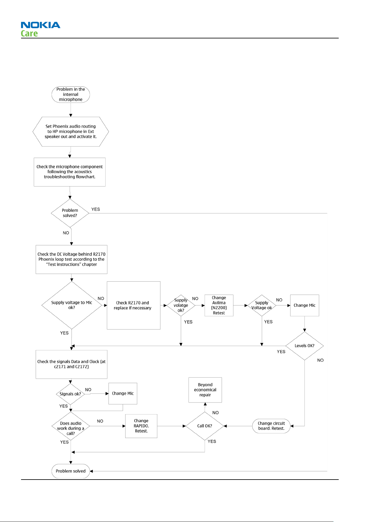
Internal microphone troubleshooting
Troubleshooting flow
RM-179; RM-223
Baseband Troubleshooting
Page 3 –46 COMPANY CONFIDENTIAL Issue 1
Copyright © 2007 Nokia. All rights reserved.
Page 97
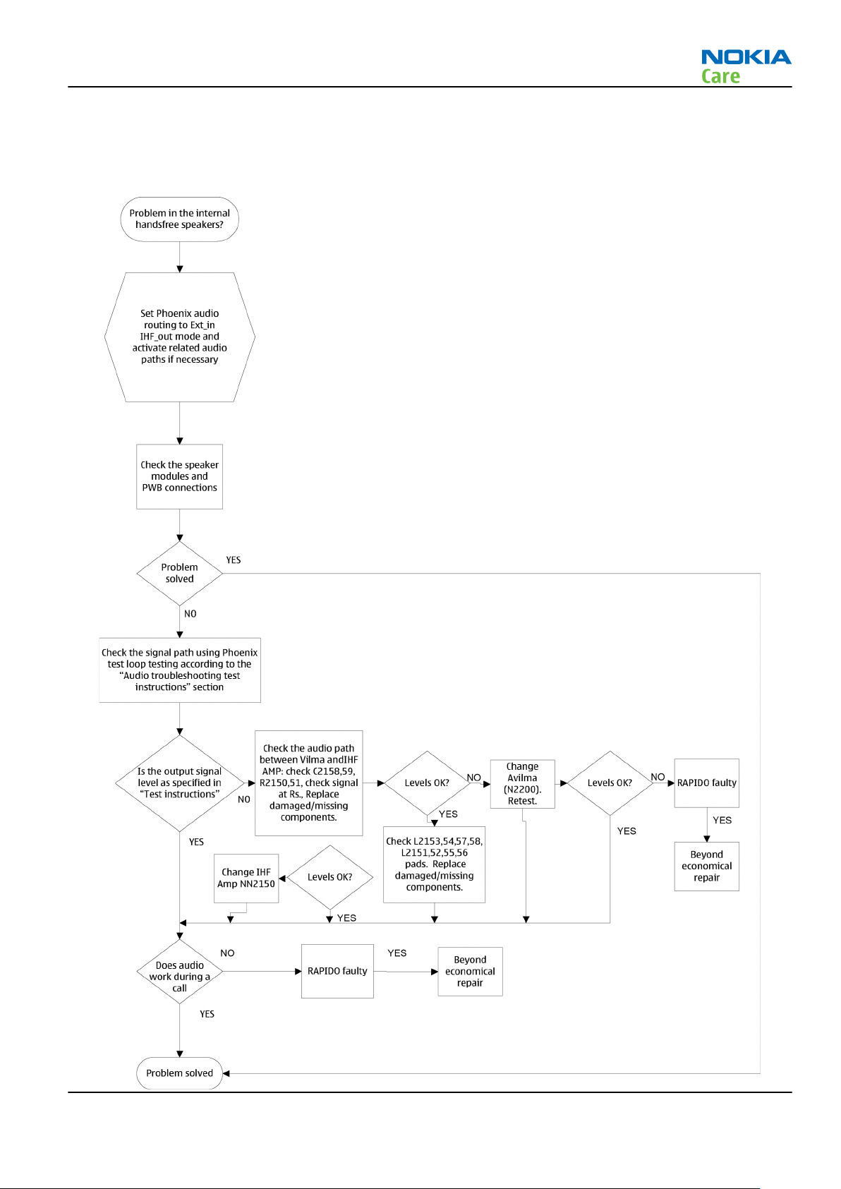
RM-179; RM-223
Baseband Troubleshooting
IHF speakers troubleshooting
Troubleshooting flow
Issue 1 COMPANY CONFIDENTIAL Page 3 –47
Copyright © 2007 Nokia. All rights reserved.
Page 98
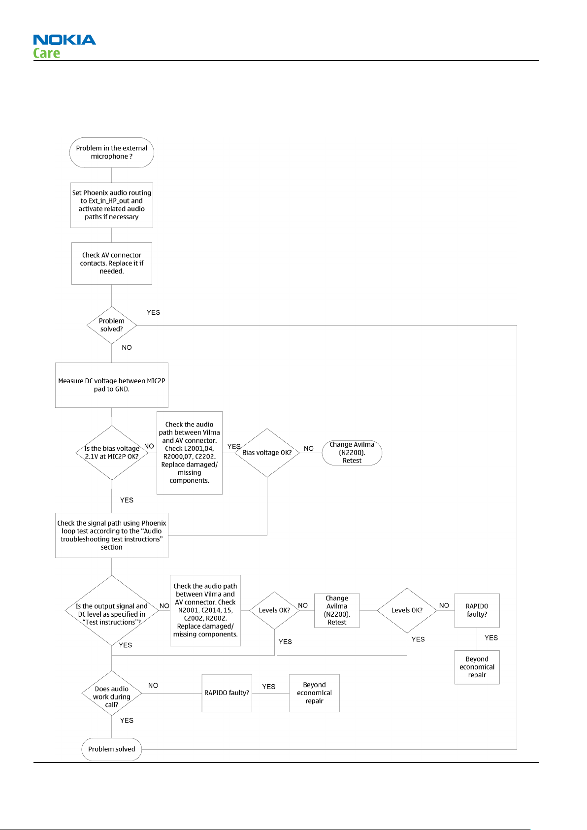
External microphone troubleshooting
Troubleshooting flow
RM-179; RM-223
Baseband Troubleshooting
Page 3 –48 COMPANY CONFIDENTIAL Issue 1
Copyright © 2007 Nokia. All rights reserved.
Page 99
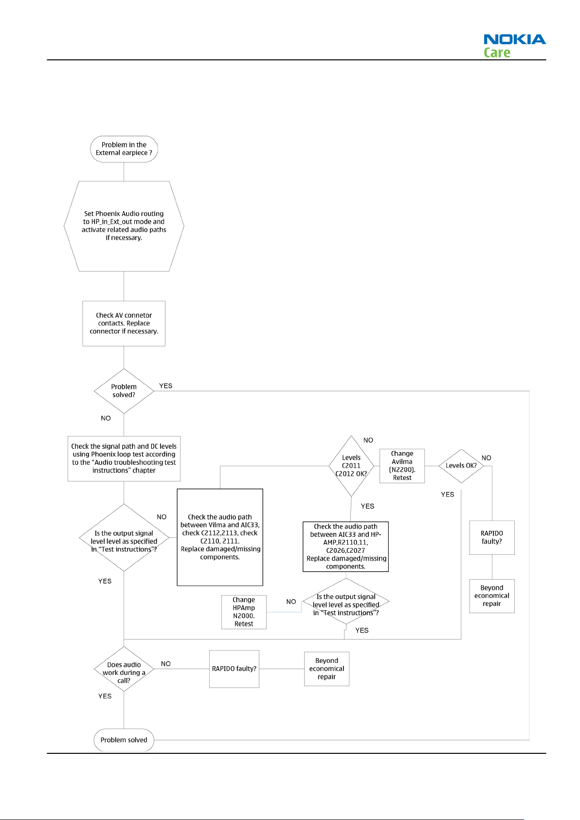
RM-179; RM-223
Baseband Troubleshooting
External earpiece troubleshooting
Troubleshooting flow
Issue 1 COMPANY CONFIDENTIAL Page 3 –49
Copyright © 2007 Nokia. All rights reserved.
Page 100

RM-179; RM-223
Baseband Troubleshooting
Acoustics troubleshooting
Introduction to acoustics troubleshooting
Acoustics design ensures that the sound is detected correctly with a microphone and properly radiated to
the outside of the device by speaker(s). The acoustics of the phone includes three basic systems: earpiece,
Integrated Hands Free (IHF) and microphone.
The sound reproduced from the earpiece readiates through a single hole on the front cover (A-cover). The
sound reproduced from the IHF speakers radiates from left and right sound holes located on both sides of
the device. Microphone is located at the bottom, next to the system connector.
For a correct functionality of the phone, all sound holes must be always open. When the phone is used, care
must be taken not to close any of those holes with a hand or fingers. The phone should be dry and clean,
and no objects must be located in such a way that they close any of the holes.
Page 3 –50 COMPANY CONFIDENTIAL Issue 1
Copyright © 2007 Nokia. All rights reserved.
 Loading...