

Page 1

Nokia Customer Care
Service Manual
RM-135 (Nokia N76)
Mobile Terminal
Part No: 9203082 (Issue 1)
COMPANY CONFIDENTIAL
Copyright © 2007 Nokia. All rights reserved.
Page 2

RM-135
Nokia Customer Care Amendment Record Sheet
Amendment Record Sheet
Amendment No Date Inserted By Comments
Issue 1 03/2007 MHa
Page ii COMPANY CONFIDENTIAL Issue 1
Copyright © 2007 Nokia. All rights reserved.
Page 3

RM-135
Copyright Nokia Customer Care
Copyright
Copyright © 2007 Nokia. All rights reserved.
Reproduction, transfer, distribution or storage of part or all of the contents in this document in any form
without the prior written permission of Nokia is prohibited.
Nokia, Nokia Connecting People, and Nokia X and Y are trademarks or registered trademarks of Nokia
Corporation. Other product and company names mentioned herein may be trademarks or tradenames of
their respective owners.
Nokia operates a policy of continuous development. Nokia reserves the right to make changes and
improvements to any of the products described in this document without prior notice.
Under no circumstances shall Nokia be responsible for any loss of data or income or any special, incidental,
consequential or indirect damages howsoever caused.
The contents of this document are provided "as is". Except as required by applicable law, no warranties of
any kind, either express or implied, including, but not limited to, the implied warranties of merchantability
and fitness for a particular purpose, are made in relation to the accuracy, reliability or contents of this
document. Nokia reserves the right to revise this document or withdraw it at any time without prior notice.
The availability of particular products may vary by region.
IMPORTANT
This document is intended for use by qualified service personnel only.
Issue 1 COMPANY CONFIDENTIAL Page iii
Copyright © 2007 Nokia. All rights reserved.
Page 4

RM-135
Nokia Customer Care Warnings and cautions
Warnings and cautions
Warnings
• IF THE DEVICE CAN BE INSTALLED IN A VEHICLE, CARE MUST BE TAKEN ON INSTALLATION IN VEHICLES FITTED
WITH ELECTRONIC ENGINE MANAGEMENT SYSTEMS AND ANTI-SKID BRAKING SYSTEMS. UNDER CERTAIN FAULT
CONDITIONS, EMITTED RF ENERGY CAN AFFECT THEIR OPERATION. IF NECESSARY, CONSULT THE VEHICLE DEALER/
MANUFACTURER TO DETERMINE THE IMMUNITY OF VEHICLE ELECTRONIC SYSTEMS TO RF ENERGY.
• THE PRODUCT MUST NOT BE OPERATED IN AREAS LIKELY TO CONTAIN POTENTIALLY EXPLOSIVE ATMOSPHERES,
FOR EXAMPLE, PETROL STATIONS (SERVICE STATIONS), BLASTING AREAS ETC.
• OPERATION OF ANY RADIO TRANSMITTING EQUIPMENT, INCLUDING CELLULAR TELEPHONES, MAY INTERFERE
WITH THE FUNCTIONALITY OF INADEQUATELY PROTECTED MEDICAL DEVICES. CONSULT A PHYSICIAN OR THE
MANUFACTURER OF THE MEDICAL DEVICE IF YOU HAVE ANY QUESTIONS. OTHER ELECTRONIC EQUIPMENT MAY
ALSO BE SUBJECT TO INTERFERENCE.
• BEFORE MAKING ANY TEST CONNECTIONS, MAKE SURE YOU HAVE SWITCHED OFF ALL EQUIPMENT.
Cautions
• Servicing and alignment must be undertaken by qualified personnel only.
• Ensure all work is carried out at an anti-static workstation and that an anti-static wrist strap is worn.
• Ensure solder, wire, or foreign matter does not enter the telephone as damage may result.
• Use only approved components as specified in the parts list.
• Ensure all components, modules, screws and insulators are correctly re-fitted after servicing and
alignment.
• Ensure all cables and wires are repositioned correctly.
• During testing never activate the GSM transmitter without a proper antenna load, otherwise GSM PA may
be damaged.
Page iv COMPANY CONFIDENTIAL Issue 1
Copyright © 2007 Nokia. All rights reserved.
Page 5

RM-135
ESD protection Nokia Customer Care
ESD protection
Nokia requires that service points have sufficient ESD protection (against static electricity) when servicing
the phone.
Any product of which the covers are removed must be handled with ESD protection. The SIM card can be
replaced without ESD protection if the product is otherwise ready for use.
To replace the covers ESD protection must be applied.
All electronic parts of the product are susceptible to ESD. Resistors, too, can be damaged by static electricity
discharge.
All ESD sensitive parts must be packed in metallized protective bags during shipping and handling outside
any ESD Protected Area (EPA).
Every repair action involving opening the product or handling the product components must be done under
ESD protection.
ESD protected spare part packages MUST NOT be opened/closed out of an ESD Protected Area.
For more information and local requirements about ESD protection and ESD Protected Area, contact your local
Nokia After Market Services representative.
Issue 1 COMPANY CONFIDENTIAL Page v
Copyright © 2007 Nokia. All rights reserved.
Page 6

RM-135
Nokia Customer Care Care and maintenance
Care and maintenance
This product is of superior design and craftsmanship and should be treated with care. The suggestions below
will help you to fulfil any warranty obligations and to enjoy this product for many years.
• Keep the phone and all its parts and accessories out of the reach of small children.
• Keep the phone dry. Precipitation, humidity and all types of liquids or moisture can contain minerals that
will corrode electronic circuits.
• Do not use or store the phone in dusty, dirty areas. Its moving parts can be damaged.
• Do not store the phone in hot areas. High temperatures can shorten the life of electronic devices, damage
batteries, and warp or melt certain plastics.
• Do not store the phone in cold areas. When it warms up (to its normal temperature), moisture can form
inside, which may damage electronic circuit boards.
• Do not drop, knock or shake the phone. Rough handling can break internal circuit boards.
• Do not use harsh chemicals, cleaning solvents, or strong detergents to clean the phone.
• Do not paint the phone. Paint can clog the moving parts and prevent proper operation.
• Use only the supplied or an approved replacement antenna. Unauthorised antennas, modifications or
attachments could damage the phone and may violate regulations governing radio devices.
All of the above suggestions apply equally to the product, battery, charger or any accessory.
Page vi COMPANY CONFIDENTIAL Issue 1
Copyright © 2007 Nokia. All rights reserved.
Page 7

RM-135
Company Policy Nokia Customer Care
Company Policy
Our policy is of continuous development; details of all technical modifications will be included with service
bulletins.
While every endeavour has been made to ensure the accuracy of this document, some errors may exist. If
any errors are found by the reader, NOKIA MOBILE PHONES Business Group should be notified in writing/email.
Please state:
• Title of the Document + Issue Number/Date of publication
• Latest Amendment Number (if applicable)
• Page(s) and/or Figure(s) in error
Please send to:
NOKIA CORPORATION
Nokia Mobile Phones Business Group
Nokia Customer Care
PO Box 86
FIN-24101 SALO
Finland
E-mail: Service.Manuals@nokia.com
Issue 1 COMPANY CONFIDENTIAL Page vii
Copyright © 2007 Nokia. All rights reserved.
Page 8

RM-135
Nokia Customer Care Battery information
Battery information
Note: A new battery's full performance is achieved only after two or three complete charge and
discharge cycles!
The battery can be charged and discharged hundreds of times but it will eventually wear out. When the
operating time (talk-time and standby time) is noticeably shorter than normal, it is time to buy a new battery.
Use only batteries approved by the phone manufacturer and recharge the battery only with the chargers
approved by the manufacturer. Unplug the charger when not in use. Do not leave the battery connected to
a charger for longer than a week, since overcharging may shorten its lifetime. If left unused a fully charged
battery will discharge itself over time.
Temperature extremes can affect the ability of your battery to charge.
For good operation times with Ni-Cd/NiMh batteries, discharge the battery from time to time by leaving the
product switched on until it turns itself off (or by using the battery discharge facility of any approved accessory
available for the product). Do not attempt to discharge the battery by any other means.
Use the battery only for its intended purpose.
Never use any charger or battery which is damaged.
Do not short-circuit the battery. Accidental short-circuiting can occur when a metallic object (coin, clip or
pen) causes direct connection of the + and - terminals of the battery (metal strips on the battery) for example
when you carry a spare battery in your pocket or purse. Short-circuiting the terminals may damage the battery
or the connecting object.
Leaving the battery in hot or cold places, such as in a closed car in summer or winter conditions, will reduce
the capacity and lifetime of the battery. Always try to keep the battery between 15°C and 25°C (59°F and 77°
F). A phone with a hot or cold battery may temporarily not work, even when the battery is fully charged.
Batteries' performance is particularly limited in temperatures well below freezing.
Do not dispose of batteries in a fire!
Dispose of batteries according to local regulations (e.g. recycling). Do not dispose as household waste.
Page viii COMPANY CONFIDENTIAL Issue 1
Copyright © 2007 Nokia. All rights reserved.
Page 9

RM-135
Nokia N76 Service Manual Structure Nokia Customer Care
Nokia N76 Service Manual Structure
1 General Information
2 Service Software Instructions
3 Service Tools and Service Concepts
4 BB Troubleshooting and Manual Tuning Guide
5 RF troubleshooting
6 Camera Module Troubleshooting
7 System Module and User Interface
Glossary
Issue 1 COMPANY CONFIDENTIAL Page ix
Copyright © 2007 Nokia. All rights reserved.
Page 10

RM-135
Nokia Customer Care Nokia N76 Service Manual Structure
(This page left intentionally blank.)
Page x COMPANY CONFIDENTIAL Issue 1
Copyright © 2007 Nokia. All rights reserved.
Page 11

Nokia Customer Care
1 — General Information
Issue 1 COMPANY CONFIDENTIAL Page 1 –1
Copyright © 2007 Nokia. All rights reserved.
Page 12

RM-135
Nokia Customer Care General Information
(This page left intentionally blank.)
Page 1 –2 COMPANY CONFIDENTIAL Issue 1
Copyright © 2007 Nokia. All rights reserved.
Page 13

RM-135
General Information Nokia Customer Care
Table of Contents
Product selection....................................................................................................................................................1–5
Product features and sales package.....................................................................................................................1–6
Product and module list ........................................................................................................................................1–8
Mobile enhancements............................................................................................................................................1–8
Technical specifications...................................................................................................................................... 1–10
Transceiver general specifications ............................................................................................................... 1–10
Main RF characteristics for GSM850/900/1800/1900 and WCDMA2100 phones ...................................... 1–10
Battery endurance.......................................................................................................................................... 1–11
List of Figures
Figure 1 RM-135 phone..........................................................................................................................................1–5
Issue 1 COMPANY CONFIDENTIAL Page 1 –3
Copyright © 2007 Nokia. All rights reserved.
Page 14

RM-135
Nokia Customer Care General Information
(This page left intentionally blank.)
Page 1 –4 COMPANY CONFIDENTIAL Issue 1
Copyright © 2007 Nokia. All rights reserved.
Page 15
RM-135
General Information Nokia Customer Care
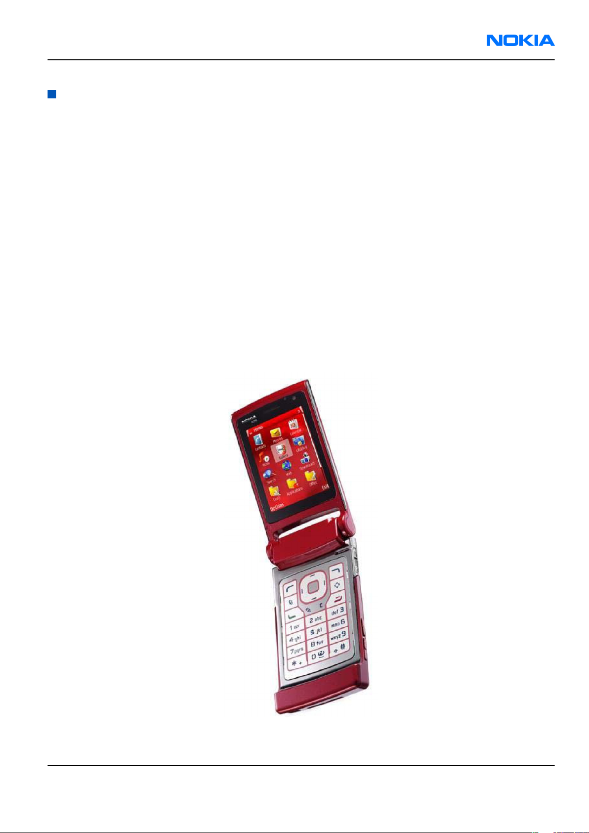
Product selection
RM-135 is a WCDMA/GSM dual mode handportable phone. It supports EGSM850/900/1800/1900 and
WCDMA2100.
RM-135 is a 3GPP Release 4 terminal supporting CSD/HCSD, GPRS/EGPRS and WCDMA data bearers. For WCDMA
the maximum bit rate is up to 384 kbps for downlink and 384 kbps for uplink with simultaneous CS speech
or CS video (max. 64 kbps).
For 2G and 2.5G networks the RM-135 is a Class B EGPRS MSC 32, which means a in maximum download speed
of up to 296kbit/s with EGPRS, and up to 107kbit/s with GPRS. According to GSM standard 05.05 it responds
to class 4 (max. 2W) in GSM 850 and EGSM 900, class 1 (1W) is DCS 1800, and class 1 in PCS 1900.
RM-135 supports Bluetooth 2.0 + EDR standard and two-way video calls with two integrated cameras, on the
front and one on the back. The main camera is an integrated 2 Megapixel camera with a digital zoom and
the secondary CIF camera is for video calls.
RM-135 is an MMS (Multimedia Messaging Service) enabled multimedia device. The MMS implementation
follows the OMA MMS standard release 1.2. It has a large 2.4’’ QVGA (320x240 pixels) TFT main display with
16 million colors, and a smaller 1,36” (128x160 pixels) TFT secondary display with 262k colors.
The HTML browser is a highly advanced internet browser also capable of viewing operator domain XHTML
Mobile Profile (MP) content.
RM-135 uses Symbian 9.x (S60) operating system and supports also MIDP Java 2.0, providing a good platform
for compelling 3rd party applications.
Figure 1 RM-135 phone
Issue 1 COMPANY CONFIDENTIAL Page 1 –5
Copyright © 2007 Nokia. All rights reserved.
Page 16

RM-135
Nokia Customer Care General Information
Product features and sales package
Imaging
Main camera:
• Sensor: CMOS, 2 megapixel
• F number/Aperture: F2.8
• Focal length: 4.4 mm
• Focus range: 40 cm to infinity
• Capture modes: still, video and sequenece
Video:
• Video resolutions: 320x240, 176x144 and 128x96
• Video clip length: 30 sec short mode or 1 hour free mode
• Video file format: .3GPP (*.3gp)
• White balance: automatic, sunny, cloudy, incandescent, fluorescent
• Colour tone: normal, sepia, B&W, vivid, negative
• Zoom (digital): 4x
Photo:
• Still image resolutions: 1600x1200, 1152x864 and 640x480
• Still image file format: EXIF (JPEG), *.jpg
• Exposure control: automatic
• White balance: automatic, sunny, cloudy, incandescent, fluorescent
• Colour tone: normal, sepia, B&W, vivid, negative
• Self-timer: 10, 20, 30 s
• Flash settings: Auto, off and forced
• Zoom (digital): 4x
Other camera features
• LED flash and red LED recording indicator
• Front camera, CIF (128x160 pixels) sensor
Music
• Digital music player: supports eAAC+/MP3//M4A/WMA with playlists
• Cover UI music keys
• OMA DRM 2.0 support for music
• Stereo FM radio (87.0-108 MHz)
• Integrated stereo handsfree speaker
• Stereo headset HS-43 with ECI control
Media
• Real-time video sharing
• Video streaming
• HTML browser over HTTP/TCP/IP stack
Page 1 –6 COMPANY CONFIDENTIAL Issue 1
Copyright © 2007 Nokia. All rights reserved.
Page 17

RM-135
General Information Nokia Customer Care
• Visual Radio™ support
Productivity
Messaging:
• OMA MMS 1.2, AMR and 3GGP SMIL Player
• Text to speech functionality (SMS reader)
Office applications:
• Push E-mail with support for attachments
Personal Information Management (PIM):
• Contacts, calendar, to-do, notes, calculator, clock
Synchronization:
• Local/Remote (using SyncML)
• Data: Calendar, Contacts, To-do, notes, E-mail
• PC Applications: Microsoft Outlook (2000, 2002, 2003), Outlook Express, Lotus Organizer (5.0, 6.0), Lotus
Notes (5.0, 6.0)
Call management:
• Call logs, speed dial, enhanced voice dialling, voice commands
• Nokia Push to Talk (PoC)
Connectivity
• Mini USB interface with USB 2.0 Full speed
• 3.5mm AV connector
• Bluetooth wireless technology 2.0
Add-on software framework
• Symbian 9.x OS
• Nokia Series 60, 3rd edition, feature pack 3.1
• Java: MIDP2.0
Additional technical specifications
• Vibrating alert
• 3GPP Rel 4compliant
• Speech codecs supported in WCDMA: AMR
• Speech codecs supported in GSM: AMR, EFR, FR
• WCDMA HSDPA 2100 MHz with simultaneous voice and packet data (PS max speed DL/UL= 384kbps/
384kbps, CS max speed 64kbps)
• Dual Transfer Mode (DTM) support for simultaneous voice and packet data connection in GSM/EDGE
networks. Simple class A, multi slot class 11, max speed DL/UL: 236.8/177.6kbits/s
• EGPRS class B, multi slot class 32, (5 Rx + 3 Tx / max sum 6), max speed DL/UL= 296 / 177.6 kbits/s)
• GPRS class B, multi slot class 32 (5 Rx + 3 Tx / max sum 6), max speed DL/UL= 107 / 64.2 kbits/s)
Sales package
• Transceiver RM-135
• Charger (AC-5)
Issue 1 COMPANY CONFIDENTIAL Page 1 –7
Copyright © 2007 Nokia. All rights reserved.
Page 18
RM-135
Nokia Customer Care General Information
• Battery (BL-4B)
• Stereo headset with ECI (HS-43)
• Mini USB connectivity cable (DKE-2)
• CD ROM
• User Guide
• Quick Guide
• Sales carton
Product and module list
Module name Type code Notes
System/RF module 1SE Main PWB with components.
Upper block module 1SH
Camera PWB 1SG
UI flex module 1SF
Mobile enhancements
Data
Enhancement Type
Connectivity cable DKE-2
MicroSD card MU-26 (128 MB)
MU-27 (256 MB)
MU-28 (512 MB)
MU-22 (1 GB)
MU-37 (2 GB)
Power
Enhancement Type
Battery 700mAh BL-4B
Compact charger AC-3
Travel charger AC-4
Charging adapter CA-44
Audio
Enhancement Type
Stereo headset HS-43
HS-48
Page 1 –8 COMPANY CONFIDENTIAL Issue 1
Copyright © 2007 Nokia. All rights reserved.
Page 19
RM-135
General Information Nokia Customer Care
Enhancement Type
Music headset HS-45
AD-43
Headset HS-41
Wireless headset HS-4W
HDW-3
HS-26W
HS-11W
HS-36W
HS-37W
Wireless clip-on headset HS-21W
Bluetooth headset BH-200
BH-300
BH-600
BH-301
BH-302
BH-801
BH-202
BH-700
BH-800
BH-900
TTY adapter HDA-12
Messaging
Enhancement Type
Wireless keyboard SU-8W
Digital pen SU-1B
SU-27W
Music
Enhancement Type
Music headphones HS-61
Advanced music headphones HS-62
Mini speakers MD-4
Music speakers MD-3
Issue 1 COMPANY CONFIDENTIAL Page 1 –9
Copyright © 2007 Nokia. All rights reserved.
Page 20
RM-135
Nokia Customer Care General Information
Positioning
Enhancement Type
Wireless GPS module LD-3W
LD-1W
Car
Enhancement Type
Wireless plug-in car handsfree HF-6W
HF-35W
HF-33W
Advanced car kit CK-7W
Multimedia car kit CK-20W
Car kit Nokia 616
Universal holder CR-39
Holder easy mount HH-12
Mobile charger DC-4
GPS module LD-2
Technical specifications
Transceiver general specifications
Unit Dimensions (L x W x T) (mm) Weight (g)
Transceiver with BL-4B
700mAh li-ion battery
106,5 x 52 x 13,7 115 70
Volume (cm3)
Main RF characteristics for GSM850/900/1800/1900 and WCDMA2100 phones
Parameter Unit
Cellular system GSM850, EGSM900, GSM1800/1900, or WCDMA2100
Rx frequency band GSM850: 869 - 894MHz
EGSM900: 925 - 960 MHz
GSM1800: 1805 - 1880 MHz
GSM1900: 1930 - 1990 MHz
WCDMA2100: 2110 - 2170 MHz
Page 1 –10 COMPANY CONFIDENTIAL Issue 1
Copyright © 2007 Nokia. All rights reserved.
Page 21
RM-135
General Information Nokia Customer Care
Parameter Unit
Tx frequency band GSM850: 824 - 849MHz
EGSM900: 880 - 915 MHz
GSM1800: 1710 - 1785 MHz
GSM1900: 1850 - 1910 MHz
WCDMA2100: 1920 - 1980 MHz
Output power GSM850: +5 ...+33dBm/3.2mW ... 2W
GSM900: +5 … +33dBm/3.2mW … 2W
GSM1800: +0 … +30dBm/1.0mW … 1W
GSM1900: +0 … +30dBm/1.0mW … 1W
WCDMA -50 … 24 dBm
Number of RF channels GSM850: 124
GSM900: 174
GSM1800: 374
GSM1900: 299
Channel spacing 200 kHz
Number of Tx power levels GSM850: 15
GSM900: 15
GSM1800: 16
GSM1900: 16
Battery endurance
Battery Talk time Stand-by Video call time Music playback
BL-4B 700 mAh up to 120 / 165
minutes (WCDMA /
GSM )
up to 8.5 / 8.5 days
(WCDMA / GSM )
Charging times
time
up to 75 minutes up to 8 hours
(offline mode )
AC-4
70 minutes
Issue 1 COMPANY CONFIDENTIAL Page 1 –11
Copyright © 2007 Nokia. All rights reserved.
Page 22

RM-135
Nokia Customer Care General Information
(This page left intentionally blank.)
Page 1 –12 COMPANY CONFIDENTIAL Issue 1
Copyright © 2007 Nokia. All rights reserved.
Page 23

Nokia Customer Care
2 — Service Software
Instructions
Issue 1 COMPANY CONFIDENTIAL Page 2 –1
Copyright © 2007 Nokia. All rights reserved.
Page 24

RM-135
Nokia Customer Care Service Software Instructions
(This page left intentionally blank.)
Page 2 –2 COMPANY CONFIDENTIAL Issue 1
Copyright © 2007 Nokia. All rights reserved.
Page 25

RM-135
Service Software Instructions Nokia Customer Care
Table of Contents
Phoenix installation steps in brief........................................................................................................................2–5
Installing Phoenix ..................................................................................................................................................2–6
Updating Phoenix installation ..............................................................................................................................2–8
Uninstalling Phoenix..............................................................................................................................................2–9
Repairing Phoenix installation .......................................................................................................................... 2–11
Phone data package overview........................................................................................................................... 2–11
Installing phone data package .......................................................................................................................... 2–12
Uninstalling phone data package...................................................................................................................... 2–15
Configuring users in Phoenix ............................................................................................................................. 2–17
Managing connections in Phoenix..................................................................................................................... 2–17
Installing flash support files for FPS-10 ............................................................................................................ 2–20
Updating FPS-10 flash prommer software........................................................................................................ 2–23
Dead phone USB flashing.................................................................................................................................... 2–24
List of Figures
Figure 2 Dongle not found ....................................................................................................................................2–6
Figure 3 Disclaimer text.........................................................................................................................................2–7
Figure 4 InstallShield Wizard Complete ...............................................................................................................2–8
Figure 5 Installation interrupted..........................................................................................................................2–9
Figure 6 Remove program.................................................................................................................................. 2–10
Figure 7 Finish uninstallation ............................................................................................................................ 2–10
Figure 8 Repair program .................................................................................................................................... 2–11
Figure 9 Data package setup information ........................................................................................................ 2–13
Figure 10 Data package destination folder ...................................................................................................... 2–14
Figure 11 InstallShield Wizard Complete.......................................................................................................... 2–15
Figure 12 Uninstalling phone data package..................................................................................................... 2–16
Figure 13 Finishing data package uninstallation............................................................................................. 2–16
Figure 14 Phoenix login...................................................................................................................................... 2–17
Figure 15 New user configured.......................................................................................................................... 2–17
Figure 16 Select mode: Manual.......................................................................................................................... 2–18
Figure 17 Connections list .................................................................................................................................. 2–20
Figure 18 Connection information .................................................................................................................... 2–20
Figure 19 Product support module information (example from RM-1)......................................................... 2–20
Figure 20 Flash update welcome dialog........................................................................................................... 2–21
Figure 21 Flash installation interrupted ........................................................................................................... 2–21
Figure 22 Flash destination folder..................................................................................................................... 2–22
Figure 23 Finish flash update............................................................................................................................. 2–23
Figure 24 Flash directory window..................................................................................................................... 2–23
Figure 25 Prommer software update finished................................................................................................. 2–24
Figure 26 Prommer Maintenance window ....................................................................................................... 2–24
Issue 1 COMPANY CONFIDENTIAL Page 2 –3
Copyright © 2007 Nokia. All rights reserved.
Page 26

RM-135
Nokia Customer Care Service Software Instructions
(This page left intentionally blank.)
Page 2 –4 COMPANY CONFIDENTIAL Issue 1
Copyright © 2007 Nokia. All rights reserved.
Page 27

RM-135
Service Software Instructions Nokia Customer Care
Phoenix
installation steps in brief
Prerequisites
Recommended hardware requirements:
• Computer processor: Pentium 700 MHz or higher
• RAM 256 MB
• Disk space 100-300 MB
Supported operating systems:
•
Windows 2000
•
Windows XP
Service Pack 3 or higher
Service Pack 1 or higher
Context
Phoenix
Phoenix
• Service software support for all phone models included in the package
• Flash update package files for programming devices
• All needed drivers for:
The phone model specific data package includes all changing product specific data:
• Product software binary files
• Files for type label printing
• Validation file for the faultlog repair data reporting system
• All product specific configuration files for
To use
is a service software for reprogramming, testing and tuning phones.
installation contains:
• PKD-1 (DK2) dongle
• DKE-2 USB cable
Note: Separate installation packages for flash update files and drivers are also available, but it is
not necessary to use them unless there are updates between
separate update packages are used, they should be used after
installed.
Note:
Uninstallation should be made from the
Phoenix
Phoenix
, you need to:
and phone data packages should only be used as complete installation packages.
Phoenix
software components
Windows
Control Panel.
Phoenix
Phoenix
service software releases. If
and data packages have been
Steps
1. Connect a compatible SW dongle (refer to service tools list and setups) to the computer parallel or USB
port.
2. Install
3. Install the phone-specific data package.
4. Configure users.
Issue 1 COMPANY CONFIDENTIAL Page 2 –5
Phoenix
.
Copyright © 2007 Nokia. All rights reserved.
Page 28
RM-135
Nokia Customer Care Service Software Instructions
5. Manage connection settings (depends on the tools you are using).
If you use FPS-10: • Update FPS-10 software
Note: There is no need to activate FPS-10.
• Activate SX-4 smart card, if you need tuning and
testing functions.
Note: When FPS-10 is used only for
product software updates, SX-4 smart
card is not needed.
Results
Phoenix
is ready to be used with FPS-10 flash prommer and other service tools.
Installing
Phoenix
Prerequisites
• Check that a dongle is attached to the parallel or USB port of your computer.
• Download the
computer (in
• Close all other programs.
• Depending on your operating system, administrator rights may be required to install
• If uninstalling or rebooting is needed at any point, you will be prompted by the InstallShield program.
Phoenix
C:\TEMP
installation package (for example,
, for instance).
phoenix_service_sw_2004_39_x_xx.exe
Phoenix
) to your
.
Context
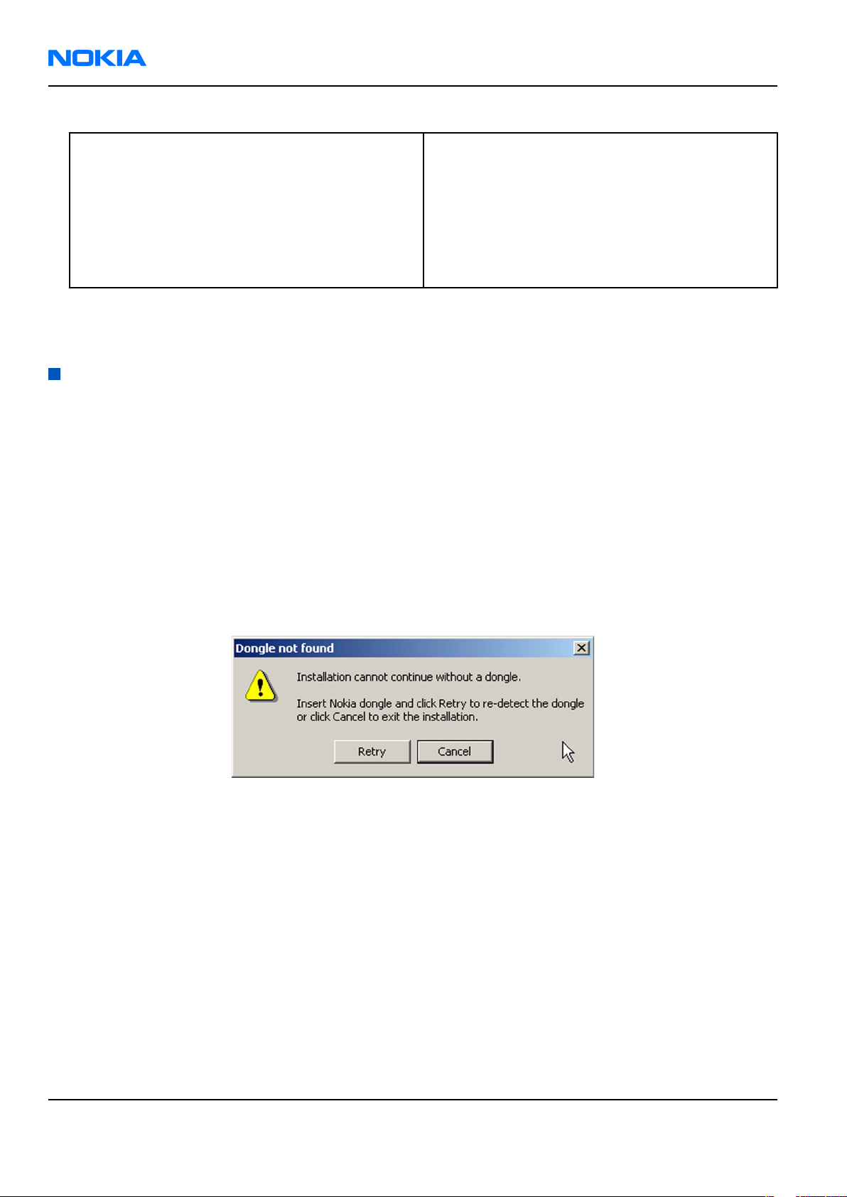
At some point during the installation procedure, you may get the following message:
Figure 2 Dongle not found
This may be a result of a defective or too old PKD-1 dongle.
Check the COM/parallel ports or USB ports used. After correcting the problem, you can restart the installation.
For more detailed information, please refer to
Tip: Each feature in
program. Press the F1 key or the feature’s Help button to activate a Help file.
Phoenix
has its own Help function, which can be activated while running the
Phoenix
Help files.
Steps
1. To start the installation, run the application file (for example,
2. In the
Page 2 –6 COMPANY CONFIDENTIAL Issue 1
Welcome
dialogue, click Next.
Copyright © 2007 Nokia. All rights reserved.
phoenix_service_sw_2004_39_x_xx.exe
).
Page 29
RM-135
Service Software Instructions Nokia Customer Care
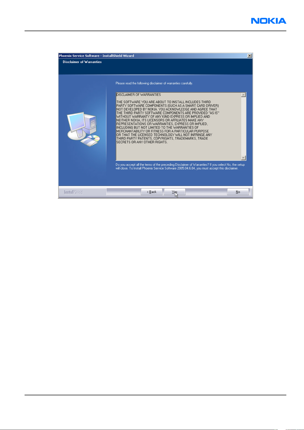
3. Read the disclaimer text carefully and click Yes.
Figure 3 Disclaimer text
4. Choose the destination folder.
The default folder
C:\ProgramFiles\Nokia\Phoenix
is recommended.
5. To continue, click Next.
To choose another location, click Browse (not recommended).
6. Wait for the components to be copied.
The progress of the installation is shown in the
Setup Status
window.
7. Wait for the drivers to be installed and updated.
The process may take several minutes to complete.
If the operating system does not require rebooting, the PC components are registered right away.
If the operating system requires restarting your computer, the Install Shield Wizard will notifies about it.
Select Yes... to reboot the PC immediately or No... to reboot the PC manually afterwards.
After the reboot, all components are registered.
Note:
Phoenix
does not work, if the components have not been registered.
Issue 1 COMPANY CONFIDENTIAL Page 2 –7
Copyright © 2007 Nokia. All rights reserved.
Page 30
RM-135
Nokia Customer Care Service Software Instructions
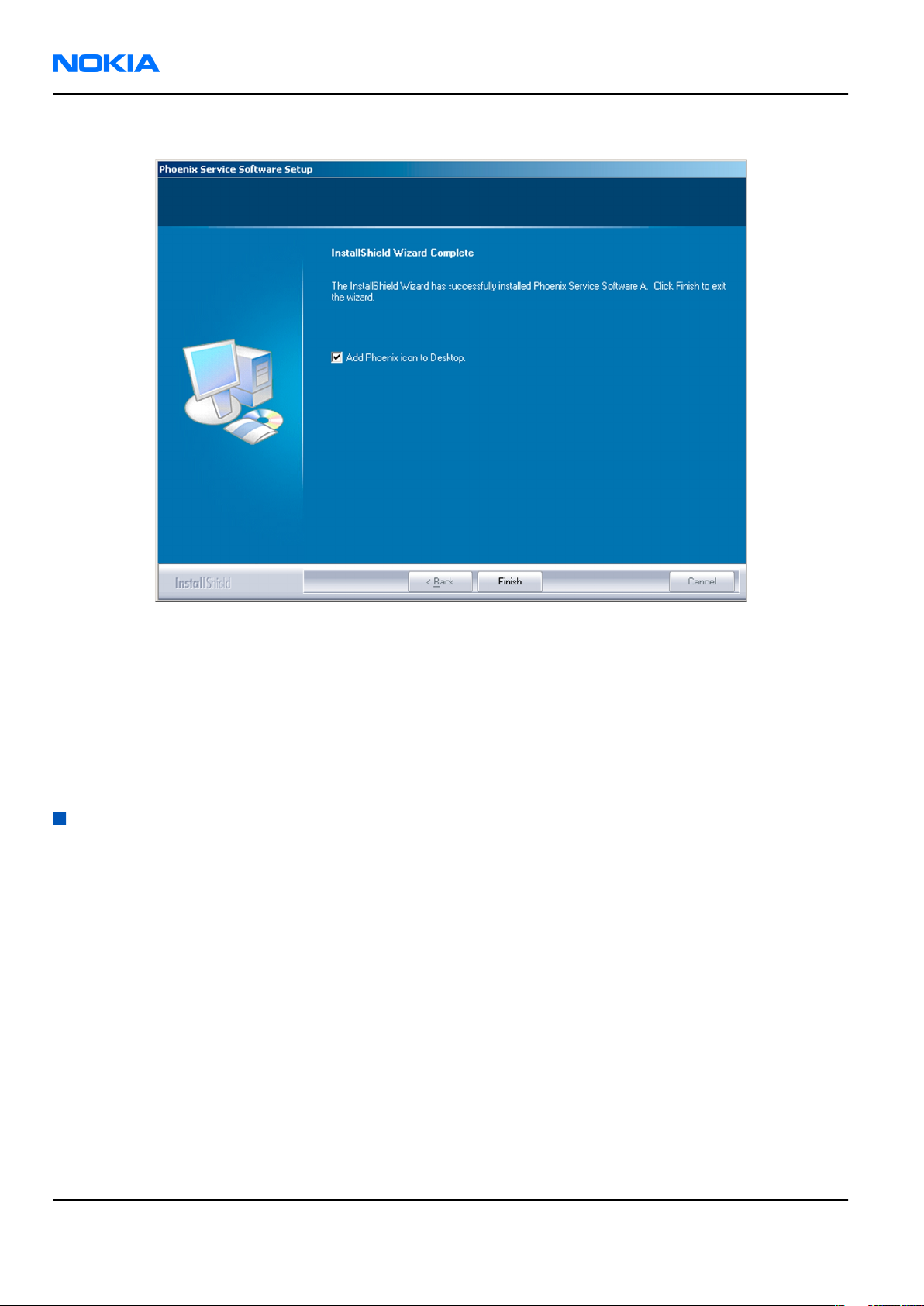
8. To end the installation, click Finish.
Figure 4 InstallShield Wizard Complete
Next actions
After the installation,
• installing phone model specific data package for
• configuring users and connections
FPS-10 flash prommer can be used after updating their flash update package files. FLS-5 flash prommer can
also be used.
Updating
Phoenix
Phoenix
can be used after:
Phoenix
installation
Context
• If you already have the
software when new versions are released.
• To update
• When you are updating, for example, from version a14_2004_16_4_47 to a15_2004_24_7_55, the update
will take place automatically without uninstallation.
• Always use the latest available versions of both
can be found in the phone model specific Technical Bulletins and phone data package
(shown during installation).
• If you try to update
a15_2004_24_7_55), you are asked if you want to uninstall the existing version. In this case you can choose
between a total uninstallation or a repair installation in a similar way when choosing to uninstall the
application from the
Phoenix
Phoenix
, you need to follow the same steps as when installing it for the first time.
service software installed on your computer, you need to update the
Phoenix
and the phone-specific data package. Instructions
readme.txt
Phoenix
Windows
with the same version you already have (for example, a15_2004_24_7_55 to
Control Panel.
files
Page 2 –8 COMPANY CONFIDENTIAL Issue 1
Copyright © 2007 Nokia. All rights reserved.
Page 31

RM-135
Service Software Instructions Nokia Customer Care
• If you try to install an older version (for example, downgrade from a15_2004_24_7_55 to
a14_2004_16_4_47), installation will be interrupted.
Figure 5 Installation interrupted
• Always follow the instructions on the screen.
Steps
1. Download the installation package to your computer hard disk.
2. Close all other programs.
3. Run the application file (for example,
phoenix_service_sw_2004_39_x_xx.exe
).
Results
A new
Phoenix
version is installed and driver versions are checked and updated.
Uninstalling
Phoenix
Context
You can uninstall
Phoenix
service software manually from the
Windows
Control Panel.
Steps
1. Open the Windows Control Panel, and choose Add/Remove Programs.
Issue 1 COMPANY CONFIDENTIAL Page 2 –9
Copyright © 2007 Nokia. All rights reserved.
Page 32

RM-135
Nokia Customer Care Service Software Instructions
2. To uninstall
Phoenix
, choose Phoenix Service Software→Change/Remove→Remove .
Figure 6 Remove program
The progress of the uninstallation is shown.
3. If the operating system does not require rebooting, click Finish to complete.
Figure 7 Finish uninstallation
Page 2 –10 COMPANY CONFIDENTIAL Issue 1
Copyright © 2007 Nokia. All rights reserved.
Page 33

RM-135
Service Software Instructions Nokia Customer Care
If the operating system requires rebooting, InstallShield Wizard will notify you. Select Yes... to reboot the
PC immediately and No... to reboot the PC manually afterwards.
Repairing
Phoenix
installation
Context
If you experience any problems with the service software or suspect that files have been lost, use the repair
function before completely reinstalling
Note: The original installation package (for example,
must be found on your PC when you run the repair setup.
Phoenix
.
phoenix_service_sw_a15_2004_24_7_55.exe
Steps
1. Open Windows Control Panel→Add/Remove Programs .
2. Choose Phoenix Service Software→Change/Remove .
3. In the following view, select Repair.
)
Figure 8 Repair program
Phoenix
The procedure is the same as when updating
4. To complete the repair, click Finish.
reinstalls components and registers them.
Phoenix
.
Phone data package overview
Each product has its own data package (DP). The product data package contains all product-specific data files
to make the Phoenix service software and tools usable with a certain phone model.
The phone data package contains the following:
• Product software binary files
Issue 1 COMPANY CONFIDENTIAL Page 2 –11
Copyright © 2007 Nokia. All rights reserved.
Page 34

RM-135
Nokia Customer Care Service Software Instructions
• Files for type label printing
• Validation file for the fault log repair data reporting system
• All product-specific configuration files for Phoenix software components
Data files are stored in C:\Program Files\Nokia\Phoenix (default).
Installing phone data package
Prerequisites
• A phone-specific data package contains all data required for the
to be used with a certain phone model.
• Check that a dongle is attached to the parallel port of your computer.
• Install
• Download the installation package (for example,
in C:\TEMP).
• Close all other programs.
(XX-XX = type designator of the product)
If you already have
released.
Phoenix
service software.
XX-XX_dp_EA_v_1_0.exe
Phoenix
Note: Often
version of
available versions of both. Instructions can be found in phone-specific Technical Bulletins and
readme.txt
Phoenix
Phoenix
files of data packages.
installed on your computer, you will need to update it when a new version is
and the phone-specific data package come in pairs, meaning that a certain
can only be used with a certain version of a data package. Always use the latest
Phoenix
service software and service tools
) to your computer (for example,
Steps
1. To start the installation, run the application file (for example,
Wait for the installation files to be extracted.
XX-XX_dp_EA_ v_1_0.exe
),
Page 2 –12 COMPANY CONFIDENTIAL Issue 1
Copyright © 2007 Nokia. All rights reserved.
Page 35

RM-135
Service Software Instructions Nokia Customer Care
2. Click Next.
3. In the following view you can see the contents of the data package. Read the text carefully. There is
information about the
Phoenix
version required with this data package.
Figure 9 Data package setup information
4. To continue, click Next.
Issue 1 COMPANY CONFIDENTIAL Page 2 –13
Copyright © 2007 Nokia. All rights reserved.
Page 36

RM-135
Nokia Customer Care Service Software Instructions
5. Choose the destination folder, and click Next to continue.
Figure 10 Data package destination folder
The InstallShield Wizard checks where
6. To start copying the files, click Next.
Phoenix
is installed, and the directory is shown.
Page 2 –14 COMPANY CONFIDENTIAL Issue 1
Copyright © 2007 Nokia. All rights reserved.
Page 37

RM-135
Service Software Instructions Nokia Customer Care
Phone model specific files are installed. Please wait.
7. To complete the installation, click Finish.
Figure 11 InstallShield Wizard Complete
Next actions
Phoenix
• Configuring users
• Managing connections
FPS-10 can be used after updating its flash update package files. FLS-5 flash prommer can also be used.
can be used for flashing phones and printing type labels after:
Uninstalling phone data package
Context
There is no need to uninstall an older version of a data package, unless instructions to do so are given in the
readme.txt
Please read all related documents carefully.
file of the data package and bulletins related to the release.
Steps
1. Locate the data package installation file (e.g.
2. To start the uninstallation procedure, double-click the data package installation file.
XX-XX_dp_EA_v_1_0.exe
) from your computer.
Issue 1 COMPANY CONFIDENTIAL Page 2 –15
Copyright © 2007 Nokia. All rights reserved.
Page 38

RM-135
Nokia Customer Care Service Software Instructions
3. To uninstall the data package, click OK or to interrupt the uninstallation, click Cancel.
Figure 12 Uninstalling phone data package
4. When the data package is uninstalled, click Finish.
Figure 13 Finishing data package uninstallation
Alternative steps
• You can also uninstall the data package manually from
Control Panel→Add/Remove Programs→xx-xx* Phone Data Package . (*= type designator of the
phone).
Page 2 –16 COMPANY CONFIDENTIAL Issue 1
Copyright © 2007 Nokia. All rights reserved.
Page 39

RM-135
Service Software Instructions Nokia Customer Care
Configuring users in
Phoenix
Steps
1. Start
2. To add a new user, or to edit existing ones, click Maintain.
3. To add a new user, click New.
4. Type in the name and initials of the user, and click OK.
5. Select the desired user from the
Phoenix
If the user ID is already configured, select s/he from the
The user is added to the user name list.
service software, and log in.
Figure 14 Phoenix login
User name
drop-down list, and click OK.
User name
drop-down list, and click OK.
Figure 15 New user configured
Managing connections in
Phoenix
Context
With the Manage Connections feature you can edit and delete existing connections or create new ones.
Note: After choosing the desired connection, and connecting the phone to a PC for the first time,
allow the PC to install the USB device drivers first. Please note that this may take some time to
complete.
If there are problems after the driver installation, check that the USB connection is active from the
Windows Control Panel. If the problem persists, contact the local PC support.
Steps
1. Start
2. Choose File→Manage Connections... .
Issue 1 COMPANY CONFIDENTIAL Page 2 –17
Phoenix
, and log in.
Copyright © 2007 Nokia. All rights reserved.
Page 40

RM-135
Nokia Customer Care Service Software Instructions
3. To add a new connection, click Add.
4. Select Manual mode, and click Next to continue.
If you want to create the connection using the Connection Wizard, connect the tools and a phone to your
PC. The wizard will automatically try to configure the correct connection.
Figure 16 Select mode: Manual
i For an FPS-10 flash prommer with a USB Connection, choose the following connection settings:
• Media: FPS-10 USB
• DEVICE_INDEX: 0
• SERIAL_NUM: See Serial No from the label attached to the bottom of FPS-10
• ACTIVE_MEDIA: USB
ii For an FPS-10 flash prommer with a LAN connection, choose the following connection settings:
• Media: FPS-10 TCP/IP
• NET_SERV_NAME: Click Scan.... Choose your own FPS-10 device based on the correct MAC address.
See Serial No from the label attached to the bottom of your FPS-10.
• PORT_NUM: Use the default value, and click Next.
• PROTOCOL_FAMILY: Use the default value, and click Next.
• SOCKET TYPE: Use the default value, and click Next.
• TX_BUFFER_SIZE: Use the default value, and click Next.
• RX_BUFFER_SIZE: Use the default value, and click Next.
iii For a plain USB connection, choose the following connection settings:
Note: First connect the DKE-2 cable between the PC USB port and phone.
• Media: USB
Page 2 –18 COMPANY CONFIDENTIAL Issue 1
Copyright © 2007 Nokia. All rights reserved.
Page 41

RM-135
Service Software Instructions Nokia Customer Care
iv For an FSL-5 flash prommer choose the following connection settings:
• Media: FBus
• PORT_NUM: xx
See the correct Port from the FLS Device Control Panel at the right hand side bottom corner in the
system tray. Click at the symbol of the FLS Device Control Panel, the UI opens and shows the
connected device with its serial and the used COM port.
5. To complete the configuration, click Finish.
Issue 1 COMPANY CONFIDENTIAL Page 2 –19
Copyright © 2007 Nokia. All rights reserved.
Page 42

RM-135
Nokia Customer Care Service Software Instructions
6. Click the connection you want to activate. Use the up/down arrows located on the right hand side to move
it on top of the list, then click Apply.
Figure 17 Connections list
The connection is activated, and it can be used after closing the
The connection information is shown at the right hand bottom corner of the screen.
Figure 18 Connection information
7. To use the connection, connect the phone to your PC with correct service tools. Make sure the phone is
switched on, and then choose File→Scan Product .
Manage Connection
window.
Results
The product support module information appears in the status bar:
Figure 19 Product support module information (example from RM-1)
Installing flash support files for FPS-10
Prerequisites
• Install
• Install phone model specific data package for
• If you want to update the flash support files, they are delivered in the same installation package with
Phoenix
In case you want to update the MCU files, install the latest data package (see Technical Bulletins for
information on the latest one).
Normally, it is enough to install
always includes the latest flash update package files for FPS-10.
• A separate installation package for flash support files is available. The files can be updated according to
these instructions, if updates appear between
Phoenix
or newer
service software.
Phoenix
packages beginning from beginning from April 2007.
Phoenix
Phoenix
and the phone-specific data package because the installation
Phoenix
.
data package releases.
Context
If you are not using a separate installation package, you can skip this section and continue with "Updating
FPS-10 flash prommer software" (page 2–23) after installing a new phone data package.
Page 2 –20 COMPANY CONFIDENTIAL Issue 1
Copyright © 2007 Nokia. All rights reserved.
Page 43

RM-135
Service Software Instructions Nokia Customer Care
Steps
1. To begin the installation, double-click the flash update file (for example,
flash_update_03_183_0014.exe
).
Figure 20 Flash update welcome dialog
If the same version of the flash update package already exists, and you want to reinstall it, the previous
package is first uninstalled.
Restart installation again after the uninstallation.
2. If you try to downgrade the existing version to older ones, the setup will be aborted. If there is a need to
downgrade the version, uninstall newer files manually from the Windows Control Panel, and then rerun
the installation.
Figure 21 Flash installation interrupted
If an older version exists on your PC and it needs to be updated, click Next to continue installation.
Issue 1 COMPANY CONFIDENTIAL Page 2 –21
Copyright © 2007 Nokia. All rights reserved.
Page 44

RM-135
Nokia Customer Care Service Software Instructions
3. It is recommended to install the files to the default destination folder
To continue, click Next.
C:\Program Files\Nokia\Phoenix
.
Figure 22 Flash destination folder
When installing the flash update files for the first time, you may choose another location by selecting
Browse (not recommended).
Page 2 –22 COMPANY CONFIDENTIAL Issue 1
Copyright © 2007 Nokia. All rights reserved.
Page 45

RM-135
Service Software Instructions Nokia Customer Care
4. To complete the installation procedure, click Finish .
Figure 23 Finish flash update
Next actions
FPS-10 flash prommer must be updated using
Updating FPS-10 flash prommer software
Phoenix
.
Steps
1. Start
2. Choose the correct connection for your flash prommer: File→Manage Connections...
3. Choose Flashing→Prommer maintenance .
4. To update the FPS-10 software, click Update, and select the appropriate file or
Phoenix
from
C:\Program Files\Nokia\Phoenix\Flash
service software, and log in.
fpsxupd.ini
.
(for FPS-10)
Figure 24 Flash directory window
Issue 1 COMPANY CONFIDENTIAL Page 2 –23
Copyright © 2007 Nokia. All rights reserved.
Page 46

RM-135
Nokia Customer Care Service Software Instructions
Tip: All files can be loaded separately to the prommer used. To do this, click the right mouse button
in the
Flash Box Files
pane and select the file type(s) to be loaded.
5. Click OK.
Figure 25 Prommer software update finished
6. To close the
Prommer Maintenance
window, click Close.
Figure 26
Prommer Maintenance
window
Dead phone USB flashing
Context
This procedure is performed when the phone did not start after interrupting flashing.
Required equipment and setup:
• Latest Phoenix software
• DKE-2 USB cable
Page 2 –24 COMPANY CONFIDENTIAL Issue 1
Copyright © 2007 Nokia. All rights reserved.
Page 47

RM-135
Service Software Instructions Nokia Customer Care
• Phone specific data package
• Phone which does not start after interrupted flash process
Steps
1. To prepare the flashing process, run Phoenix service software and log in.
2. Chose File→Manage Connections and activate No Connection. Use the up/down arrows located in the
right hand side to move it on top of the list, then click Apply.
After closing the Manage Connection window the no connection symbol is shown at the right hand bottom
corner of the screen.
3. Choose the product manually from File→Open product and click OK. Wait for the phone type designator
(e.g. RM-135) to be displayed in the status bar.
Issue 1 COMPANY CONFIDENTIAL Page 2 –25
Copyright © 2007 Nokia. All rights reserved.
Page 48

RM-135
Nokia Customer Care Service Software Instructions
4. Go to Flashing→Firmware Update and select the correct product code by clicking on the three spots
right hand next to the product code. All available product codes in the current data package are listed.
Activate the correct code and click OK.
The chosen product code is now shown with the software version according to the installed data package.
5. Select Dead Phone USB Flashing and connect the phone via USB cable.
6. Start the flashing process by clicking Start.
Flashing started and after a few seconds Phoenix wants to open a connection to the phone. Press the
power button of the phone if you are asked to. The flash process continues. Otherwise, flashing failed and
the procedure has to be repeated.
Page 2 –26 COMPANY CONFIDENTIAL Issue 1
Copyright © 2007 Nokia. All rights reserved.
Page 49

RM-135
Service Software Instructions Nokia Customer Care
After pressing the power button:
Issue 1 COMPANY CONFIDENTIAL Page 2 –27
Copyright © 2007 Nokia. All rights reserved.
Page 50

RM-135
Nokia Customer Care Service Software Instructions
Progress messages on the screen show actions during phone programming, please wait.
Programming is completed when Flashing Completed message is displayed.
Page 2 –28 COMPANY CONFIDENTIAL Issue 1
Copyright © 2007 Nokia. All rights reserved.
Page 51

Nokia Customer Care
3 — Service Tools and Service
Concepts
Issue 1 COMPANY CONFIDENTIAL Page 3 –1
Copyright © 2007 Nokia. All rights reserved.
Page 52

RM-135
Nokia Customer Care Service Tools and Service Concepts
(This page left intentionally blank.)
Page 3 –2 COMPANY CONFIDENTIAL Issue 1
Copyright © 2007 Nokia. All rights reserved.
Page 53

RM-135
Service Tools and Service Concepts Nokia Customer Care
Table of Contents
Service tools............................................................................................................................................................3–5
Product specific tools........................................................................................................................................3–5
FS-23..............................................................................................................................................................3–5
MJ-93..............................................................................................................................................................3–6
RJ-111 ............................................................................................................................................................3–7
SA-102 ...........................................................................................................................................................3–8
SS-112............................................................................................................................................................3–8
General tools......................................................................................................................................................3–8
CU-4................................................................................................................................................................3–9
FLS-5 ........................................................................................................................................................... 3–10
FPS-10......................................................................................................................................................... 3–10
PK-1............................................................................................................................................................. 3–10
PKD-1 .......................................................................................................................................................... 3–10
RJ-104 ......................................................................................................................................................... 3–11
RJ-157 ......................................................................................................................................................... 3–11
RJ-160 ......................................................................................................................................................... 3–11
RJ-169 ......................................................................................................................................................... 3–11
RJ-93 ........................................................................................................................................................... 3–12
SB-6............................................................................................................................................................. 3–12
SPS-1........................................................................................................................................................... 3–12
SRT-6........................................................................................................................................................... 3–12
SS-46........................................................................................................................................................... 3–12
SS-62........................................................................................................................................................... 3–13
SS-93........................................................................................................................................................... 3–13
ST-37........................................................................................................................................................... 3–13
ST-40........................................................................................................................................................... 3–13
ST-55........................................................................................................................................................... 3–13
SX-4............................................................................................................................................................. 3–14
Cables............................................................................................................................................................... 3–14
CA-31D ........................................................................................................................................................ 3–14
CA-35S......................................................................................................................................................... 3–14
CA-58RS....................................................................................................................................................... 3–15
DAU-9S........................................................................................................................................................ 3–15
DKE-2........................................................................................................................................................... 3–15
PCS-1........................................................................................................................................................... 3–15
XCS-4........................................................................................................................................................... 3–16
XRF-1........................................................................................................................................................... 3–16
XRS-6........................................................................................................................................................... 3–16
Service tools spare parts................................................................................................................................ 3–16
Coax cable assy for MJ-93 ......................................................................................................................... 3–16
Spare UI flex unit for MJ-93 ...................................................................................................................... 3–17
Service concepts .................................................................................................................................................. 3–17
POS (Point of Sale) flash concept .................................................................................................................. 3–17
Flash concept with FPS-10............................................................................................................................. 3–18
Flash concept with FLS-5 and SS-46 ............................................................................................................. 3–19
CU-4 flash concept with FPS-10..................................................................................................................... 3–20
Flash concept with FLS-5 and SS-62 ............................................................................................................. 3–21
Flash concept with FLS-5 and module jig .................................................................................................... 3–22
Module jig service concept............................................................................................................................ 3–23
Service concept for RF testing and RF/BB tuning........................................................................................ 3–24
Issue 1 COMPANY CONFIDENTIAL Page 3 –3
Copyright © 2007 Nokia. All rights reserved.
Page 54

RM-135
Nokia Customer Care Service Tools and Service Concepts
RF testing / BB tuning concept...................................................................................................................... 3–25
RF/BB tuning and flashing with FPS-10 ....................................................................................................... 3–26
RF/BB tuning and flashing with FLS-5.......................................................................................................... 3–27
Bluetooth test concept with SB-6................................................................................................................. 3–28
Connecting to flash adapter............................................................................................................................... 3–29
List of Tables
Table 1 MJ-93 attenuation table ...........................................................................................................................3–6
Table 2 SA-102 attenuation table.........................................................................................................................3–8
List of Figures
Figure 27 POS flash concept ............................................................................................................................... 3–17
Figure 28 Basic flash concept with FPS-10........................................................................................................ 3–18
Figure 29 Flash concept with FLS-5 and SS-46 ................................................................................................. 3–19
Figure 30 CU-4 flash concept with FPS-10......................................................................................................... 3–20
Figure 31 Basic flash concept with FLS-5 and SS-62 ........................................................................................ 3–21
Figure 32 Flash concept with FLS-5 and module jig ........................................................................................ 3–22
Figure 33 Module jig service concept................................................................................................................ 3–23
Figure 34 Service concept for RF testing and RF/BB tuning............................................................................ 3–24
Figure 35 RF testing / BB tuning concept ......................................................................................................... 3–25
Figure 36 RF/BB tuning and flashing with FPS-10 ........................................................................................... 3–26
Figure 37 RF/BB tuning and flashing with FLS-5.............................................................................................. 3–27
Figure 38 Bluetooth test concept with SB-6..................................................................................................... 3–28
Page 3 –4 COMPANY CONFIDENTIAL Issue 1
Copyright © 2007 Nokia. All rights reserved.
Page 55

RM-135
Service Tools and Service Concepts Nokia Customer Care
Service tools
Product specific tools
The table below gives a short overview of service tools that can be used for testing, error analysis and repair
of product RM-135, refer to various concepts.
FS-23 Flash adapter FS-23 is a product specific adapter for SW update and testing purposes.
It is compatible to SS-62 and SS-46. It provides galvanic connetion to
terminal test pads and battery connector.
Issue 1 COMPANY CONFIDENTIAL Page 3 –5
Copyright © 2007 Nokia. All rights reserved.
Page 56

RM-135
Nokia Customer Care Service Tools and Service Concepts
MJ-93 Module jig The module jig offers engine module component level repair, analysis
and alignment capabilities in combination with CU-4.
Features:
• connection interfaces for GSM, WCDMA and Bluetooth antenna
• galvanic connection to engine module test pads
• multiplexing between USB an FBUS media, controlled by VUSB with
CU-4
• lid interconnection with test points for measurements
• connection to lid assembly incl. displays and earpiece
• connector for e.g. CU-4 control unit
• connection for BT / SIM / SD-card module
Note: Lid assembly incl. displays is not designed to be used
for repair and analysis. The connection cycles for lid are
limited to 10 times.
•
Band Channel Frequency /
Table 1 MJ-93 attenuation table
Loss / dB
MHz
GSM850 189 836.6 0.20
GSM850 189 881.6 0.20
GSM900 37 897.4 0.20
GSM900 37 942.4 0.20
GSM1800 700 1747.8 0.20
GSM1800 700 1842.8 0.20
GSM1900 661 1880 0.20
WCDMA1 9750 1950 0.20
GSM1900 661 1960 0.20
WCDMA1 10700 2140 0.20
Page 3 –6 COMPANY CONFIDENTIAL Issue 1
Copyright © 2007 Nokia. All rights reserved.
Page 57

RM-135
Service Tools and Service Concepts Nokia Customer Care
RJ-111 Soldering jig RJ-111 is a jig to support component level exchange with soldering
machines for the engine module.
Issue 1 COMPANY CONFIDENTIAL Page 3 –7
Copyright © 2007 Nokia. All rights reserved.
Page 58

RM-135
Nokia Customer Care Service Tools and Service Concepts
SA-102 RF coupler SA-102 is an RF coupler for WCDMA and GSM RF testing. It is used
together with the product-specific flash adapter.
The following table shows attenuations from the antenna pads of the
mobile terminal to the SMA connector of SA-102 (+ / - 2dB ):
•
Band
Table 2 SA-102 attenuation table
Channel
UP/
DOWN
TX f
[MHz]TXLoss
[dB]
RX f
[MHz]RXLoss
(dB)
Low 128 824.2 12.0 869.2 10.0
GSM850
EGSM900
GSM1800
GSM1900
WCDMA I
Mid 189 836.4 11.3 881.4 9.5
High 251 848.8 10.5 893.8 9.0
Low1 975 880.2 9.5 925.2 10.7
Low2 1 890.2 9.3 935.2 11.0
Mid 37 897.4 9.0 942.4 11.2
High 124 915.8 9.5 960.8 12.0
Low 512 1710.2 7.6 1805.2 6.7
Mid 698 1747.4 7.3 1842.4 6.4
High 885 1784.8 7.0 1879.8 6.5
Low 512 1850.2 6.3 1930.2 7.5
Mid 661 1880.0 6.6 1960.0 8.0
High 810 1909.8 7.0 1989.8 8.6
9613 /
Low
10563 1922.4 7.3 2112.4 15.8
9750 /
Mid
10700 1950.0 7.9 2140.0 18.0
9887 /
High
10837 1977.6 8.3 2167.6 20.0
Note: It is recommended to add a 3dB attenuator directly at
coupler SMA connector.
SS-112 Camera recess 00 bit ¼” bit for the Torque screwdriver to be added as part of the service
box.
General tools
The table below gives a short overview of service tools that can be used for testing, error analysis and repair
of product RM-135, refer to various concepts.
Page 3 –8 COMPANY CONFIDENTIAL Issue 1
Copyright © 2007 Nokia. All rights reserved.
Page 59

RM-135
Service Tools and Service Concepts Nokia Customer Care
CU-4 Control unit CU-4 is a general service tool used with a module jig and/or a flash
adapter. It requires an external 12 V power supply.
The unit has the following features:
• software controlled via USB
• EM calibration function
• Forwards FBUS/Flashbus traffic to/from terminal
• Forwards USB traffic to/from terminal
• software controlled BSI values
• regulated VBATT voltage
• 2 x USB2.0 connector (Hub)
• FBUS and USB connections supported
When using CU-4, note the special order of connecting cables and
other service equipment:
Instructions
1 Connect a service tool (jig, flash adapter) to CU-4.
2 Connect CU-4 to your PC with a USB cable.
3 Connect supply voltage (12 V)
4 Connect an FBUS cable (if necessary).
5 Start Phoenix service software.
Note: Phoenix enables CU-4 regulators via USB when it is
started.
Reconnecting the power supply requires a Phoenix restart.
Issue 1 COMPANY CONFIDENTIAL Page 3 –9
Copyright © 2007 Nokia. All rights reserved.
Page 60

RM-135
Nokia Customer Care Service Tools and Service Concepts
FLS-5 Flash device FLS-5 is a dongle and flash device incorporated into one package,
developed specifically for POS use.
FPS-10 Flash prommer FPS-10 interfaces with:
• PC
• Control unit
• Flash adapter
• Smart card
FPS-10 flash prommer features:
• Flash functionality for BB5 and DCT-4 terminals
• Smart Card reader for SX-2 or SX-4
• USB traffic forwarding
• USB to FBUS/Flashbus conversion
• LAN to FBUS/Flashbus and USB conversion
• Vusb output switchable by PC command
FPS-10 sales package includes:
• FPS-10 prommer
• Power Supply with 5 country specific cords
• USB cable
PK-1 Software protection
key
PK-1 is a hardware protection key with a USB interface. It has the same
functionality as the PKD-1 series dongle.
PK-1 is meant for use with a PC that does not have a series interface.
To use this USB dongle for security service functions please register
the dongle in the same way as the PKD-1 series dongle.
PKD-1 SW security device
SW security device is a piece of hardware enabling the use of the
service software when connected to the parallel (LPT) port of the PC.
Without the device, it is not possible to use the service software.
Printer or any such device can be connected to the PC through the
device if needed.
Page 3 –10 COMPANY CONFIDENTIAL Issue 1
Copyright © 2007 Nokia. All rights reserved.
Page 61

RM-135
Service Tools and Service Concepts Nokia Customer Care
RJ-104 Rework jig RJ-104 is a rework jig used when servicing the BTHFM (D6000) module.
It is used together with rework stencil ST-37.
RJ-157 Rework jig RJ-157 is a jig used for soldering and as a rework jig for the engine
module. It is used together with the ST-55 stencil.
RJ-160 Rework jig RJ-160 is a jig used for soldering and as a rework jig for the engine
module. It is used together with the ST-55 stencil.
RJ-169 Rework jig RJ-169 is a jig used for soldering and as a rework jig for the engine
module. It is used together with the ST-59 stencil.
Issue 1 COMPANY CONFIDENTIAL Page 3 –11
Copyright © 2007 Nokia. All rights reserved.
Page 62

RM-135
Nokia Customer Care Service Tools and Service Concepts
RJ-93 Rework jig RJ-93 is used as a rework jig for the Front End Module (FEM).
This rework jig takes the FEM or power amplifier (PA) module (N7520)
for spreading the soldering paste to the component. Must be used
together with the ST-40 stencil.
SB-6 Bluetooth test and
interface box (sales
package)
The SB-6 test box is a generic service device used to perform Bluetooth
bit error rate (BER) testing, and establishing cordless FBUS connection
via Bluetooth. An ACP-8x charger is needed for BER testing and an
AXS-4 cable in case of cordless interface usage testing .
Sales package includes:
• SB-6 test box
• Installation and warranty information
SPS-1 Soldering Paste
Spreader
SRT-6 Opening tool SRT-6 is used to open phone covers and B-to-B connectors.
SS-46 Interface adapter SS-46 acts as an interface adapter between the flash adapter and
FPS-10.
Page 3 –12 COMPANY CONFIDENTIAL Issue 1
Copyright © 2007 Nokia. All rights reserved.
Page 63

RM-135
Service Tools and Service Concepts Nokia Customer Care
SS-62 Generic flash adapter
base for BB5
• generic base for flash adapters and couplers
• SS-62 equipped with a clip interlock system
• provides standardised interface towards Control Unit
• provides RF connection using galvanic connector or coupler
• multiplexing between USB and FBUS media, controlled by VUSB
SS-93 Opening tool SS-93 is used for opening JAE connectors.
ST-37 BTHFM rework stencil ST-37 stencil is used with the RJ-104 rework jig to service the BTHFM
(D6000) module.
ST-40 Rework stencil ST-40 is a rework stencil that is used with the RJ-93 rework jig to
service the Front End Module (N7520).
ST-55 Rework stencil ST-55 is a rework stencil used with rework jig RJ-157 and RJ-160.
Issue 1 COMPANY CONFIDENTIAL Page 3 –13
Copyright © 2007 Nokia. All rights reserved.
Page 64

RM-135
Nokia Customer Care Service Tools and Service Concepts
SX-4 Smart card SX-4 is a BB5 security device used to protect critical features in tuning
and testing.
SX-4 is also needed together with FPS-10 when DCT-4 phones are
flashed.
Cables
The table below gives a short overview of service tools that can be used for testing, error analysis and repair
of product RM-135, refer to various concepts.
CA-31D USB cable The CA-31D USB cable is used to connect FPS-10 or FPS-11 to a PC. It is
included in the FPS-10 and FPS-11 sales packages.
CA-35S Power cable CA-35S is a power cable for connecting, for example, the FPS-10 flash
prommer to the Point-Of-Sales (POS) flash adapter.
Page 3 –14 COMPANY CONFIDENTIAL Issue 1
Copyright © 2007 Nokia. All rights reserved.
Page 65

RM-135
Service Tools and Service Concepts Nokia Customer Care
CA-58RS RF tuning cable RF tuning cable for use with a flash adapter.
CA-58RS RF cable extends adapter features to allow RF function tests
and RF tuning in GSM bands.
Features include:
• easy to use together with flash adapter or even stand alone
• most accurate RF connection to phone module under test
• most accurate RF connection to phone module under test
• low attenuation and small “ripple” over the width of each GSM band
Note: The RF cable must be used for RF tuning.
DAU-9S MBUS cable The MBUS cable DAU-9S has a modular connector and is used, for
example, between the PC's serial port and module jigs, flash adapters
or docking station adapters.
Note: Docking station adapters valid for DCT4 products.
DKE-2 Mini-USB cable USB to mini-USB connector cable.
PCS-1 Power cable The PCS-1 power cable (DC) is used with a docking station, a module
jig or a control unit to supply a controlled operating voltage.
Issue 1 COMPANY CONFIDENTIAL Page 3 –15
Copyright © 2007 Nokia. All rights reserved.
Page 66

RM-135
Nokia Customer Care Service Tools and Service Concepts
XCS-4 Modular cable XCS-4 is a shielded (one specially shielded conductor) modular cable
for flashing and service purposes.
XRF-1 RF cable The RF cable is used to connect, for example, a module repair jig to
the RF measurement equipment.
SMA to N-Connector ca. 610mm.
Attenuation for:
• GSM850/900: 0.3+-0.1 dB
• GSM1800/1900: 0.5+-0.1 dB
• WLAN: 0.6+-0.1dB
XRS-6 RF cable The RF cable is used to connect, for example, a module repair jig to
the RF measurement equipment.
SMA to N-Connector approximately 610 mm.
Attenuation for:
• GSM850/900: 0.3+-0.1 dB
• GSM1800/1900: 0.5+-0.1 dB
• WLAN: 0.6+-0.1dB
Service tools spare parts
The table below gives a short overview of service tools that can be used for testing, error analysis and repair
of product RM-135, refer to various concepts.
Coax cable assy for MJ-93
Spare part for MJ-93.
Page 3 –16 COMPANY CONFIDENTIAL Issue 1
Copyright © 2007 Nokia. All rights reserved.
Page 67

RM-135
Service Tools and Service Concepts Nokia Customer Care
Spare UI flex unit for MJ-93
Spare part for MJ-93.
Service concepts
POS (Point of Sale) flash concept
Figure 27 POS flash concept
Type Description
Product specific tools
BL-4B Battery
Other tools
FLS-5 POS flash dongle
PC with Phoenix service software
Cables
DKE-2 USB connectivity cable
Issue 1 COMPANY CONFIDENTIAL Page 3 –17
Copyright © 2007 Nokia. All rights reserved.
Page 68

RM-135
Nokia Customer Care Service Tools and Service Concepts
Flash concept with FPS-10
Figure 28 Basic flash concept with FPS-10
Type Description
Product specific tools
FS-23 Flash adapter
Other tools
FPS-10 Flash prommer box
PKD-1/PK-1 SW security device
SS-46 Interface adapter
PC with Phoenix service software
Cables
XCS-4 Modular cable
CA-35S Power cable
USB cable
Page 3 –18 COMPANY CONFIDENTIAL Issue 1
Copyright © 2007 Nokia. All rights reserved.
Page 69

RM-135
Service Tools and Service Concepts Nokia Customer Care
Flash concept with FLS-5 and SS-46
Figure 29 Flash concept with FLS-5 and SS-46
Type Description
Product specific tools
FS-23 Flash adapter
Other tools
ACF-8 Universal power supply (not shown in the concept picture)
FLS-5 POS flash dongle
SS-46 Interface adapter
PC with Phoenix service software
Cables
CA-89DS Cable
Issue 1 COMPANY CONFIDENTIAL Page 3 –19
Copyright © 2007 Nokia. All rights reserved.
Page 70

RM-135
Nokia Customer Care Service Tools and Service Concepts
CU-4 flash concept with FPS-10
Figure 30 CU-4 flash concept with FPS-10
Type Description
Product specific tools
FS-23 Flash adapter
Other tools
CU-4 Control unit
FPS-10 Flash prommer box
PKD-1/PK-1 SW security device
SS-62 Flash adapter base
SX-4 Smart card
PC with Phoenix service software
Cables
PCS-1 Power cable
XCS-4 Modular cable
Standard USB cable
USB cable
Page 3 –20 COMPANY CONFIDENTIAL Issue 1
Copyright © 2007 Nokia. All rights reserved.
Page 71

RM-135
Service Tools and Service Concepts Nokia Customer Care
Flash concept with FLS-5 and SS-62
Figure 31 Basic flash concept with FLS-5 and SS-62
Type Description
Product specific tools
FS-23 Flash adapter
Other tools
CU-4 Control unit
FLS-5 POS flash dongle
SS-62 Flash adapter base
PC with Phoenix service software
Cables
CA-89DS Cable
PCS-1 Power cable
Standard USB cable
USB cable
Issue 1 COMPANY CONFIDENTIAL Page 3 –21
Copyright © 2007 Nokia. All rights reserved.
Page 72

RM-135
Nokia Customer Care Service Tools and Service Concepts
Flash concept with FLS-5 and module jig
Figure 32 Flash concept with FLS-5 and module jig
Type Description
Product specific tools
MJ-93 Module jig
Other tools
CU-4 Control unit
FLS-5 POS flash dongle
PC with Phoenix service software
Cables
CA-89DS Cable
PCS-1 DC power cable
USB cable
Page 3 –22 COMPANY CONFIDENTIAL Issue 1
Copyright © 2007 Nokia. All rights reserved.
Page 73

RM-135
Service Tools and Service Concepts Nokia Customer Care
Module jig service concept
Figure 33 Module jig service concept
Type Description
Phone specific tools
MJ-93 Module jig
Other tools
CU-4 Control unit
FPS-10 Flash prommer box
PKD-1/PK-1 SW security device
SX-4 Smart card
PC with Phoenix service software
Measurement equipment
Cables
PCS-1 DC power cable
XCS-4 Modular cable
XRS-6 RF cable
USB cable
Issue 1 COMPANY CONFIDENTIAL Page 3 –23
Copyright © 2007 Nokia. All rights reserved.
Page 74

RM-135
Nokia Customer Care Service Tools and Service Concepts
Type Description
GPIB control cable
Service concept for RF testing and RF/BB tuning
Figure 34 Service concept for RF testing and RF/BB tuning
Type Description
Product specific tools
MJ-93 Module jig
Other tools
CU-4 Control unit
PKD-1/PK-1 SW security device
SX-4 Smart card
Measurement equipment
Smart card reader
PC with Phoenix service software
Cables
DAU-9s MBUS cable
PCS-1 DC power cable
Page 3 –24 COMPANY CONFIDENTIAL Issue 1
Copyright © 2007 Nokia. All rights reserved.
Page 75

RM-135
Service Tools and Service Concepts Nokia Customer Care
Type Description
XRS-6 RF cable
GPIB control cable
USB cable
RF testing / BB tuning concept
Figure 35 RF testing / BB tuning concept
Type Description
Product specific tools
FS-23 Flash adapter
SA-102 RF coupler
Other tools
CU-4 Control unit
PKD-1/PK-1 SW security device
SS-62 Flash adapter base
SX-4 Smart card
Measurement equipment
Smart card reader
PC with Phoenix service software
Issue 1 COMPANY CONFIDENTIAL Page 3 –25
Copyright © 2007 Nokia. All rights reserved.
Page 76

RM-135
Nokia Customer Care Service Tools and Service Concepts
Type Description
Cables
DAU-9s MBUS cable
PCS-1 DC power cable
XRS-6 RF cable
USB cable
RF/BB tuning and flashing with FPS-10
Figure 36 RF/BB tuning and flashing with FPS-10
Type Description
Product specific tools
MJ-93 Module jig
Other tools
CU-4 Control unit
FPS-10 Flash prommer box
PKD-1/PK-1 SW security device
SX-4 Smart card
Measurement equipment
PC with Phoenix service software
Page 3 –26 COMPANY CONFIDENTIAL Issue 1
Copyright © 2007 Nokia. All rights reserved.
Page 77

RM-135
Service Tools and Service Concepts Nokia Customer Care
Type Description
Cables
PCS-1 DC power cable
XCS-4 Modular cable
XRS-6 RF cable
USB cable
RF/BB tuning and flashing with FLS-5
Figure 37 RF/BB tuning and flashing with FLS-5
Type Description
Product specific tools
MJ-93 Module jig
Other tools
CU-4 Control unit
FLS-5 POS flash dongle
PKD-1/PK-1 SW security device
SX-4 Smart card
Measurement equipment
PC with Phoenix service software
Issue 1 COMPANY CONFIDENTIAL Page 3 –27
Copyright © 2007 Nokia. All rights reserved.
Page 78

RM-135
Nokia Customer Care Service Tools and Service Concepts
Type Description
Smart card reader
Cables
CA-89DS Cable
PCS-1 DC power cable
XRS-6 RF cable
USB cable
Bluetooth test concept with SB-6
Figure 38 Bluetooth test concept with SB-6
Type Description
Product specific tools
FS-23 Flash adapter
Other tools
CU-4 Control unit
PKD-1 SW Security device
SS-62 Generic base adapter
SB-6 BT test box
ACP-8 Charger for SB-6
Cables
PCS-1 Power cable
DAU-9S Cable
Page 3 –28 COMPANY CONFIDENTIAL Issue 1
Copyright © 2007 Nokia. All rights reserved.
Page 79

RM-135
Service Tools and Service Concepts Nokia Customer Care
Type Description
PCS-1 DC power cable
Standard USB cable
Connecting to flash adapter
Prerequisites
The picture shows the “close” position.
Before connecting the phone to the FS-23 flash adapter, make sure that the locking mechanism is open like
shown in the picture.
Issue 1 COMPANY CONFIDENTIAL Page 3 –29
Copyright © 2007 Nokia. All rights reserved.
Page 80

RM-135
Nokia Customer Care Service Tools and Service Concepts
Steps
1. Start the assembly straight from the top.
2. Press at top of the phone and hold it into position.
Page 3 –30 COMPANY CONFIDENTIAL Issue 1
Copyright © 2007 Nokia. All rights reserved.
Page 81

RM-135
Service Tools and Service Concepts Nokia Customer Care
3. Close the locking mechanism while pressing the lever.
The phone is now fixed on the FS-23 flash adapter.
4. To remove the phone, pull the lever to unlock the mechanism.
Issue 1 COMPANY CONFIDENTIAL Page 3 –31
Copyright © 2007 Nokia. All rights reserved.
Page 82

RM-135
Nokia Customer Care Service Tools and Service Concepts
5. Lift up the phone from the opposite side of the phone´s battery connector.
Page 3 –32 COMPANY CONFIDENTIAL Issue 1
Copyright © 2007 Nokia. All rights reserved.
Page 83

Nokia Customer Care
4 — BB Troubleshooting and
Manual Tuning Guide
Issue 1 COMPANY CONFIDENTIAL Page 4 –1
Copyright © 2007 Nokia. All rights reserved.
Page 84

RM-135
Nokia Customer Care BB Troubleshooting and Manual Tuning Guide
(This page left intentionally blank.)
Page 4 –2 COMPANY CONFIDENTIAL Issue 1
Copyright © 2007 Nokia. All rights reserved.
Page 85

RM-135
BB Troubleshooting and Manual Tuning Guide Nokia Customer Care
Table of Contents
Troubleshooting overview ....................................................................................................................................4–5
Dead or jammed device troubleshooting............................................................................................................4–6
General power checking ........................................................................................................................................4–7
Clocking troubleshooting ......................................................................................................................................4–8
Charging troubleshooting .....................................................................................................................................4–9
Backup battery troubleshooting........................................................................................................................ 4–10
Flash programming fault troubleshooting....................................................................................................... 4–11
Combo memory troubleshooting ...................................................................................................................... 4–13
MicroSD card troubleshooting............................................................................................................................ 4–14
USB interface troubleshooting........................................................................................................................... 4–16
SIM card troubleshooting ................................................................................................................................... 4–18
MR sensor troubleshooting ................................................................................................................................ 4–20
Keyboard troubleshooting ................................................................................................................................. 4–21
Power key troubleshooting................................................................................................................................ 4–23
Vibra troubleshooting......................................................................................................................................... 4–24
Display module troubleshooting ....................................................................................................................... 4–25
General instructions for display troubleshooting....................................................................................... 4–25
Display troubleshooting ................................................................................................................................ 4–26
Backlights troubleshooting........................................................................................................................... 4–27
EL foil backlight troubleshooting ................................................................................................................. 4–29
LED driver troubleshooting ........................................................................................................................... 4–30
Power LED troubleshooting .......................................................................................................................... 4–32
Bluetooth and FM radio ...................................................................................................................................... 4–34
Introduction to Bluetooth/FM Radio troubleshooting ............................................................................... 4–34
Bluetooth settings for Phoenix..................................................................................................................... 4–35
Bluetooth self tests in Phoenix..................................................................................................................... 4–36
Bluetooth troubleshooting ........................................................................................................................... 4–38
FM radio troubleshooting.............................................................................................................................. 4–38
Audio troubleshooting........................................................................................................................................ 4–40
Audio troubleshooting test instructions...................................................................................................... 4–40
Internal earpiece troubleshooting ............................................................................................................... 4–44
Internal microphone troubleshooting......................................................................................................... 4–45
IHF speakers troubleshooting....................................................................................................................... 4–46
External headset microphone troubleshooting.......................................................................................... 4–47
External headset earpiece troubleshooting ................................................................................................ 4–48
Acoustics troubleshooting............................................................................................................................. 4–49
Introduction to acoustics troubleshooting ............................................................................................ 4–49
Earpiece troubleshooting......................................................................................................................... 4–50
IHF troubleshooting.................................................................................................................................. 4–51
Microphone troubleshooting ................................................................................................................... 4–52
Baseband manual tuning guide......................................................................................................................... 4–53
Certificate restoring for BB5 products.......................................................................................................... 4–53
Energy management calibration.................................................................................................................. 4–58
List of Tables
Table 3 Display module troubleshooting cases................................................................................................ 4–25
Table 4 Pixel defects ........................................................................................................................................... 4–25
Table 5 Calibration value limits ......................................................................................................................... 4–58
Issue 1 COMPANY CONFIDENTIAL Page 4 –3
Copyright © 2007 Nokia. All rights reserved.
Page 86

RM-135
Nokia Customer Care BB Troubleshooting and Manual Tuning Guide
List of Figures
Figure 39 Charging backup battery ................................................................................................................... 4–10
Figure 40 Discharging backup battery .............................................................................................................. 4–10
Figure 41 Take single trig measurement for the rise of the BSI signal. ........................................................ 4–12
Figure 42 USB connector..................................................................................................................................... 4–17
Figure 43 Bluetooth antenna............................................................................................................................. 4–34
Figure 44 Bluetooth and FM radio component layout..................................................................................... 4–35
Figure 45 BER test result..................................................................................................................................... 4–36
Figure 46 Bluetooth self tests in Phoenix......................................................................................................... 4–37
Figure 47 Single-ended output waveform of the Ext_in_HP_out measurement when earpiece is
connected. ................................................................................................................................................. 4–41
Figure 48 Differential output waveform of the Ext_in_IHF_out out loop measurement when speaker is
connected. ................................................................................................................................................. 4–42
Figure 49 Single-ended output waveform of the Ext_in_Ext_out loop........................................................... 4–42
Figure 50 Single-ended output waveform of the HP_in_Ext_out loop. .......................................................... 4–43
Page 4 –4 COMPANY CONFIDENTIAL Issue 1
Copyright © 2007 Nokia. All rights reserved.
Page 87

RM-135
BB Troubleshooting and Manual Tuning Guide Nokia Customer Care
Troubleshooting overview
For practical reasons, troubleshooting is divided into two sections;
• Baseband troubleshooting, including camera, FM radio and Bluetooth.
• RF troubleshooting
Issue 1 COMPANY CONFIDENTIAL Page 4 –5
Copyright © 2007 Nokia. All rights reserved.
Page 88

RM-135
Nokia Customer Care BB Troubleshooting and Manual Tuning Guide
Dead or jammed device troubleshooting
Troubleshooting flow
Page 4 –6 COMPANY CONFIDENTIAL Issue 1
Copyright © 2007 Nokia. All rights reserved.
Page 89

RM-135
BB Troubleshooting and Manual Tuning Guide Nokia Customer Care
General power checking
Check the following voltages:
Signal
name
VIO External
VBACK AVILMA ON ON 2.6 Back-up battery
VSIM1
VSIM2 AVILMA ON ON VBAT3
VDRAM External
VAUX AVILMA OFF OFF 2.78 FM radio, ALS, MR
VANA AVILMA ON ON 2.5 AVILMA VBAT4
VR1 AVILMA OFF ON 2.5 Crystal oscillators VBAT4
VRFC AVILMA ON OFF 1.8 RAPIDO converters
VRCP1 AVILMA 4.75 To RF parts RF active VBATCP
VRCP2 AVILMA 4.75 VBATCP
Regulator Sleep Idle Nominal
voltage
ON ON 1.82 Displays, I/Os
SMPS
N2201
ON ON 1.82 SDRAM
SMPS
N2201
Main user Notes Supply
VBAT5
sensor, displays
VREF AVILMA ON ON 1.35 RF reference
VCORE External
SMPS
N2390
VOUT BETTY OFF OFF 2.5 Audio switch
VCAMANA External
LDO N2501
VCAMDIG External
SMPS
N2500
LEDOUT External
SMPS
N2301
VSD SD
levelshifter
VIO_VILMA AVILMA ON ON 1.82 Audio, BT
ON ON 1.35/1.05
on sleep
2.8 Camera
1.8 Camera, STV984
< 18 Display backlight According
2.9 MicroSD card
RAPIDO digital
core
to
Regulator
spec
Issue 1 COMPANY CONFIDENTIAL Page 4 –7
Copyright © 2007 Nokia. All rights reserved.
Page 90

RM-135
Nokia Customer Care BB Troubleshooting and Manual Tuning Guide
Clocking troubleshooting
Troubleshooting flow
Page 4 –8 COMPANY CONFIDENTIAL Issue 1
Copyright © 2007 Nokia. All rights reserved.
Page 91

RM-135
BB Troubleshooting and Manual Tuning Guide Nokia Customer Care
Charging troubleshooting
Troubleshooting flow
Issue 1 COMPANY CONFIDENTIAL Page 4 –9
Copyright © 2007 Nokia. All rights reserved.
Page 92

RM-135
Nokia Customer Care BB Troubleshooting and Manual Tuning Guide
Backup battery troubleshooting
Verify that the backup battery is empty (U<1V). Switch the phone on. Measure voltage of the battery when
the main battery is connected to the phone and the phone is switched on.
Wait a few minutes and monitor that the backup battery voltage rises. Switch off the phone, disconnect the
main battery and monitor that the voltage of the backup battery decreases. Normal behaviour of the voltage
is described in the figures below.
Figure 39 Charging backup battery
Figure 40 Discharging backup battery
If the voltage rises and falls quickly, check whether either G2200 or C2234 is broken or short-circuited. Backup
battery can be also dead. If the voltage stays ~0V, check resistance VBACK against GND. If there is no short
circuit, AVILMA is faulty. Replace AVILMA.
Page 4 –10 COMPANY CONFIDENTIAL Issue 1
Copyright © 2007 Nokia. All rights reserved.
Page 93

RM-135
BB Troubleshooting and Manual Tuning Guide Nokia Customer Care
Flash programming fault troubleshooting
Part 1
Issue 1 COMPANY CONFIDENTIAL Page 4 –11
Copyright © 2007 Nokia. All rights reserved.
Page 94

RM-135
Nokia Customer Care BB Troubleshooting and Manual Tuning Guide
Part 2
Figure 41 Take single trig measurement for the rise of the BSI signal.
Page 4 –12 COMPANY CONFIDENTIAL Issue 1
Copyright © 2007 Nokia. All rights reserved.
Page 95

RM-135
BB Troubleshooting and Manual Tuning Guide Nokia Customer Care
Combo memory troubleshooting
Troubleshooting flow
Issue 1 COMPANY CONFIDENTIAL Page 4 –13
Copyright © 2007 Nokia. All rights reserved.
Page 96

RM-135
Nokia Customer Care BB Troubleshooting and Manual Tuning Guide
MicroSD card troubleshooting
Troubleshooting flow
Page 4 –14 COMPANY CONFIDENTIAL Issue 1
Copyright © 2007 Nokia. All rights reserved.
Page 97

RM-135
BB Troubleshooting and Manual Tuning Guide Nokia Customer Care
Issue 1 COMPANY CONFIDENTIAL Page 4 –15
Copyright © 2007 Nokia. All rights reserved.
Page 98

RM-135
Nokia Customer Care BB Troubleshooting and Manual Tuning Guide
USB interface troubleshooting
Troubleshooting flow
Page 4 –16 COMPANY CONFIDENTIAL Issue 1
Copyright © 2007 Nokia. All rights reserved.
Page 99

RM-135
BB Troubleshooting and Manual Tuning Guide Nokia Customer Care
Figure 42 USB connector
Issue 1 COMPANY CONFIDENTIAL Page 4 –17
Copyright © 2007 Nokia. All rights reserved.
Page 100

RM-135
Nokia Customer Care BB Troubleshooting and Manual Tuning Guide
SIM card troubleshooting
Troubleshooting flow
Page 4 –18 COMPANY CONFIDENTIAL Issue 1
Copyright © 2007 Nokia. All rights reserved.
 Loading...