

Page 1

Installing the Mobile Subscriber
Unit
Broadband Wireless Access System
Part Number: 104-0255-0002
i
Page 2
Expedience is a trademark of NextNet Wireless, Inc.
©2005 NextNet Wireless, Inc. All rights reserved.
THE SPECIFICATIONS AND INFORMATION REGARDING THE PRODUCTS IN THIS GUIDE
ARE SUBJECT TO CHANGE WITHOUT NOTICE. ALL STATEMENTS, INFORMATION, AND
RECOMMENDATIONS IN THIS GUIDE ARE BELIEVED TO BE ACCURATE BUT ARE
PRESENTED WITHOUT WARRANTY OF ANY KIND. USERS MUST TAKE FULL
RESPONSIBILITY FOR THEIR APPLICATION OF ANY PRODUCT.
FOR WARRANTY INFORMATION ON THE EXPEDIENCE MSU, CONTACT THE INTERNET
SERVICE PROVIDER THAT SUPPLIED THE MSU. NOTWITHSTANDING ANY OTHER
WARRANTY HEREIN, ALL DOCUMENT FILES AND SOFTWARE THAT ARE PROVIDED ON
THE EXPEDIENCE BROADBAND WIRELESS ACCESS MODEM CD-ROM ARE PROVIDED “AS
IS” WITH ALL FAULTS. NEXTNET WIRELESS DISCLAIMS ALL WARRANTIES, EXPRESSED OR
IMPLIED, INCLUDING, WITHOUT LIMITATION, THOSE OF MERCHANTABILITY, FITNESS
FOR A PARTICULAR PURPOSE AND NONINFRINGEMENT OR ARISING FROM A COURSE OF
DEALING, USAGE, OR TRADE PRACTICE. IN NO EVENT SHALL NEXTNET WIRELESS OR ITS
SUPPLIERS BE LIABLE FOR ANY INDIRECT, SPECIAL, CONSEQUENTIAL, OR INCIDENTAL
DAMAGES, INCLUDING, WITHOUT LIMITATION, LOST PROFITS OR LOSS OF DAMAGE TO
DATA ARISING OUT OF THE USE OR INABILITY TO USE THIS GUIDE, EVEN IF NEXTNET
WIRELESS HAS BEEN ADVISED OF THE POSSIBILITY OF SUCH DAMAGES.
FCC information
NOTICE: This equipment has been tested and found to comply with the FCC guidelines as found in
47CFR1.1310 for Radio Frequency Radiation Exposure Limits as detailed below. A minimum of 20
centimeters (8 inches) separation between the MSU atenna and the operator and all other persons must be
maintained.
Radio Frequency Radiation Exposure Limits
Table 1 Limits for Maximum Permissible Exposure (MPE)
Frequency range
(MHz)
Electric field
strength
(V/m)
Magnetic field
strength
(A/m)
Power
density
(mW/cm
2
)
(A) Limits for Occupational/Controlled Exposures
0.3-3.0 614 1.63 *(100) 6
2
3.0-30 1842/f 4.89/f *(900/f
)6
30-300 61.4 0.163 1.0 6
300-1500 — — f/300 6
1500-100,000 — — 5 6
(B) Limits for General Population/Uncontrolled Exposure
0.3-1.34 614 1.63 *(100) 30
2
1.34-30 824/f 2.19/f *(180/f
)30
30-300 27.5 0.073 .2 30
300-1500 — — f/1500 30
1500-100,000 — — 1.0 30
Averaging
time (minutes)
f = frequency in MHz
* = Plane-wave equivalent power density
ii
Page 3

Note: NOTE 1 to Table 1: Occupational/controlled limits apply in situations in which persons are exposed as
a consequence of their employment provided those persons are fully aware of the potential for exposure and
can exercise control over their exposure.
Limits for occupational/controlled exposure also apply in situations when an individual is transient through a
location where occupational/controlled limits apply provided he or she is made aware of the potential for
exposure
Note: NOTE 2 to Table 1: General population/uncontrolled exposures apply in situations in which the
general public may be exposed, or in which persons that are exposed as a consequence of their employment
may not be fully aware of the potential for exposure or cannot exercise control over their exposure.
Declaration of Conformity Compliance Information
Class B computer peripheral
This device complies with part 15 of the FCC Rules. Operation is subject to the following two conditions: (1)
This device may not cause harmful interference, and (2) this device must accept any interference received,
including interference that may cause undesired operation.
Responsible Party: NextNet Wireless, Inc.
9555 James Ave. South Suite 270
Bloomington, MN 55431
952-929-4008
Note: This equipment has been tested and found to comply with the limits for a Class B digital device,
pursuant to part 15 of the FCC Rules. These limits are designed to provide reasonable protection against
harmful interference in a residential installation. This equipment generates, uses and can radiate radio
frequency energy and, if not installed and used in accordance with the instructions, may cause harmful
interference to radio communications. However, there is no guarantee that interference will not occur in a
particular installation. If this equipment does cause harmful interference to radio or television reception, which
can be determined by turning the equipment off and on, the user is encouraged to try to correct the
interference by one or more of the following measures:
• Reorient or relocate the receiving antenna.
• Increase the separation between the equipment and receiver.
• Connect the equipment into an outlet on a circuit different from that to which the receiver is connected.
• Consult the dealer or an experienced radio/TV technician for help.
Note: Modification of this device may void the user’s authority to operate the equipment.
iii
Page 4

iv
Page 5

C
ONTENTS
Welcome ..............................................................................................1
Installation overview ............................................................................1
Determining where to install the MSU ...............................................1
Cabling overview ...................................................................................................2
Installing the MSU inside the automobile ......................................... 3
Installing the antenna ......................................................................... 4
Antenna requirements ..........................................................................................4
Powering the MSU ............................................................................. 5
Preparing the power cable for installation ........................................................5
Attaching MSU’s power cable to the battery ....................................................5
Grounding the MSU ........................................................................... 6
Attaching the cable harness to the MSU ............................................ 6
Connecting the MSU to the computer ............................................... 7
v
Page 6

vi
Page 7

Welcome
This guide describes how to install and use the Expedience mobile subscriber unit (MSU).
The MSU maintains contact with base stations in order to provide wireless high-speed
Internet access to subscribers in moving vehicles, such as cars, trucks, and vans.
This guide is intended for use by professional equipment installers. Service providers should
not attempt to install the MSU.
Installation overview
This section provides an overview of the tasks you will perform when installing the MSU.
To install the MSU:
1 Determine where the MSU will be mounted inside the vehicle.
2 Install the antenna in the desired location.
3 Run the antenna cable to where the MSU is mounted and plug the cable into the MSU.
4 Determine the appropriate length for the MSU power cable.
a If using the full length of the cable, go to step 5.
b If you want to change the location of the fuse holder, cut the cable and use the crimps
to insert fuse holder at the desired location on the power cable.
5 Power the MSU by preparing the cable and attaching the MSU power cable to the battery
or to an unused, positive fuse block terminal.
6 Ground the MSU to a screw that goes to chassis ground.
7 Connect the MSU cable harness to the connector on the back of the MSU.
8 Connect the MSU to the laptop computer using the RJ-45 cable.
For further information about these tasks, refer to the sections that follow.
Determining where to install the MSU
The MSU is installed inside the vehicle. Cables on a cable harness connect the MSU to a
power source, to the frame of the vehicle for grounding, and to the subscriber’s laptop
computer. Also, a separate antenna cable connects the antenna to the TNC antenna
connector on the MSU.
When choosing a location for the MSU in the vehicle, be sure the antenna cable and the cable
harness can reach the MSU.
1
Page 8

Cabling overview
Figure 1 illustrates how the antenna connects to the MSU. It also shows how the cables
connect the MSU to a power source, to the vehicle’s frame for grounding, and to the
subscriber’s computer.
Antenna
MSU
Figure 1 MSU cabling diagram
Power cable
(red wire)
Ground wire
(black wire)
RJ-45 cable
Fuse holder
To battery
To frame
To computer
2 Installing the mobile subscriber unit
Page 9

Installing the MSU inside the automobile
The back of the MSU is a mounting plate with 4 holes. The MSU can be mounted on an
equipment shelf in the vehicle or on the side of the automobile.
The mounting holes on the back of the MSU are vertically spaced 9 x 5/8 inches apart center
to center. The horizontal holes are spaced 3 x 1/2 inches apart.
Figure 2 shows the back of the MSU.
1/2
3
5/8
9
Figure 2 Mounting bracket on the back of the MSU
3
Page 10

Installing the antenna
You should only use the antenna that NextNet has approved for use with the MSU.
The antenna is installed on a horizontal surface on the exterior of the vehicle, usually on the
trunk or on a roof. To secure the antenna to the vehicle, you can use one of the following
mounting options:
• You can use a magnetic mount to secure the antenna to the vehicle.
• You can use a regular mount, which requires you to drill or use an existing hole through
the exterior of the vehicle.
After you install the antenna, run the antenna cable and connector to where the MSU is
installed.
Antenna requirements
This section explains which antennas can be used with the MSU.
Note: The antenna used with the MSU depends on the Effective Isotropic Radiated Power
(EIRP) requirements of the particular country in which the MSU is operated.
In the United States, the antennas approved for use with an MSU operating at 2.6 GHz are:
• The BMMG2400ML195C antenna from Maxrad, which is magnetically mounted to the
vehicle
• The IMAGO-2600 antenna from Mobilemark, which is magnetically mounted to the
vehicle.
4 Installing the mobile subscriber unit
Page 11

Powering the MSU
You must prepare the power cable for installation before you attach the power cable to the
battery.
Preparing the power cable for installation
The power cable is 21 feet long. You must insert an 5 Amp, normal blow fuse from the
assembly kit into the power cable’s fuse holder in order to protect the MSU from power
surges.
You can use the cable at its full length, or you can cut the power cable down to the desired
length.
Installing the fuse
Install the fuse:
1 Pull apart the fuse holder and push the fuse into the holder. The fuse must be a 5 Amp
normal blow fuse, AGC style.
2 Push the fuse holder back together. Make sure no space appears between each half of the
fuse holder.
Using the cable at full length
To use the cable at full length:
1 To prepare the cable to be attached to the battery or terminal block, strip the end of the
power cable. The red wire is then exposed.
2 Coil the excess cable.
Changing the length of the cable
To change the length of the cable:
1 Determine the distance from the battery or other power source to the MSU.
2 Cut the power cable to an appropriate length. Use a wire crimp to crimp the end of the
inline fuse holder back onto the power cable at the desired location on the cable.
Attaching MSU’s power cable to the battery
Note: Make sure the fuse is installed on the inline cable before attaching the MSU to power.
The MSU can be powered by a regular car battery or a deep cycle battery such as a marine
battery used on a boat.
When selecting a battery, note that the MSU draws about 2 Amps of power when the MSU is
continuously transmitting data in the heaviest downlink configuration.
To power the MSU, connect it to a positive (+) battery source. Depending on the vehicle’s
battery or the availability of a fuse block, you can accomplish this by using the power cable’s
wire, a flat spade connector, or a quick disconnect connector (female connector, tab
connector).
The connectors are included in an assembly kit that ships with the MSU.
5
Page 12
Grounding the MSU
The grounding cable is 2 feet long.
On vehicles, the grounding cable must be connected to the frame
(ground) of the car. For
example, it is NOT acceptable to attach the ground cable to the frame of a seat, unless the
frame also connects to chassis ground.
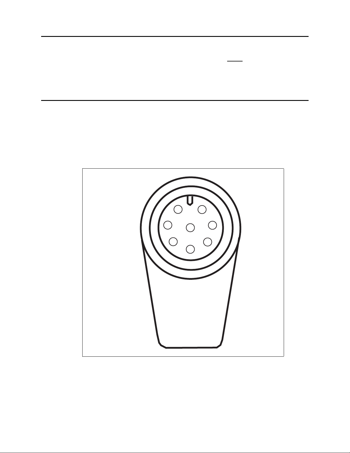
Attaching the cable harness to the MSU
The cable harness plugs into the lower corner of the MSU.
To plug in the cable:
1 Make sure the connector on the cable harness is fully seated to the MSU connector.
2 Turn the outer shell of the cable harness connector clockwise until the connector locks
into place.
Figure 3 shows the connector and its pins.
1
2
7
8
6
Figure 3 MSU connector
3
4
5
6 Installing the mobile subscriber unit
Page 13

Table 1 describes the MSU connector’s pins.
Table 1 Wiring diagram for MSU connector
Pin number Purpose
1 EN TX+
2 EN TX-
3 EN RX+
4 EN RX-
5power
6n/c
7ground
8n/c
Connecting the MSU to the computer
To connect the MSU to the computer:
1 Use the RJ-45 plug on the cable harness into the RJ-45 coupler which is supplied in the
installation kit.
2 Connect an RJ-45 cable from the computer into the other end of the coupler.
Figure 4 illustrates the pins for the RJ-45 connector on the cable harness.
P1 P8
Figure 4 Cable harness — RJ-45 connector’s pins
Table 2 describes the function of the pins.
Table 2 Function of pins on RJ-45 connector
Pin Function
1 EN RX + (white/orange
2EN RX - (orange)
3 EN TX+ (white/green)
4n/c
5n/c
6EN TX- (green)
7n/c
8n/c
7
Page 14

8 Installing the mobile subscriber unit
Page 15

I
NDEX
A
antenna 4
B
bracket
mounting 3
C
cabling diagram for LPB 2
G
grounding
MSU 6
M
Mounting bracket for MSU 3
MSU
mounting bracket 3
MSU connector pin diagran 7
pin diagram
MSU connector 7
RJ-45 connector 7
power cable
preparing for installation 5
RJ-45 connector 7
P
R
9
Page 16

10 Installing and using the Expedience OSU
 Loading...