

Page 1
STEREO CHASSIS
TV
MONO PLUS
GB Service manual
@ Service-Manual
(32 Serviceanvisning
NOKIA
34
@I Manuel de service
(I% Manuale di servizio
5556 6356
1995
7156
CONNECTING PEOPLE
Page 2
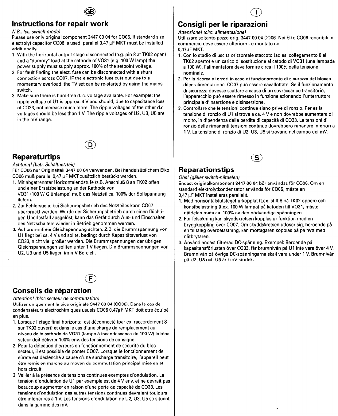
Instructions for repair work
N.6.: (cc. switch-model
Please use only original component 3447 00 04 for CO06. If standard size
electrolyt capacitor COO6 is used, parallel 0,47 FF MKT must be installed
additionally.
1. With the horizontal output stage disconnected (e.g. pin 8 at TK02 open)
and a “dummy” load at the cathode of V031 (e.g. 100 W lamp) the
power supply must supply approx. 100% of the setpoint voltage.
2. For fault finding the elect. fuse can be disconnected with a shunt
connection across CO07. IF the electronic fuse cuts out due to a
momentary overload, the TV set can be re-started by using the mains
switch.
3. Make sure there is hum-free d. c. voltage available. For example: the
ripple voltage of Ul is approx. 4 V and should, due to capacitance loss
nf CO33. nnt increase much more. The rioole voltaoes of the other d.c.
_. ____, ..- _..._._ -__ ..-_.. ..-._.
voltages should be less than 1 V. The ripple voltages of U2, U3, U5 are
in the mV range.
rr_ ._ ._LI__ _
Reparatutiips
Achtung! (betr. Schaltnetzteill
Fiir COO6 nur Originalteil 3447 00 04 verwenden. Bei handelsiiblichem Elko
COO6 mul3 parallel 0,47 FF MKT zusltzlich besttickt werden.
1. Mit abgetrennter Horizontalendstufe (z.B. AnschluB 8 an TK02 offen)
und einer Ersatzbelastung an der Kathode von
V031 (100 W Glijhlampe) muR das Netzteil ca. 100% der Sollspannung
liefern.
2. Zur Fehlersuche bei Sicherungsbetrieb des Netzteiles kann COO7
iiberbrtickt werden. Wurde der Sicherungsbetrieb durch einen fltichtigen ijberlastfall ausgel6st. kann das Gerit durch Aus- und Einschalten
des Netzschalters wieder in Betrieb genommen werden.
3. Auf brummfreie Gleichspannung achten. Z.B. die Brummspannung von
Ul liegt bei ca. 4 V und sollte, bedingt durch KapazitCtsverlust von
C033, nicht viel grdRer werden. Die Brummspannungen der ijbrigen
Gleichspannungen sollten unter 1 V liegen. Die Brummspannungen von
U2, U3 und U5 liegen im mV-Bereich.
Consigli per le riparazioni
Attenzione! (circ. alimentazionel
Utilizzare soltanto pezzo orig. 3447 00 04 CO06. Nei Elko COO6 reperibili in
commercio deve essere ulteriorm. e montato un
0,47pF MKT.
1. Con lo stadio di uscita orizzontale staccato (ad es. collegamento 8 al
TK02 aperto) e un carico di sostituzione al catodo di V031 (una lampada
a 100 W), I’alimentatore deve fornire circa il 100% della tensione
nominale.
2. Per la ricerca di errori in case di funzionamento di sicurezza del blocco
dileeralimentazione, COO7 pub essere cavallottato. Se il funzionamento
di sicurezza dovesse scattare a causa di un sovraccarico transitorio,
I’apparecchio pub essere rimesso in funzione azionando I’unterruttore
principale d’inserzione e disinserzione.
‘z rnntrnll=rn ,-hn la t~neinni mntinlua ciann n&m rli mn7in Pmr me 1.
V. ““IILIVIIUI” Yll” I” LYII”I”III IVII~IIIUI “l”lI” y,,.u “I I”I.LI”. I “I “1 .”
tensione di ronzio di Ul si trova a ca. 4 V e non dovrebbe aumentare di
molto, in dipendenza della perdita di capacite di C033. Le tensioni di
ronzio delle rimanenti tensioni continue dovrebbero rimanere inferiori a
1 V. La tensione di ronzio di U2, U3, U5 si trovano nel campo dei mV.
Reparationstips
Ohs! lgiller switch-nltdelenl
Endast originalkomponent 3447 00 04 bBr anvlndas f6r CO06. Om en
standard elektrolytkondensator anvlnds f6r CO06, m&ste en
0,47 FF MKT installeras parallellt.
1. Med horisontalslutsteget urkopplat (t.ex. stift 8 p8 TK02 ijppen) och
konstbelastning (t.ex. 100 W lampa) pd katoden till V031, mlste
nstdelen mata ca, 100% av den nijdvlndiaa soinninoen,
2. F6r felsijkning kan skyddskretsen kopplas ur funktion med en
bryggkoppling Bver CO07. Om skyddskretsen utl6ser sig, beroende pa
en tillflllig Bverbelastning, kan mottagaren kopplas pB pB nytt med
nltbrytaren.
3. Anvtind endast filtrerad DC-spinning. Exempel: Beroende pB
kapasitansfijrlusten aver C033, fdr brumniven pB Ul inte vara dver 4 V.
Brumniven pd iivriga DC-splnningarna skall vara under 1 V. Brumniven
pB U2, U3 och U5 Br i mV storlek.
Conseils de reparation
Attention! (bloc secteur de commutationl
Utiliser uniquement la pice originale 3447 00 04 (COO6). Dans le cas de
condensateurs electrochimiques usuels COO6 0,47pF MKT doit etre equip6
en plus.
1. Lorsque 1’6tage final horizontal est dbconnectb (par ex. raccordement 8
sur TK02 ouvert) et dans le cas d’une charge de remplacement au
niveau de la cathode de V031 (lampe B incandescence de 100 W) le bloc
seteur doit delivrer 100% env. des tensions de consigne.
2. Pour la detection d’erreurs en fonctionnement de s&uritb du bloc
secteur, il est possible de ponter CO07. Lorsque le fonctionnement de
sDrete est d&lenchb B cause d’une surcharge transitoire, I’appareil peut
gtre remis en marche au moyen du commutation principal mise en et
hors circuit.
3. Veiller B la presence de tensions continues exemptes d’ondulation. La
tension d’onduiation de Ui par exempie est de 4 V env. et ne devrait pas
beaucoup augmenter en raison d’une perte de capacite de C033. Les
tensions d’ondulation des autres tensions continues devraient toujours
dtre infbrieures B 1 V. Les tensions d’ondulation de U2, U3, U5 se situent
dans la gamme des mV.
Page 3
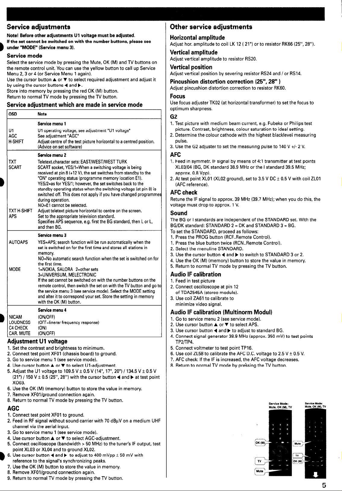
Service adjustments
Note! Before other adjustments Ul voltage must be adjusted.
If the set cannot be switched on with the number buttons, please see
under “MODE” (Service menu 3).
Service mode
Select the service mode by pressing the Mute, OK (M) and TV buttons on
the remote control unit. You can use the yellow button to call up Service
Menu 23 or 4 (or Service Menu 1 again).
Use the cursor button A or v to select required adjustment and adjust it
by using the cursor buttons 4 and p.
Store into memory by pressing the red OK (M) button.
Return to normal TV mode by pressing the TV button.
Service adjustment which are made in service mode
DSD
Ul
4GC
H-SHIFT
TXT Teletextcharacter sets: EASTIWESTMIESTTURK
SCART
TXT H-SHIFT Adjust teletext picture horizontal to centre on the screen.
APS Set to the appropriate television standard.
AUTOAPS
MODE
NICAM (ON/OFF)
LOUDNESS (OFF=linerar frequency response)
C4 CHECK
CAR. MUTE (ON/OFF)
Adjustment Ul voltage
1. Set the contrast and brightness to minimum.
2. Connect test point XFOl (chassis board) to ground.
3. Go to service menu 1 (see service mode).
4. Use cursor button A or v to select Ul-adjustment.
5. Adjust the Ul voltage to 109.5 V + 0.5 V (14”, 17”, 20”) / 134.5 V f 0.5 V
(21”) / 150 V f 0.5 (25”, 28”) with the cursor button 4 and p at test point
x003.
6. Use the OK(M) (memory) button to store the value in memory.
7. Remove XFOl/ground connection again.
8. Return to normal TV mode by pressing the TV button.
AGC
1. Connect test point XFOI to ground.
2. Feed in RF signal without sound carrier with 70 dBuV on a medium UHF
channel via the aerial input.
3. Go to service menu 1 (see service mode).
4. Use cursor button A or v to select AGC-adjustment.
5. Connect oscilloscope (bandwidth > 50 MHz) to the tuner’s IF output, test
point XL03 or XL04 and to ground XL02
6. Use cursor button 4 and) to adjust to 400 mVpp f 50 mV with
reference to the signal’s synchronizing peaks.
7. Use the OK (M) button to store the value in memory.
8. Remove XFOl/ground connection again.
9. Return to normal TV mode by pressing the TV button.
Note
Service menu 1
Ul operating voltage, see adjustment “Ul voltage”
See adjustment “AGC”
Adjust centre of the test picture horizontal to a centred position.
(Advice on set software)
Service menu 2
SCART socket, YES/l=When a switching voltage is being
received at pin 8 (+I2 V), the set switches from standby to the
“ON” operating status (programme memory location El).
YES/S=as for YES/l; however, the set switches back to the
standby operating status when the switching voltage fat pin 8) is
switched off. This does not apply if you have changed programmE
during operation.
NO=El cannot be selected.
Specifies APS sequence, e.g. first the BG standard, then L or L,
and then BG.
Service menu 3
YES=APS; search function will be run automatically when the
set is switched on for the first time and stores all stations in
memory.
NO=No automatic search function when the set is switched on for
the first time.
l=NOKIA, SALORA 2=other sets
3=UNIVERSUM, MELECTRONIC
If the set cannot be switched on with the number buttons on the
remote control, then switch the set on with the TV button and got
the service menu 3 (see service mode). Select the MODE setting
and alter it to correspond your set. Store the setting in memory
with the OK (MI button.
Service menu 4
(ON)
Other service adjustments
Horizontal amplitude
Adjust hor. amplitude to coil LK 12 ( 21”) or to resistor RK66 (25”. 28”).
Vertical amplitude
Adjust vertical amplitude to resistor RS20.
Vertical position
Adjust vertical position by severing resistor RS24 and/or RS14.
Pincushion distortion correction (25”. 28” 1
Adjust pincushion distortion correction to resistor RK60.
Focus
Use focus adjuster TK02 (at horizontal transformer) to set the focus to
optimum sharpness.
G2
1. Test picture with medium beam current, e.g. Fubeka or Philips test
picture. Contrast, brightness, colour saturation to ideal setting.
2. Determine the colour cathode with the highest blacklevel measuring
pulse.
3. Use the G2 adjuster to set the measuring pulse to 140 V t/- 2 V.
AFC
1. Feed in symmetr. IF signal by means of 4:l transmitter at test points
XLO3/04 (BG, DK standard 38.9 MHz or the I standard 39.5 MHz;
approx. 0.8 Vpp).
2. At test point XL01 (XL02 ground), set to 3.5 V DC f 0.5 V with coil ZLOl
(AFC reference).
AFC check
Retune the IF signal to approx. 39 MHz (39.7 MHz); when you do this, the
voltage must drop to approx. 1 V.
Sound
The BG or I standards are independent of the STANDARD set. With the
BG/DK standard: STANDARD 2 = DK and STANDARD 3 = BG.
To set the STANDARD, proceed as follows:
1. Press the PROG button (RCF..Remote Control).
1. Press the blue button twice (RCN..Remote Control).
2. Select the menuline STANDARD.
3. Use the cursor button 4 and p to switch to STANDARD 3 or 2.
4. Use the OK (M) (memory) button to store the value in memory.
5. Return to normal TV mode by pressing the TV button.
Audio IF calibration
1. Feed in test picture
2. Connect oscilloscope at pin 12
of TDA2545A (stereo module).
3. Use coil ZA61 to calibrate to
minimize video signal.
Audio IF calibration (Multinorm Modul)
1. Go to service menu 2 (see service mode).
2. Use cursor button A or v to select APS.
3. Use cursor button 4 and p to adjust to standard BG.
4. Connect signal generator 38.9 MHz (approx. 350 mV) to test points
TP2/TP4.
5. Connect voltmeter to test point TP16.
6. Use coil ZL58 to calibrate the AFC D.C. voltage to 2.5 V + 0.5 V.
7. AFC check: If the IF is increased, the AFC voltage decreases.
8. Return to normal TV mode by pressing the TV button.
Page 4

4-j
I
-
Page 5
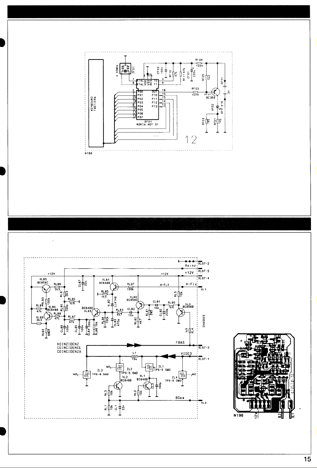
KOINZIDENZ
COINCIDENCE
COINCIDENZA
Page 6

I-
___...____.._.__._____________________________________._______---...............__._.________....___._......_..........._...
,3
Page 7

r
:1..r . ..I) (I .I
I
x
(
t
ii&T+
Ta
-
Page 8

CA03 220n
CA81
37
RIB3 .k7
RIB2
n
4k7
12”
TON-ZF/IF/MF
RA00 lOOR
ANA-1K?+ 8C2-OUT-R
.
_ _
3-10
DACA-L
DACA-R
C-CACI-L
C-DACS-R
DACY-L
DACY-R
1
CA3 w
Page 9

‘” RESET
9
____________________________----_________________________
MUTE
Page 10

CA53 220n
--_(W
CA81 220”
RAW 4k7
U
RIB2 4k7
5”
P
12”
RESET
RAW IOOR
I
NAB0
YW34,O
SOUND PROCESSOR
Page 11

VA73
ec800~:
r
t
L_______________________________________---------________.
Page 12

Mono Plus 110” Stereo Chasgis
BElJIENTEIL/
SF01
BDIII (2” BOlllI 0”
801 12” BDlllIl, 0”
I\
%%YY PPrnfT YTSS
T> >>>
\
AFC SWITCH
SCHALTNETZTEIL/SWITCH MODE /CIRC.ALIMENTAZIONE
v Waveforms referenced to earth on TEA 2164 G pin 1 ect./ Oszillogramm-MeRpunkt auf Masse an TEA 2164 G Pin 1 etc. bezogen./
Tous le oszillogrammes se rapportant a la masse TEA 2164 G pin l./ Riferire tutti gli oscillogrammi alla massa TEA 2164 G pin 1./
M&a puiser mot TEA 21646: jord, stift 1.
93I)m
Toutes les mesures se rapportal
rete P/ Mltta mot nltdelens mi
Page 13

C.A.F.
After DFOZ has been replaced, the AGC must also be recalibrated.
Nach Austausch van DFOZ mu!3 such die AGC neu abgeglichen werden.
Apr&s avoir remplacC DFOZ, AGC doit Cgalement etre r&quilibrCe.
Dopo aver sostituito il DFOZ B necessario equilibrare nuovamente anche I’ AGC.
AGC: n m&Se ocks& justetas nlr DF02 byts.
Direction arrow/ Richtungspfeil q
IT/MAINS-INSULATEWSEPARATO OALLA RETE
________________________________________________________~~~______________________________~___________-..__-_____-------__-.~~__________________________________________--~~~_~~~__.
Fleche de direction/ Freccia di direzione
asurements referenced to switch-moded power supply minus potential P / Messungen auf Schaltnetzteil-Minuspotential II bezogen
, les mesures se rapportant au potentiel negatif du bloc-secteur de commutation Jl / Riferire tutte le misure al potenziale negativo della sezione di
/ Mltta mot nltdelens minuspotential Y
A
Page 14

I
bc
tu
.
._____________________________________~________________________~~~~~~~~~~~~~~______~____________________________________________________
-_---___________
I
lie
SIGNAL-PROCESSOR
PROCESSORE SEGNAL
,
I
>i
:I
I
C.R.T. base
Connexion
5858 20 41, ..42,
I_
‘4:
HOR.ABLENKUNG
HOR.OEFLECTION
OEFLESSIONE ORIZZ.
$ Depending on the chassis version, these components can either be fitted or not.
Diese Bauteile konnen je nach Chassisversion bestiickt/ nicht bestijckt sein.
Suivant la version du chassis, ces composants sont mantes/ pas mantes.
La possibilita di montaggio di questi componenti dipende dalla versione dello chassis.
137
In standby mode, the
Im Standby-Betrieb
En mode stand-by les
Net funzionamento in
Page 15

CRT. base board/ BildriihrenanschluRplatte/
Connexion tube image/ Collegamento cinescopio
5858 20 41, ..42, ..55
Assembly group abbreviations/ Beugruppenkurzbezeichnungen
Codiflca dei modulil DBsignations abr6g6es des sous-ensembles
Blockf6rkortningar
D = Color decoder/ Decodificatore colore/ Flrgdekoder
K k Deflessione orizzontale/ Hor. deflection/ Horisontal avlankning
S = Verticale/ Vertical
I = AF/ ZF/ HF
L =IF/MF/
F = Control unit/ Unita di comando/ Kontrollenhet
A =Audio
0 = Power supply/ Schaltnetzteil/ Circuit0 aliment. ret& N&de1
H = CRT. board/ Bildr0hrenanschlW Colleg. cinescopio/ Bildr6rsplattan
R = Videotext! Teletext/ Televideo/ Text- TV
STEREO CHASSIS
IlOO
ler be fitted or not.
!sti.ickt sein.
5 mont6s.
versione dello chassis.
In standby mode, the voltages at the switch-mode power supply are approx. 30% of those applying in normal operating mode (except for U5).
Im Standby-Betrieb liegen die Spannungen am Schaltnetzteilausgang bei ca. 30% des Normalbetriebes (at&r U5L
En mode stand-by les tensions appliqees a la sortie du block secteur de commutation s &vent a 30% env. du fonctionnement normal (a part U5L
Net funzionamento in stand-by, all’ altezza dell’ uscita del trasf. di rete le tensioni sono il30% ca. della tensioni net funzion. normale (eccetto U51
 Loading...