

Page 1

Installing and using your
CPE device
Directions for connecting
your CPE to a computer or
LAN and obtaining highspeed Internet and voice
services.
i
Page 2

Expedience is a trademark of NextNet Wireless.
©2000-2001 NextNet Wireless, Inc. All rights reser ved.
NOTICE: This equipment has been tested and found to comply with the Radio Frequency
Radiation Exposure Limits detailed below. A minimum of 20 centimeters (8 inches) separation
between the CPE and the operator and all other persons should be maintained.
Radio Frequency Radiation Exposure Limits
TABLE 1. Limits for Maximum Permissible Exposure (MPE)
Frequency range
(MHz)
0.3-3.0 614 1.63 *(100) 6
3.0-30 1842/f 4.89/f
30-300 61.4 0.163 1.0 6
300-1500 — — f/300 6
1500-100,000 — — 5 6
0.3-1.34 614 1.63 *(100) 30
1.34-30 824/f 2.19/f
30-300 27.5 0.073 .2 30
300-1500 — — f/1500 30
1500-100,000 — — 1.0 30
f = frequency in MHz
* = Plane-wave equivalent power density
NOTE 1 TO TABLE 1: Occupational/controlled limits apply in situations in which persons are
exposed as a consequence of their employment provided those persons are fully aware of the
potential for exposure and can exercise control over their exposure.
Limits for occupational/controlled exposure also apply in situations when an individual is transient
through a location where occupational/controlled limits apply provided he or she is made aware of
the potential for exposure.
NOTE 2 TO TABLE 1: General population/uncontrolled exposures apply in situations in which
the general public may be exposed, or in which persons that are exposed as a consequence of their
employment may not be fully aware of the potential for exposure or can not exercise control over
their exposure.
Note: This equipment has been tested and found to comply with the limits for a Class A digital
device, pursuant to par t 15 of the FCC rules. These limits are designed to provide reasonable
protection against harmful interference when the equipment is operated in a commercial
environment. This equipment generates, uses, and can radiate radio-frequency energy, and, if not
installed and used in accordance with the installation manual, may cause harmful interference to
radio communications. Operation of this equipment in a residential area is likely to cause harmful
interference, in which case users will be required to correct the interference at their own expense.
THE SPECIFICATIONS AND INFORMATION REGARDING THE PRODUCTS IN THIS
MANUAL ARE SUBJECT TO CHANGE WITHOUT NOTICE. ALL STATEMENTS,
INFORMATION, AND RECOMMENDATIONS IN THIS MANUAL ARE BELIEVED TO
BE ACCURATE BUT ARE PRESENTED WITHOUT WARRENTY OF ANY KIND. USERS
MUST TAKE FULL RESPONSIBILITY FOR THEIR APPLICATION OF ANY PRODUCT.
NOTWITHSTANDING ANY OTHER WARRANTY HEREIN, ALL DOCUMENT FILES
AND SOFTWARE ARE PROVIDED “AS IS” WITH ALL FAULTS. NEXTNET WIRELESS
DISCLAIMS ALL WARRANTIES, EXPRESSED OR IMPLIED, INCLUDING, WITHOUT
LIMITATION, THOSE OF MERCHANTABILITY, FITNESS FOR A PARTICULAR
PURPOSE AND NONINFRINGEMENT OR
Electric field
strength (V/m)
(A) Limits for Occupational/Controlled Exposures
(B) Limits for General Population/Uncontrolled Exposure
Magnetic field
strength (A/m)
Power density
(mW/cm 2)
2
)
*(900/f
2
*(180/f
)
Averaging time
(minutes)
6
30
ii
Page 3

ARISING FOM A COUSRE OF DEALING, USAGE, OR TRADE PRACTICE.
IN NO EVENT SHALL NEXTNET WIRELESS OR ITS SUPPLIERS BE LIABLE FOR ANY
INDIRECT, SPECIAL, CONSEQUENTIAL, OR INCIDENTAL DAMAGES, INCLUDING,
WITHOUT LIMITATION, LOST PROFITS OR LOSS OF DAMAGE TO DATA ARISING
OUT OF THE USE OR INABILITY TO USE THIS MANUAL, EVEN IF NEXTNET
WIRELESS HAS BEEN ADVISED OF THE POSSIBILITY OF SUCH DAMAGES.
iii
Page 4

iv
Page 5

Contents
Welcome! ....................................................................................... 1
Before You Begin ....................................................................... 1
Connecting your CPE to a computer or LAN ......................................... 4
Installation Overview .................................................................. 4
Setting up the computer to dynamically receive an IP address ......... 4
Windows 95, Windows 98, Windows NT: Setting up the network
connection ................................................................................ 5
Windows 2000: Setting up the network connection ......................... 5
Connecting the CPE to a Computer or Network ............................... 6
Connecting the CPE to a computer ............................................... 6
Connecting the CPE to a network ................................................. 7
Supplying Power to the CPE ........................................................ 8
Finding the Strongest Service Provider Signal ................................ 8
Using the Software-Assisted Method to Find the Strongest Signal ..... 9
Using the LEDs to find the Strongest Service Provider Signal ..........12
Troubleshooting.............................................................................. 18
LEDs that don’t blink, but rather chase ........................................18
The LEDs on the CPE blink more slowly than normal ......................19
You receive a dialog box indicating that you cannot connect to your
service provider ........................................................................19
I can successfully contact my service provider at home, but not at
work or at a friend’s house .........................................................20
If You have Problems Getting Connected ......................................20
Congratulations! ............................................................................. 21
Page 6

vi
Page 7

Welcome!
This document describes how to install and use your
customer premise equipment (CPE), which provides you
with high speed internet services.You can connect your
CPE to your computer, or you can connect it to a small
office/home office (SOHO) local area network (LAN)
through a hub, switch, gateway, or router.
BEFORE YOU BEGIN
• Make sure your computer is equipped with an Ether-
net network interface card (NIC).
• The Ethernet cable that is supplied with your CPE
plugs into any standard Ethernet NIC. The NIC is
not provided with the CPE, but you can purchase
a NIC at most computer and electronics stores.
• Find an appropriate location for your CPE.
• Make sure you are operating the CPE above
ground level. The CPE works best when installed
on the 1st floor or above, near an outside window.
It may not function optimally when installed in a
basement.
• The CPE uses a standard power supply and can sit
on a desktop or shelf. You need to locate the CPE
close to a power source and to your computer (or
to your network device, if applicable).
• If you choose to place the CPE a good distance
from your computer, you may need to purchase a
longer Ethernet cable. The supplied cable is 6 feet
(1.83 meters) long.
Make sure the longer cable that you might purchase
is flexible enough to bend under the bottom of the
CPE.
• Locate the components shipped with your CPE
device:
• CPE device
1
Page 8
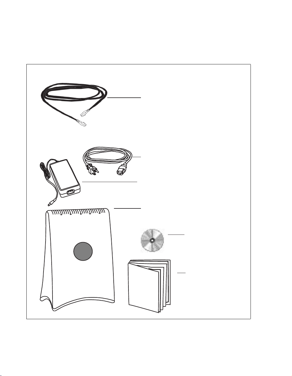
•Software CD-ROM
• Power cable and power supply
•Ethernet cable
Figure 1 illustrates the CPE package contents.
Ethernet cable
Power cable
Power supply
CPE device
Software CD-ROM
C
P
E
I
n
s
t
a
l
l
CPE Installation Guide
Figure 1: CPE package contents
2
Page 9

Table 1 lists the standard contents in your CPE package.
Table 1 CPE package components
Component Part number
CPE device 123-0010-1000
Power supply 420-0010-1000
Power cord 420-0010-1001
CPE installation guide 104-0010-0002
Installation software CD-ROM 150-0010-0001
Ethernet cable 597-6010-0001
3
Page 10

Connecting your CPE to a computer or LAN
INSTALLATION OVERVIEW
The installation consists of the following major tasks, each
of which is explained in greater detail in the sections that
follow:
1 After ensuring your Ethernet NIC is installed properly,
make sure your computer is set up to automatically
obtain an IP address.
2 Perform one of the following:
• If you are connecting the CPE directly to your
computer, use the supplied Ethernet cable to do
so.
• If you are connecting the CPE to a hub or switch,
use an Ethernet cable appropriate for your network
device. This might be a straight through or crossover cable, depending on how your network device
switches signals. The CPE device operates as a hub
or a bridge. The supplied cable is a straight through
cable.
1
4
3 Supply power to the CPE.
4 Scan for the best signal from your service provider.
SETTING UP THE COMPUTER TO DYNAMICALLY
RECEIVE AN IP ADDRESS
You must set up your computer so that the computer can
communicate with the CPE. To do so, make sure your
computer is set up to dynamically receive an IP address.
• If you are running Windows 95, Windows NT, or
Windows 98, go to “Windows 95, Windows 98, Windows NT: Setting up the network connection‚” on
page 5.
Page 11

1A
• If you are running Windows 2000, go to “Windows
2000: Setting up the network connection‚” on page 5.
• If you don’t see your operating system listed here,
check the system’s help file. Most explain how to set
up a system to dynamically receive an IP address.
WINDOWS 95, WINDOWS 98, WINDOWS NT:
ETTING UP THE NETWORK CONNECTION
S
1 From the Start menu, select Settings. Then select
Control Panel.
2 In the window that appears, double click the Network
icon.
3 Select the TCP/IP entry for the NIC.
4 Click Properties.
5 Select the IP Address tab.
6 Activate the Obtain an IP Address automatically
radio button.
7 To close the windows, click OK.
1B
8 Reboot the computer.
WINDOWS 2000: SETTING UP THE NETWORK
CONNECTION
1 From the Start menu, select Settings. Then select
Network and Dial-up Connections.
2 Right click the connection you want to alter; that is, the
name of your NIC. From the pop-up menu, select
Properties.
3 The Local Area Connection Properties window
appears. Select the Internet Protocol (TCP/IP) item.
Click Properties.
4 In the window that appears, activate the Obtain an IP
address automatically radio button. To close the
5
Page 12

2
2A
window, click OK. On the remaining open window,
click OK again.
CONNECTING THE CPE TO A COMPUTER OR
ETWORK
N
You can connect the CPE directly to a computer, or you
can connect it to a small office/home office (SOHO)
network.
• If you are directly connecting the CPE to your com-
puter, go to step 2A.
• If you are connecting the CPE to a network, go to
step 2B.
CONNECTING THE CPE TO A COMPUTER
Use the supplied Ethernet cable to connect the CPE to
your computer, as follows:
1 On the bottom of the CPE, locate the CPE Ethernet
jack. Plug one end of the Ethernet cable into the CPE
6
Page 13

Ethernet jack.
Figure 2: Ethernet Jack Location on
Bottom of CPE
2B
2 On your computer, locate the NIC jack. Plug the other
end of the Ethernet cable into the NIC.
CONNECTING THE CPE TO A NETWORK
Note: Plan to use only one CPE on a network. Do not
use multiple CPEs on the same network.
If you directly connect a CPE to a computer, you use the
supplied Ethernet cable (also known as a straight through
cable).
However, to connect the CPE to a hub or switch, use an
Ethernet cable appropriate for your network device. This
might be a straight through or cross-over cable, depending
on how your network device switches signals. When
determining how to set up your network, remember that
the CPE device operates as a hub or a bridge.
7
Page 14

3
SUPPLYING POWER TO THE CPE
1 Plug the power cable into the power supply, then into
the wall outlet.
2 Plug the cable from the power box into the CPE’s
power jack, located on the bottom of the CPE.
4
8
Figure 3: Power Jack Location on
Bottom of CPE
When the CPE has a proper power supply, the light
emitting diodes (LEDs) on top of the CPE light.
FINDING THE STRONGEST SERVICE PROVIDER
IGNAL
S
Your CPE is equipped with an internal, directional
antenna. To provide you with the best service, your CPE
searches for the strongest signal transmitted by your
service provider.
You can find the strongest service provider in your area
using one of the following methods:
Page 15

• Software-assisted method (available for Windows
operating systems only)
• LED method (available for any operating system)
Regardless of the method you use, you need to understand
which sides of the CPE are its front, back, top, and bottom.
Figure 4 illustrates the CPE sides.
top
backfront
4A
bottom
Figure 4: CPE sides
USING THE SOFTWARE-ASSISTED METHOD TO
IND THE STRONGEST SIGNAL
F
To use the software program to help you search for the
strongest service provider signal in your area:
1 Locate the software CD supplied with your CPE. Insert
the CD into your computer’s CD drive and run the
Setup program.
2 After the software installs, run the program. The CPE
9
Page 16

Scan window (Figure 5) appears.
Figure 5: CPE Scan window
3 With CPE in hand, stand in front of the window in the
room where you plan to operating the CPE.
To scan for the strongest signal, you will rotate the front
of the CPE in a 180 degree path in front of the window,
much like moving the small hand of a clock to 9:00,
10
Page 17

10:30, 12:00, 1:30, and 3:00.
Figure 6: Orienting CPE front during signal scan
4 To start a scan for signals from your service provider,
click Start. Hold the front of the CPE at the 9:00
position for about 5 seconds.
The CPE searches for a signal from your service
provider, as indicated by the blinking of LEDs on the
CPE.
Note: In most cases, the LEDs on the CPE blink on and
off. However, if a service provider cannot be found
in your area, the CPE’s LEDs chase each other —
11
Page 18

that is, an LED blinks on as the previous LED
blinks off. For more information, refer to the
section “LEDs that don’t blink, but rather
chase‚” on page 18.
5 When the CPE finds a signal, a dialog box displays the
strength of the signal.
6 To continue your search for the strongest signal, turn
your CPE slowly in a semi-circle, stopping at the 10:30,
12:00, 1:30 and 3:00 positions.
7 Note the signal strength at each position. The stronger
the signal, the more LEDs on the right-side of the
device are lit.
8 Remembering the strongest signal reported, re-orient
your CPE to the direction it was pointed when the
strongest signal was found.
9 To make sure your CPE is registered with your service
provider, wait for the left-most LED on the CPE to be
continuously lit. Click Stop Scan.
You’ve now found the strongest signal in your area. You
only need to re-run the GetConnected program and repeat
the scan when you power down your CPE and move it.
4B
12
USING THE LEDS TO FIND THE STRONGEST
ERVICE PROVIDER SIGNAL
S
You can find the strongest service provider signal by using
the LEDs on top of the CPE. You can use this method
Page 19

regardless of the operating system your computer runs.
LEDs on CPE
Figure 7: Location of LEDs on CPE
13
Page 20

To use the LEDs to find the strongest service provider
signal:
1 If you have plugged the Ethernet cable into the bottom
of the CPE, disconnect the Ethernet cable now.
2 Make sure the CPE’s power cord is connected to the
CPE and to a power source. If your CPE has power, the
LEDs on the CPE begin to blink on and off.
3 With CPE in hand, stand in front of the window in the
room where you plan to operating the CPE.
To scan for the strongest signal, you will rotate the front
of the CPE in a 180 degree path in front of the window,
much like moving the small hand of a clock to 9:00,
10:30, 12:00, 1:30, and 3:00.
14
Page 21

Figure 8: Orienting CPE front during signal scan
4 Start the scan by holding the front of the CPE at the
9:00 position for about 5 seconds.
5 Check the LEDs on the top of the CPE. The LEDs
blink, and indicate the strength of the signal received
from your service provider.
The stronger the signal from the service provider, the
more LEDs on the device are lit; for example, if all 5
LEDs are lit, the signal from the service provider is very
15
Page 22

5 LEDs blink on
strong. If only 1 LED is lit, the signal is weaker.
6 Rotate the front of the CPE to the 10:30 position. At
the 10:30 position, stop the rotation for about 5
seconds.
Again, the LEDs blink, indicating the strength of the
signal received from your service provider.
7 Continue to rotate the CPE as described in step 6,
stopping at the positions of 12:00, 1:30, and 3:00.
Note the signal strength at each rotation. Again, the
stronger the signal, the more LEDs on the CPE blink
on and off.
16
5 LEDs blink off
5 LEDs blink on
Figure 9: LEDs on CPE indicating service provider
signal strength (example)
Note: In most cases, the LEDs on the CPE blink on and
off. However, if a service provider cannot be found
Page 23

in your area, the CPE’s LEDs chase each other —
that is, an LED blinks on as the previous LED
blinks off. For more information, refer to the
section “LEDs that don’t blink, but rather
chase‚” on page 18.
8 After you’ve completed the rotation, re-orient the front
of the CPE to the direction it was pointed when the
strongest signal was found.
9 Plug in the Ethernet cable jack on the bottom of the
CPE. The CPE then registers with your service
provider.
10 When your CPE is registered, the LEDs on the CPE are
continuously lit. You can now use the device to obtain
high-speed internet services.
If you power down your CPE and move it, you must
repeat this procedure to find another signal.
17
Page 24

Troubleshooting
This section describes common issues with CPE
installation, and how to resolve the issues if you encounter
them.
LEDS THAT DON’T BLINK, BUT RATHER CHASE
If your CPE is unable to find a service provider signal, the
LEDs on your CPE don’t blink, but rather they “chase”
each other, with an LED blinking on as the previous LED
blinks off. Figure 10 illustrates LEDs in chase mode.
18
Figure 10: LEDs on CPE indicating no service provider
found (chasing LEDs)
For further information about connecting, contact your
service provider.
Page 25

THE LEDS ON THE CPE BLINK MORE SLOWLY
THAN NORMAL
When your CPE searches for a service provider signal, the
LEDs on the CPE blink on and off rapidly. If you notice
the CPE’s LEDs blinking more slowly than usual, this
usually indicates that your CPE is trying to register with
your service provider.
During registration, your service provider may be checking
records to indicate that you are a valid user of the service
provider’s system. In most cases, the registration process
happens so quickly you hardly notice a change in the blink
rate of the LEDs on your CPE.
However, if the lights blink slowly for an extended time
(more that 30 seconds):
1 Unplug the Ethernet cable from the bottom of the
CPE.
2 Re-plug the cable back in.
3 Repeat the procedure described in the section “Using
the LEDs to find the Strongest Service Provider
Signal‚” on page 12.
4 Perform one of the following:
• If your CPE successfully registers, as indicated by
continuously lit LEDs, you can use your connection.
• If the LEDs on your CPE continue to slowly blink
on and off, contact your service provider.
YOU RECEIVE A DIALOG BOX INDICATING THAT
YOU CANNOT CONNECT TO YOUR SERVICE
PROVIDER
When you try to connect with your service provider, you
may receive a message on your computer indicating that
you cannot connect at this time.
You may receive this message for any number of reasons,
such as the service provider’s equipment may be
19
Page 26

malfunctioning, your CPE is malfunctioning, or your
service provider is still processing your payment or
identification records.
If you receive such a message:
1 Make a note of the message’s contents and any error
number that appears.
2 Contact your service provider with this information.
They should be able to resolve the problem for you.
I CAN SUCCESSFULLY CONTACT MY SERVICE
PROVIDER AT HOME, BUT NOT AT WORK OR AT A
FRIEND’S HOUSE
You need to repeat the search for a service provider signal
each time you power down your CPE and move it.
If you have not repeated the signal search, do so.
If this does not solve the problem, check with your service
provider to make sure they offer service to the geographic
location from which you are running your CPE.
20
IF YOU HAVE PROBLEMS GETTING CONNECTED
Contact the electronics or computer store where you
purchased the CPE, or contact your service provider, using
the contact information on the back cover of this guide.
Page 27

Congratulations!
After successfully completing these steps, you can use your
CPE to obtain high speed, high quality internet and voice
services for your home or small office.
STAMP OR PRINT CONTACT INFORMATION
HERE.
21
Page 28

22
 Loading...