

Page 1

MF Manager C2.5
User's Manual
C33846.87.A1
DN00276927 © Nokia Networks Oy 1 (274)
Issue 1-0 en Nokia Proprietary and Confidential
Page 2

MF Manager C2.5
The information in this document is subject to change without notice and describes only the
product defined in the introduction of this documentation. This document is intended for the
use of Nokia Networks' customers only for the purposes of the agreement under which the
document is submitted, and no part of it may be reproduced or transmitted in any form or
means without the prior written permission of Nokia Networks. The document has been
prepared to be used by professional and properly trained personnel, and the customer
assumes full responsibility when using it. Nokia Networks welcomes customer comments as
part of the process of continuous development and improvement of the documentation.
The information or statements given in this document concerning the suitability, capacity, or
performance of the mentioned hardware or software products cannot be considered binding
but shall be defined in the agreement made between Nokia Networks and the customer.
However, Nokia Networks has made all reasonable efforts to ensure that the instructions
contained in the document are adequate and free of material errors and omissions. Nokia
Networks will, if necessary, explain issues which may not be covered by the document.
Nokia Networks' liability for any errors in the document is limited to the documentary correction
of errors. Nokia Networks WILL NOT BE RESPONSIBLE IN ANY EVENT FOR ERRORS IN
THIS DOCUMENT OR FOR ANY DAMAGES, INCIDENTAL OR CONSEQUENTIAL
(INCLUDING MONETARY LOSSES), that might arise from the use of this document or the
information in it.
This document and the product it describes are considered protected by copyright according to
the applicable laws.
NOKIA logo is a registered trademark of Nokia Corporation.
Other product names mentioned in this document may be trademarks of their respective
companies, and they are mentioned for identification purposes only.
Copyright © Nokia Networks Oy 2000. All rights reserved.
2 (274) © Nokia Networks Oy DN00276927
Nokia Proprietary and Confidential Issue 1-0 en
Page 3

Contents
1 About this manual 9
1.1 Typographic conventions 10
2 Introduction to MF Manager C2.5 11
2.1 System architecture 11
2.2 General features 12
2.3 User interface 13
2.4 System requirements 14
2.5 Compatibility 15
2.6 Product codes 15
2.7 Copyright notice 16
3 Installation 17
3.1 General 17
3.2 Installing software 18
4 Authorising the licence 23
4.1 Software licence validation 23
4.2 Authorising a new licence 25
4.3 Upgrading a trial licence 27
4.4 Transferring a licence 27
Contents 3
Summary of changes 7
5 Getting started 35
5.1 Security 35
5.2 Starting MF Manager 37
5.3 Working with configurations 38
5.3.1 Creating a new configuration (off-line) 41
5.3.2 Changing an existing off-line configuration 43
5.3.3 Changing an on-line configuration 44
5.4 Configuring NMS/10 MF and PDH Polling 45
5.4.1 Converting TMC configurations 45
5.4.2 General settings 47
5.4.3 Adding buses 47
5.4.4 Adding network elements 48
5.4.5 Configuring the PDH Manager interface 49
5.4.6 Configuring the OS interface 49
5.4.7 Adding alarm printers 50
5.5 Using online help 50
5.6 Printing 51
5.7 Making backups 52
5.8 Restoring backups 53
5.9 Exiting MF Manager 53
6 Reference 55
DN00276927 © Nokia Networks Oy 3 (274)
Issue 1-0 en Nokia Proprietary and Confidential
Page 4

6.1 About MF Manager dialog box 55
6.2 Add Alarm Classification dialog box 56
6.3 Add Bus dialog box 60
6.4 Add Device Type dialog box 60
6.5 Add Filter dialog box 61
6.6 Add PM Jobs dialog box 67
6.7 Add Station dialog box 67
6.8 Addresses dialog box 68
6.9 Addresses (SUBSET) dialog box 75
6.10 Application window 76
6.10.1 Title bar 77
6.10.2 Menu bar 78
6.10.3 Manage menu 78
6.10.4 Edit menu 85
6.10.5 Configure menu 86
6.10.6 Performance menu 90
6.10.7 View menu 91
6.10.8 Window menu 93
6.10.9 Help menu 94
6.10.10 Toolbar 95
6.10.11 Status bar 96
6.10.12 User input 96
6.10.13 Data validation 97
6.10.14 Clipboard 98
6.10.15 Printing 99
6.10.16 Online help 99
6.10.17 Command line arguments 99
6.11 Auto-discovery Log dialog box 100
6.12 Bus x dialog box 106
6.13 Bus x - Add Address(es)/FE(s) dialog box 122
6.14 Bus x - Add PM Jobs dialog box 129
6.15 Bus x - Addresses to Scan dialog box 134
6.16 Bus x - Modify Address(es)/FE(s) dialog box 135
6.17 Bus x - Move Address(es)/FE(s) dialog box 140
6.18 Bus x Address y - Add PM Jobs 146
6.19 Bus x Address y - Edit PM Jobs dialog box 146
6.20 Bus x Address y FE z - Edit PM Jobs dialog box 147
6.21 Change Configuration Type dialog box 148
6.22 Configuration window 150
6.22.1 Common information 150
6.22.2 Buses tab 152
6.22.3 PDH Manager Interfaces tab 153
6.22.4 OS Interfaces and Printer Spoolers tab 155
6.23 Configuration Type dialog box 157
6.24 Connect dialog box 157
6.25 Fault Status Consistency Check dialog box 160
6.26 Filters and Alarm Classifications dialog box 162
6.27 Font dialog box 169
6.28 Hardware dialog box 169
6.29 MF Manager Window 171
6.30 Modify Address(es)/FE(s) dialog box 171
MF Manager C2.5
4 (274) © Nokia Networks Oy DN00276927
Nokia Proprietary and Confidential Issue 1-0 en
Page 5

6.31 Modify Alarm Classification dialog box 171
6.32 Modify Device Type dialog box 171
6.33 Modify Filter dialog box 171
6.34 Modify Station dialog box 171
6.35 Network Scan dialog box 172
6.36 Network Scan Log dialog box 174
6.37 Network Test Interface dialog box 174
6.38 Open dialog box 176
6.39 OS Interface x dialog box 176
6.40 Page Setup dialog box 186
6.41 PDH Manager Interface x dialog box 189
6.42 PDH Polling General dialog box 195
6.43 Performance Settings dialog box 208
6.44 PM Data Collection Times dialog box 209
6.45 Print Selection dialog box 212
6.46 Printer Spooler x dialog box 216
6.47 Save As dialog box 221
6.48 Select Printer dialog box 221
6.49 Set NT Time dialog box 223
6.50 SNMP Interface dialog box 226
6.51 Subset Definition dialog box 229
6.52 System Command dialog box 232
Appendix A. Connecting Nokia Managers to NMS/10 MF or PDH Polling
workstation 237
A.1 General 237
A.2 MF Manager and NMS/10 MF installation 237
A.3 MF Manager connections 238
A.4 NMS/10 MF and PDH Polling system connections 239
A.5 PM data collection result files 239
Appendix B. Directory hierarchy 240
B.1 MF Manager directory hierarchy 240
B.2 NMS/10 MF and PDH Polling directory hierarchy 243
Appendix C. Configuration report format 245
C.1 General 245
C.2 PDH Polling general information 245
C.3 PM data settings 247
C.4 Hardware information 247
C.5 PDH manager interfaces 247
C.6 OS interfaces 248
C.7 Printer spoolers 249
C.8 SNMP interface 250
C.9 Network Test interface 251
C.10 Buses 251
Appendix D. Network Test Client 255
D.1 Features 255
D.2 Getting started 255
D.2.1 Starting the Network Test Client 256
DN00276927 © Nokia Networks Oy 5 (274)
Issue 1-0 en Nokia Proprietary and Confidential
Page 6

D.2.2 Connecting to a server 256
D.2.3 Uploading addresses for testing 258
D.2.4 Selecting arbitrary addresses for testing 261
D.2.5 Tuning test parameters 262
D.2.6 Viewing test results 265
D.3 User interface 270
D.3.1 Title bar 270
D.3.2 Menu bar 270
D.3.3 Toolbar 271
D.3.4 Status bar 271
D.3.5 User input 272
D.3.6 Data validation 272
D.3.7 Clipboard 272
D.3.8 Test reports 272
D.3.9 Online help 273
MF Manager C2.5
6 (274) © Nokia Networks Oy DN00276927
Nokia Proprietary and Confidential Issue 1-0 en
Page 7
Summary of changes
Document Date Comment
C33846003SE_00 09 Jun 2000 Valid for programs:
P31757.01 - .06 release A
P31757.51 - .56 release A
DN00276927 Issue 1 en 10 Apr 2001 New document numbering scheme adopted.
DN00276927 © Nokia Networks Oy 7 (274)
Issue 1-0 en Nokia Proprietary and Confidential
Page 8

MF Manager C2.5
8 (274) © Nokia Networks Oy DN00276927
Nokia Proprietary and Confidential Issue 1-0 en
Page 9
1 About this manual
This manual is intended for the users of MF Manager C2.5. It covers all the
information you need to start using MF Manager to configure NMS/10 MF or
PDH Polling HW and SW to poll the managed PDH/Primary Rate network.
Note
In this manual both NMS/10 MF and PDH Polling are sometimes referred to as
NMS/10 MF. Note, however, that PDH Polling has some limitations compared to
NMS/10 MF.
About this manual
This User's Manual covers the following topics:
• Introduction (Chapter 2)
• Installation instructions (Chapter 3)
• Authorising the licence (Chapter 4)
• Getting started (Chapter 5)
• Reference (Chapter 6)
• Connecting Nokia Managers to NMS/10 MF or PDH Polling workstation
(Appendix A)
• Directory hierarchy (Appendix B)
• Configuration report format (Appendix C)
• Network Test Client (Appendix D).
We recommend that you read Chapter 5, ’Getting Started’ to get acquainted with
the operation of MF Manager.
Please familiarize yourself with Microsoft Windows NT before operating this
program.
DN00276927 © Nokia Networks Oy 9 (274)
Issue 1-0 en Nokia Proprietary and Confidential
Page 10
For further information see also:
• NMS/10 MF Agent C2.0 Agent Configuration Tool User Manual
• NMS/10 MF C2.0 Operating Manual
• NMS/10 MF C1.0 Operating Manual
• PDH Polling HW C1.0 & SW C2.0 Installation Instructions
• PDH Polling C1.0 Installation Instructions
• Microsoft Windows NT user documentation.
1.1 Typographic conventions
The table below presents the conventions that are used in this MF Manager
User’s Manual:
MF Manager C2.5
Table 1. Typographic conventions
Italic font Indicates a word or phrase that is emphasized, or a
reference to the title of a manual, example:
Refer to the NMS/10 MF Operating Manual.
Bold font Indicates the title of a window, or an option, command,
field or group, or anything that you must type exactly as it
appears, examples:
Help → Index means: choose Index from the
Help menu.
A:\install means: type A:\install
ALL CAPITALS Indicate a directory or file name, example:
INSTALL.EXE
SMALL CAPITALS
1
2
3
Indicate the keys of the terminal keyboard, example:
CTRL
Highlights the start of a procedure.
10 (274) © Nokia Networks Oy DN00276927
Nokia Proprietary and Confidential Issue 1-0 en
Page 11

Introduction to MF Manager C2.5
2 Introduction to MF Manager C2.5
This chapter introduces MF Manager C2.5. It covers the following topics:
• System architecture (Section 2.1)
• General features (Section 2.2)
• User interface (Section 2.3)
• System requirements (Section 2.4)
• Compatibility (Section 2.5)
• Product codes (Section 2.6)
• Copyright notice (Section 2.7).
2.1 System architecture
MF Manager is a Windows NT based application for configuring NMS/10 MF
and PDH Polling.
MF Manager C2.5 runs under Microsoft Windows NT Workstation version 4.0
and is compatible with NMS/10 MF C2.0, NMS/10 MF C1.0, PDH Polling C2.0,
and PDH Polling C1.0.
NMS/10 MF and PDH Polling are used for collecting Q1 alarms and other
messages from Nokia's PDH/Primary Rate equipment, and mediating between
these equipment and a supervising NMS.
NMS/10 MF provides 16 management buses (3000 functional entities), which
can be protected, and mediates with NMS/10 and NMS/100(0).
PDH Polling provides 8 management buses (1500 functional entities), which can
be protected, and mediates with NMS/10.
NMS/10 System Frame is a platform for products monitoring network alarm
information and configuring Nokia's Eksos N20 and PDH/Primary Rate
transmission network elements, SDH radios, and Synfonet nodes.
DN00276927 © Nokia Networks Oy 11 (274)
Issue 1-0 en Nokia Proprietary and Confidential
Page 12
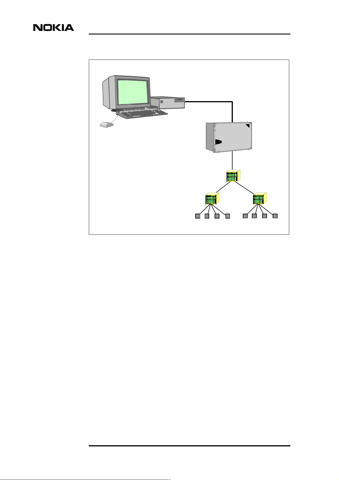
NMS/10 System Frame PC:
- Windows NT Workstation
- NMS/10 System Frame
- Node Managers
NMS/10 MF C2.0
MF Manager C2.5
LAN/WAN
connection
(TCP/IP)
V.11 connection
Figure 1. An example of a management network with NMS/10 System
Frame as the supervising network management system
2.2 General features
MF Manager is an application for configuring NMS/10 MF and PDH Polling,
including the Polling card and Q1 Interface cards, and fault monitoring software,
which poll the managed network.
The main functions of MF Manager are:
• Creating a new configuration with default values
• Modifying an existing configuration, either on-line or off-line
Q1 network elements
• Modifying bus, PDH Manager interface, OS interface and printer spooler
settings
• Configuring filter and alarm classifications of the SNMP interface
• Configuring network test interface
12 (274) © Nokia Networks Oy DN00276927
Nokia Proprietary and Confidential Issue 1-0 en
Page 13

• Editing address, station and device type values
• Starting a network scan and utilizing its results
• Defining performance monitoring jobs
• Defining auto-discovery and utilizing its results
• Starting a fault status consistency check
• Creating filter and alarm classification definitions
• Printing the current configuration.
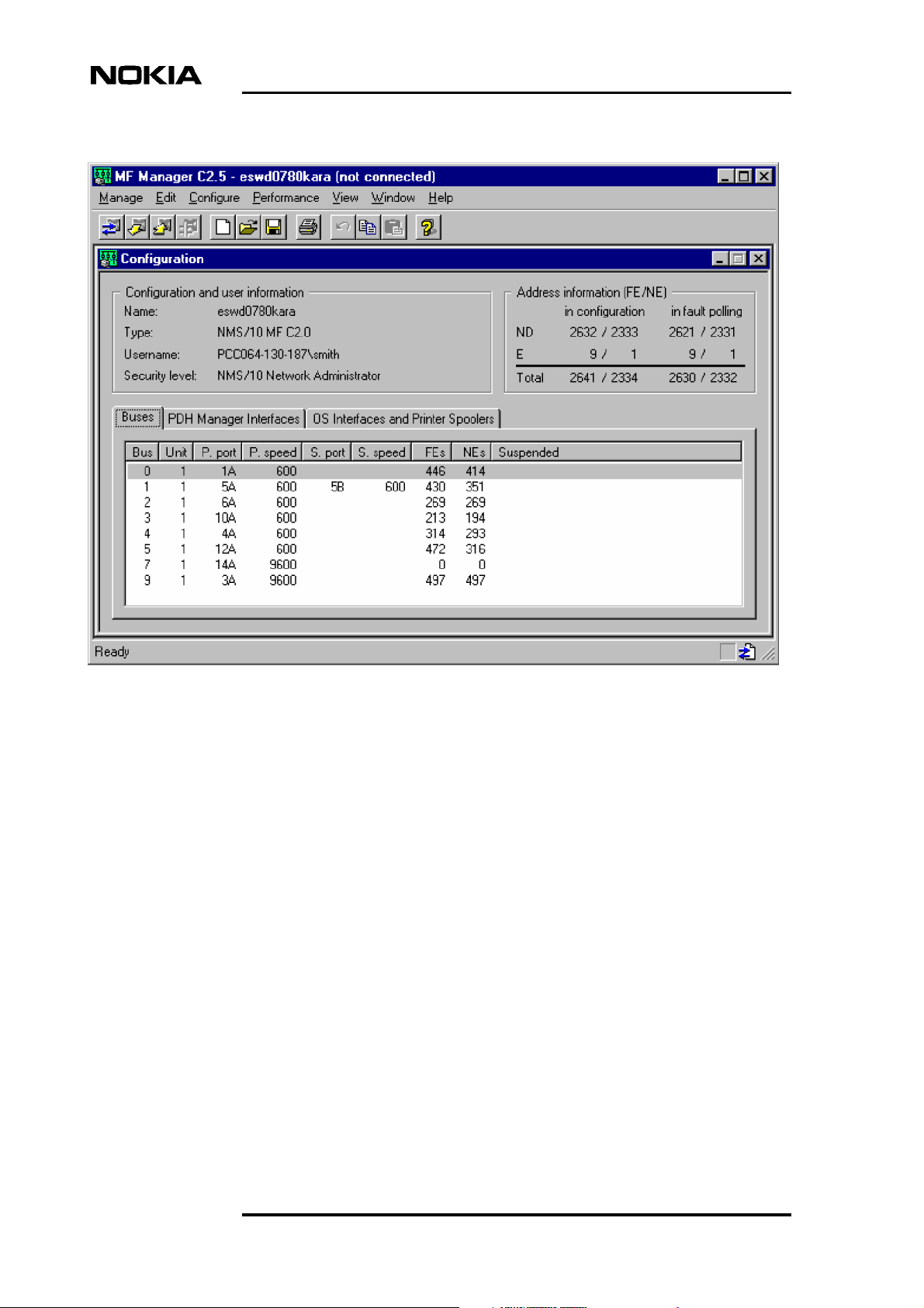
2.3 User interface
MF Manager consists of an application window inside which is the
Configuration window (Figure 2). The user interface complies with the standard
Windows NT controls.
Introduction to MF Manager C2.5
The Configuration window is used for creating a new configuration or changing
an existing configuration. It contains a common part and three tabs for viewing
and editing configurations. The common part contains information about the
current configuration. Below is a brief introduction to the three tabs:
• Buses tab contains bus number, polling unit number, primary polling
direction port and speed, secondary polling direction port and speed (if the
bus is protected) for a bus, and the number of FEs and NEs configured on
the bus. Moreover, information about the suspension of the bus is shown.
• PDH Manager Interfaces tab contains all the PDH manager interfaces in
the current configuration. The list box contains PDH manager interface
number, TCP/IP port and filter and alarm classification names.
• OS Interfaces and Printer Spoolers tab contains all theOS interfaces and
printer spoolers in the current configuration. The OS Interfaces list box
contains OS interface number, command port, alarm port, filter and alarm
classification names. The Printer Spoolers list box contains the printer
spooler number and printer spooler name defined in Windows NT, and
filter and alarm classification names.
DN00276927 © Nokia Networks Oy 13 (274)
Issue 1-0 en Nokia Proprietary and Confidential
Page 14
MF Manager C2.5
Figure 2. The user interface of MF Manager
2.4 System requirements
This section describes the hardware and software requirements of the computer
for running MF Manager C2.5.
MF Manager
• Microsoft Windows NT Workstation or Server version 4.0 with Service
Pack 5 (or later), or
Microsoft Windows NT Server 4.0, Terminal Server Edition with Service
Pack 5 (or later).
• Personal computer with Pentium-compatible processor or faster
• Minimum of 32 megabytes (MB) of RAM (64 MB recommended)
14 (274) © Nokia Networks Oy DN00276927
Nokia Proprietary and Confidential Issue 1-0 en
Page 15

• 5 MB of hard disk space and 1 MB per each saved configuration
• CD-ROM drive for software installation
• SVGA-compatible (800x600) or better graphical colour display. A 17" or
larger monitor is recommended.
• Mouse, trackball or equivalent pointing device
- mouse port and driver software
• Network interface card utilising TCP/IP protocol for communicating with
NMS/10 MF.
• NMS/10 MF or PDH Polling to be configured is successfully installed and
commissioned.
2.5 Compatibility
Introduction to MF Manager C2.5
MF Manager C2.5 is compatible with:
• Windows NT Workstation 4.0 with Service Pack 5 or later
• Windows NT Server 4.0 with Service Pack 5 or later
• Microsoft Windows NT Server 4.0, Terminal Server Edition with Service
Pack 5 (or later)
• NMS/10 MF C2.0
• NMS/10 MF C1.0
• PDH Polling HW C1.0
• PDH Polling SW C1.0 and C2.0.
2.6 Product codes
MF Manager
P31757.01 MF Manager C2.5 (media + licence for 1 system)
P31757.02 MF Manager C2.5 (media + licence for 5 systems)
P31757.03 MF Manager C2.5 (media + licence for 10 systems)
P31757.51 MF Manager C2.5 (software upgrade for 1 system)
P31757.52 MF Manager C2.5 (software upgrade for 5 systems)
DN00276927 © Nokia Networks Oy 15 (274)
Issue 1-0 en Nokia Proprietary and Confidential
Page 16

P31757.53 MF Manager C2.5 (software upgrade for 10 systems).
Manuals
C33846.22 MF Manager C2.5 User's Manual.
2.7 Copyright notice
The copyright to the MF Manager software is owned by Nokia Networks Oy. All
rights reserved. Unauthorized use, copying and modification of this software is
prohibited.
©COPYRIGHT Nokia Networks Oy 2000. All rights reserved.
MF Manager C2.5
16 (274) © Nokia Networks Oy DN00276927
Nokia Proprietary and Confidential Issue 1-0 en
Page 17

3 Installation
This chapter describes the hardware and software installation procedures for MF
Manager C2.5. It covers the following topics:
• Introduction (Section 3.1)
• Installation (Section 3.2).
This chapter assumes that:
• You have the NMS/10 SR CD-ROM.
Installation
• The computerin which you are installing MF Manager fulfils the hardware
• Microsoft Windows NT has been previously installed and it is running
• Any previous version of MF Manager has been uninstalled.
• You know how to use Microsoft Windows NT.
3.1 General
The MF Manager software is supplied with a Setup program, which creates the
necessary directories for MF Manager and then copies the program files to the
directories.
When installing MF Manager, a 30-day trial licence is issued for your use. Refer
to Chapter 4, ’Authorising the licence’ for details on acquiring a permanent
licence.
and software requirements, as detailed in Section 2.4, ’System
Requirements’.
properly.
DN00276927 © Nokia Networks Oy 17 (274)
Issue 1-0 en Nokia Proprietary and Confidential
Page 18
3.2 Installing software
Note
To be able to install MF Manager, you need to log on Windows NT with
administrator rights. If you wish to use domain groups, you must log on with
adequate privileges for the domain controller.
To install MF Manager:
1. Log on Windows NT as an administrator. Close all other applications
before installing MF Manager.
2. To run the Setup program (only follow option a or b):
MF Manager C2.5
a. If you are installing on Windows NT Workstation or Server, insert
the NMS/10 SR CD-ROM inthe drive (e.g.D:). After a fewseconds,
autoplay starts the Setup.
If your computer does not support autoplay, follow the bulleted
instructions below:
- Select Run... from the Start menu.
- Enter D:\autorun.exe (if D: is the CD-ROM drive letter) in
the Open: field and click on OK.
b. If you are installing on Windows NT Server 4.0 Terminal Server
Edition, start the installation with the Add/Remove Programs inthe
Control Panel, and click Install.... Follow the instructions given in
the dialog box, selecting D:\auto run.exe (if D: is the CD-ROM
drive letter) as the install file. After installation TSE will be back in
the Execute mode.
3. You must accept the terms and conditions of the Software Licence to
continue. Click I accept to display the installation main window.
4. The NMS/10 System Release installation main menu is displayed. Click
MF Manager C2.5.
5. Click Install Product to start the installation of MF Manager.
6. The File Download dialog box is displayed. Select Run this program
from its current location and click OK.
7. The Security Warning dialog box is displayed. Click Yes to continue.
18 (274) © Nokia Networks Oy DN00276927
Nokia Proprietary and Confidential Issue 1-0 en
Page 19
Installation
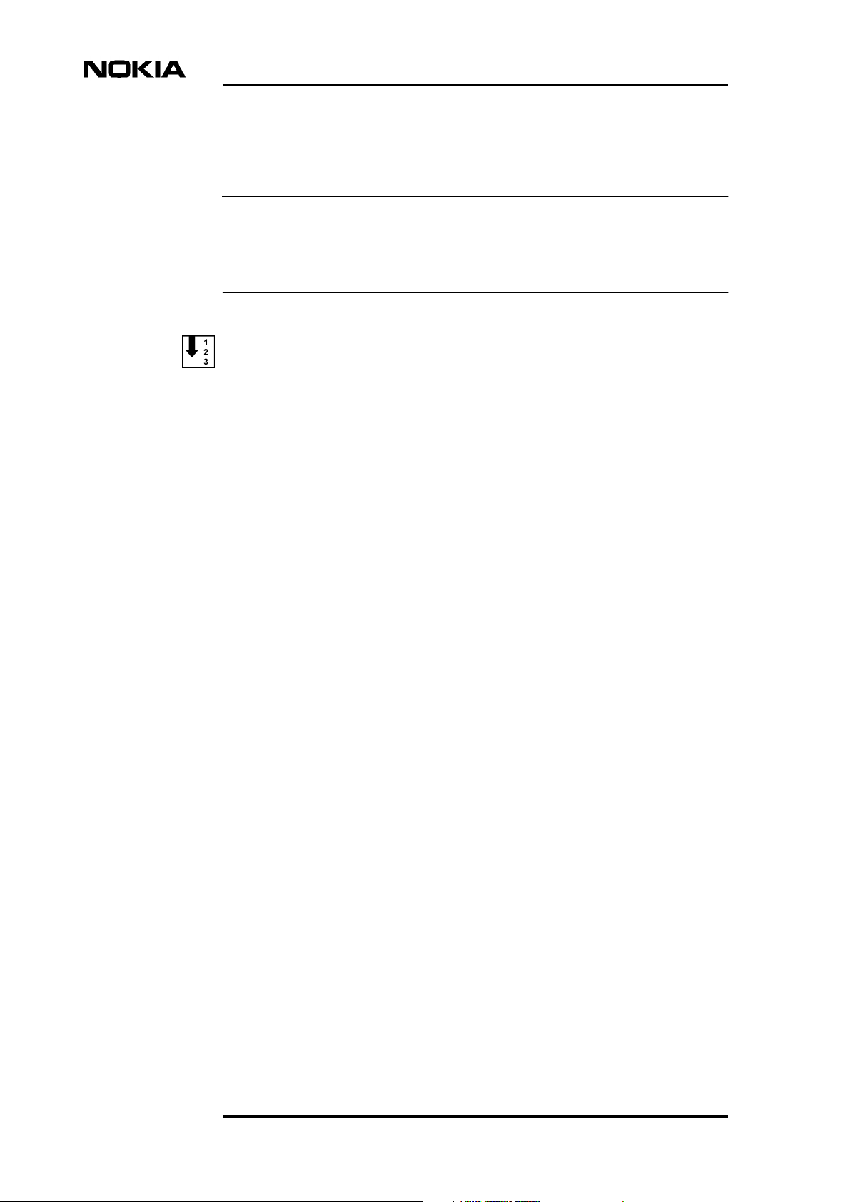
8. After initialization, the Welcome dialog box (Figure 3) appears to indicate
the start-up of the installation program.
Figure 3. MF Manager installation, Welcome dialog box
There are usually three buttons in the installation dialog boxes:
- Next> continues to the next step of installation procedure
- <Back returns to the previous step of installation procedure
- Cancel aborts the installation.
Click the Next> button to proceed with the installation.
9. The Software License Agreement dialog box appears. Read the
agreement.
Click Yes if you accept the agreement and wish to continue with the
installation.
If you do not accept the agreement, click No to quit the installation.
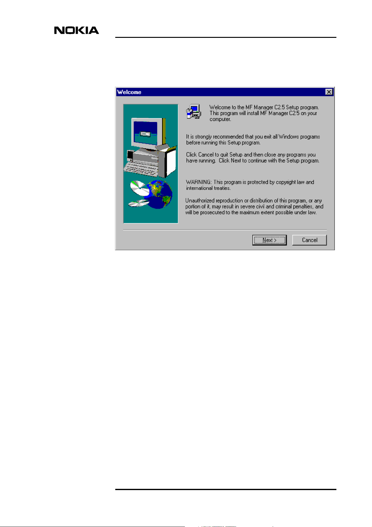
10. Depending on the following conditions, MF Manager can be installed in
different folders:
DN00276927 © Nokia Networks Oy 19 (274)
Issue 1-0 en Nokia Proprietary and Confidential
Page 20
MF Manager C2.5
If NMS/10 MF C2.0 is installed on the same computer, Setup asks if you
wish to install MF Manager in the NMS/10 MF directory hierarchy.
If theenvironment variable NOKIAMGR is already defined on the system,
MF Manager will be installed in that folder.
If theenvironment variable NOKIAMGR is not defined on thesystem, and
there is a MF Manager licence file in the folder C:\NOKIAMGR\MFM,
MF Manager will be installed in this folder.
Otherwise, the Choose Destination Location dialog box is displayed
(Figure 4). Select one of the provided options, or if you want to install the
files elsewhere, select Other folder.
Click the Next> button to proceed with the installation.
If you selected Other folder, click the Browse... button in the Choose
Destination Location (continued) dialog box and select another folder, or
replace the default folder by typing in a new one.
Figure 4. Choose Destination Location dialog box
11. The Select Program Folder dialog box appears. In thisdialog box you can
name the program group to which the MF Manager software icons will be
located.
20 (274) © Nokia Networks Oy DN00276927
Nokia Proprietary and Confidential Issue 1-0 en
Page 21

Installation
Click the Next> button to proceed with the installation.
12. The Start Copying Files appears and showsyou thecurrent settings forthe
installation.
If you accept the settings, click the Next> button to proceed with the
installation. Otherwise click Cancel to abort the installation or <Back to
return to change the settings.
In addition to MF Manager, the following programs are installed:
- TMC-MF Converter
- Network Test Client
- NMS/10 Licence Manager.
13. After copying the files to hard disk, the licence system is activated, NMS/
10 security groups are created, and the file and directory permissions are
set.
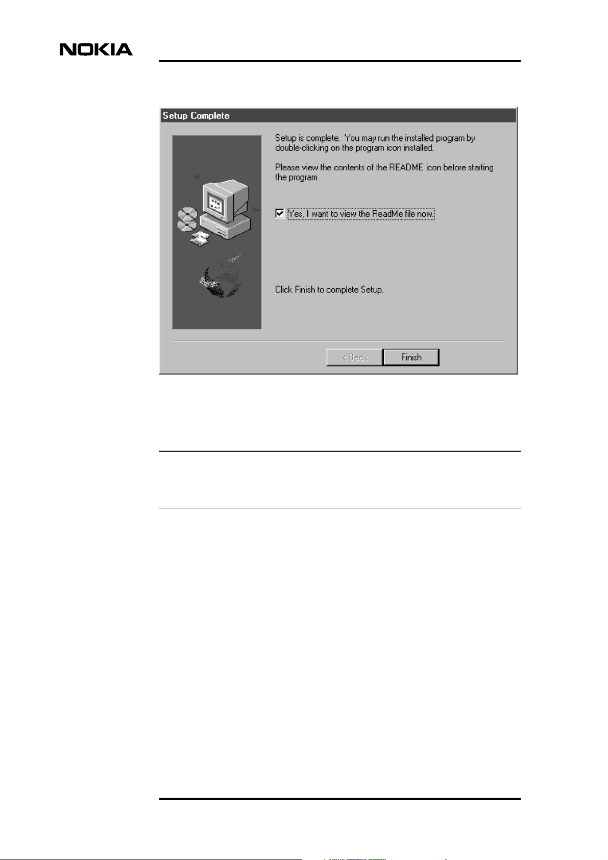
14. The Setup Complete dialog box appears (Figure 5).If you wish to read the
README file, check the corresponding check box.
Click the Finish button to complete the installation and setup.
DN00276927 © Nokia Networks Oy 21 (274)
Issue 1-0 en Nokia Proprietary and Confidential
Page 22
MF Manager C2.5
Figure 5. Setup Complete dialog box
Note
A 30-day trial licence is issued for your use during the installation. Refer to
Chapter 4, ’Authorising the licence’ for details on the Licence Manager.
Refer to Chapter 5, ’Getting Started’ for starting and configuring
MF Manager.
For more information about using NMS/10, please refer to the NMS/10
System Release User Manual.
22 (274) © Nokia Networks Oy DN00276927
Nokia Proprietary and Confidential Issue 1-0 en
Page 23
4 Authorising the licence
This chapter describes how to authorise the MF Manager licences, and assumes
that:
• MF Manager is installed on your computer.
• You are entitled to a licence for this installation. The number of licences
available depends upon the product code for the package you have
purchased.
Authorising the licence
Caution
Moving the PC clock backwards disables any existing licences.
4.1 Software licence validation
The licence verification system used by Nokia is a software licence based on a
Site Code generated forthe computerand aSite Keyprovided by NokiaCustomer
Services.
NMS/10-related products are protected by software controlled licensing system.
Before you can use NMS/10 System Frame or other licence-protected
applications like MF Manager, you must have a licence for your installation.
You are granted an automatic 30-day trial licence when starting up MF Manager
for the first time. Note that for each release, this trial licence can be granted only
once on a single PC. Thus, if you reinstall the software after the trial licence
expires, a new trial licence will not be granted. In order to set the system up for
permanent operationyou need to purchase a corresponding software licence from
Nokia to get a Site Key installed on your system.
The NMS/10 Licence Manager program is a tool to help the customers of Nokia
to manage licensing of NMS/10 related applications.
When you run Licence Manager on the computer on which you have installed the
software, a Site Code will be generated automatically. Nokia Customer Services
will supply you with a Site Key that matches this Site Code.
DN00276927 © Nokia Networks Oy 23 (274)
Issue 1-0 en Nokia Proprietary and Confidential
Page 24
MF Manager C2.5
Caution
The software licence is based on the machine and disk configuration and will be
lost if a disk is replaced or reformatted. If you have a disk failure, you will need
to contact Nokia Customer Services to get a new Site Key for your restored
software.
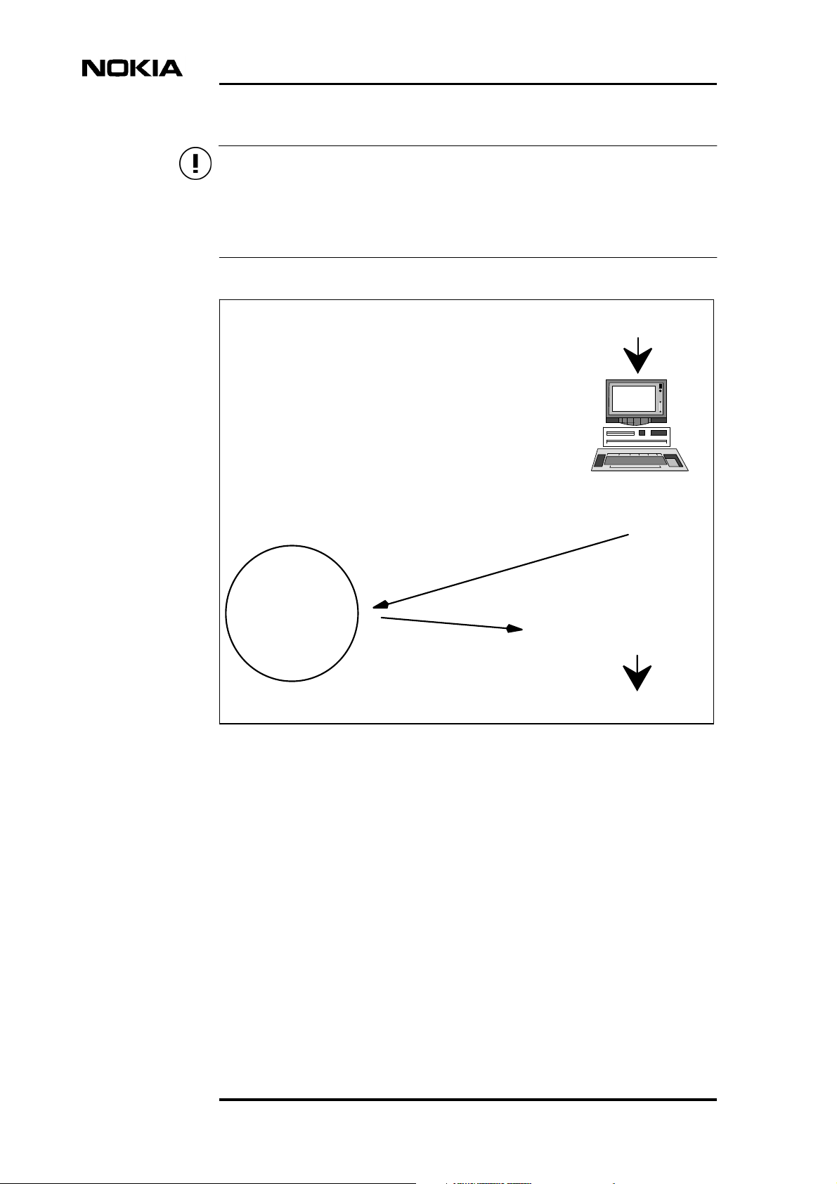
1.
Install Software
3.
Supply Site Code
and purchase details
to Nokia Customer
Services
Nokia
Customer
Services
Figure 6. Software licence sequence
2.
Generate
Site Code
Enter Site Key for
4.
Licence Manager
Use Software
5.
24 (274) © Nokia Networks Oy DN00276927
Nokia Proprietary and Confidential Issue 1-0 en
Page 25
4.2 Authorising a new licence
To authorise a new licence follow the steps below:
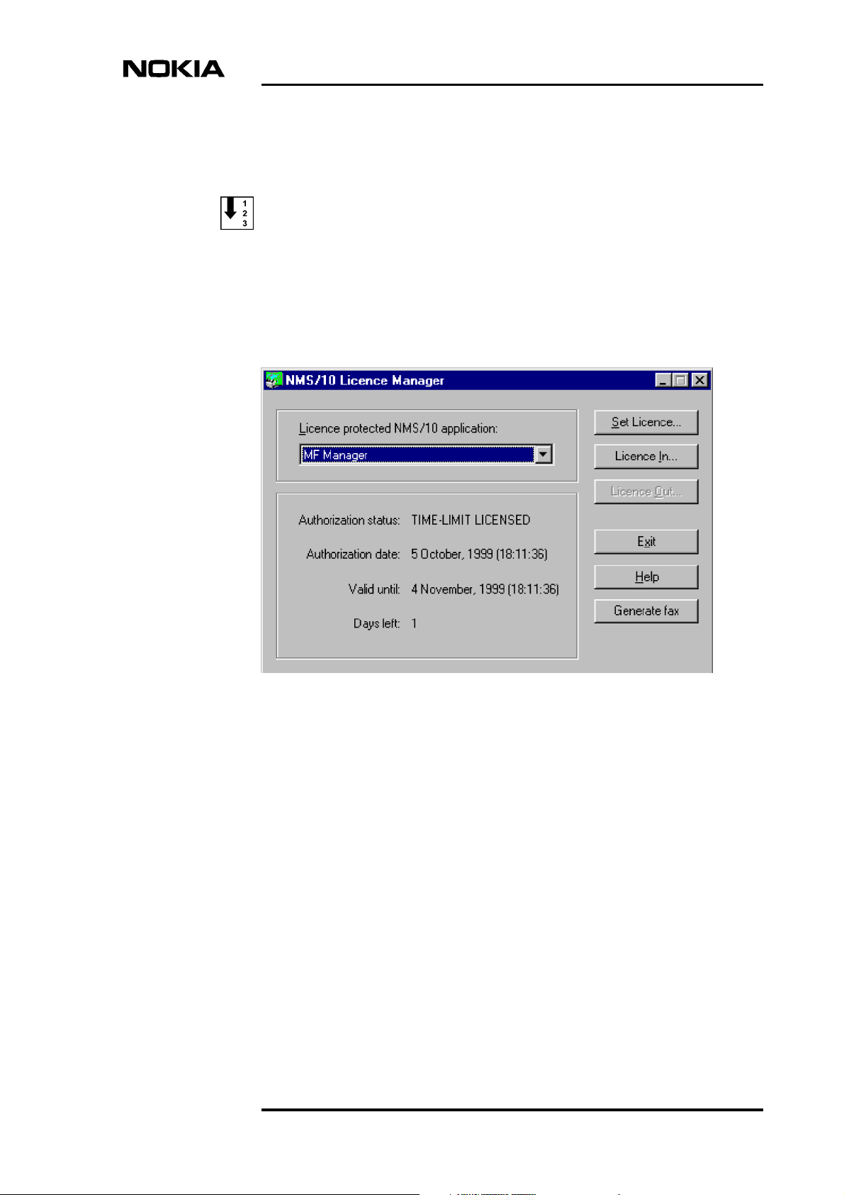
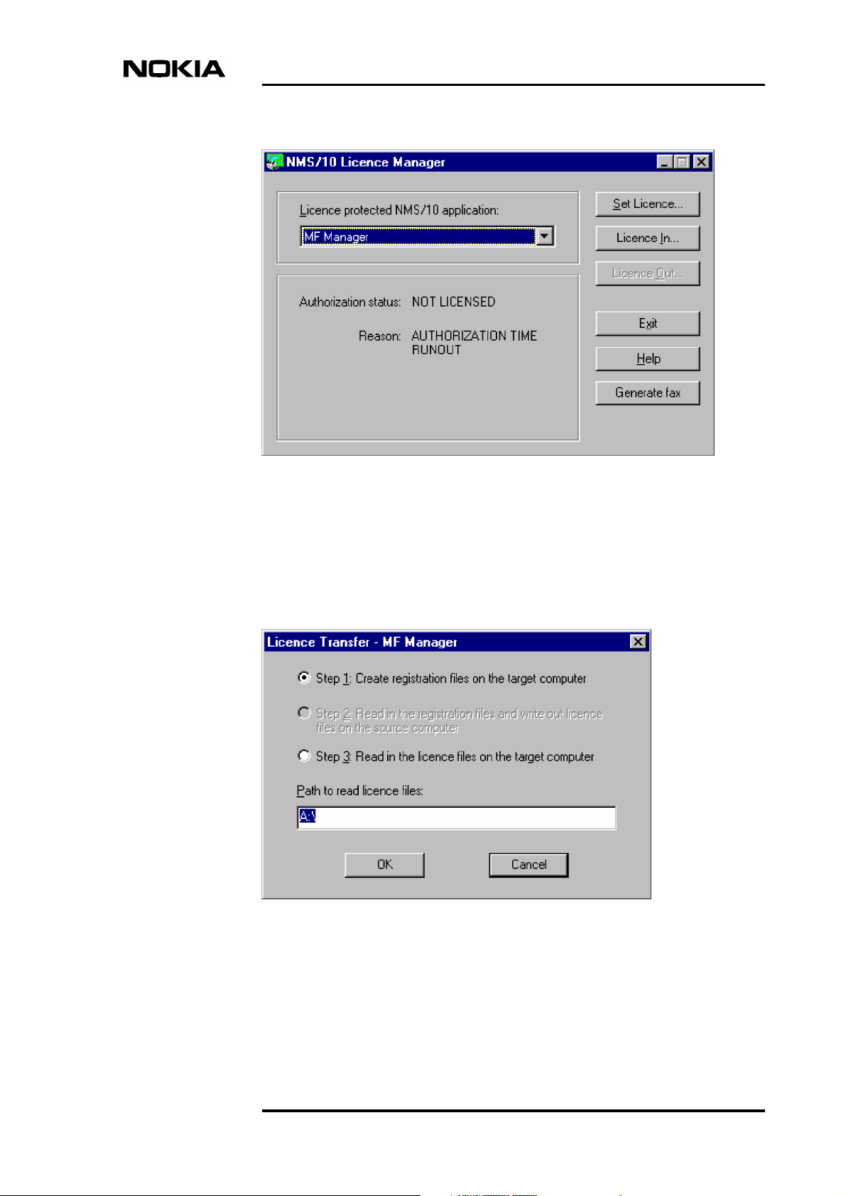
1. Start the Licence Manager from the Windows NT Start menu ( Programs
→ MF Manager → NMS10 Licence Manager). The NMS/10 Licence
Manager dialog box is displayed with the current licence status of NMS/
10 SR products.
Authorising the licence
Figure 7. NMS/10 Licence Manager dialog box (time-limit licence)
2. Select MF Manager.
3. Click onGenerate fax.A dialog box for preparing the fax is displayed.Fill
in your contact information, the licenced product serial number and the
number of copies you request (1, 5, or 10).
4. Click OK. This prints the Authorisation Request fax sheet, including the
newly generated Site Code (a unique number for the PC installation).
5. Send the fax and a copy of your original Licence Agreement to Nokia
Customer Services.
6. Nokia Customer Services supplies a site key code.
DN00276927 © Nokia Networks Oy 25 (274)
Issue 1-0 en Nokia Proprietary and Confidential
Page 26
MF Manager C2.5
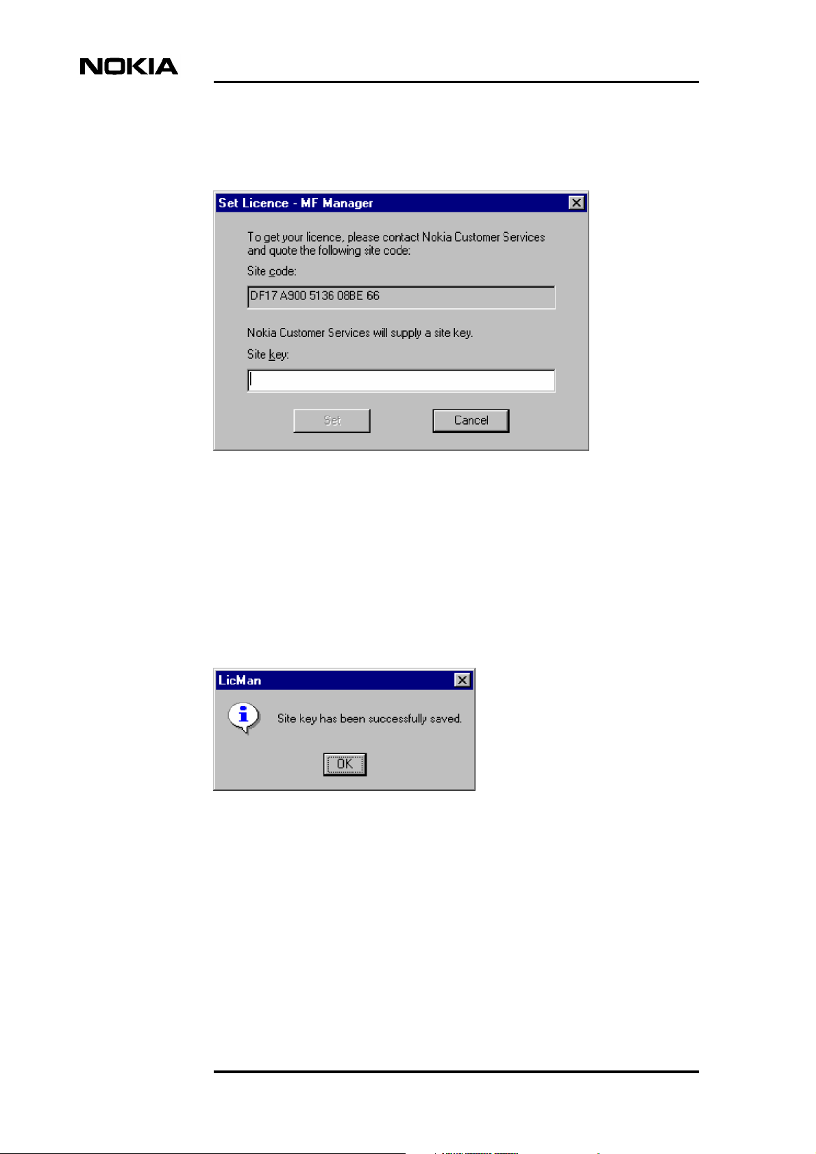
7. In the Licence Manager, select MF Manager and click Set Licence.... The
Set Licence dialog box is displayed.
Figure 8. Set Licence dialog box
8. Enter the code supplied to you in the Site key: edit field.
9. Click Set.
10. If the validation is successful, the confirmation message shown in Figure 9
is displayed.
Figure 9. Licence confirmation message
26 (274) © Nokia Networks Oy DN00276927
Nokia Proprietary and Confidential Issue 1-0 en
Page 27

4.3 Upgrading a trial licence
If you have a trial licence, you can upgrade it to a permanent software
licence by following the steps below:
1. The software and trial licence must already be installed in the target
machine.
2. Order a full software licence from your Nokia Account Manager.
3. Follow the same steps as in section 4.2.
4.4 Transferring a licence
Authorising the licence
It is not necessary to contact Nokia Customer Services if you wish to move your
licensed software from one PC to another. The Licence Manager software can
transfer the software licence between the two PC's.
The sequence below assumes that you will be using a floppy disk to hold the
registration and licence information. If both PC's are connected to a LAN and
have access to a shared directory, you could also use the path to the directory as
the location of the registration and licence imprint files.
DN00276927 © Nokia Networks Oy 27 (274)
Issue 1-0 en Nokia Proprietary and Confidential
Page 28
Source Computer
(PC with Licence)
Install Software
1.
(to new PC)
Target Computer
Create Registration
2.
Imprint File on Disk
MF Manager C2.5
Write Licence
3.
Imprint File to
Disk
5.
Figure 10. Software licence sequence
To transfer the licence, follow the steps below:
1. Install the software in the target computer.
Read Licence
4.
Imprint File
from Disk
Use Software
2. Insert a blank floppy disk in the target computer and run Licence Manager.
28 (274) © Nokia Networks Oy DN00276927
Nokia Proprietary and Confidential Issue 1-0 en
Page 29
Authorising the licence
Figure 11. NMS/10 Licence Manager dialog box (no licence)
3. Select MF Manager.
4. Select Licence In.... The Licence Transfer dialog box is displayed.
Figure 12. Licence Transfer dialog box (Step 1)
DN00276927 © Nokia Networks Oy 29 (274)
Issue 1-0 en Nokia Proprietary and Confidential
Page 30
MF Manager C2.5
5. Enter a path. Usually you will need to enter only A:\ in order to transfer the
licence to a floppy disk.
6. Click on OK.
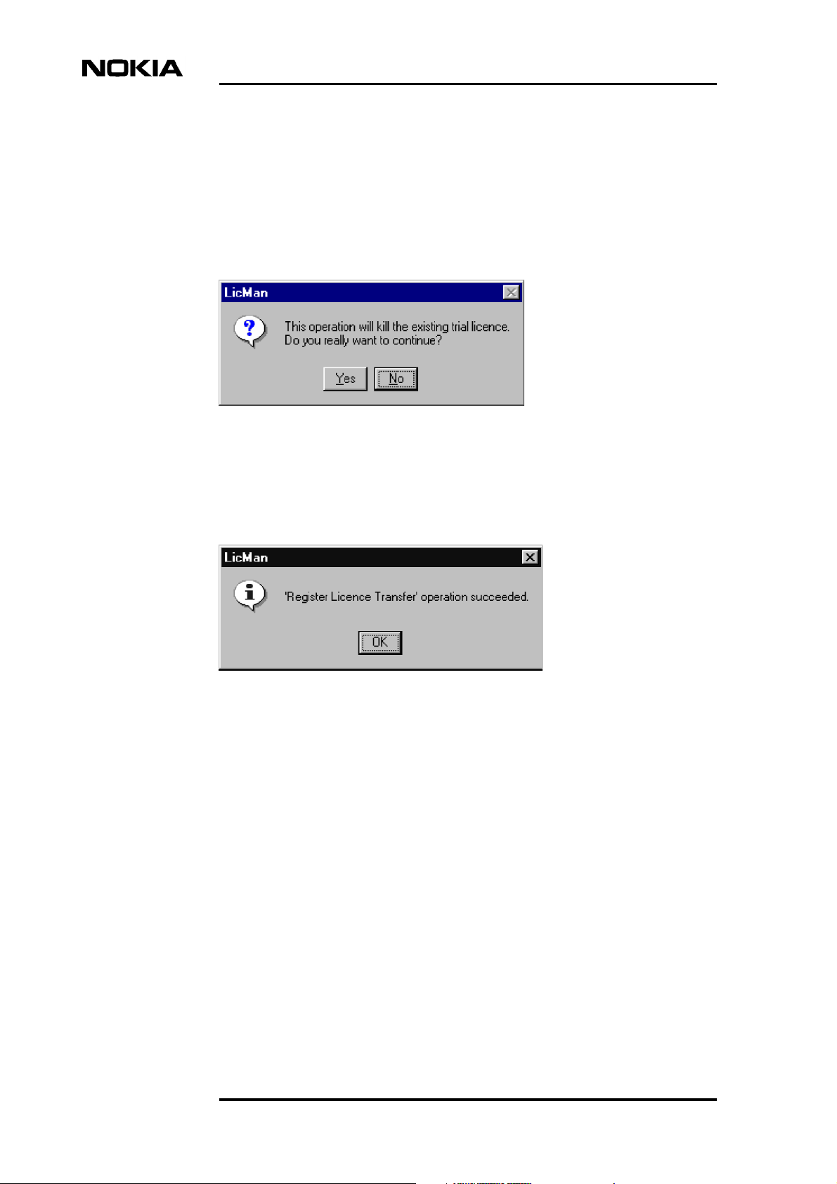
Unless your copyof NMS/10was unlicensed,the messageshown inFigure
13 is displayed to warn you that the previous trial licence will be cancelled.
Figure 13. Kill licence warning message
7. Select Yes.
Figure 14. Licence transfer succeeded message
8. Move the disk to the source computer which has the existing licence and
run Licence Manager. The NMS/10 Licence Manager dialog box is redisplayed as shown in Figure 15.
30 (274) © Nokia Networks Oy DN00276927
Nokia Proprietary and Confidential Issue 1-0 en
Page 31

Authorising the licence
Figure 15. NMS/10 Licence Manager dialog box (licenced)
9. Select MF Manager.
10. Select Licence Out....
Figure 16. Licence Transfer dialog box (Step 2)
11. Enter the correct path if drive A: is not the location of the directory.
DN00276927 © Nokia Networks Oy 31 (274)
Issue 1-0 en Nokia Proprietary and Confidential
Page 32

MF Manager C2.5
12. Select OK.
Figure 17. Transfer Out operation succeeded message
13. Move the disk (which now contains the licence)back to the target computer
which was used to create the registration imprint file. (The disk containing
the licence will not transfer the licence to any other computer.)
Caution
After you have read the registration file and written the licence imprint file (Step
3 in Figure 10), the source machine no longer has a licence. The only way to
continue usingthe software is totransfer the licence tothe target computer. If you
decide to keep the licence on the source computer after you have written the
licence imprint file, you will have to complete the transfer to the target computer
and then repeat the transfer process to return the licence to the original machine.
Do not lose or damage the disk containing the licence imprint file before the
licence transfer is completed since the original licence now resides on the disk.
14. Run Licence Manager again on the target computer.
32 (274) © Nokia Networks Oy DN00276927
Nokia Proprietary and Confidential Issue 1-0 en
Page 33

Authorising the licence
Figure 18. NMS/10 Licence Manager dialog box (no licence)
15. Select MF Manager.
16. Select Licence In....
17. If drive A: is not the location of the file, enter the path and directory
containing the file.
18. Click on OK.
DN00276927 © Nokia Networks Oy 33 (274)
Issue 1-0 en Nokia Proprietary and Confidential
Page 34

Figure 19. Licence Transfer dialog box (Step 3)
MF Manager C2.5
19. The licence is transferred from the disk to the target PC.
20. Run the software on the target computer. The source computer will still
have the software installed, but its licence is invalid.
Figure 20. Licence Transfer succeeded message
34 (274) © Nokia Networks Oy DN00276927
Nokia Proprietary and Confidential Issue 1-0 en
Page 35

5 Getting started
This chapter explains the basic principles of operation of MF Manager. It covers
the following topics:
• Security (Section 5.1)
• Starting MF Manager (Section 5.2)
• Working with NMS/10 MF configurations (Section 5.3)
• Configuring NMS/10 MF and PDH Polling (Section 5.4)
Getting started
• Using online help (Section 5.5)
• Printing (Section 5.6)
• Making backups (Section 5.7)
• Restoring backups (Section 5.8)
• Exiting MF Manager (Section 5.9).
This chapter assumes that:
• The MF Manager program has been installed in your computer as
• A licence has been authorised as described in Chapter 4.
• There is a network connection available between the computer with MF
For information about operating NMS/10, refer to the NMS/10 System Release
User Manual.
5.1 Security
described in Chapter 3.
Manager and NMS/10 MF.
For additional information on user groups and shares createdby MF Manager and
NMS/10 MF installation programs, refer to Appendix A.2.
DN00276927 © Nokia Networks Oy 35 (274)
Issue 1-0 en Nokia Proprietary and Confidential
Page 36

MF Manager C2.5
The NMS/10 security model defines five user groups that are used as security
levels. The user groups, sorted in ascending order by the security level, are:
• NMS/10 Operator
• NMS/10 Basic
• NMS/10 Experienced
• NMS/10 Network Administrator
• NT Administrator.
The NT Administrator group is a combination of two predefined Windows NT
user groups: Domain Administrator and Local Administrator.
If you do not belong to any of the user groups, MF Manager displays an error
message and does not start. If you belong to multiple user groups, the most
powerful user group defines the security level.
Note
MF Manager installation program creates the first four user groups. You (or the
administrator) must add your username to one of the security groups. You must
belong in the security group both on the local computer and on the NMS/10 MF
computer.
Initially all restrictions are enforced according to user security level on the local
computer. When MF Manager connects to an NMS/10 MF C2.0, it re-checks to
which securitygroup you belong on that computer. If it is lower, that will be used.
In some cases, e.g. you do not belong in any of these groups on the system, you
are not allowed to do anything on that computer.
The section below describes the operations allowed on each security level (the
next level always includes all the allowed operations on the previous levels):
NMS/10 Operator
Can create a newconfiguration or openan existinglocal configuration, butcannot
save changes. Save or Save As... commands only validate the configuration.
NMS/10 Basic
Can connect to the NMS/10 MF, but cannot send changes
Note
Configuration files are overwritten on the local PC.
36 (274) © Nokia Networks Oy DN00276927
Nokia Proprietary and Confidential Issue 1-0 en
Page 37

Getting started
Can work with network scan and auto-discovery log files that are on the local PC,
but cannot remove the log files or anything from them. Can save the
configuration. Can view the date, time, timezone, and daylight saving settings on
the NMS/10 MF workstation, but cannot change them. Can view the status of the
NMS/10 MF processes and make queries about current users on the selected
system.
NMS/10 Experienced
Can fully work with network scan and auto-discovery log files, both local and
remote. Can send the configuration.
NMS/10 Network Administrator
Can fully use MF Manager: define fault status consistency checks and network
scans; set the date, time, timezone, and daylight saving settings on the NMS/10
MF workstation; stop, start, and restart NMS/10 MF processes and restart the
NMS/10 MF workstation.
NT Administrator
Can manage WindowsNT access rights, for example, define users' security levels
using the NMS/10 user groups. This is done using Windows NT's own security
features and tools.
5.2 Starting MF Manager
To start MF Manager:
1. Log on Microsoft Windows NT.
2. Select the MF Manager item found from the Windows NT 4.0 Start →
Programs → MF Manager menu.
An emptymain window titled MF Manager C2.5 is displayed (Figure 21).
DN00276927 © Nokia Networks Oy 37 (274)
Issue 1-0 en Nokia Proprietary and Confidential
Page 38

MF Manager C2.5
Figure 21. MF Manager starting window
5.3 Working with configurations
MF Managerhas two kinds of configurations: anoff-line configuration and an online configuration.
An off-line configuration is opened with Manage → Open..., or created with
Manage → New.... With an off-line configuration, you are working with a
configuration on thelocal PC.A connectionto theNMS/10 MF is not needed, and
hence off-line configurations can be created in advance to be utilised later. The
configuration is not necessarily up-to-date. A new configuration is always offline at the beginning.
An on-line configuration is opened with Manage → Connect.... With an on-line
configuration, you are working with the configuration on the NMS/10 MF. There
is a connection to the NMS/10 MF and the up-to-date configuration is copied
from there.
38 (274) © Nokia Networks Oy DN00276927
Nokia Proprietary and Confidential Issue 1-0 en
Page 39

Getting started
A current configuration is the configuration (off-line or on-line) you are working
with.
Naming configurations
An off-line configuration can have any name, as long as the name is a valid
computer name (existing or non-existing). The length of the name can be 15
characters.
An on-line configuration name is always the same as the computer name of the
NMS/10 MF or PDH Polling workstation.
Sending configurations
You can send the current configuration to NMS/10 MF or PDH Polling with the
command Manage → Send. Ifyou areworking withan on-lineconfiguration, the
configuration is activated immediately. If the configuration is off-line, the
configuration is activated in the next restart of NMS/10 MF or PDH Polling.
Note
The off-line configuration name must be the same as the computer name of NMS/
10 MF. Use Manage → Save As... if necessary.
Note
MF Manager restarts the NMS/10 MF automatically when an off-line
configuration is sent.
You cannot use Manage → Send if:
• there is no Configuration window or it is iconized
• the user level is lower than NMS/10 Experienced
• configuration is a new configuration, i.e. it has no name
• connection to NMS/10 MF is open, but there are no changes in the
configuration.
Connection to NMS/10 MF
When connecting to NMS/10 MF or PDH Polling with MF Manager, you must
have adequate user rights on the target workstation.
For more information, refer to Appendix A, ’Connecting Nokia Managers to
NMS/10 MF or PDH Polling workstation’.
DN00276927 © Nokia Networks Oy 39 (274)
Issue 1-0 en Nokia Proprietary and Confidential
Page 40

MF Manager C2.5
Configuration types
NMS/10 MF C2.0
This configuration contains buses, PDH Manager Interfaces, OS Interfaces,
Printer Spoolers, SNMP Interface, and Network Test Interface. You can also
define the performance monitoring.
There are one polling unit and two Q1 Interface unitsinstalled in an industrial PC.
Configuration can contain up to 16 buses.
Note
PDH Manager Interface does not contain FM information.
NMS/10 MF C1.0
This configuration contains buses, PDH Manager Interfaces, OS Interfaces, and
Printer Spoolers. You can also define the performance monitoring.
There are one polling unit and two Q1 Interface unitsinstalled in an industrial PC.
Configuration can contain up to 16 buses.
Note
This configuration type was PDH Polling and OS Interface in MF Manager C2.0.
PDH Polling C2.0
This configuration contains buses and PDH Manager Interfaces. User can also
define the performance monitoring.
There are one polling unit and one Q1 Interface unit installed in a desktop PC.
Configuration can contain up to 8 buses.
Note
This configuration type was PDH Polling and PM Poller in MF Manager C2.0.
PDH Polling C1.0
This configuration contains buses and PDH Manager Interfaces.
40 (274) © Nokia Networks Oy DN00276927
Nokia Proprietary and Confidential Issue 1-0 en
Page 41

Getting started
There is one polling unit and one Q1 Interface unit installed in a desktop PC.
Configuration can contain up to 8 buses.
Note
This configuration type was PDH Polling in MF Manager C2.0.
Interfaces
PDH Manager interface
These interfaces are used by PDH Alarm Manager and node managers.
OS interface
This interface is used by NMS/100(0).
Printer spooler
This interface is used for printing out alarms.
SNMP interface
This interface is used for sending alarm information via SNMP.
Network Test interface
The Network Test client runs tests through this interface.
5.3.1 Creating a new configuration (off-line)
The following steps are required to enable MF Manager to work properly with
NMS/10 MF or PDH Polling. For details on configuration types, refer to section
6.22, ’Configuration window’.
Note
You must at least give an equipment ID for a new configuration before you can
save or send it. For the configuration type NMS/10 MF C2.0 also the logon
domain of Network Test Interface is required.
DN00276927 © Nokia Networks Oy 41 (274)
Issue 1-0 en Nokia Proprietary and Confidential
Page 42

To create a new configuration:
1. Choose the menu command Manage → New. Select the configuration type
in the Configuration Type dialog box and click OK.
Select the configuration type according to Table 2, depending on which
configuration you wish to start.
Table 2. Configuration types of MF Manager
Configuration type Equipment
NMS/10 MF C2.0 NMS/10 MF C2.0
NMS/10 MF C1.0 NMS/10 MF C1.0
PDH Polling C2.0 PDH Polling Functionality C2.0
MF Manager C2.5
PDH Polling C1.0 PDH Polling Functionality C1.0
2. A new configuration with default values will be opened in the
Configuration window.
3. Give an equipment ID for the configuration by choosing Configure →
PDH Polling General... and filling in the Equipment ID in the
Equipment ID tab of the PDH Polling General dialog box.
If you selected NMS/10 MF C2.0 as the configuration type, define the
logon domain in the Network Test Interface dialog box by choosing
Configure → Network Test Interface....
4. Add a bus to the configuration:
Click on the Buses tab to make it active.
Choose Configure → Bus → Add.... The Add Bus dialog box is
displayed.
Select a bus number (0...240) from the list and click OK. The Bus x dialog
box is displayed.
You can either configure the bus or accept the default values. In either case
you must select theport in thePort tab. Referto Section6.12, ’Bus xdialog
box’ for details on configuring buses. Click OK when you have completed
configuring the bus.
5. Define network addresses for the bus:
42 (274) © Nokia Networks Oy DN00276927
Nokia Proprietary and Confidential Issue 1-0 en
Page 43

Click the Buses tab to make it active.
Choose Configure → Bus → Addresses... or click Edit... in the Bus x
dialog box. The Addresses dialog box is displayed.
See Section 6.8, ’Addresses dialog box’ for details on defining addresses
for buses. Click OK when you have completed defining addresses.
6. Define PDH manager interface:
Click the PDH Manager Interfaces tab to make it active.
Choose Configure PDH Manager Interface Add.... The PDH Manager
Interface dialog box is displayed.
Define the logon domain in the Port tab.
See Section 6.41, ’PDH Manager Interface x dialog box’ for details on
changing the configuration of PDH Manager interface. Click OK when
you have completed the configuration.
Getting started
7. Define OS interface:
Click the OS Interfaces and Printer Spoolers tab to make it active.
Choose the menu command Configure → OS Interface → Add.... The
OS Interface dialog box is displayed.
Define the logon domain in the Ports tab.
See Section 6.39,’OS Interface x dialog box’ for details on changing the
configuration of OS interface. Click OK when you have completed the
configuration.
8. Save the new configuration with the command Manage → Save As... and
if you wish to send it to NMS/10 MF or PDH Polling, use the command
Manage → Send.
The name must be the same as the MF computer name.
5.3.2 Changing an existing off-line configuration
To open an existing off-line configuration:
1. Choose the menu command Manage → Open.... The Open dialog box
will be displayed.
DN00276927 © Nokia Networks Oy 43 (274)
Issue 1-0 en Nokia Proprietary and Confidential
Page 44

MF Manager C2.5
2. Select an off-line configuration name in the Name: list box and click OK.
The off-line configuration will be opened in the Configuration window.
To change an opened off-line configuration:
1. Add, modify or delete a bus from the configuration:
Choose one of the menu commands Configure → Bus → Add.../
Modify.../Delete.
See Section 6.10.5, ’Configure menu’ for modifying buses.
2. Define network addresses for the buses:
Choose the menu command Configure → Bus → Addresses.... The
Addresses dialog box will be displayed.
See Section 6.8, ’Addresses dialog box’ for details on defining addresses
for buses. Click OK after completing defining addresses.
3. Save the modified configuration with the command Manage → Save and
if you wish to send it to NMS/10 MF or PDH Polling, use the command
Manage → Send.
5.3.3 Changing an on-line configuration
To select an on-line configuration:
1. Give the menu command Manage → Connect.... The Connect dialog box
will be displayed.
2. Select or type an on-line configurationname in the Name listbox and click
OK. The on-line configuration will be opened in the Configuration
window.
Connection to the NMS/10 MF or PDH Polling remains open until you
disconnect it with the Disconnect command.
To change an on-line configuration:
• Follow the steps in the previous section that describes how to change an
opened off-line configuration.
44 (274) © Nokia Networks Oy DN00276927
Nokia Proprietary and Confidential Issue 1-0 en
Page 45

5.4 Configuring NMS/10 MF and PDH Polling
This section describes the work order and main tasks of configuring NMS/10 MF
and PDH Polling with MF Manager. It covers the following topics:
• Converting TMC configurations (Section 5.4.1)
• General settings (Section 5.4.2)
• Adding buses (Section 5.4.3)
• Adding network elements (Section 5.4.4)
• Configuring the PDH Manager interface (Section 5.4.5)
• Configuring the OS interface (Section 5.4.6)
• Adding alarm printers (Section 5.4.7).
For details on installation and commissioning NMS/10 MF, refer to the NMS/10
MF Operating Manual.
Getting started
The Readme file of MF Manager contains the latest information on MF Manager.
The README.TXT file of NMS/10 MF contains the latest information on NMS/
10 MF and things to take into consideration when it is used with other NMS
systems.
Configuring PDH Polling
Configuring PDH Polling is similar to configuring NMS/10 MF with the
exception that OS Interfaces, PrinterSpoolers, SNMPInterface and NetworkTest
Interface are not available.
For details on installation and commissioning PDH Polling, refer to the PDH
Polling Installation Instructions.
The README.TXT file of PDH Polling contains the latest information on PDH
Polling and things to take into consideration when it is used with other NMS
systems.
5.4.1 Converting TMC configurations
If you wish to use existing TMS4 configurations, use TMC-MF Converter
before making any other configurations with MF Manager.
You can add network elements from TMC (TMS4) configurations with the TMCMF Converter program which is included in the MF Manager installation disks.
DN00276927 © Nokia Networks Oy 45 (274)
Issue 1-0 en Nokia Proprietary and Confidential
Page 46

MF Manager C2.5
To convert TMC configuration into NMS/10 MF or PDH Polling
configuration:
1. In TMS4, write the TMC configuration to a floppy disk. For details, refer
to the TMS4 Operating Manual.
2. Insert the disk in the computer where you have MF Manager and TMC-MF
Converter installed.
3. TMC-MF Converter will not overwrite an existing NMS/10 MF
configuration. If you wish to use an existing name, rename or remove the
old configuration. See Appendix B for details on handling configurations.
4. Start TMC-MF Converter from the Windows NT Start menu (Programs
→ MF Manager → TMCMF Converter).
5. Enter thedestination configurationname (thetarget NMS/10MF computer
name), and click Convert.
6. Start MF Manager and open the created configuration (Manage →
Open...).
To modify the configuration:
1. Fill in all information marked with question marks (?). You may need to
change theconfiguration type from the default NMS/10 MF C1.0 (Manage
→ Special Change → Configuration Type).
2. Set the Q1 Packet time-out value.
Note
Polling parametersare not converted. NMS/10 MF or PDH Polling default values
are used instead.
3. Save the configuration (Manage → Save or Manage → Save As...).
If saving fails, there are inconsistencies in the configuration.
46 (274) © Nokia Networks Oy DN00276927
Nokia Proprietary and Confidential Issue 1-0 en
Page 47

To transfer the configuration to NMS/10 MF or PDH Polling:
1. After you have successfully saved the configuration, send it to the target
NMS/10 MF or PDH Polling (Manage → Send).
2. The target NMS/10 MF or PDH Polling restarts with the new
configuration.
5.4.2 General settings
You can change the general settings of NMS/10 MF and PDH Polling with the
MF Manager command Configure → PDH Polling General.... Make the
following settings:
• set identification number for the system (Equipment ID)
Getting started
• select the FE name format
• define stations
• define equipment types (device types)
• define global filter and alarm classification.
For details, refer to Chapter 6, ’Reference’.
5.4.3 Adding buses
To add buses:
1. Choose Configure → Bus → Add....
2. Define the bus number and physical port.
3. Set the value of Q1 packet time-out according to local network
environment.
At the beginning, we recommend a longer time-out to find out that the
connection to network elements is in order (for example, with bus speed
9600 bit/s, set the Q1 packet time-out to 5 [500 ms], and with bus speed
2400 bit/s, set it to 8 [800 ms]). Later you can optimise the system
performance by decreasing the time-out value.
DN00276927 © Nokia Networks Oy 47 (274)
Issue 1-0 en Nokia Proprietary and Confidential
Page 48

4. Send the configuration to NMS/10 MF or PDH Polling (Manage → Send).
5.4.4 Adding network elements
To do the network scan:
1. Choose Manage → Special → Network Scan....
2. Define buses for the network scan and address ranges for each bus.
3. Click Start. If the address range is large, it will take some time to complete
the scan. A moving magnifying glass is displayed on the status bar during
the scan (if there is a connection).
The network scan is the quickest and most convenient way of creating a network
configuration. Beforescanning the network, youmust add all the necessary buses
and send the configuration to the NMS/10 MF or PDH Polling.
MF Manager C2.5
To check if the network scan is complete:
• A moving magnifying glass is displayed on the status bar during the scan
(if there is a connection).
• Choose View → Network Scan Log....
- If the network scan is in progress, MF Manager displays a message
about it.
- If the network scan is completed, MF Manager displays the network
scan log.
To add network scan results to the configuration:
1. Add the addresses to the configuration.
The FE name may be as is, but you need to define a station and device type.
2. Send the configuration to NMS/10 MF or PDH Polling (Manage → Send).
48 (274) © Nokia Networks Oy DN00276927
Nokia Proprietary and Confidential Issue 1-0 en
Page 49

5.4.5 Configuring the PDH Manager interface
Nokia Node Managers and Alarm Managers use the PDH Manager interface for
connecting to NMS/10 MF and PDH Polling. The user information sent to the
NMS/10 MF or PDH Polling must be valid within the logon user groups when
attempting to log on. On the NMS/10 MF C2.0 you must define the logon group.
Others use the fixed Nokia NMS/10 MF Command Interface user group.
After the installation of NMS/10 MF or PDH Polling, there is one PDH Manager
interface readily configured. Also, the user PAM (with an initial password PAM)
has been created into the Nokia NMS/10 MF Command Interface user group.
Nokia Node Managersmay use the PAM user account for logging invia this PDH
Manager interface. We recommend you to change the password of the user PAM,
or add new users to the Nokia NMS/10 MF Command Interface user group.
If the configuration type is NMS/10 MF C2.0, you can connect to one PDH
Manager Interface from multiple computers. Other configuration types require a
separate PDH Manager Interface for each computer.
Getting started
To configure the PDH Manager interface:
1. Check the current parameters of the PDH Manager interface and make the
necessary changes (Configure → PDH Manager Interface → Modify...).
2. The PDH Manager Interface dialog box is displayed. Modify the fields
in the General tab if necessary and then click on the Port tab.
3. Fill in the fields in the Port tab:
Nokia Node Managers and Alarm Managers must use the TCP/IP port
defined here. Make sure that no other PDH Manager interface uses this
TCP/IP port.
4. Save the configuration and activate it (Manage → Send) in the NMS/10
MF or PDH Polling. If you created a new configuration, save it with the
name of the NMS/10 MF or PDH Polling you wish to send the
configuration to.
5.4.6 Configuring the OS interface
If you are planning to use NMS/100 or NMS/1000, add or modify an OS Interface
(Configure → OS Interface...).
DN00276927 © Nokia Networks Oy 49 (274)
Issue 1-0 en Nokia Proprietary and Confidential
Page 50

After the installation of NMS/10 MF, one OS Interface is readily configured.
Note
PDH Polling C2.0 and C1.0 do not support OS Interfaces.
5.4.7 Adding alarm printers
To add alarm printers:
1. Add printer(s) used for alarm printing (Configure → Printer Spooler →
Add...).
2. The Printer Spooler dialog box is displayed. In the Printer tab, define the
printer name and print job parameters.
MF Manager C2.5
If NMS/10 MF has a local printer (directly connected), named as
MFPrinter, the configured printer name can be in format:
MFPrinter
If the printer is referred to with its share name, the format is:
\\ComputerName\PrinterShareName.
Note
PDH Polling C2.0 and C1.0 do not support Printer Spoolers.
5.5 Using online help
You can request help by using one of the following methods:
50 (274) © Nokia Networks Oy DN00276927
Nokia Proprietary and Confidential Issue 1-0 en
Page 51

• Choose the Help → Help Topics menu command in the MF Manager
• Press F1 or choose the menu command Help → Active Window to get
• Click a Help button in a dialog box to get help about that particular dialog
For further information on how to use online help, refer to Microsoft Windows
user documentation.
5.6 Printing
Getting started
application window or click the Help icon in the toolbar to display the
Help Topics dialog box.
Then you may choose atopic in the Index tab, or search a topic in the Find
tab.
help about the Configuration window. Pressing F1 when there is no
Configuration window opens the Help Topics dialog box.
box.
You must set the printer up correctly before printing. If you have not set your
printer up, follow the instructions given in your printer manual and Microsoft
Windows user documentation. Choosing Manage → Print Setup... allows you
to change the printer and its settings, and with Manage → Page Setup... you can
change page settings such as margins and fonts.
To print a configuration report:
1. Choose Manage → Print... to print a configuration report.
2. You can select in the Print Selection dialog box what information will be
included in the configuration report. Click OK to print the report.
3. The standard Abort Printing dialog box appears. You can cancel printing
by clicking the Cancel button. The dialog box closes automatically when
printing is completed.
DN00276927 © Nokia Networks Oy 51 (274)
Issue 1-0 en Nokia Proprietary and Confidential
Page 52

5.7 Making backups
Always back up the configuration files after changing them and keep the files in
a safe place. If you have a problem with the system, such as a hard disk crash,you
can copy the backup files to their original locations and resume operation.
Note
SNMP configuration file, which MF Manager uses does not have all the
parameters that the SNMP Interface uses, for example, trap destinations. If you
want to make a full backup of the NMS/10 MF C2.0 configuration, you must also
backup the SNMPD.CNF file on the NMS/10 MF C2.0 computer. This file is
located in the folder C:\PROGRAM FILES\NOKIA\NMS10\COMMON
AGENT.
MF Manager stores configurations into folders located under the
C:\NOKIAMGR\MFM folder (if C:\NOKIAMGR is the installation folder). The
structure of MF Manager folders is explained in Appendix B, ’Directory
hierarchy’.
MF Manager C2.5
When MF Manager connects to the target system, it reads the whole
configuration. For example, if MF Manager connects to a target system named
TARGET, the folder C:\NOKIAMGR\MFM\TARGET contains the target
system configuration.
We recommend you to back up all folders located under the
C:\NOKIAMGR\MFM folder. MF Manager keepscommon configuration files in
this folder. If those files have been modified or new files have been added, back
them up as well.
Caution
Licence Manager creates four hidden files (MFM.41S, MFM.ENT, MFM.KEY,
MFM.RST) to the MF Manager's root directory (usually C:\NokiaMgr\mfm). Do
not remove, rename, or move them.
The software license is based on the computer and disk configuration and will be
lost if a disk is replaced or reformatted. If you have a disk failure, you will need
to contact Nokia Customer Services to get a new Site Key for your restored
software.
52 (274) © Nokia Networks Oy DN00276927
Nokia Proprietary and Confidential Issue 1-0 en
Page 53

5.8 Restoring backups
To restore backups:
1. Restore all needed configuration folders from your backup media to the
C:\NOKIAMGR\MFM folder.
If you have backed up the SNMPF.CNF file, restore it as well.
2. Start MF Manager and open a configuration (Manage → Open).
3. Send the configuration to the target system (Manage → Send).
5.9 Exiting MF Manager
Getting started
To exit MF Manager:
1. Choose Manage→ Exit or double-click the Control menu box in the top-
left corner of the MF Manager application window.
2. If there isan open connectionand/or the currentconfiguration has changed,
MF Manager warns you about it and asks if you wish to save, send or
cancel the shutting down of the program.
3. MF Manager closes down.
DN00276927 © Nokia Networks Oy 53 (274)
Issue 1-0 en Nokia Proprietary and Confidential
Page 54

MF Manager C2.5
54 (274) © Nokia Networks Oy DN00276927
Nokia Proprietary and Confidential Issue 1-0 en
Page 55

6 Reference
This chapter describesin detailthe availablemenu commands.It also explains the
functions of various windows and dialog boxes.
Using the Reference
The windows and dialog boxes are presented in alphabetical order.
Note
Reference
The windows and dialog boxes shown are examples; the exact contents will
depend on the monitored network and its status.
To find information on a certain window or dialog box:
1. See the name of the window displayed in the title bar:
Figure 22. The title bar of a window or dialog box
2. See the corresponding section of this chapter.
6.1 About MF Manager dialog box
This dialog box shows the release and version information about MF Manager.
DN00276927 © Nokia Networks Oy 55 (274)
Issue 1-0 en Nokia Proprietary and Confidential
Page 56

6.2 Add Alarm Classification dialog box
This dialog box allows you to define alarm severity for the interface. The
configuration type NMS/10 MF C2.0 also allows you to set global alarm
classifications.
Note
Alarm severity definitions made in MF Manager do not have any effect on PDH
Alarm Manager alarm severity, because it defines alarm severities of its own.
This dialog box is used for:
• adding a new alarm classification (Add Alarm Classification)
• modifying a selected alarm classification (Modify Alarm Classification).
There are four or five levels of severity:
MF Manager C2.5
• CRITICAL (***), sometimes also denoted as FATAL
• MAJOR (**)
• MINOR (*)
• WARNING (in the configuration type NMS/10 MF C2.0)
• UNCLASSIFIED.
With the PDH Manager Interfaces, OS Interfaces, and Printer Spoolers, the alarm
severity is displayed as asterisks (*). In this case, WARNING is the same as
UNCLASSIFIED (no asterisks).
You can define an alarm classification for the following instances:
• Management network (i.e. the global alarm classification)
• PDH Manager interface (excluding NMS/10 MF C2.0)
• OS interface
• SNMP interface
• Printer spooler.
56 (274) © Nokia Networks Oy DN00276927
Nokia Proprietary and Confidential Issue 1-0 en
Page 57

Reference
The global alarm classification can be used for overriding the default severity
assignment of all events (except for internal faults on bus 254). The initial
severities of events generated by ND generation fault polling is set based on fault
codes according to the NMS/10 MF Fault Codes (an appendix to the NMS/10 MF
C2.0 Operating Manual). E generation fault polling obtains the initial severity
from the network element.
Only the configuration type NMS/10 MF C2.0 can have a global alarm
classification.
Bus 254 has its own built-in severities. If you want to override them, do it using
the interface-specific alarm classification.
Note
One interface can have only one alarm classification. Same alarm classification
can be set to multiple interfaces.
Figure 23. Add Alarm Classification dialog box
DN00276927 © Nokia Networks Oy 57 (274)
Issue 1-0 en Nokia Proprietary and Confidential
Page 58

MF Manager C2.5
Name
Name of the alarm classification. There is no default value.
The normal Windows NT file name limitations apply. MF Manager adds the
extension. CLF to the name, so it must not appear in the name in advance.
Severity definitions
This group box contains a list of definitions of the alarm classification.
The general format of an alarm classification is the same as the filter definition.
For details refer to Section 6.5, ’Add Filter dialog box’.
In the global alarm classification, the SEVERITY cannot be used.
When an alarm fulfils the logical statement, its severity is defined. Mapping of
the alarm goes from ’CRITICAL’ to ’MINOR’, or from ’CRITICAL’ to
’WARNING’, depending on the configuration type, and stops as a match is
found. If the alarm does not match with any of the classifications, its severity is
tagged as ’UNCLASSIFIED’.
Note
If any of the alarm classification types is missing, severities of that type are not
created. However, at least one severity definition must be present.
An example:
CRITICAL
MAJOR BUS=1,3,5-7 AND FC=201
MINOR BUS=1,3,5-7 AND ADDRESS=100 AND FC=20
Alarm severity is critical if bus number is 1, 3, 5, 6 or 7 and fault code is 200.
Alarm severity is major if bus number is 1, 3, 5, 6 or 7 and fault code is 201.
Alarm severityis minor if busnumber is 1, 3, 5, 6 or 7 andphysical address is 100
and fault code is 20.
Otherwise alarm severity is unclassified.
Definitions / Critical
A definition of the critical alarm classification. This severity is sometimes also
denoted as fatal.
BUS=1,3,5-7 AND FC=200
Definitions / Major
58 (274) © Nokia Networks Oy DN00276927
Nokia Proprietary and Confidential Issue 1-0 en
Page 59

Reference
A definition of the major alarm classification.
Definitions / Minor
A definition of the minor alarm classification.
Definitions / Warning
A definition of the warning alarm classification. Only the configuration type
NMS/10 MF C2.0 supports warnings.
Comment
A free format text comment about the alarm classification. Quotation marks are
not allowed in the comment field.
OK
Closes the Add / Modify Alarm Classification dialog box.
The syntax of the definition is checked. If there are errors, MF Manager informs
you about them and cancels the operation.
MF manager also checks if the alarm classification definition is too deep. If the
depth is over 200 levels (see section 6.5, ’Add Filter dialog box’), MF Manager
informs you about it and cancels the operation.
If you add a new alarm classification or change its name and the name is the same
as an existing name, an error message is displayed and the operation is cancelled.
Note
The alarm classification is saved into the file when the configuration is saved.
This button is disabled if the Name field or all the Definitions group box fields
are empty.
Cancel
Closes the Add / Modify Alarm Classification dialog box and discards changes.
Help
Displays help about the Add / Modify Alarm Classification dialog box.
DN00276927 © Nokia Networks Oy 59 (274)
Issue 1-0 en Nokia Proprietary and Confidential
Page 60

6.3 Add Bus dialog box
This dialog box allows you to select the bus number.
Figure 24. Add Bus dialog box
Bus
MF Manager C2.5
The bus number can be 0...240. The default is the first free bus number.
Only available bus numbers are displayed.
OK
Closes the Add Bus dialog box and continues the operation that called this dialog
box.
This button is disabled if no bus is selected.
Cancel
Closes the Add Bus dialog box and discards the selection. No new bus is added.
Help
Displays help about the Add Bus dialog box.
6.4 Add Device Type dialog box
This dialog box allows you to define a product family for a supervising
management system (for example, NMS/10 and NMS/100).
This dialog box is used for:
60 (274) © Nokia Networks Oy DN00276927
Nokia Proprietary and Confidential Issue 1-0 en
Page 61

• adding a new device type (Add Device Type)
• modifying a selected device type (Modify Device Type).
Figure 25. Add Device Type dialog box
Device type
Reference
The device type number can be 0...254. The box contains only available device
type numbers.
This field is disabled in the Modify Device Type dialog box.
Name
The length of the device type name can be 1...16 characters. There is no default
value.
OK
Closes the Add / Modify Device Type dialog box.
This button is disabled if the Device type or Name field is empty.
Cancel
Closes the Add / Modify Device Type dialog box and discards changes.
Help
Displays help about the Add / Modify Device Type dialog box.
6.5 Add Filter dialog box
This dialog box allows you to add filters and change the filter information.
This dialog box is used for:
DN00276927 © Nokia Networks Oy 61 (274)
Issue 1-0 en Nokia Proprietary and Confidential
Page 62

MF Manager C2.5
• adding a new filter (Add Filter)
• modifying a selected filter (Modify Filter).
You can define a filter for the following interfaces:
• Management network (i.e. the global filter)
• PDH Manager interface (excluding NMS/10 MF C2.0)
• OS interface
• SNMP interface
• Printer spooler.
The global filter comes before all other filters. The global filter cannot filter bus
254 alarms. That must be done using the interface-specific filter.
Note
One interface can only have one filter. Same filter can be set for multiple
interfaces. If there is no filter for an interface, all alarms go through that interface.
Figure 26. Add Filter dialog box
Name
62 (274) © Nokia Networks Oy DN00276927
Nokia Proprietary and Confidential Issue 1-0 en
Page 63

Reference
The name of the filter. There is no default value.
The normal Windows NT file name limitations apply. MF Manager adds the
extension. FLT to the name, so it must not appear in the name in advance.
Filter type
You can select the type of filter in this group box.
Filter type / Inclusive
The typeof the filter defined in theDefinition edit box is inclusive, that is, alarms
matching to the definition are passed through.
This is the default selection.
Filter type / Exclusive
The type ofthe filterdefined inthe Definition edit boxis exclusive,that is,alarms
matching to the definition are not passed through.
Definition
The filter definition. There is no default value.
With all configuration types, you can use the following parameters in the
definition:
Parameter Range of values Key
Bus number 0...240, 254 BUS
Address 0...4093, 65535 ADDRESS
FE number 0...254 FE
SB number 0...254 SB
Fault code 0...254 FC
Alarm type ALARM, CANCEL, DISTURBANCE TYPE
FE status A, B, D, S, E FE_STATUS
With the configuration type NMS/10 MF C2.0, you can also use the following
parameters in the definition:
DN00276927 © Nokia Networks Oy 63 (274)
Issue 1-0 en Nokia Proprietary and Confidential
Page 64

MF Manager C2.5
Parameter Range of values Key
Fault code 256...65535 FC
Alarm type NOTIFICATION, WARNING TYPE
NE generation ND, E, NONE GENERATION
Fault severity CRITICAL, MAJOR, MINOR, WARNING,
UNCLASSIFIED
Severity status ACTIVE, CRITICAL, MAJOR, MINOR, WARNING,
DISTURBANCE
You can use the following logical operators in the definition:
Operator Description
NOT Logical statement after ’NOT' must be false
AND Logical statements on both sides of 'AND' must be true
OR Logical statement on either side of 'OR' must be true
The precedence is (from highest to lowest): NOT, AND, OR
The general format of a filter is as follows:
logical_statement(s)
where logical_statement = key=value
SEVERITY
S_STATUS
• key = BUS, ADDRESS, FE, SB, FC, TYPE, FE_STATUS,FC, TYPE,
GENERATION, SEVERITY, or S_STATUS;
• value = a value that must be fulfilled; multiple numerical FE_STATUS and
S_STATUS values can be entered by separating them with a comma, and a
range of numeric values can be given with a hyphen as a separator.
You can combine multiple logical statements with the logical operators NOT,
AND and OR, and use parentheses for grouping the statements, as illustrated in
the example below.
FE_STATUSes are by default matched exactly. If a filter has the entry:
FE_STATUS=A
then the status of the FE must be exactly A.
64 (274) © Nokia Networks Oy DN00276927
Nokia Proprietary and Confidential Issue 1-0 en
Page 65

Reference
However, you can use keywords ANY and ALL in the FE_STATUS list to make
it match in case any of the status bits are set respectively. For example:
FE_STATUS=A,B
matches to a status byte that has exactly the status bits A and B on.
FE_STATUS=ANY A,B
matches to any status byte that has a status bit A or B on.
FE_STATUS=ALL A,B
matches to a status byte that has both the status bits A and B on.
Severity statuses are handled in the same way as FE statuses.
An example of a filter of the type INCLUDE:
(BUS=1,3,5−7 AND ADDRESS=100 OR BUS=4) AND FC=200
An alarmpasses the filter if busnumber is 1, 3, 5,6 or 7, physical address 100 and
fault code 200, or bus number is 4 and fault code 200.
The filter definition cannot be arbitrarily complex. There is a limit of 200 levels
of nesting for the definition. The depth of a filter is the maximum nesting level of
the match expressions used in the definition. For example, the depth of the
following definition is two:
TYPE=ALARM OR FC=15
whereas the following definition has a depth of 5:
NOT (TYPE=ALARM OR (TYPE=CANCEL AND FC=5−6 AND BUS=5 ) )
The depth can also be defined as the longest path from the root to the leaf in the
syntax tree. The syntax tree for the above definition is visualized in the example
below:
DN00276927 © Nokia Networks Oy 65 (274)
Issue 1-0 en Nokia Proprietary and Confidential
Page 66

MF Manager C2.5
NOT
OR
TYPE=ALARM AND
TYPE=CANCEL AND
FC=5-6 BUS=5
Comment
A free format text comment about the filter. Quotation marks are not allowed in
the comment. There is no default value.
OK
Closes the Add / Modify Filter dialog box.
Syntax of the definition is checked. If there are errors, MF Manager informs you
about them and cancels the operation.
MF manager also checks if the filter definition istoo deep. If the depth is over 200
levels, MF Manager informs you about it and cancels the operation.
If you add a new filter or change the name of an existing filter and its name is
same as an existing filter, an error message is displayed and the operation is
cancelled.
Note
The filter is saved into the file when the configuration is saved.
This button is disabled if the Name or Definition field is empty.
Cancel
Closes the Add / Modify Filter dialog box and discards changes.
Help
Displays help about the Add / Modify Filter dialog box.
66 (274) © Nokia Networks Oy DN00276927
Nokia Proprietary and Confidential Issue 1-0 en
Page 67

6.6 Add PM Jobs dialog box
This dialog box is described in Section 6.14, ’Bus x Add PM Jobs dialog box’.
Reference
Figure 27. Add PM Jobs dialog box
6.7 Add Station dialog box
This dialog box allows you to add stations and change station information.
This dialog box is used for:
• adding a new station (title bar Add Station)
• modifying a selected one (title bar Modify Station).
DN00276927 © Nokia Networks Oy 67 (274)
Issue 1-0 en Nokia Proprietary and Confidential
Page 68

MF Manager C2.5
Figure 28. Add Station dialog box
Station
The station number can be 1...254. The box contains only available station
numbers.
This field is disabled in the Modify Station dialog box.
Name
The length of the station name can be 1...12 characters. There is no default value.
OK
Closes the Add / Modify Station dialog box.
This button is disabled if the Station or Name field is empty.
Cancel
Closes the Add / Modify Station dialog box and discards changes.
Help
Displays help about the Add / Modify Station dialog box.
6.8 Addresses dialog box
This dialog box allows you to change addresses of the selected bus.
This dialog box is used for:
68 (274) © Nokia Networks Oy DN00276927
Nokia Proprietary and Confidential Issue 1-0 en
Page 69

Reference
• showing all FEs from the selected bus or all the buses (title bar Addresses)
• showing a subset of FEs from the selected bus or all the buses (title bar
Addresses (SUBSET)).
Figure 29. Addresses dialog box
Bus
A list of buses defined to NMS/10 MF. Addresses on the selected bus are
displayed in the list box below this combo box. If you open this dialog box from
the Bus dialog box, the selection is fixed to that bus. The default is empty
selection.
The selection All is present only if more than one bus is present.
The bus 254 is reserved for the system. It is reserved for reporting about internal
faults of NMS/10 MF.
DN00276927 © Nokia Networks Oy 69 (274)
Issue 1-0 en Nokia Proprietary and Confidential
Page 70

MF Manager C2.5
When the you select another bus and there are changes, MF Manager asks if you
wish to save the changes and informs that the changes are saved permanently
(although not yet to the configuration files); they cannot be cancelled later with
the Cancel button. MF Manager validates the FE names, NE generations,
stations, device types, and the existence of FE0 on each address. MF Manager
displays a warning message if the configuration type is NMS/10 MF C2.0 and an
ND generation element has PM jobs that are not in the FE 0. In case of invalid
values, MF Manager displays an error message and the bus is not changed.
Note
The user-definable limits for the number of addresses per bus and number of FEs
in the polling unit, i.e. system, are not enforced here (see ’Limits tab’ in section
6.42, ’PDH Polling General dialog box’). They are checked when you save the
configuration.
“note field”
Next to the Bus combo box is a (usually empty) note field that is used to display
additional information about the selected bus(es).
Possible notes are:
• the selected bus is not a real bus but the system-defined bus 254
• all activity is suspended on the bus
• all fault polling and auto-discovery is suspended on the bus
• all activity is suspended on at least one bus
• all fault polling and auto-discovery is suspended on at least one bus
• all activity is suspended on at least one bus and all fault polling and autodiscovery is suspended on at least one bus.
The last three cases are possible if All is selected in the Bus combo box.
“address list”
A list of addresses and FEs on the selected bus or all the buses. By default, the
rows are sorted in ascending order by the bus/address/FE combination. You can
use the header to sort the lines in different ways. For example, clicking Station in
the header sorts the rows in ascending order by the station name. The secondary
sorting rule is always the bus/address/FE combination.
70 (274) © Nokia Networks Oy DN00276927
Nokia Proprietary and Confidential Issue 1-0 en
Page 71

Reference
If a subset is defined, only those FEs are shown. Addresses (SUBSET) is
displayed onthe title bar. Asubset can be defined in the Subset Definition dialog
box that opens with the Define Subset... button.
Note
Different FEs on one address can have different station and device type settings.
Fault polling is per address, not per FE. PM is per FE if the configuration type is
NMS/10 MF C2.0. Otherwise, PM is per address.
The Gen. field can be ND, E, or empty. It is empty if:
• the configuration type is NMS/10 MF C1.0, PDH Polling C2.0, or PDH
Polling C1.0
• the NE generation is unknown
• the address is the system-defined address 65535
• the bus is the system-defined bus 254.
The status at the end of the row can be one of the following:
• empty: the address is not in fault polling. The address or FE has no PM jobs
• F: the address is in fault polling
• F S: the address is in fault polling, but suspended
• FSP: the address or FE is in fault polling, but suspended. The address or
FE has PM jobs
• F P: the address is in fault polling. The address or FE has PM jobs
• P: the address or FE has PM jobs.
The Status field is empty if the selected bus is the system-defined bus.
Note
If all activity is suspended on the bus, it is not indicated with S in the addresses.
If the configuration type is NMS/10 MF C2.0, only those FEs that have PM jobs
has the ’P’ in the Status field. Otherwise, all FEs of an address that has PM jobs
have the ’P’ in the Status field.
The address 65535 is reserved for the system for reporting bus-related faults and
it is always present (except for bus 254).
The “address list” is empty if:
DN00276927 © Nokia Networks Oy 71 (274)
Issue 1-0 en Nokia Proprietary and Confidential
Page 72

MF Manager C2.5
• no buses are selected
• no FEs fulfil the active subset definition.
OK
Closes the Addresses dialog box.
If there are changes, MF Manager validates FE names, NE generations, stations,
and device types. If they are invalid, MF Manager displays an error message. The
dialog box is not closed.
MF Managerdisplays a warning message if the configuration type is NMS/10 MF
C2.0 and an ND generation element has PM jobs that are not in the FE 0.
Note
The user-definable limits for the number of addresses per bus and number of FEs
in the polling unit, i.e. system, are not enforced here (see ’Limits tab’ in section
6.42, ’PDH Polling General dialog box’). They are checked when you save the
configuration.
Cancel
Closes the Addresses dialog box and discards changes.
Add...
Opens the Bus x - Add Address(es)/FE(s) dialog box.
If the selected bus is the system-defined bus 254, NE generation, Station,
Device type, and In fault polling have fixed values.
If you changed the name of some station or device type, it is updated to the
address list.
This button is disabled if you have not selected a bus or you have selected All in
the Bus combo box.
Modify...
If the FEs are from one bus, opens the Bus x - Modify Address(es)/FE(s) dialog
box. Otherwise, opens the Modify Address(es)/FE(s) dialog box.
If multiple FEs are selected, only the NE generation, Station, Device type and
In fault polling can be changed. Otherwise, also FE name can be changed.
If the selected FE is address 65535 or on the system-defined bus 254, only FE
name can be changed. Other information has fixed values.
72 (274) © Nokia Networks Oy DN00276927
Nokia Proprietary and Confidential Issue 1-0 en
Page 73

Reference
If you changed the name of some station or device type, it is updated to the list
view.
This button is disabled if you have not selected an FE or you have selected
multiple FEs and all of them are system-defined address(es) 65535 and/or from
the system-defined bus 254.
Delete
Deletes the selected FEs. You are asked for confirmation before the selected FEs
are deleted.
You cannot delete the system-defined address 65535.
This button is disabled if you have not selected an FE or you have only selected
the system-defined address 65535.
To FM
Adds the selected address(es) to fault polling. If the address has multiple FEs, all
of them are added. The status information is updated accordingly.
You cannotset the system-defined address65535 or any address from the systemdefined bus 254 to be fault polled.
This button is disabled if you have not selected an address, or the selected
address(es) are already in fault polling, or you have selected only the systemdefined address(es) 65535 and/or FEs from the system-defined bus 254.
From FM
Removes the selected address(es) from fault polling. If the address has multiple
FEs, all of them are removed. The status information is updated accordingly.
This button is disabled if you have not selected an address, or the selected
address(es) are not in fault polling, or you have selected only the system-defined
address(es) 65535 and/or FEs from the system-defined bus 254.
To PM...
If the configuration type is NMS/10 MF C2.0, only the selected FEs are included,
because PM is per FE. Otherwise, if an address has multiple FEs, they are all
included, because PM is per address. The status information is updated
accordingly.
If the configuration type is NMS/10 MF C2.0 and multiple FEs are selected from
only one address,MF Manageropens theBus x Address y - Add PM Jobs dialog
box. Any existing PM jobs on the addresses are not displayed. Same PM jobs are
added to all the FEs.
DN00276927 © Nokia Networks Oy 73 (274)
Issue 1-0 en Nokia Proprietary and Confidential
Page 74

MF Manager C2.5
If multiple addresses are selected from only one bus, MF Manager opens the Bus
x - Add PM Jobs dialog box. Any existing PM jobs on the addresses or FEs are
not displayed. Same PM jobs are added to all the addresses or FEs.
If the addresses are from multiple buses, MF Manager opens the Add PM Jobs
dialog box. Anyexisting PMjobs onthe addressesor FEs are not displayed. Same
PM jobs are added to all the addresses or FEs.
If the configuration type is NMS/10 MF C2.0 and only one FE is selected, MF
Manager opens the Bus x Address y FE z - Edit PM Jobs dialog box. Any
existing PM jobs on the FE are displayed.
If the configuration type is not NMS/10 MF C2.0 and only one address is selected,
MF Manager opens the Bus x Address y - Edit PM Jobs dialog box. Any
existing PM jobs on the address are displayed.
Addresses on the system-defined bus 254 cannot have PM jobs. However, the
system-defined address 65 535 can have PM jobs.
This buttonis disabled if the configuration type is PDH Polling C1.0, or you have
not selected an address or FE, or all selected address(es) or FE(s) are on the
system-defined bus 254.
From PM
If the configuration type is NMS/10 MF C2.0, only the selected FEs are included,
because PM is per FE. Otherwise, if an address has multiple FEs, they are all
included, because PM is per address. The status information is updated
accordingly.
This buttonis disabled if the configuration type is PDH Polling C1.0, or you have
not selectedan address or FE, orthe selected address(es) or FE(s) do not have PM
jobs, or all selected address(es) or FE(s) are on the system-defined bus 254.
Edit PM...
If the configuration type is NMS/10 MF C2.0, only the selected FEs are included,
because PM is per FE. Otherwise, if an address has multiple FEs, they are all
included, because PM is per address. The status information is updated
accordingly.
If the configuration type is NMS/10 MF C2.0, MF Manager opens the Bus x
Address y FE z - Edit PM Jobs dialog box. Existing PM jobs on the FE are
displayed.
Otherwise, MF Manager opens the Bus x Address y - Edit PM Jobs dialog box.
Existing PM jobs on the address are displayed.
74 (274) © Nokia Networks Oy DN00276927
Nokia Proprietary and Confidential Issue 1-0 en
Page 75

Reference
This buttonis disabled if the configuration type is PDH Polling C1.0, or you have
not selected an address or FE, or you have selected multiple addresses or FEs
(depending on the configuration type), or the selected address or FE has no PM
jobs, or the FE is on the system-defined bus 254.
Define Subset...
Opens the Subset Definition dialog box where you can define a subset of the FEs
that are displayed in the address list. The subset definition remains effective until
you remove all restrictions in the Subset Definition dialog box or by clicking
Reset Subset.
When there is a subset definition in effect, the title bar of the Addresses dialog
box is Addresses (SUBSET).
Reset Subset
Resets the subset definition and displays all the FEs in the list view. The title bar
of this dialog box is changed back to Addresses.
This button is disabled if no subset is defined.
Help
Displays help about the Addresses dialog box.
6.9 Addresses (SUBSET) dialog box
This dialog box is described in Section 6.8, ’Addresses dialog box’.
DN00276927 © Nokia Networks Oy 75 (274)
Issue 1-0 en Nokia Proprietary and Confidential
Page 76

MF Manager C2.5
Figure 30. Addresses (SUBSET) dialog box
6.10 Application window
The MF Manager application window layout is shown in Figure 31.
76 (274) © Nokia Networks Oy DN00276927
Nokia Proprietary and Confidential Issue 1-0 en
Page 77

Reference
Figure 31. MF Manager application window
6.10.1 Title bar
Title bar at the top of the application window shows the name of the application,
MF Manager C2.5. If a configuration is currently managed, there is also the
name of the configuration on the title bar. If the configuration is on-line, title bar
has the text (connected), otherwise there is the text (not connected). If the
configuration is new, its name is <Untitled>.
Example:
If a node named as eswd0780kara is currently managed and it is an on-line
configuration, the title bar has the text MF Manager C2.5 - eswd0780kara
(connected).
DN00276927 © Nokia Networks Oy 77 (274)
Issue 1-0 en Nokia Proprietary and Confidential
Page 78

6.10.2 Menu bar
Below the title bar is the menu bar, which contains the menu items for MF
Manager. The menus are described in sections 6.10.3...6.10.9.
The mnemonic letter for each menu choice is underlined and shortcut keys are
displayed after the menu items.
6.10.3 Manage menu
MF Manager C2.5
Figure 32. Manage menu
Connect...
Connects to a NMS/10 MF, reads the configuration and opens it in the
Configuration window. If the current configuration has unsaved changes,
MF Manager asks you if they should be saved.
MF Manager opens the Connect dialog box where you can select an NMS/10
MF. If another MF Manager is connected to the selected NMS/10 MF, MF
Manager displays its information (if the configuration type is NMS/10 MF C2.0)
or a warning message, but the connection is allowed.
Connection to the NMS/10 MF remains open until you disconnect it with the
Disconnect command.
MF Manager checks from the local PC and the connected MF if there are any
unhandled network scan and auto-discovery log files.
78 (274) © Nokia Networks Oy DN00276927
Nokia Proprietary and Confidential Issue 1-0 en
Page 79

Reference
This menu choice is disabled if a connection to NMS/10 MF is open or the user
is lower than NMS/10 Operator.
Refresh
Refreshes the current configuration.
If the current configuration has no changes, MF Manager informs about it. If the
current configuration has unsaved changes, MF Manager shows a warning that
they will be lost.
If there isa connectionopen to NMS/10 MF, configuration is retrieved from there
(if theconfiguration type is NMS/10 MF C2.0, information about otherconnected
users is shown). Otherwise it is read from the local files.
If the current configuration is a new one, MF Manager just creates a new off-line
configuration into the memory using the default values.
This menu choice is disabled if there is no Configuration window or it is
iconised.
Send
Sends the current configuration to NMS/10 MF and activates it.
If the current configuration has unsaved changes, MF Manager savesthe changes
after asking confirmation to continue the operation.
If the configuration type is NMS/10 MF C2.0 and there are connected users, their
information is shown. However, you can continue if you wish to do so.
If there is a connection open to an NMS/10 MF, i.e. this is an on-line
configuration, changes are sent and the NMS/10 MF is informed about the
changes. Connection to the system remains open until you disconnect it with
Manage → Disconnect.
If there is no open connection to an NMS/10 MF (off-line configuration), MF
Manager warns you about a possibly dangerous operation and that the NMS/10
MF (not computer) is restarted. MF Manager checks that the current
configuration is compatible with the NMS/10 MF. If it is incompatible, MF
Manager displays an error message and the operation is cancelled. In this case,
change the type of the current configuration with Manage → Special → Change
Configuration Type.
Note
If you send an off-line configuration, its name must be the same as the target
NMS/10 MF computer name. Change the configuration name with the Manage
→ Save As... command when necessary.
DN00276927 © Nokia Networks Oy 79 (274)
Issue 1-0 en Nokia Proprietary and Confidential
Page 80

MF Manager C2.5
This menu choice is disabled if:
• there is no Configuration window or it is iconised
• configuration is a new configuration, i.e. it has no name
• connection to MF is open with no changes in configuration
• the user security level is lower than NMS/10 Experienced.
Note
If you have made a major change to the configuration, it may take a long time
(several minutes) before control is returned to MF Manager after the Send
command.
Disconnect
Disconnects from NMS/10 MF and continues editing locally.
If there are unsent changes in the current configuration, MF Manager asks if they
should be sent.
If the current configuration has no changes, you are asked to confirm that you
really want to disconnect. Hence, the current configuration becomes an off-line
configuration.
This menu choice is disabled if there is no connection to NMS/10 MF.
New
Creates a new off-line configuration using the default values and opens it in the
Configuration window.
If the current configuration has unsaved changes, MF Manager asks you if they
should be saved.
MF Manager opens first the Configuration Type dialog box where you can
select the type of the new configuration.
This menu choice is disabled if a connection to NMS/10 MF is open.
Open...
Opens an existing off-line configuration in the Configuration window.
If the current configuration has unsaved changes, MF Manager asks you if they
should be saved.
80 (274) © Nokia Networks Oy DN00276927
Nokia Proprietary and Confidential Issue 1-0 en
Page 81

Reference
MF Manager displays the Open dialog box where you can select any existing
configuration.
MF Manager checks from the local PC if there are any unhandled network scan
or autodiscovery files.
This menu choice is disabled if a connection to NMS/10 MF is open.
Save
Saves the current configuration into local files.
Note
The configuration changes are not sent to the NMS/10 MF automatically.
If the current configuration is a new one, MF Manager opens the Save As dialog
box where you can give a name to the configuration.
This menu choice is disabled if:
• there is no Configuration window
• there are no unsaved changes in the configuration.
Save As...
Saves the current configuration with a new name.
Note
The configuration changes are not sent to the NMS/10 MF automatically.
MF Manager opens the Save As dialog box where you can give a name to the
configuration. You are asked for confirmation in case saving would overwrite
existing files.
This menu choice is disabled if:
• there is no Configuration window
• connection to NMS/10 MF is open.
Special → Network Scan...
Starts a network scan on an NMS/10 MF. If all activity is suspended on all the
buses, network scan is not allowed.
DN00276927 © Nokia Networks Oy 81 (274)
Issue 1-0 en Nokia Proprietary and Confidential
Page 82

MF Manager C2.5
If the Configuration window is not open, MF Manager opens the Connect
dialog box where you can select a configuration name. Otherwise the currently
selected configuration name is used (unless it is a new configuration).
If the configuration type is NMS/10 MF C2.0 and there are connected users, their
information is shown. However, you can continue if you wish to do so.
MF Manager checks from the NMS/10 MF that there is not a network scan in
process and that there is not an unhandled network scan log file. If a network scan
log file is found, MF Manager displays a warning message that its results will be
lost if you continue the operation. If everything is in order, MF Manager opens
the Network Scan dialog box where you can select the bus(es) and define the
address(es) to scan.If allactivity issuspended ona bus, MF Manager informs you
about it and excludes that bus from the scan. MF Manager informs the NMS/
10 MF about the bus(es) and address(es) to scan.
There is an indicator (magnifying glass) in the status bar during the network scan
(if there is a connection).
This menu choice is disabled if the user security level is lower than NMS/10
Network Administrator.
Special → Fault Status Consistency Check...
Starts a fault status consistency check on an NMS/10 MF. If all activity is
suspended on all the buses, the fault status consistency check is not allowed.
If the Configuration window is not open, MF Manager opens the Connect
dialog box where you can select a configuration name. Otherwise the currently
selected configuration name is used (unless it is a new configuration).
If the configuration type is NMS/10 MF C2.0 and there are connected users, their
information is shown. However, you can continue if you wish to do so.
MF Manager opens the Fault Status Consistency Check dialog box where you
can select the bus(es) to check. MF Manager informs the NMS/10 MF about the
bus(es) to check. If all activity is suspended on a bus, MF Manager informs you
about it and excludes that bus from the consistency check.
This menu choice is disabled if the user security level is lower than NMS/10
Network Administrator.
Special → Network Test...
Starts the Network Test application.
82 (274) © Nokia Networks Oy DN00276927
Nokia Proprietary and Confidential Issue 1-0 en
Page 83

Reference
The Network Testapplication isa separateapplication fortesting the Q1 network.
It is installed at the same time as MF Manager.
Note
The Network Test application works only with NMS/10 MF C2.0. It does not
work with the older releases, e.g. NMS/10 MF C1.0.
For instructions in using the Network Test application, see Appendix D,
’Network Test Client’.
Special → System Command...
Sends a command to NMS/10 MF.
If the Configuration window is not open, MF Manager opens the Connect
dialog box where you can select a configuration name. Otherwise the currently
selected configuration name is used (unless it is a new configuration).
MF Manager opens the System Command dialog box where you can select the
command to send to NMS/10 MF.
If yoursecurity level is lower than NMS/10Network Administrator, you can only
check the NMS/10 MF's status and the current users on the NMS/10 MF.
This menu choice is disabled if the user security level is lower than NMS/10
Operator.
Special → Set NT Time...
Sets the time of an NMS/10 MF NT.
If the Configuration window is not open, MF Manager opens the Connect
dialog box where you canselect an NMS/10 MF. Otherwisethe currently selected
MF is used (unless it is a new configuration).
If the configuration type is NMS/10 MF C2.0 and there are connected users, their
information is shown. However, you can continue if you wish to do so.
MF Manager opens the Set NT Time dialog box where you can check thecurrent
times (local and remote), change them and send the correct time to the remote
NMS/10 MF NT.
If yoursecurity level is lower than NMS/10Network Administrator, you can only
check the current settings.
This menu choice is disabled if the user security level is lower than NMS/10
Operator.
DN00276927 © Nokia Networks Oy 83 (274)
Issue 1-0 en Nokia Proprietary and Confidential
Page 84

MF Manager C2.5
Special → Change Configuration Type...
Lets you change the current configuration type in the Change Configuration
Type dialog box. There are four types of configuration: NMS/10 MF C2.0, NMS/
10 MF C1.0, PDH Polling C2.0 and PDH Polling C1.0.
If the target configuration type is NMS/10 MF C2.0, MF Manager checks if all
necessary addresses on bus 254 are present. If an address is missing,
corresponding faults cannot be reported.
MF Manager compares device types to the DEVTYPES.TXT file (found in the
MF Manager root directory) and checks if there are new device types that could
be added. MF Manager asks you if a new device type should be added.
MF Manager displays you the changes that are to be made and asks you a
confirmation before the changes are applied.
This menu choice is disabled if:
• there is no Configuration window
• connection to NMS/10 MF is open.
Page Setup...
Changes the configuration report page settings: margins, printer font, and paper
orientation.
MF Manager opens the Page Setup dialog box. Page setup settings can be used
with allconfiguration types, but thesettings are saved to configuration only when
the configuration type is NMS/10 MF C2.0.
This menu choice is disabled if there is no Configuration window.
Print...
Prints a configuration report to a printer.
MF Manager opens the Print Selection dialog box where you can select what is
included into theconfiguration report. Configuration report format is described in
Appendix C, ’Configuration report format’.
When configuration report is printed, MF Manager shows the standard Abort
printing message box and you can abort the printing.
This menu choice is disabled if there is no Configuration window.
Print Setup...
Changes the printer and its settings in the Print Setup dialog box.
84 (274) © Nokia Networks Oy DN00276927
Nokia Proprietary and Confidential Issue 1-0 en
Page 85

MF Manager supports only the basic options: printer selection, paper selection
and paper orientation.
Exit
Closes the MF Manager application. The following confirmations are made:
• If there is a connection to NMS/10 MF open and current configuration has
• If there is no connection to NMS/10 MF, but current configuration has
6.10.4 Edit menu
Reference
unsent changes, MF Manager asks if they should be sent.
unsaved changes, MF Manager asks if they should be saved.
Figure 33. Edit menu
Undo
Undoes the last paste operation.
This menu choice is disabled if:
• there is no Configuration window or it is iconized
• the undo operation is not possible, i.e. you have not made any paste
operation or have made changes to the configuration since the last paste
operation.
Copy
Copies the selected bus, PDH Manager interface, OS interface, or printer spooler
into the Clipboard.
This menu choice is disabled if:
• there is no Configuration window or it is iconized
• nothing or multiple items is selected in the Configuration window.
DN00276927 © Nokia Networks Oy 85 (274)
Issue 1-0 en Nokia Proprietary and Confidential
Page 86

Paste
Pastes the configuration data from the Clipboard to the selected bus, PDH
Manager interface, OS interface, or printer spooler.
This menu choice is disabled if:
• there is no Configuration window or it is iconized
• multiple items or nothing is selected in the Configuration window
• information in the Clipboard does not match with the target, e.g. you try to
paste bus information to a PDH Manager interface.
See Section 6.10.14 for more information about the Clipboard.
6.10.5 Configure menu
MF Manager C2.5
Figure 34. Configure menu
The submenus under PDH Manager Interface, OS Interface and Printer
Spooler are the same as in the Bus submenu except that they do not have the
Addresses... menu choice.
These menu choices are disabled if there is no Configuration window.
Bus →
This menu isdisabled if the Configuration window is iconized oreither the PDH
Manager Interfaces or OS Interfaces and Printer Spoolers tab is selected.
Bus → Add...
Adds a new bus.
86 (274) © Nokia Networks Oy DN00276927
Nokia Proprietary and Confidential Issue 1-0 en
Page 87

Reference
MF Manager opens the Add Bus dialog box where you can select the new bus
number. Only the available bus numbers are displayed.
After selection of the bus number, MF Manager opens the Bus dialog box where
you can configure the new bus. If the maximum number of buses already exist,
MF Manager informs you about it. New buses cannot be added.
Bus → Modify...
Opens the Bus dialog box where you can configure the selected bus.
This menu choice is disabled if:
• bus is not selected in the Configuration window
• multiple buses are selected in the Configuration window.
Bus → Delete
Deletes the selected bus(es).
Confirmation is asked before the selected bus(es) are deleted.
This menu choice is disabled if no bus(es) are selected in the Configuration
window.
Bus → Addresses...
Shows the bus address information.
MF Manager opens theAddresses dialogbox whereyou canconfigure itsvalues.
If one bus is selected in the Configuration window, its addresses are displayed
by default. Otherwise no address information is displayed until you select a bus.
PDH Manager Interface →
This menu is disabled if the Configuration window is iconized or either the
Buses or OS Interfaces and Printer Spoolers tab is selected.
PDH Manager Interface → Add...
Adds a new PDH Manager interface.
MF Manager opens the PDH Manager Interface dialog box and you can
configure the new PDH Manager interface.
With the configuration type NMS/10 MF C2.0, only the Port tab of the PDH
Manager Interface dialog box is available.
DN00276927 © Nokia Networks Oy 87 (274)
Issue 1-0 en Nokia Proprietary and Confidential
Page 88

MF Manager C2.5
If the maximum number of interfaces already exist, MF Manager informs you
about it. New interfaces cannot be added. You can define the maximum number
of PDH Manager Interfaces in the Limits tab in the PDH Polling General dialog
box.
PDH Manager Interface → Modify...
Modifies the selected PDH Manager interface.
MF Manager opens the PDH Manager Interface dialog box where you can
configure the selected PDH Manager interface.
With the configuration type NMS/10 MF C2.0, only the Port tab of the PDH
Manager Interface dialog box is available.
This menu choice is disabled if:
• a PDH Manager interface is not selected in the Configuration window
• multiple PDH Manager interfaces are selected in the Configuration
window.
PDH Manager Interface → Delete
Deletes the selected PDH Manager interface(s).
Confirmation is asked before the selected PDH Manager interface(s) are deleted.
This menu choice is disabled if no PDH Manager interface(s) are selected in the
Configuration window.
OS Interface →
This menu is disabled if the Configuration window is iconized, or either the
Buses or PDH Manager Interfaces tab is selected, or the configuration type is
PDH Polling C2.0 or PDH Polling C1.0.
OS Interface → Add...
Adds a new OS interface.
MF Manager opens the OS Interface dialog box and you can configure the new
OS interface.
If the maximum number of interfaces already exist, MF Manager informs you
about it. New interfaces cannot be added.
OS Interface → Modify...
Modifies the selected OS interface.
88 (274) © Nokia Networks Oy DN00276927
Nokia Proprietary and Confidential Issue 1-0 en
Page 89

Reference
MF Manager opens the OS Interface dialog box where you can configure the
selected OS interface.
This menu choice is disabled if:
• an OS interface is not selected in the Configuration window
• multiple OS interfaces are selected in the Configuration window.
OS Interface → Delete
Deletes the selected OS interface(s).
Confirmation is asked before the selected OS interface(s) are deleted.
This menu choice is disabled if no OS interface(s) are selected in the
Configuration window.
Printer Spooler →
This menu is disabled if the Configuration window is iconised or either the
Buses or PDH Manager Interfaces tab is selected, or the configuration type is
PDH Polling C2.0 or PDH Polling C1.0.
Printer Spooler → Add...
Adds a new printer spooler.
MF Manager opens the Printer Spooler dialog box and you can configure the
new printer spooler. Ifthe maximumnumber ofprinter spoolersalready exist,MF
Manager informs you about it. New printer spoolers cannot be added.
Printer Spooler → Modify...
Modifies the selected printer spooler.
MF Manager opens the Printer Spooler dialog box where you can configure the
selected printer spooler.
This menu choice is disabled if:
• no printer spooler is selected in the Configuration window
• multiple printer spoolers are selected in the Configuration window.
Printer Spooler → Delete
Deletes the selected printer spooler(s).
MF Manager asks for confirmation before the selected printer spooler(s) are
deleted.
DN00276927 © Nokia Networks Oy 89 (274)
Issue 1-0 en Nokia Proprietary and Confidential
Page 90

MF Manager C2.5
This menu choice is disabled if no printer spooler(s) are selected in the
Configuration window.
SNMP Interface...
Opens the SNMP Interface dialog box for configuring filters and alarm
classifications. The agent configuration tool is to be used for configuring SNMP
settings.
This menu choice is disabled if the configuration type is PDH Polling C1.0, PDH
Polling C2.0, or NMS/10 MF C1.0.
Network Test Interface...
Opens the Network Test Interface dialog box.
This menu choice is disabled if the configuration type is PDH Polling C1.0, PDH
Polling C2.0, or NMS/10 MF C1.0.
PDH Polling General...
Configures PDH Polling general settings: FE name format, station, device type,
equipment ID, global filter, global alarm classification, limits and comment.
Opens the PDH Polling General dialog box.
Hardware...
Shows PDH Polling hardware settings: number of polling units, I/O addresses,
interrupts and type of interface units. Opens the Hardware dialog box which is
read-only.
Filter and Alarm Classification...
Configures filters and alarm classifications. Opens the Filters and Alarm
Classifications dialog box.
6.10.6 Performance menu
Figure 35. Performance menu
These menu choices are disabled if there is no Configuration window or the
configuration type is PDH Polling.
90 (274) © Nokia Networks Oy DN00276927
Nokia Proprietary and Confidential Issue 1-0 en
Page 91

Performance Settings...
Configures performance monitoring data storage settings: PM data storage limits
and full action.
Opens the Performance Settings dialog box.
Addresses...
Shows the bus address information.
MF Manager opens theAddresses dialogbox whereyou canconfigure itsvalues.
If one bus is selected in the Configuration window, its addresses are displayed
by default. Otherwise no address information is displayed until you select a bus.
6.10.7 View menu
Reference
Figure 36. View menu
Toolbar
Toggles the toolbar. If the toolbar is visible, there is a check mark next to this
menu item.
Status Bar
Toggles thestatus bar. If thestatus bar is visible, there is a check mark next to this
menu item.
Network Scan Log...
If the Configuration window is open, i.e. there is a current configuration, MF
Manager checks from the local PC if there is a network scan log file that could be
used. If there is one, MF Manager asks if you want to process it. MF Manager
informs that if the local log file is not processed now, it will be overwritten with
the log file retrieved from the system. If the local log file is not processed or there
is not one, MF Manager checks from the NMS/10 MF (using the name of the
DN00276927 © Nokia Networks Oy 91 (274)
Issue 1-0 en Nokia Proprietary and Confidential
Page 92

MF Manager C2.5
current configuration) if there is a log file. If there is one, MF Manager retrieves
it (it is written over the log file in the local computer). The log file is opened in
the Network Scan Log dialog box where you can compare its content and the
current configuration. If there was not a log file to use, MF Manager informs
about it.
If the Configuration window is not open, i.e. there is no current configuration,
MF Manager first asks if you want to compare the possible log file with an offline or with an on-line configuration. MF Manager opens the Open or Connect
dialog box (depending on the previous selection) where you can select the name
of the configuration. From there on the operation is as if the Configuration
window were already open. It is opened only if a network scan log file was found
and it is processed.
This menu choice is disabled if the current configuration is a new one, i.e. it has
no name, or the user security level is lower than NMS/10 Operator.
Note
As MF Manager checks the network scan log file, it is possible that the network
scan is not yet finished. MF Manager informs you about this. There is also an
indicator (magnifying glass) in the status bar during the network scan if there is a
connection.
If you retrieve a network scan log from a remote computer, it replaces the local
log file. All unhandled information will be lost from the local log file.
If the user security level is lower than NMS/10 Experienced, only the local log file
can be viewed.
Auto-discovery Log...
If the Configuration window is open, i.e. there is a current configuration, MF
Manager first checks from the local PC if there is an auto-discovery log file that
could be used. If there is one, MF Manager asks if you want to process it. MF
Manager informs that if the local log file is not processed now, it will be
overwritten with the log file retrieved from the system. If the local log file is not
processed or there is not one, MF Manager checks from the NMS/10 MF (using
the name of the current configuration) if there is a log file. If there is one, MF
Manager retrieves it (it is written over the log file in the local computer). Log file
is opened into the Auto-discovery Log dialog box where you can compare its
content and the current configuration. If there was not a log file to use, MF
Manager informs about it.
92 (274) © Nokia Networks Oy DN00276927
Nokia Proprietary and Confidential Issue 1-0 en
Page 93

Reference
If the Configuration window is not open, i.e. there is no current configuration,
MF Manager first asks if you want to compare the possible log file with an offline or with an on-line configuration. MF Manager opens the Open or Connect
dialog box (depending on the previous selection) where you can select the name
of the configuration. From there on the operation is as if the Configuration
window were already open. It is opened only if an auto-discovery log file was
found and it is processed.
This menu choice is disabled if the current configuration is a new one, i.e. it has
no name, or the user security level is lower than NMS/10 Operator.
Note
If you retrieve an auto-discovery log from a remote computer, it replaces the local
log file. All unhandled information will be lost from the local log file.
You can retrieve a remote auto-discovery log file at any time. The remote
computer starts a new log when necessary. However, NEs reported to the
retrieved log are not included in the new log until the next NMS/10 MF restart.
If the user security level is lower than NMS/10 Experienced, only the local log file
can be viewed.
Event Log...
Executes the Event Viewer application. This application is a standard part of the
Windows NT operating system.
MF Manager opens the Connect dialog box where you can select the system
whose event log will be displayed. The selection “-- local --” is the local
Windows NT.
If the Configuration window is open, the name of the active configuration is
displayed as a default selection.
6.10.8 Window menu
Figure 37. Window menu
DN00276927 © Nokia Networks Oy 93 (274)
Issue 1-0 en Nokia Proprietary and Confidential
Page 94

MF Manager C2.5
These menu choices are disabled if there is no Configuration window.
Cascade
Cascades all windows that are not minimized.
The Configuration window is located to the upper left corner.
Tile
Tiles all windows that are not minimized.
The Configuration window is located to the upper left corner.
Arrange Icons
Arranges all minimized windows at the bottom of the MF Manager window.
Minimized Configuration window is located to the lower left corner.
<list of open and minimized windows>
Windows NT keeps a list of currently open windows on the bottom of Window
menu. Currently active window has a tick mark before its menu choice.
MF Manager has only one such window and the text of the menu choice is 1
Configuration regardless of the configuration type.
6.10.9 Help menu
Figure 38. Help menu
Help Topics
Opens the help file with Windows Help application and displays theHelp Topics
dialog box.
94 (274) © Nokia Networks Oy DN00276927
Nokia Proprietary and Confidential Issue 1-0 en
Page 95

Overview
Opens thehelp file with Windows Help application and shows the MF Manager
C2.5 Overview help page.
Active Window
Opens the help file with Windows Help application and shows the page that
contains information about the Configuration window.
This menu choice is disabled if there is no Configuration window.
About MF Manager
Displays the About MF Manager dialog box that shows version, product code,
release, build, and copyright information about MF Manager.
6.10.10 Toolbar
The toolbar contains shortcut buttons for the most frequently needed commands.
It provides you a quicker way to operate with the mouse.
Reference
Figure 39. The toolbar
The functions of the toolbar buttons refer to the following menu items:
1. Manage → Connect...
2. Manage → Refresh
3. Manage → Send
4. Manage → Disconnect
5. Manage → New
6. Manage → Open...
7. Manage → Save
8. Manage → Print...
9. Edit → Undo
DN00276927 © Nokia Networks Oy 95 (274)
Issue 1-0 en Nokia Proprietary and Confidential
Page 96

10. Edit → Copy
11. Edit → Paste
12. Help → Help Topics
6.10.11 Status bar
The status bar on the bottom of the application window displays information
about the functions of MF Manager:
• A short description about the chosen menu command or toolbar icon.
• An icon showing that the network scan operation is still going on (if there
• An icon showing if the current configuration is an off-line or an on-line
MF Manager C2.5
is a connection). There are 5 icons that change periodically:
configuration.
6.10.12 User input
All MF Manager functions can be activated with a mouse or keyboard.
Menu choices and dialog box fields all have a mnemonic letter that is underlined.
A mnemonic is used by pressing at the same time the ALT key and the mnemonic
letter. For example, you can open the Manage menu by pressing the key
combination ALT + M.
Some menu choices havealso ashortcut key.For example,the Copy menuchoice
in the Edit menu has a short cut key CTRL + C.
In a list boxor listview (alist box witha sortingheader) youcan usethe following
keyboard selections and mouse actions as a replacement for a menu choice or
command button:
• A double-clickof the mouse can be used to activate an item inthe list view.
• The I
• The D
This is a general ’modify’ action.
NSERT key can be used to add a new item into the list view. This is a
general ’add’ action.
ELETE key can be used to delete the selected items from the list view.
This is a general ’delete’ action.
96 (274) © Nokia Networks Oy DN00276927
Nokia Proprietary and Confidential Issue 1-0 en
Page 97

6.10.13 Data validation
When the configuration is read in, its data is validated. If invalid data is found,
MF Manager displays an error message explaining which part of the data was
invalid, which are the valid values and what is the default value. You are given
two choices: use the default value or cancel the reading.
Note
Most of the parameters have a default value. If the parameter does not have a
default value, like a port of a bus, it is set as ’undefined’. A configuration cannot
be saved before the ’undefined’ values are defined.
When you close a dialog box with the OK button, and there are changes, all the
data is validated. If there is invalid data, MF Manager displays an error message
explaining which part of the data was invalid and which are the valid values.
When you close the error message box, the input focus is moved onto the invalid
data if possible.
Reference
Note
The error checking scope is one dialog box. It means that when you open a dialog
box from another dialog box, make changes there, return by clicking OK, and
leave the first dialog box by clicking Cancel, changes made in the second dialog
box remain effective and cannot be restored.
When the configuration is saved, MF Manager:
• checks that all parameter have valid values. In a new configuration
(depending on the configuration type) at least the equipment ID value is
undefined
• checks that all addresses contain FE0
• checks that all the port values and printer names are consistent:
- buses have unique port values
- PDH Manager Interfaces, OS Interfaces, and the Network Test
Interface have unique TCP/IP port values
- Printer Spoolers have unique printer names
- number of PDH Manager Interfaces does not exceed the allowed
number.
DN00276927 © Nokia Networks Oy 97 (274)
Issue 1-0 en Nokia Proprietary and Confidential
Page 98

• checks that PM is defined in FE0 if the configuration type is NMS/10 MF
• validates the maximum number of addresses in one bus and FEs in the
In the first three cases, if there is invalid data, MF Manager displays an error
message explaining which part of the data was invalid. Saving is cancelled.
In thefourth case MF Manager displays awarning message. You can select if you
want to continue anyway.
In the last case, if any of the limits is exceeded, MF Manager displays a warning
message explaining which limits were exceeded and what are the valid values.
You have two choices: either use invalid values or cancel saving.
6.10.14 Clipboard
MF Manager supports data exchange via the Clipboard:
MF Manager C2.5
C2.0 and the NE generation is ND
polling unit.
• between edit boxes (standard Windows NT support)
• copy and paste configuration data of one bus to another bus; all bus
information, except primary and secondary port and any address
information, is transferred
• copy and paste configuration data of one PDH Manager interface to
another PDH Manager interface; all PDH Manager interface information,
except TCP/IP port, is transferred
• copy and paste configuration data of one OS interface to another OS
interface; all OS interface information, except TCP/IP ports, is transferred
• copy and paste configuration data of one printer spooler to another printer
spooler; all printer spooler information, except printer name, is transferred
• copy and paste configuration data of an SNMP interface to another.
Moreover, copy and paste operations are possible between two instances of
MF Manager.
98 (274) © Nokia Networks Oy DN00276927
Nokia Proprietary and Confidential Issue 1-0 en
Page 99

When you paste PDH Manager Interface, OS Interface, SNMP Interface or
Printer Spooler to another configuration, filter and alarm classification names are
pasted, but the actualfiles arenot moved.If youwish touse samefilters andalarm
classifications in the target configuration, we recommend you to make a copy of
the original configuration with the command Manage → Save As....
Note
Format of the clipboard data is not compatible with the previous versions of MF
Manager.
6.10.15 Printing
You can print a report of the current configuration. The format of configuration
reports is described in Appendix C, ’Configuration report format’.
You can change the printer, paper selection and paper orientation in the Print
Setup dialog box, and fonts and margins in the Page Setup dialog box.
Reference
6.10.16 Online help
You can request help by using one of the following methods:
• Choose the Help → Help Topics menu command in the MF Manager
application window orclick theHelp iconin thetoolbar todisplay theHelp
Topics dialog box.
Then you may choose atopic in the Index tab, or search a topic in the Find
tab.
• Press F1 or choose the menu command Help → Active Window to get
help about the Configuration window. Pressing F1 when there is no
Configuration window opens the Help Topics dialog box.
• Click a Help button in a dialog box to get help about that particular dialog
box. The F1 key has no effect in dialog boxes.
For further information on how to use online help,refer to Microsoft Windows NT
User's Guide.
6.10.17 Command line arguments
MF Manager supports the following command line format:
MFM.EXE - NAME name
DN00276927 © Nokia Networks Oy 99 (274)
Issue 1-0 en Nokia Proprietary and Confidential
Page 100

This command starts MF Manager and connects to a NMS/10 MF by the name of
name. The name is the computer name for the computer in which NMS/10 MF is
installed.
6.11 Auto-discovery Log dialog box
This dialog box allows you to view auto-discovery and network scan logs and
include found NEs in the current configuration.
This dialog box is used for:
• viewing an auto-discovery log (Auto-discovery Log)
• viewing a network scan log (Network Scan Log).
MF Manager C2.5
Figure 40. Auto-discovery Log / Network Scan Log dialog box
A remote log file is retrieved to the local computer. However, a network scan log
cannot be transferreduntil the defined network scan is complete. Thesystem does
not controlwho retrieves the log, so it is possible for someone who has not started
the scan to retrieve the log.
100 (274) © Nokia Networks Oy DN00276927
Nokia Proprietary and Confidential Issue 1-0 en
 Loading...