

CONFIDENTIAL
This document contains Nokia
confidential material. This
material cannot be shared except
with persons that have a valid
business reason to read this
content. You are personally
responsible to ensure recipients
of this document are aware of
information handling guidelines.
© 2013 Nokia Company confidential
Nokia Customer Care
Service Manual
RM-994/ RM-995/ RM-996
(Nokia Lumia 1320; L3&4)
Mobile Terminal
Part No: (Issue 1)
NOKIA INTERNAL USE ONLY
Copyright © 2013 Nokia. All rights reserved.
RM-994/ RM-995/ RM-996
Amendment No
Date
Inserted By
Comments
Issue 1
12/2013
MT
Issue 2
Amendment Record Sheet
Amendment Record Sheet
Page 2 NOKIA INTERNAL USE ONLY
Copyright © 2013 Nokia. All rights reserved.
RM-994/ RM-995/ RM-996
Copyright
Copyright
Copyright © 2013 Nokia. All rights reserved.
Reproduction, transfer, distribution or storage of part or all of the contents in this document in any form
without the prior written permission of Nokia is prohibited.
Nokia, Nokia Connecting People, and Nokia X and Y are trademarks or registered trademarks of Nokia
Corporation. Other product and company names mentioned herein may be trademarks or tradenames of
their respective owners.
Nokia operates a policy of continuous development. Nokia reserves the right to make changes and
improvements to any of the products described in this document without prior notice.
Under no circumstances shall Nokia be responsible for any loss of data or income or any special, incidental,
consequential or indirect damages howsoever caused.
The contents of this document are provided "as is". Except as required by applicable law, no warranties of
any kind, either express or implied, including, but not limited to, the implied warranties of merchantability
and fitness for a particular purpose, are made in relation to the accuracy, reliability or contents of this
document. Nokia reserves the right to revise this document or withdraw it at any time without prior notice.
The availability of particular products may vary by region.
IMPORTANT
This document is intended for use by qualified service personnel only.
NOKIA INTERNAL USE ONLY Page 3
Copyright © 2013 Nokia. All rights reserved.
RM-994/ RM-995/ RM-996
Warnings and cautions
Warnings and cautions
Warnings
● IF THE DEVICE CAN BE INSTALLED IN A VEHICLE, CARE MUST BE TAKEN ON INSTALLATION IN
VEHICLES FITTEDWITH ELECTRONIC ENGINE MANAGEMENT SYSTEMS AND ANTI-SKID
BRAKING SYSTEMS. UNDER CERTAIN FAULT CONDITIONS, EMITTED RF ENERGY CAN
AFFECT THEIR OPERATION. IF NECESSARY, CONSULT THE VEHICLE DEALER/
MANUFACTURER TO DETERMINE THE IMMUNITY OF VEHICLE ELECTRONIC SYSTEMS TO RF
ENERGY.
● THE PRODUCT MUST NOT BE OPERATED IN AREAS LIKELY TO CONTAIN POTENTIALLY
EXPLOSIVE ATMOSPHERES, FOR EXAMPLE, PETROL STATIONS (SERVICE STATIONS),
BLASTING AREAS ETC.
● OPERATION OF ANY RADIO TRANSMITTING EQUIPMENT, INCLUDING CELLULAR TELEPHONES,
MAY INTERFERE WITH THE FUNCTIONALITY OF INADEQUATELY PROTECTED MEDICAL
DEVICES. CONSULT A PHYSICIAN OR THE MANUFACTURER OF THE MEDICAL DEVICE IF YOU
HAVE ANY QUESTIONS. OTHER ELECTRONIC EQUIPMENT MAY ALSO BE SUBJECT TO
INTERFERENCE.
● BEFORE MAKING ANY TEST CONNECTIONS, MAKE SURE YOU HAVE SWITCHED OFF ALL
EQUIPMENT.
Cautions
● Servicing and alignment must be undertaken by qualified personnel only.
● Ensure all work is carried out at an anti-static workstation and that an anti-static wrist strap is worn.
Ensure solder, wire, or foreign matter does not enter the telephone as damage may result.
● Use only approved components as specified in the parts list.
● Ensure all components, modules, screws and insulators are correctly re-fitted after servicing and
alignment.
Ensure all cables and wires are repositioned correctly.
● Never test a mobile phone WCDMA transmitter with full TX power, if there is no possibility to perform
the measurements in a good performance RF-shielded room. Even low power WCDMA transmitters
may disturb nearby WCDMA networks and cause problems to 3G cellular phone communication in a
wide area.
● During testing never activate the GSM or WCDMA transmitter without a proper antenna load, otherwise
GSM or WCDMA PA may be damaged.
Page 4 NOKIA INTERNAL USE ONLY
Copyright © 2013 Nokia. All rights reserved.
RM-994/ RM-995/ RM-996
For your safety
For your safety
QUALIFIED SERVICE
Only qualified personnel may install or repair phone equipment.
ACCESSORIES AND BATTERIES
Use only approved accessories and batteries. Do not connect incompatible products.
CONNECTING TO OTHER DEVICES
When connecting to any other device, read its user’s guide for detailed safety instructions. Do not connect
incompatible products.
NOKIA INTERNAL USE ONLY Page 5
Copyright © 2013 Nokia. All rights reserved.
RM-994/ RM-995/ RM-996
ESD protection
ESD protection
Nokia requires that service points have sufficient ESD protection (against static electricity) when servicing
the phone.
Any product of which the covers are removed must be handled with ESD protection. The SIM card can be
replaced without ESD protection if the product is otherwise ready for use.
To replace the covers ESD protection must be applied.
All electronic parts of the product are susceptible to ESD. Resistors, too, can be damaged by static
electricity discharge.
All ESD sensitive parts must be packed in metallized protective bags during shipping and handling outside
any ESD Protected Area (EPA).
Every repair action involving opening the product or handling the product components must be done under
ESD protection.
ESD protected spare part packages MUST NOT be opened/closed out of an ESD Protected Area.
For more information and local requirements about ESD protection and ESD Protected Area, contact your
local Nokia after Market Services representative.
Page 6 NOKIA INTERNAL USE ONLY
Copyright © 2013 Nokia. All rights reserved.
RM-994/ RM-995/ RM-996
Care and maintenance
Care and maintenance
This product is of superior design and craftsmanship and should be treated with care. The suggestions
below will help you to fulfill any warranty obligations and to enjoy this product for many years.
● Keep the phone and all its parts and accessories out of the reach of small children.
● Keep the phone dry. Precipitation, humidity and all types of liquids or moisture can contain minerals
that will corrode electronic circuits.
● Do not use or store the phone in dusty, dirty areas. Its moving parts can be damaged.
● Do not store the phone in hot areas. High temperatures can shorten the life of electronic devices,
damage batteries, and warp or melt certain plastics.
● Do not store the phone in cold areas. When it warms up (to its normal temperature), moisture can form
inside, which may damage electronic circuit boards.
● Do not drop, knock or shake the phone. Rough handling can break internal circuit boards.
● Do not use harsh chemicals, cleaning solvents, or strong detergents to clean the phone.
● Do not paint the phone. Paint can clog the moving parts and prevent proper operation.
● Use only the supplied or an approved replacement antenna. Unauthorized antennas, modifications or
attachments could damage the phone and may violate regulations governing radio devices.
All of the above suggestions apply equally to the product, battery, charger or any accessory.
NOKIA INTERNAL USE ONLY Page 7
Copyright © 2013 Nokia. All rights reserved.
RM-994/ RM-995/ RM-996
Company policy
Company policy
Our policy is of continuous development; details of all technical modifications will be included with service
bulletins.
While every endeavor has been made to ensure the accuracy of this document, some errors may exist. If
any errors are found by the reader, NOKIA MOBILE PHONES Business Group should be notified in
writing/e-mail.
Please state:
1. Title of the Document + Issue Number/Date of publication.
2. Latest Amendment Number (if applicable).
3. Page(s) and/or Figure(s) in error.
Please send to:
NOKIA CORPORATION
Nokia Mobile Phones Business Group
Nokia Customer Care
PO Box 86
FIN-24101 SALO
Finland
E-mail: Service.Manuals@nokia.com
Page 8 NOKIA INTERNAL USE ONLY
Copyright © 2013 Nokia. All rights reserved.
RM-994/ RM-995/ RM-996
Battery information
Battery information
Note: A new battery's full performance is achieved only after two or three complete charge and discharge
cycles!
The battery can be charged and discharged hundreds of times but it will eventually wear out. When the
operating time (talk-time and standby time) is noticeably shorter than normal, it is time to buy a new battery.
Use only batteries approved by the phone manufacturer and recharge the battery only with the chargers
approved by the manufacturer. Unplug the charger when not in use. Do not leave the battery connected to
a charger for longer than a week, since overcharging may shorten its lifetime. If left unused a fully charged
battery will discharge itself over time.
Temperature extremes can affect the ability of your battery to charge.
For good operation times with Lithium-Ion Polymer Rechargeable batteries, discharge the battery from time
to time by leaving the product switched on until it turns itself off (or by using the battery discharge facility of
any approved accessory available for the product). Do not attempt to discharge the battery by any other
means.
Use the battery only for its intended purpose.
Never use any charger or battery which is damaged.
Do not short-circuit the battery. Accidental short-circuiting can occur when a metallic object (coin, clip or
pen) causes direct connection of the + and - terminals of the battery (metal strips on the battery) for
example when you carry a spare battery in your pocket or purse. Short-circuiting the terminals may damage
the battery or the connecting object.
Leaving the battery in hot or cold places, such as in a closed car in summer or winter conditions, will reduce
the capacity and lifetime of the battery, Always try to keep the battery between 15°C and 25°C (59°F and
77° F). A phone with a hot or cold battery may temporarily not work, even when the battery is fully charged.
Batteries' performance is particularly limited in temperatures well below freezing.
Do not dispose of batteries in a fire!
Dispose of batteries according to local regulations (e.g. recycling). Do not dispose as household waste.
NOKIA INTERNAL USE ONLY Page 9
Copyright © 2013 Nokia. All rights reserved.
RM-994/ RM-995/ RM-996
Nokia Lumia 1320; L3&4 Service Manual Structures
Nokia Lumia 1320; L3&4 Service Manual Structures
1. General Information
2. Service Tools and Service Concepts
3. BB Troubleshooting Guide
4. RF Troubleshooting
5. Camera Module Troubleshooting
6. System Modules
7. Glossary
Page 10 NOKIA INTERNAL USE ONLY
Copyright © 2013 Nokia. All rights reserved.
Nokia Customer Care
1 General Information
NOKIA INTERNAL USE ONLY Page 11
Copyright © 2013 Nokia. All rights reserved.
RM-994/ RM-995/ RM-996
General Information
(This page left intentionally blank.)
Page 12 NOKIA INTERNAL USE ONLY
Copyright © 2013 Nokia. All rights reserved.
RM-994/ RM-995/ RM-996
General Information
Table of Contents
Product selection ..................................................................................................................................... 15
Product features and sales package ....................................................................................................... 16
Product and module list ........................................................................................................................... 19
Accessories .............................................................................................................................................. 19
Technical specifications .......................................................................................................................... 20
Transceiver general specifications ........................................................................................................20
RM-994 Main RF characteristics for GSM850/900/1800/1900, WCDMA I/V/VIII, LTE III/VII/XX with
Diversity phones ...................................................................................................................................21
RM-995 Main RF characteristics for GSM850/900/1800/1900, WCDMA I/II/IV/V phones, LTE
II/IV/V/XVII with Diversity phones .........................................................................................................22
RM-996 Main RF characteristics for GSM850/900/1800/1900, WCDMA I/VIII phones ..........................24
Battery endurance ................................................................................................................................26
Environmental conditions .....................................................................................................................26
List of Tables
Table 1 Audio ............................................................................................................................................. 19
Table 2 Car ................................................................................................................................................ 19
Table 3 Data .............................................................................................................................................. 20
Table 4 Power ............................................................................................................................................ 20
NOKIA INTERNAL USE ONLY Page 13
Copyright © 2013 Nokia. All rights reserved.

RM-994/ RM-995/ RM-996
General Information
(This page left intentionally blank.)
Page 14 NOKIA INTERNAL USE ONLY
Copyright © 2013 Nokia. All rights reserved.
RM-994/ RM-995/ RM-996
General Information
Product selection
RM-994/RM-995/RM-996 are multimedia computer with capacitive touch UI and integrated GPS (A-GPS
OMA SUPL)/Glonass, WLAN, Bluetooth 4.0 + EDR standard. Among them, GSM/WCDMA/LTE are
supported in RM-994/RM-995 where RM-994 supports GSM850/900/1800/1900, WCDMA I/V/VIII, LTE
III/VII/XX, RM-995 supports GSM850/900/1800/1900, WCDMA I/II/IV/V, LTE II/IV/V/XVII, and RM-996
supports GSM850/900/1800/1900, WCDMA I/VIII.
For WCDMA the maximum bit rate is up to 384 kbit/s for downlink and 384 kbit/s for uplink with
simultaneous CS speech or CS video (max. 64 kbit/s). RM-94X series supports HSDPA + category 24 with
downlink peak data rate up to 42 Mbit/s (in limited use cases), HSUPA belongs to category 6 with uplink
peak data rate up to 5.76 Mbit/s (in limited use cases).
In PS/CS mode, the device supports DTM with multi slot class 11 (max. 4 RX + 3 TX, sum 5). With EGPRS
this means a maximum download speed of up to 236.8 kbit/s simultaneously with speech. With GPRS this
means a maximum download speed of up to 64.2 kbit/s simultaneously with speech.
In PS only mode, the device supports MSC 12, a maximum of 5 RX + 4 TX, sum 6 timeslots resulting in a
maximum download speed of up to 296 kbit/s with EGPRS, and up to 107 kbit/s with GPRS.
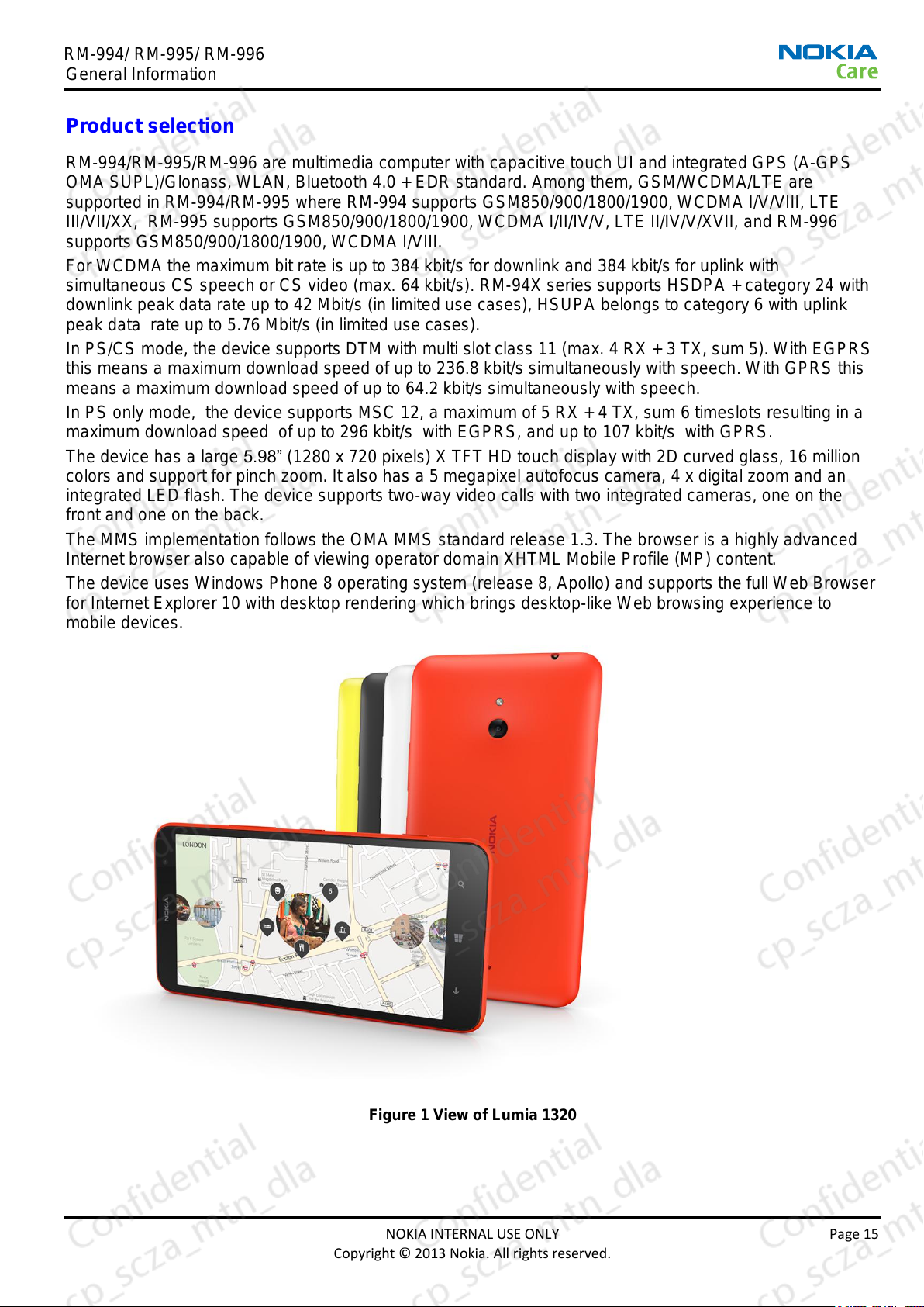
The device has a large 5.98” (1280 x 720 pixels) X TFT HD touch display with 2D curved glass, 16 million
colors and support for pinch zoom. It also has a 5 megapixel autofocus camera, 4 x digital zoom and an
integrated LED flash. The device supports two-way video calls with two integrated cameras, one on the
front and one on the back.
The MMS implementation follows the OMA MMS standard release 1.3. The browser is a highly advanced
Internet browser also capable of viewing operator domain XHTML Mobile Profile (MP) content.
The device uses Windows Phone 8 operating system (release 8, Apollo) and supports the full Web Browser
for Internet Explorer 10 with desktop rendering which brings desktop-like Web browsing experience to
mobile devices.
Figure 1 View of Lumia 1320
NOKIA INTERNAL USE ONLY Page 15
Copyright © 2013 Nokia. All rights reserved.
RM-994/ RM-995/ RM-996
General Information
Product features and sales package
Imaging
Main camera:
● Sensor: 5 megapixel
● F number/Aperture: F2.4
● Digital zoom: 4x
● Auto focus: Two-stage capture key
● Focus range: 10 cm ~ infinity
● Flash: Integrated LED flash
Front facing camera:
● Sensor: VGA (640 x 480 pixels)
● F number/Aperture: F2.8
● Fixed focus
Video:
● Video resolution: nHD 30 fps (1080p)
● Audio recording: High amplitude audio capture
● Video stabilization
● Video clip length: Max. 90 min
● Video file format: .mp4 H.264
● White balance: Automatic, sunny, cloudy, incandescent, fluorescent
● Zoom (digital): 4x
Continuous auto focus
● Touch focus
● Video recording indicator
Photo:
● Still image resolutions: 5M (4:3), 3.8M (16:9)
● Still image file format: JPEG/EXIF
● View finder: Full screen view finder
● Continuous autofocus
● Touch focus
● Auto exposure: Center weighted AE
● Image orientation: Automatic
● Exposure compensation: +2 ~ -2EV at 0.5 step
● White balance: Automatic, sunny, cloudy, incandescent, fluorescent
● Zoom (digital): Up to 4x
Edit
● On device Photo editor (manual & automatic)
Page 16 NOKIA INTERNAL USE ONLY
Copyright © 2013 Nokia. All rights reserved.
RM-994/ RM-995/ RM-996
General Information
View
● 5.98” TFT HD (1280 x 720 pixels) color display, up to 16M colors
● Capacitive touch
● Corning® Gorilla® Glass (7N)
● 2D curved glass
● Alphamon sensor - a combination of ALS and proximity, ALS to optimize display brightness and power
consumption, Proximity for turning off the display when in a call for power consumption.
● Slideshow from Pictures
Share
● Share effortlessly from Pictures or after capture
● Video sharing support (WCDMAD/LTE services)
● Online Album: Image/Video uploading from Pictures
Store
● 8 GB internal memory
● 1 GB RAM
● Micro SD support up to 64 GB
● Easy to transfer and organize photos and video between your device and a compatible PC
Music
● Digital music player: Supports MPEG-4 AAC/ AAC+/ eAAC+/ MPEG-1 audio Layer3 (MP3)/ WMA Pro
9 and 10
● Synchronies music with PC application
High Dynamic Range (HDR) microphones
● Bluetooth speakers
● Integrated hands free speaker
Media
● Full-screen video playback to view downloaded, streamed or recorded video clips
● Supported video formats: MPEG-4, H.264/AVC, H.263/3GPP, WMV, AVI, MOV.
Productivity
Context management:
● Internet Explorer 10 with desktop rendering
● OMA DRM version 2.0
● OTA provisioning
Messaging:
● E-mail (SMTP, IMAP4, POP3), MMS, SMS, unified editor
Office applications:
● Viewing of email attachments – doc, .xls, .ppt, .pdf, .zip
● Mail for Exchange
● Rich HTML
● Office 15, SharePoint 15, Office 365
NOKIA INTERNAL USE ONLY Page 17
Copyright © 2013 Nokia. All rights reserved.
RM-994/ RM-995/ RM-996
General Information
PIM:
● Contacts, calendar, calculator, clock, To-do, Notes
Synchronization:
● Local/Remote (using SkyDrive)
● Data: Calendar, Contacts, E-mail, To-do list.
● PC Applications: Microsoft Outlook (98, 2000, 2002, 2003), Outlook Express
Call management:
● Call logs, speed dial, voice dialing (with SIND) and voice commands
Connectivity
● Integrated GPS (A-GPS OMA SUPL) and Glonass
● WLAN - IEEE802.11 b/g/n with 2.4GHz
● Micro USB interface with USB 2.0 high speed
● Bluetooth wireless technology 4.0 + EDR
● Nokia 3.5 mm AV connector
Additional technical specifications
● Vibrating alert
● 3GPP Rel 8/6 compliant
● Speech codecs supported: FR, EFR, HR, AMR-NB, AMR-WB
● 1.7 GHz dual core processor
● WCDMA DL 384 kbit/s, UL 384 kbit/s
● GPRS/EGPRS Class B, multi slot class 12
● Dual Transfer Mode (DTM) class A, multi slot class 11
● HSDPA up to 21.1 Mbit/s, HSUPA 5.76 Mbit/s
● LTE support CAT3 DL 100 Mbit/s, UL 50 Mbit/s
Sales package
● Transceiver RM-994/ RM-995/ RM-996
● USB charger
RM-994 (AC-60 E/U/X/N/AR/K/A)
RM-995 (AC-60 uUSB black charger)
RM-996 (AC-50C for china)
● Music headset (WH-108)
● Connectivity cable (CA-189CD/ CA-190CD)
● Product information booklet
● Quick Start Guide
Page 18 NOKIA INTERNAL USE ONLY
Copyright © 2013 Nokia. All rights reserved.
RM-994/ RM-995/ RM-996
Module name
Type code
Notes
System/RF module PWB
Sub PWB module
Flash flex module
3VW
3VX
3VZ
Part of CWS carrier assembly
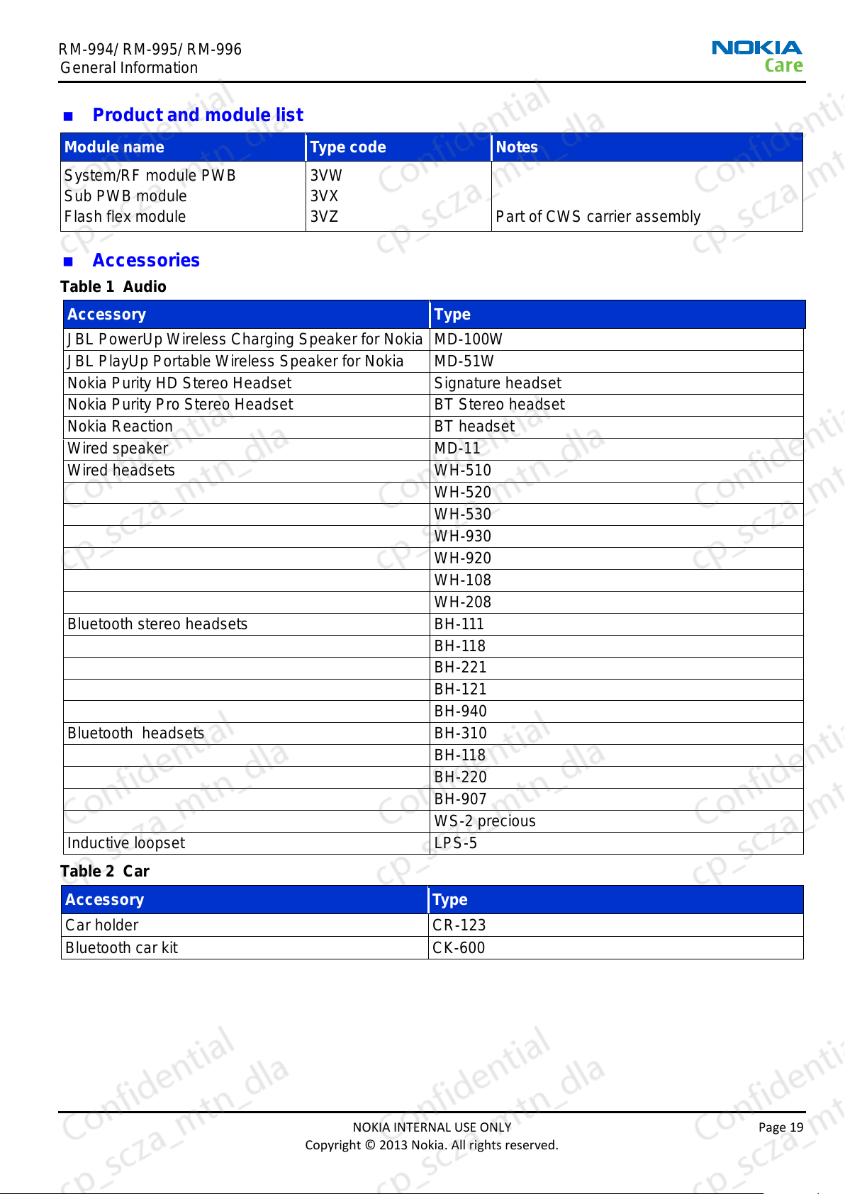
Accessory
Type
JBL PowerUp Wireless Charging Speaker for Nokia
MD-100W
JBL PlayUp Portable Wireless Speaker for Nokia
MD-51W
Nokia Purity HD Stereo Headset
Signature headset
Nokia Purity Pro Stereo Headset
BT Stereo headset
Nokia Reaction
BT headset
Wired speaker
MD-11
Wired headsets
WH-510
WH-520
WH-530
WH-930
WH-920
WH-108
WH-208
Bluetooth stereo headsets
BH-111
BH-118
BH-221
BH-121
BH-940
Bluetooth headsets
BH-310
BH-118
BH-220
BH-907
WS-2 precious
Inductive loopset
LPS-5
Accessory
Type
Car holder
CR-123
Bluetooth car kit
CK-600
General Information
Product and module list
Accessories
Table 1 Audio
Table 2 Car
NOKIA INTERNAL USE ONLY Page 19
Copyright © 2013 Nokia. All rights reserved.
RM-994/ RM-995/ RM-996
Accessory
Type
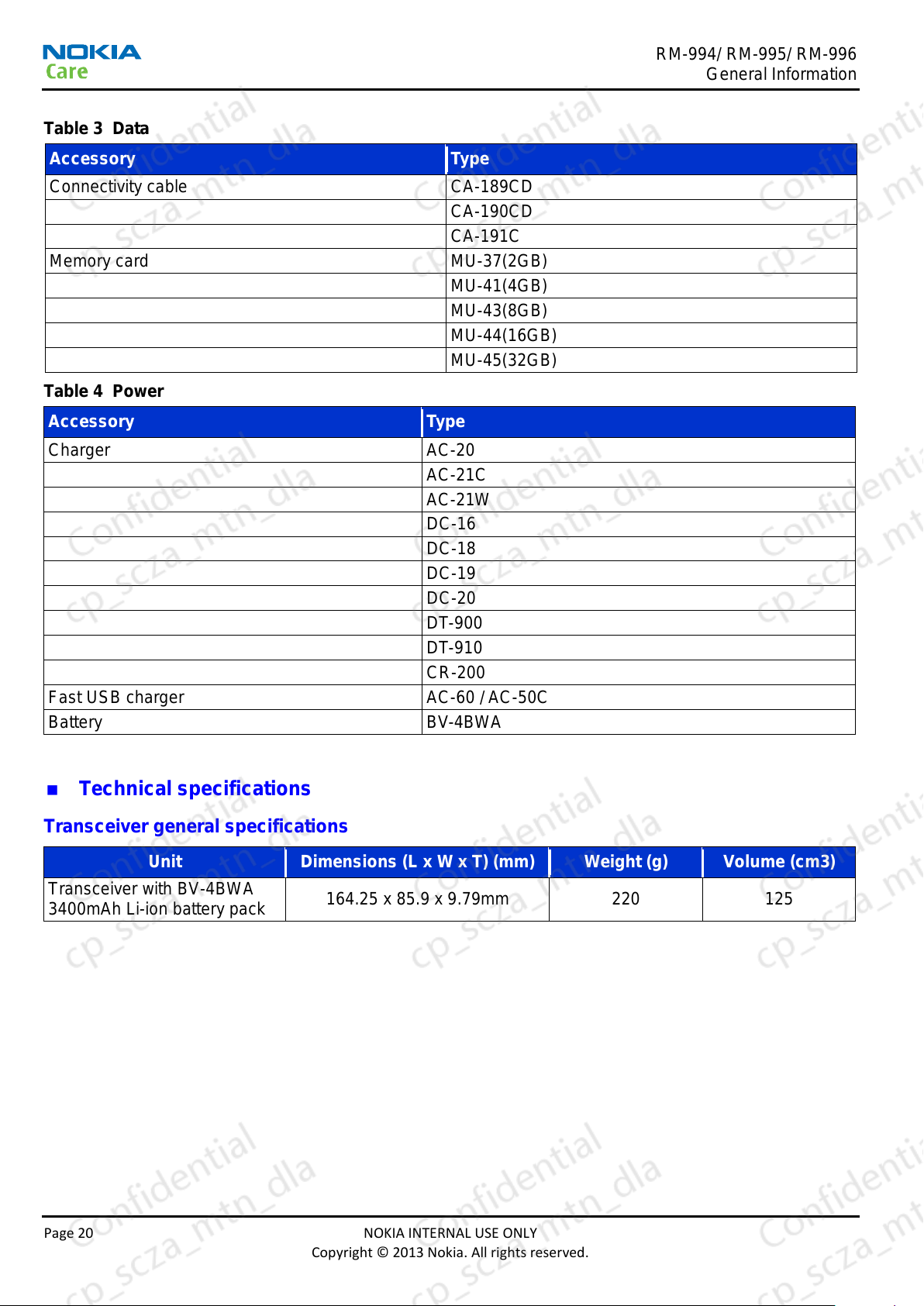
Connectivity cable
CA-189CD
CA-190CD
CA-191C
Memory card
MU-37(2GB)
MU-41(4GB)
MU-43(8GB)
MU-44(16GB)
MU-45(32GB)
Accessory
Type
Charger
AC-20
AC-21C
AC-21W
DC-16
DC-18
DC-19
DC-20
DT-900
DT-910
CR-200
Fast USB charger
AC-60 / AC-50C
Battery
BV-4BWA
Unit
Dimensions (L x W x T) (mm)
Weight (g)
Volume (cm3)
Transceiver with BV-4BWA
3400mAh Li-ion battery pack
164.25 x 85.9 x 9.79mm
220
125
General Information
Table 3 Data
Table 4 Power
Technical specifications
Transceiver general specifications
Page 20 NOKIA INTERNAL USE ONLY
Copyright © 2013 Nokia. All rights reserved.
RM-994/ RM-995/ RM-996
Parameter
Unit
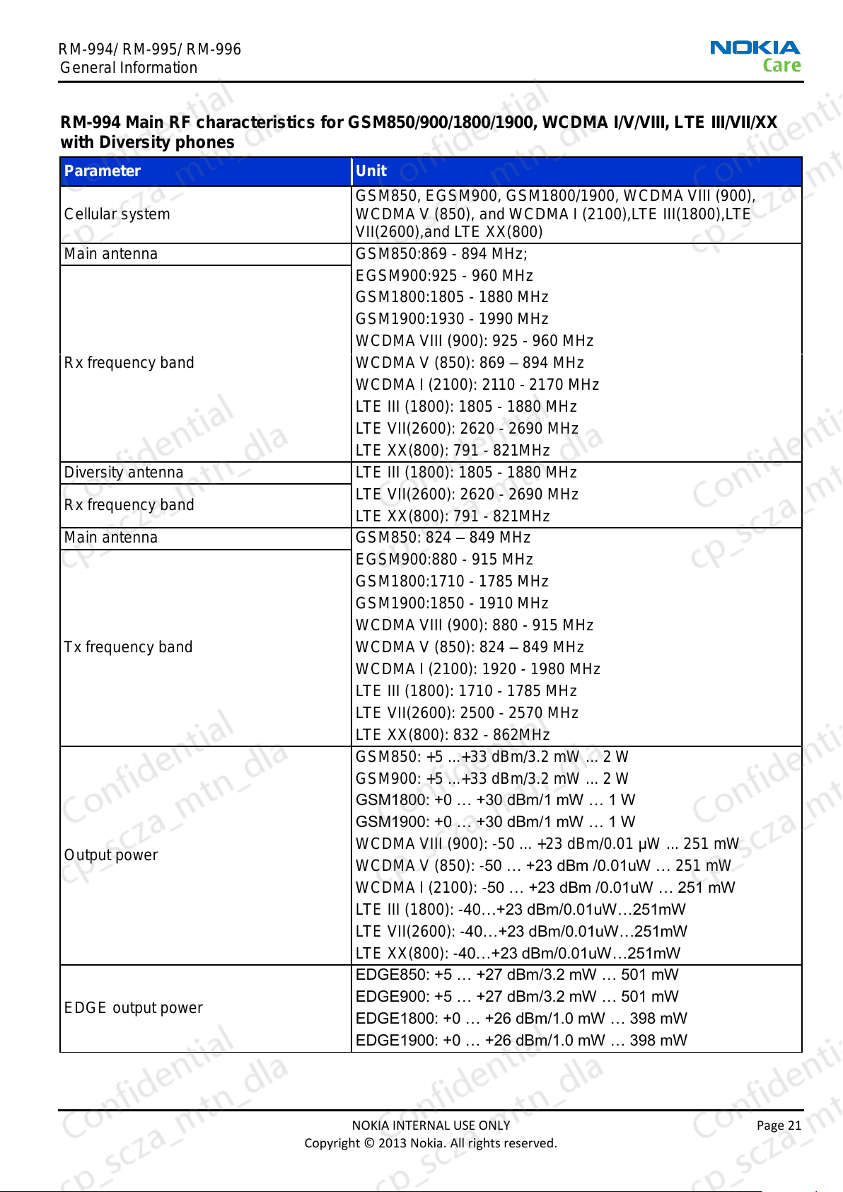
Cellular system
GSM850, EGSM900, GSM1800/1900, WCDMA VIII (900),
WCDMA V (850), and WCDMA I (2100),LTE III(1800),LTE
VII(2600),and LTE XX(800)
Main antenna
GSM850:869 - 894 MHz;
Rx frequency band
EGSM900:925 - 960 MHz
GSM1800:1805 - 1880 MHz
GSM1900:1930 - 1990 MHz
WCDMA VIII (900): 925 - 960 MHz
WCDMA V (850): 869 – 894 MHz
WCDMA I (2100): 2110 - 2170 MHz
LTE III (1800): 1805 - 1880 MHz
LTE VII(2600): 2620 - 2690 MHz
LTE XX(800): 791 - 821MHz
Diversity antenna
LTE III (1800): 1805 - 1880 MHz
Rx frequency band
LTE VII(2600): 2620 - 2690 MHz
LTE XX(800): 791 - 821MHz
Main antenna
GSM850: 824 – 849 MHz
Tx frequency band
EGSM900:880 - 915 MHz
GSM1800:1710 - 1785 MHz
GSM1900:1850 - 1910 MHz
WCDMA VIII (900): 880 - 915 MHz
WCDMA V (850): 824 – 849 MHz
WCDMA I (2100): 1920 - 1980 MHz
LTE III (1800): 1710 - 1785 MHz
LTE VII(2600): 2500 - 2570 MHz
LTE XX(800): 832 - 862MHz
Output power
GSM850: +5 ...+33 dBm/3.2 mW ... 2 W
GSM900: +5 ...+33 dBm/3.2 mW ... 2 W
GSM1800: +0 … +30 dBm/1 mW … 1 W
GSM1900: +0 … +30 dBm/1 mW … 1 W
WCDMA VIII (900): -50 ... +23 dBm/0.01 μW ... 251 mW
WCDMA V (850): -50 … +23 dBm /0.01uW … 251 mW
WCDMA I (2100): -50 … +23 dBm /0.01uW … 251 mW
LTE III (1800): -40…+23 dBm/0.01uW…251mW
LTE VII(2600): -40…+23 dBm/0.01uW…251mW
LTE XX(800): -40…+23 dBm/0.01uW…251mW
EDGE output power
EDGE850: +5 … +27 dBm/3.2 mW … 501 mW
EDGE900: +5 … +27 dBm/3.2 mW … 501 mW
EDGE1800: +0 … +26 dBm/1.0 mW … 398 mW
EDGE1900: +0 … +26 dBm/1.0 mW … 398 mW
General Information
RM-994 Main RF characteristics for GSM850/900/1800/1900, WCDMA I/V/VIII, LTE III/VII/XX
with Diversity phones
NOKIA INTERNAL USE ONLY Page 21
Copyright © 2013 Nokia. All rights reserved.
RM-994/ RM-995/ RM-996
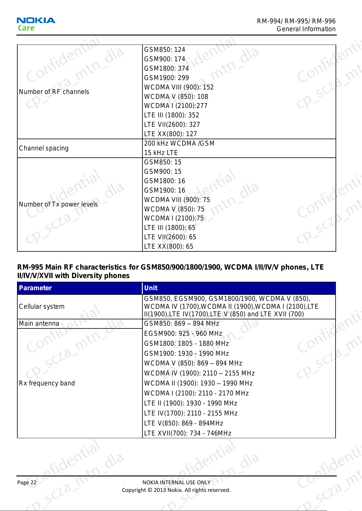
Number of RF channels
GSM850: 124
GSM900: 174
GSM1800: 374
GSM1900: 299
WCDMA VIII (900): 152
WCDMA V (850): 108
WCDMA I (2100):277
LTE III (1800): 352
LTE VII(2600): 327
LTE XX(800): 127
Channel spacing
200 kHz WCDMA /GSM
15 kHz LTE
Number of Tx power levels
GSM850: 15
GSM900: 15
GSM1800: 16
GSM1900: 16
WCDMA VIII (900): 75
WCDMA V (850): 75
WCDMA I (2100):75
LTE III (1800): 65
LTE VII(2600): 65
LTE XX(800): 65
Parameter
Unit
Cellular system
GSM850, EGSM900, GSM1800/1900, WCDMA V (850),
WCDMA IV (1700),WCDMA II (1900),WCDMA I (2100),LTE
II(1900),LTE IV(1700),LTE V (850) and LTE XVII (700)
Main antenna
GSM850: 869 – 894 MHz
Rx frequency band
EGSM900: 925 - 960 MHz
GSM1800: 1805 - 1880 MHz
GSM1900: 1930 - 1990 MHz
WCDMA V (850): 869 – 894 MHz
WCDMA IV (1900): 2110 – 2155 MHz
WCDMA II (1900): 1930 – 1990 MHz
WCDMA I (2100): 2110 - 2170 MHz
LTE II (1900): 1930 - 1990 MHz
LTE IV(1700): 2110 - 2155 MHz
LTE V(850): 869 - 894MHz
LTE XVII(700): 734 - 746MHz
General Information
RM-995 Main RF characteristics for GSM850/900/1800/1900, WCDMA I/II/IV/V phones, LTE
II/IV/V/XVII with Diversity phones
Page 22 NOKIA INTERNAL USE ONLY
Copyright © 2013 Nokia. All rights reserved.
RM-994/ RM-995/ RM-996
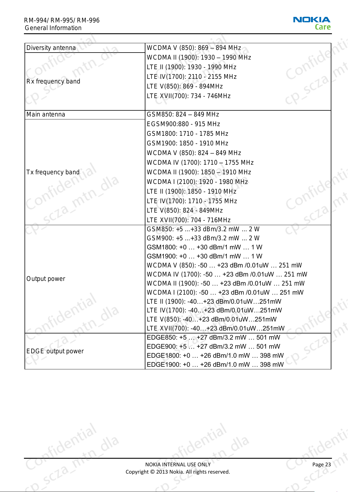
Diversity antenna
WCDMA V (850): 869 – 894 MHz
Rx frequency band
WCDMA II (1900): 1930 – 1990 MHz
LTE II (1900): 1930 - 1990 MHz
LTE IV(1700): 2110 - 2155 MHz
LTE V(850): 869 - 894MHz
LTE XVII(700): 734 - 746MHz
Main antenna
GSM850: 824 – 849 MHz
Tx frequency band
EGSM900:880 - 915 MHz
GSM1800: 1710 - 1785 MHz
GSM1900: 1850 - 1910 MHz
WCDMA V (850): 824 – 849 MHz
WCDMA IV (1700): 1710 – 1755 MHz
WCDMA II (1900): 1850 – 1910 MHz
WCDMA I (2100): 1920 - 1980 MHz
LTE II (1900): 1850 - 1910 MHz
LTE IV(1700): 1710 - 1755 MHz
LTE V(850): 824 - 849MHz
LTE XVII(700): 704 - 716MHz
Output power
GSM850: +5 ...+33 dBm/3.2 mW ... 2 W
GSM900: +5 ...+33 dBm/3.2 mW ... 2 W
GSM1800: +0 … +30 dBm/1 mW … 1 W
GSM1900: +0 … +30 dBm/1 mW … 1 W
WCDMA V (850): -50 … +23 dBm /0.01uW … 251 mW
WCDMA IV (1700): -50 … +23 dBm /0.01uW … 251 mW
WCDMA II (1900): -50 … +23 dBm /0.01uW … 251 mW
WCDMA I (2100): -50 … +23 dBm /0.01uW … 251 mW
LTE II (1900): -40…+23 dBm/0.01uW…251mW
LTE IV(1700): -40…+23 dBm/0.01uW…251mW
LTE V(850): -40…+23 dBm/0.01uW…251mW
LTE XVII(700): -40…+23 dBm/0.01uW…251mW
EDGE output power
EDGE850: +5 … +27 dBm/3.2 mW … 501 mW
EDGE900: +5 … +27 dBm/3.2 mW … 501 mW
EDGE1800: +0 … +26 dBm/1.0 mW … 398 mW
EDGE1900: +0 … +26 dBm/1.0 mW … 398 mW
General Information
NOKIA INTERNAL USE ONLY Page 23
Copyright © 2013 Nokia. All rights reserved.
RM-994/ RM-995/ RM-996
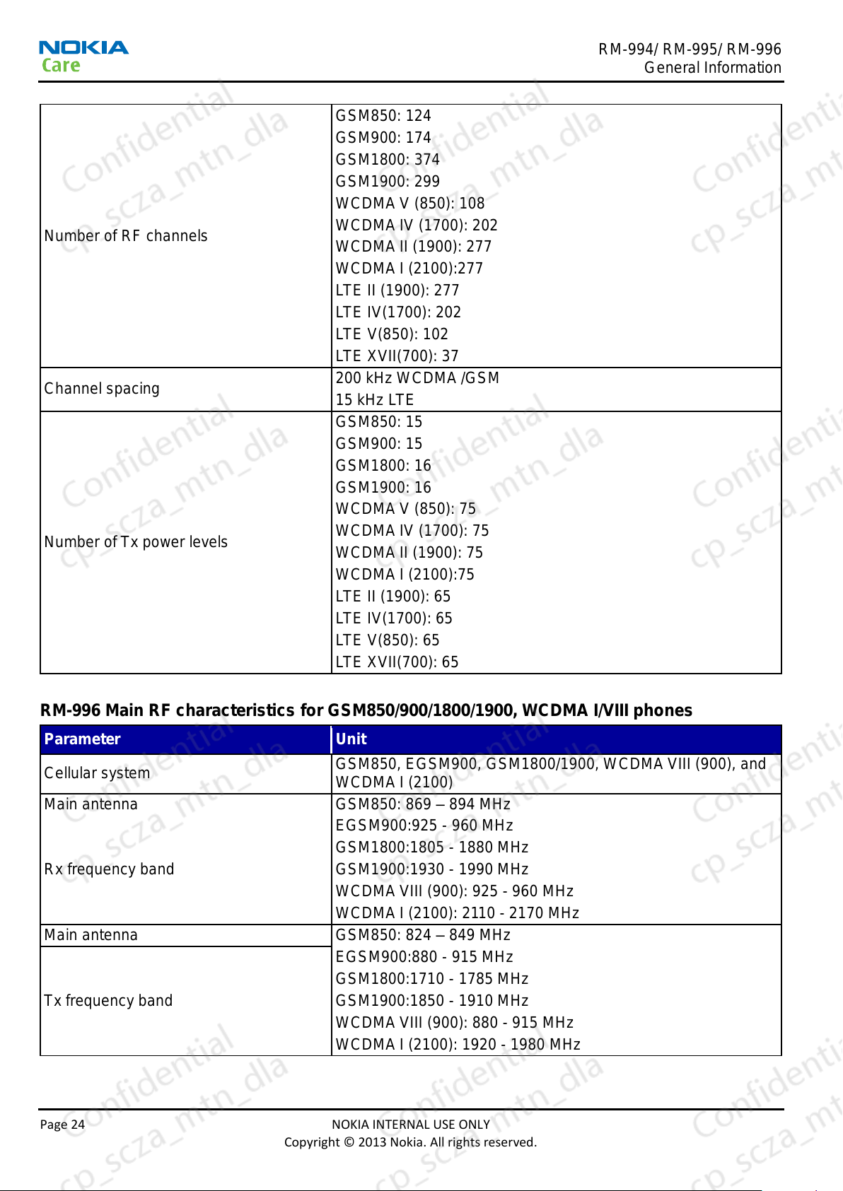
Number of RF channels
GSM850: 124
GSM900: 174
GSM1800: 374
GSM1900: 299
WCDMA V (850): 108
WCDMA IV (1700): 202
WCDMA II (1900): 277
WCDMA I (2100):277
LTE II (1900): 277
LTE IV(1700): 202
LTE V(850): 102
LTE XVII(700): 37
Channel spacing
200 kHz WCDMA /GSM
15 kHz LTE
Number of Tx power levels
GSM850: 15
GSM900: 15
GSM1800: 16
GSM1900: 16
WCDMA V (850): 75
WCDMA IV (1700): 75
WCDMA II (1900): 75
WCDMA I (2100):75
LTE II (1900): 65
LTE IV(1700): 65
LTE V(850): 65
LTE XVII(700): 65
Parameter
Unit
Cellular system
GSM850, EGSM900, GSM1800/1900, WCDMA VIII (900), and
WCDMA I (2100)
Main antenna
GSM850: 869 – 894 MHz
Rx frequency band
EGSM900:925 - 960 MHz
GSM1800:1805 - 1880 MHz
GSM1900:1930 - 1990 MHz
WCDMA VIII (900): 925 - 960 MHz
WCDMA I (2100): 2110 - 2170 MHz
Main antenna
GSM850: 824 – 849 MHz
Tx frequency band
EGSM900:880 - 915 MHz
GSM1800:1710 - 1785 MHz
GSM1900:1850 - 1910 MHz
WCDMA VIII (900): 880 - 915 MHz
WCDMA I (2100): 1920 - 1980 MHz
General Information
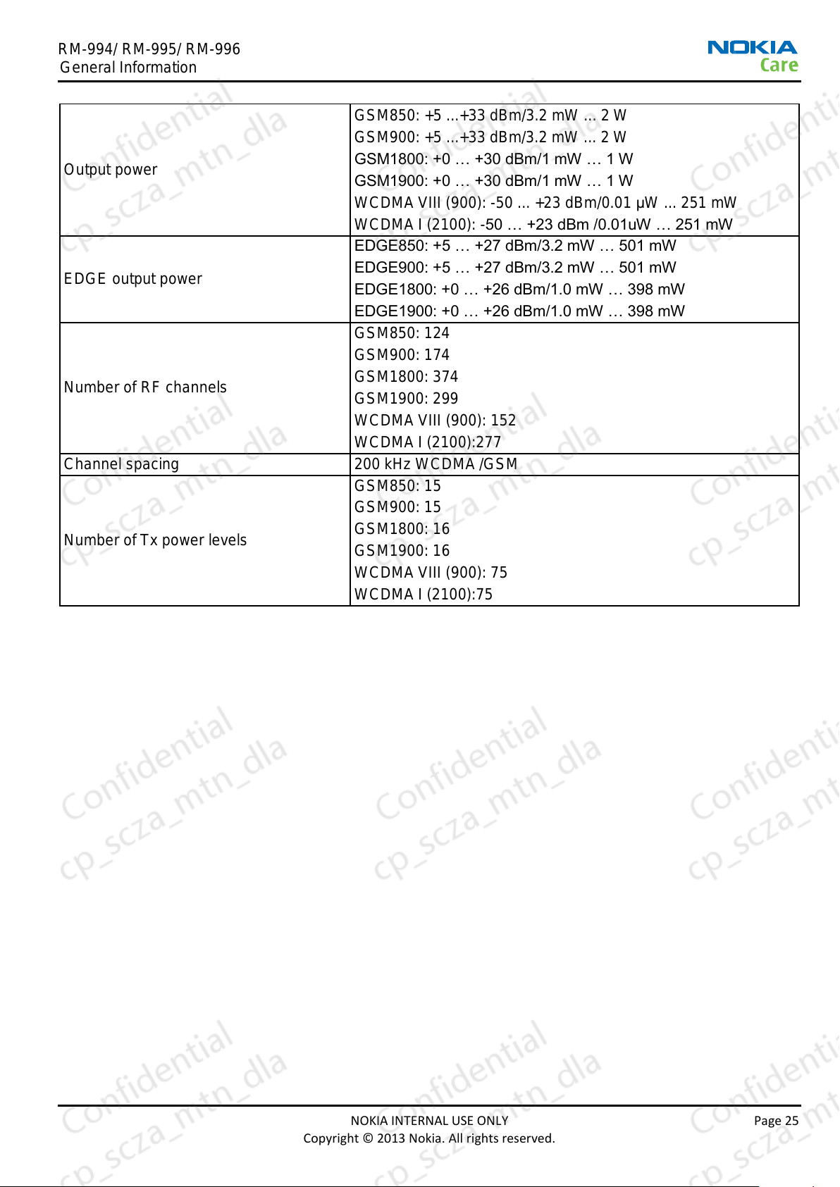
RM-996 Main RF characteristics for GSM850/900/1800/1900, WCDMA I/VIII phones
Page 24 NOKIA INTERNAL USE ONLY
Copyright © 2013 Nokia. All rights reserved.
RM-994/ RM-995/ RM-996
Output power
GSM850: +5 ...+33 dBm/3.2 mW ... 2 W
GSM900: +5 ...+33 dBm/3.2 mW ... 2 W
GSM1800: +0 … +30 dBm/1 mW … 1 W
GSM1900: +0 … +30 dBm/1 mW … 1 W
WCDMA VIII (900): -50 ... +23 dBm/0.01 μW ... 251 mW
WCDMA I (2100): -50 … +23 dBm /0.01uW … 251 mW
EDGE output power
EDGE850: +5 … +27 dBm/3.2 mW … 501 mW
EDGE900: +5 … +27 dBm/3.2 mW … 501 mW
EDGE1800: +0 … +26 dBm/1.0 mW … 398 mW
EDGE1900: +0 … +26 dBm/1.0 mW … 398 mW
Number of RF channels
GSM850: 124
GSM900: 174
GSM1800: 374
GSM1900: 299
WCDMA VIII (900): 152
WCDMA I (2100):277
Channel spacing
200 kHz WCDMA /GSM
Number of Tx power levels
GSM850: 15
GSM900: 15
GSM1800: 16
GSM1900: 16
WCDMA VIII (900): 75
WCDMA I (2100):75
General Information
NOKIA INTERNAL USE ONLY Page 25
Copyright © 2013 Nokia. All rights reserved.
RM-994/ RM-995/ RM-996
Battery
Capacity(mAh)
Talk time
Stand-by
Music playback
HD video playback
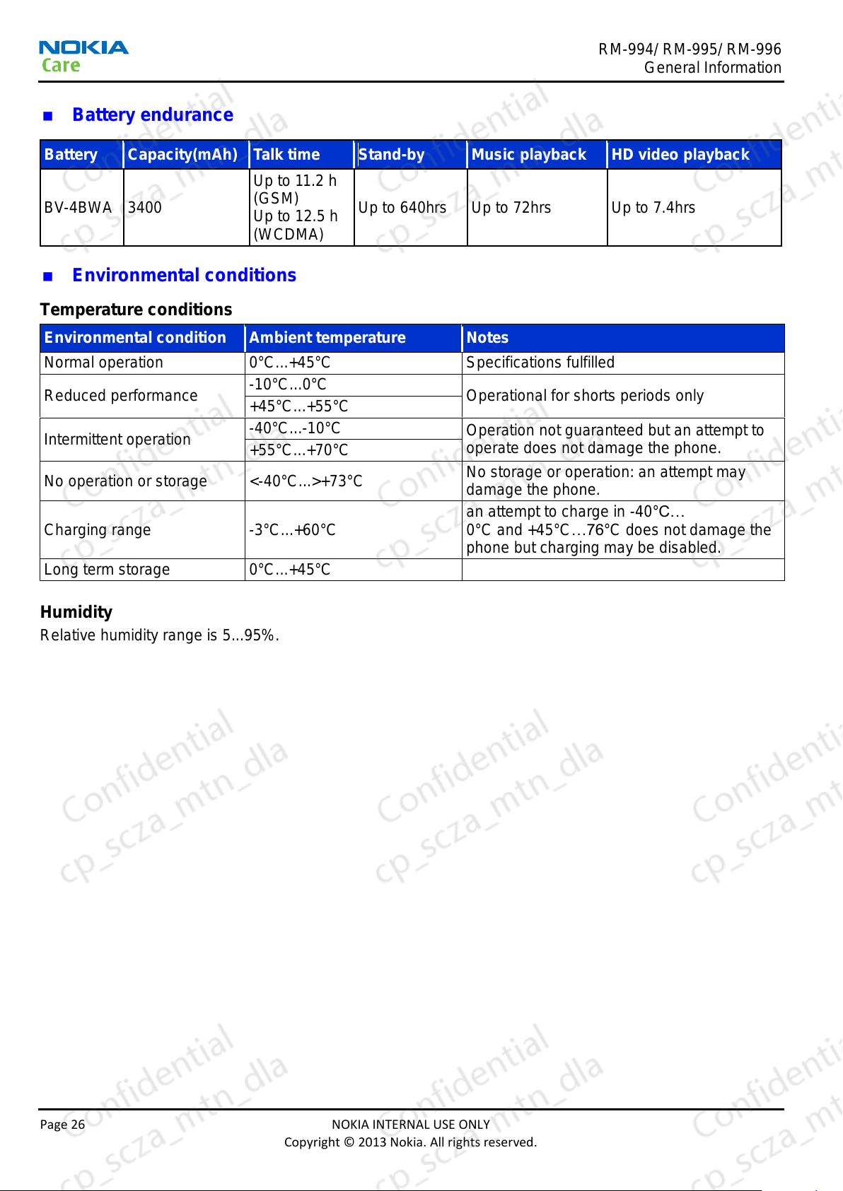
BV-4BWA
3400
Up to 11.2 h
(GSM)
Up to 12.5 h
(WCDMA)
Up to 640hrs
Up to 72hrs
Up to 7.4hrs
Environmental condition
Ambient temperature
Notes
Normal operation
0°C...+45°C
Specifications fulfilled
Reduced performance
-10°C...0°C
Operational for shorts periods only
+45°C...+55°C
Intermittent operation
-40°C...-10°C
Operation not guaranteed but an attempt to
operate does not damage the phone.
+55°C...+70°C
No operation or storage
<-40°C...>+73°C
No storage or operation: an attempt may
damage the phone.
Charging range
-3°C...+60°C
an attempt to charge in -40°C…
0°C and +45°C…76°C does not damage the
phone but charging may be disabled.
Long term storage
0°C...+45°C
General Information
Battery endurance
Environmental conditions
Temperature conditions
Humidity
Relative humidity range is 5...95%.
Page 26 NOKIA INTERNAL USE ONLY
Copyright © 2013 Nokia. All rights reserved.
RM-994/ RM-995/ RM-996
General Information
The HW module is not protected against water. Condensed or splashed water might cause malfunction.
Any submersion of the phone will cause permanent damage. Long-term high humidity, with condensation,
will cause permanent damage because of corrosion.
Vibration
The module should withstand the following vibrations:
• 1200rpm
• 50dB(A)max
ESD strength
Conducted discharge is 4 kV (>10 discharges) and air contact 8 kV (>10 discharges).
The standard for electrostatic discharge is IEC 61000-4-2, and this device fulfills level 4 requirements.
RoHS
This device uses RoHS compliant components and lead-free soldering process.
NOKIA INTERNAL USE ONLY Page 27
Copyright © 2013 Nokia. All rights reserved.

RM-994/ RM-995/ RM-996
General Information
(This page left intentionally blank.)
Page 28 NOKIA INTERNAL USE ONLY
Copyright © 2013 Nokia. All rights reserved.
Nokia Customer Care
2 Service Tools and Service
Concepts
NOKIA INTERNAL USE ONLY Page 29
Copyright © 2013 Nokia. All rights reserved.

RM-994/ RM-995/ RM-996
Service Tools and Service Concepts
(This page left intentionally blank.)
Page 30 NOKIA INTERNAL USE ONLY
Copyright © 2013 Nokia. All rights reserved.

RM-994/ RM-995/ RM-996
Service Tools and Service Concepts
Table of Contents
Service tools ............................................................................................................................................. 33
Nokia Product Specific Tools ................................................................................................................33
SS-305 ........................................................................................................................................ 33
SS-298 ........................................................................................................................................ 33
General tools ........................................................................................................................................33
CA-101 ........................................................................................................................................ 33
RJ-245 ........................................................................................................................................ 33
SRT-6 ......................................................................................................................................... 34
SS-93 .......................................................................................................................................... 34
SX-4T.......................................................................................................................................... 34
Option Tools .........................................................................................................................................34
XRS-6 ......................................................................................................................................... 34
MJ-300 ................................................................................................................................ ........ 35
SS-334 ........................................................................................................................................ 35
PCS-1 ......................................................................................................................................... 35
Service concepts (Nokia) ......................................................................................................................... 36
POS (Point of Sale) flash concept ........................................................................................................36
Concept for flashing and product code change .....................................................................................37
Optional Module jig service concept 1 (Troubleshooting) ......................................................................38
Optional Module jig service concept 2 (Troubleshooting + RF Measurement) ......................................39
List of Figures
Figure 2 POS flash concept ....................................................................................................................... 36
Figure 3 BE concept for flashing and product code change ....................................................................... 37
Figure 4 BE Module jig service concept 1 .................................................................................................. 38
Figure 5 BE Module jig service concept 2 .................................................................................................. 39
NOKIA INTERNAL USE ONLY Page 31
Copyright © 2013 Nokia. All rights reserved.

RM-994/ RM-995/ RM-996
Service Tools and Service Concepts
(This page left intentionally blank.)
Page 32 NOKIA INTERNAL USE ONLY
Copyright © 2013 Nokia. All rights reserved.

RM-994/ RM-995/ RM-996
SS-305
Camera removal tool
0781564
The camera removal tool SS-210 is used to remove/attach the
camera module from/to the socket.
SS-298
RF Coaxial Cable Tool
0781548
The RF Coaxial Cable tool is used to disconnect the coaxial cable in
the device.
CA-101
Micro USB cable
0730634
The CA-101 is a USB-to-micro USB data cable that allows
connections between the PC and the phone.
RJ-245
Soldering jig
0781484
RJ-245 is a soldering jig used for soldering and as a rework jig for the
engine module.
Service Tools and Service Concepts
Service tools
Nokia product specific tools
The table below gives a short overview of service devices that can be used for testing error analysis, and
repair of product RM-994/RM-995/RM-996. For the correct use of the service devices and the best effort of
workbench setup please refer to various concepts.
General tools
The table below gives a short overview of service devices that can be used for testing, error analysis, and
repair of product. For the correct use of the service devices, and the best effort of workbench setup, please
refer to various concepts.
NOKIA INTERNAL USE ONLY Page 33
Copyright © 2013 Nokia. All rights reserved.

RM-994/ RM-995/ RM-996
SRT-6
Opening tool
0770431
SRT-6 is used to open phone covers.
Note: The SRT-6 is included in the Nokia Standard Toolkit.
SS-93
Opening tool
0780727
SS-93 is used for opening JAE connectors.
Note: The SS-93 is included in Nokia Standard Toolkit.
SX-4T
Smart card
0780392
SX-4T is a BB5 security device used to protect critical features in
tuning and testing.
XRS-6
RF cable
0730231
The RF cable is used to connect, for example, a module repair jig to
the RF measurement equipment.
Service Tools and Service Concepts
Optional tools
The table below gives a short overview of service devices that can be used for testing, error analysis and
repair of product. For the correct use of the service devices, and the best effort of workbench setup, please
refer to various concepts.
Page 34 NOKIA INTERNAL USE ONLY
Copyright © 2013 Nokia. All rights reserved.

RM-994/ RM-995/ RM-996
MJ-300
Module Jig
0781441
Module jig MJ-300 can be used for flashing via USB and RF, battery
and system testing.
The main functions are:
Powering with external power
WLAN/BT/GPS RF-interface with probes
GSM/WCDMA RF-interfaces with probes
BSI mode selector(Tabby and Lynx interface, selected with battery
cable)
VBATT interface (Tabby and Lynx interface, selected with battery
cable)
SS-314 RF guide plate is required with this jig
CA-158RS cable is used together with this jig for RF testing
SS-334
RF guide plate
0781609
SS-334 is an RF guide plate used with MJ-300 module jig
PCS-1
Power cable
0730012
The PCS-1 power cable (DC) is used with a docking station, a module
jig or a control unit to supply a controlled voltage
Service Tools and Service Concepts
NOKIA INTERNAL USE ONLY Page 35
Copyright © 2013 Nokia. All rights reserved.

RM-994/ RM-995/ RM-996
Type
Description
Product Specific Devices
BV-4BWA
Battery
Cables
CA-101
Micro USB cable
Service Tools and Service Concepts
Service concepts (Nokia)
POS (Point of Sale) flash concept
Figure 2 POS flash concept
Page 36 NOKIA INTERNAL USE ONLY
Copyright © 2013 Nokia. All rights reserved.

RM-994/ RM-995/ RM-996
Type
Description
Product Specific Devices
BV-4BWA
Battery
Other Devices
SX-4
Smart Card
Cables
CA-101
Micro USB cable
Service Tools and Service Concepts
Concept for flashing and product code change
Figure 3 BE concept for flashing and product code change
NOKIA INTERNAL USE ONLY Page 37
Copyright © 2013 Nokia. All rights reserved.

RM-994/ RM-995/ RM-996
Type
Description
Product Specific Devices
MJ-300
Module Jig
SS-334
RF guide plate
Cables
CA-101
Micro USB cable
PCS-1
DC Power cable
Service Tools and Service Concepts
Optional Module jig service concept 1 (Troubleshooting)
Figure 4 BE Module jig service concept 1
Page 38 NOKIA INTERNAL USE ONLY
Copyright © 2013 Nokia. All rights reserved.

RM-994/ RM-995/ RM-996
Type
Description
Product Specific Devices
MJ-305
Module Jig
SS-334
RF guide plate
Cables
CA-101
Micro USB cable
PCS-1
DC Power cable
XRS-6
RF cable
Service Tools and Service Concepts
Optional Module jig service concept 2 (Troubleshooting + RF Measurement)
Figure 5 BE Module jig service concept 2
NOKIA INTERNAL USE ONLY Page 39
Copyright © 2013 Nokia. All rights reserved.

RM-994/ RM-995/ RM-996
Service Tools and Service Concepts
(This page left intentionally blank.)
Page 40 NOKIA INTERNAL USE ONLY
Copyright © 2013 Nokia. All rights reserved.

Nokia Customer Care
3 BB Troubleshooting Guide
NOKIA INTERNAL USE ONLY Page 41
Copyright © 2013 Nokia. All rights reserved.

RM-994/ RM-995/ RM-996
BB Troubleshooting Guide
(This page left intentionally blank.)
Page 42 NOKIA INTERNAL USE ONLY
Copyright © 2013 Nokia. All rights reserved.

RM-994/ RM-995/ RM-996
BB Troubleshooting Guide
Table of Contents
Placement ................................................................................................................................................. 45
Placement – Main Board (Top side) ......................................................................................................45
Placement - Main Board (Bottom side) .................................................................................................46
Placement - D-Cover ............................................................................................................................47
Placement - A_Cover( Include TP ,LCM) ..............................................................................................48
How to power on Handset ........................................................................................................................ 49
Push Power Key ...................................................................................................................................49
Short TP11 and GND ............................................................................................................................49
Overall Troubleshooting flow .................................................................................................................. 50
General power checking troubleshooting ..............................................................................................53
Dead or jammed device troubleshooting...............................................................................................55
Clocking troubleshooting ......................................................................................................................56
USB Charging troubleshooting .............................................................................................................57
Interface Troubleshooting ........................................................................................................................ 58
USB data interface troubleshooting ......................................................................................................58
SIM card troubleshooting ......................................................................................................................59
Micro SD interface troubleshooting .......................................................................................................60
DRAM troubleshooting .........................................................................................................................61
eMMC troubleshooting .........................................................................................................................62
Display Module Troubleshooting ............................................................................................................ 63
Display Fault troubleshooting ...............................................................................................................65
Touch Panel troubleshooting ................................................................................................................66
Keyboard troubleshooting .....................................................................................................................67
Sensor Troubleshooting .......................................................................................................................... 68
Accelerometer troubleshooting .............................................................................................................68
Accelerometer troubleshooting .............................................................................................................69
Proximity sensor and ambient light sensor (ALS) .................................................................................70
ALS troubleshooting .............................................................................................................................71
Proximity troubleshooting .....................................................................................................................72
Audio Troubleshooting ................................................................ ............................................................ 73
Audio troubleshooting test instructions .................................................................................................73
External earpiece troubleshooting ........................................................................................................74
Internal Earpiece troubleshooting .........................................................................................................75
Internal Handsfree Speaker troubleshooting .........................................................................................76
Vibra Troubleshooting ...........................................................................................................................77
Connectivity Module Troubleshooting .................................................................................................... 78
Introduction to connectivity module troubleshooting .............................................................................78
BT Antenna troubleshooting .................................................................................................................80
WLAN Antenna troubleshooting ............................................................................................................81
NOKIA INTERNAL USE ONLY Page 43
Copyright © 2013 Nokia. All rights reserved.

RM-994/ RM-995/ RM-996
BB Troubleshooting Guide
GPS Antenna troubleshooting .............................................................................................................. 82
Introduction to GPS troubleshooting ..................................................................................................... 82
List of Tables
Table 5 Display module troubleshooting cases ........................................................................................... 63
Table 6 Pixel defects .................................................................................................................................. 63
Table 7 Defects table.................................................................................................................................. 64
List of Figures
Figure 6 CWR block diagram ..................................................................................................................... 78
Figure 7 LDS antenna positions ................................................................................................................. 79
Figure 8 WLAN/BT component layout ........................................................................................................ 79
Figure 9 Phone Menus->HERE Maps ........................................................................................................ 82
Figure 10 GPS Maps .................................................................................................................................. 82
Page 44 NOKIA INTERNAL USE ONLY
Copyright © 2013 Nokia. All rights reserved.

RM-994/ RM-995/ RM-996
uSD Socket
G-Sensor
2G/3G PA
WLNSP
WCN3660
MSM89x0 & DDR
8Gbit
P/L Sensor
CONN
REC Contact
PM8038
19.2MHz Crystal
Thermal Resistor
48MHz Crystal
MIC
LTE PA
Front Camera
LTE PA
27MHz Crystal
BB Troubleshooting Guide
Placement
Placement – Main Board (Top side)
NOKIA INTERNAL USE ONLY Page 45
Copyright © 2013 Nokia. All rights reserved.

RM-994/ RM-995/ RM-996
Diversity CONN
Diversity SPR
CONN
Volume Up
Volume Down
Power Key
Camera Key
Main Antenna
SPR CONN
Speaker
Contact
Vibrator
Contact
USB Connector
Display
Connector
Battery
Connector
SIM
Socket
BT/Wi-Fi/GPS
SPR CONN
BT/Wi-Fi/GPS
CONN
Audio Jack
Touch
CONN
8G eMMC
2G/3G CONN
Flash LED
contact
5MP Camera
BB Troubleshooting Guide
Placement - Main Board (Bottom side)
Page 46 NOKIA INTERNAL USE ONLY
Copyright © 2013 Nokia. All rights reserved.

RM-994/ RM-995/ RM-996
BT/Wi-Fi/GPS
Antenna
Vibrator
Speaker
Main Antenna
Flash LED
Diversity
Antenna
BB Troubleshooting Guide
D-Cover
NOKIA INTERNAL USE ONLY Page 47
Copyright © 2013 Nokia. All rights reserved.

RM-994/ RM-995/ RM-996
Touch Panel
FPC
Receiver
Volume Up
Power Key
Camera Key
Volume Down
Coaxial Cable
Coaxial Cable
Side Key FPC
LCM FPC
P-Sensor
BB Troubleshooting Guide
A_COVER (Include Touch Panel, LCM)
Page 48 NOKIA INTERNAL USE ONLY
Copyright © 2013 Nokia. All rights reserved.

RM-994/ RM-995/ RM-996
Press power
key for 5 sec
Short TP11 and GND together
at least 5sec
BB Troubleshooting Guide
How to power on Handset
1. Push power key
2. Short TP11 and GND.
NOKIA INTERNAL USE ONLY Page 49
Copyright © 2013 Nokia. All rights reserved.

RM-994/ RM-995/ RM-996
BB Troubleshooting Guide
Overall Troubleshooting flow
Page 50 NOKIA INTERNAL USE ONLY
Copyright © 2013 Nokia. All rights reserved.

RM-994/ RM-995/ RM-996
BB Troubleshooting Guide
NOKIA INTERNAL USE ONLY Page 51
Copyright © 2013 Nokia. All rights reserved.

RM-994/ RM-995/ RM-996
BB Troubleshooting Guide
Page 52 NOKIA INTERNAL USE ONLY
Copyright © 2013 Nokia. All rights reserved.

RM-994/ RM-995/ RM-996
BB Troubleshooting Guide
General power checking troubleshooting
NOKIA INTERNAL USE ONLY Page 53
Copyright © 2013 Nokia. All rights reserved.

RM-994/ RM-995/ RM-996
BB Troubleshooting Guide
Page 54 NOKIA INTERNAL USE ONLY
Copyright © 2013 Nokia. All rights reserved.

RM-994/ RM-995/ RM-996
BB Troubleshooting Guide
Dead or jammed device troubleshooting
NOKIA INTERNAL USE ONLY Page 55
Copyright © 2013 Nokia. All rights reserved.

RM-994/ RM-995/ RM-996
BB Troubleshooting Guide
Clocking troubleshooting
Page 56 NOKIA INTERNAL USE ONLY
Copyright © 2013 Nokia. All rights reserved.

RM-994/ RM-995/ RM-996
BB Troubleshooting Guide
USB charging troubleshooting
NOKIA INTERNAL USE ONLY Page 57
Copyright © 2013 Nokia. All rights reserved.

RM-994/ RM-995/ RM-996
BB Troubleshooting Guide
Interface troubleshooting
USB data interface troubleshooting
Page 58 NOKIA INTERNAL USE ONLY
Copyright © 2013 Nokia. All rights reserved.

RM-994/ RM-995/ RM-996
BB Troubleshooting Guide
SIM card troubleshooting
NOKIA INTERNAL USE ONLY Page 59
Copyright © 2013 Nokia. All rights reserved.

RM-994/ RM-995/ RM-996
BB Troubleshooting Guide
MicroSD interface troubleshooting
Page 60 NOKIA INTERNAL USE ONLY
Copyright © 2013 Nokia. All rights reserved.

RM-994/ RM-995/ RM-996
BB Troubleshooting Guide
DRAM troubleshooting
NOKIA INTERNAL USE ONLY Page 61
Copyright © 2013 Nokia. All rights reserved.

RM-994/ RM-995/ RM-996
BB Troubleshooting Guide
eMMC troubleshooting
Page 62 NOKIA INTERNAL USE ONLY
Copyright © 2013 Nokia. All rights reserved.

RM-994/ RM-995/ RM-996
Display blank
there is no image on the display. The display looks the same
when the phone is on as it does when the phone is off.
Image on the display not correct
Image on the display can be corrupted or a part of the image
can be missing. If a part of the image is missing, change the
display module. If the image is otherwise corrupted, follow the
appropriate troubleshooting diagram.
Visual defects (pixel)
Pixel defects can be checked by controlling the display with
service software. Use both colors, black and white, on a full
screen. R, G, B are also helpful.
The display may have some random pixel defects that are
acceptable for this type of display. The criteria when pixel
defects are regarded as a display failure, resulting in a
replacement of the display, are presented in the following table.
Bright sub-pixels
(sometimes called on-pixels or stuck-on) are characterized by
the appearance of bright/colored pixels in, for example, black
full screen picture.
Dark sub-pixels
(sometimes called off-pixels, stuck-off, or black pixels) are
characterized by the appearance of dark pixels in white, red,
green, or blue full-screen picture.
Combined sub-pixel
defects are characterized by at least two sub-pixels defects
(bright or dim) being closer than 5 mm to each other.
BB Troubleshooting Guide
Display module troubleshooting
General instructions for display troubleshooting
The first step is to verify with a working display that the fault is not on the display module itself. The display
module cannot be repaired.
Note: Always use the display with the phone's window while checking the display’s visual
functionality.
The second step is to check that the engine is working normally. This can be done by connecting the phone
to a docking station and starting service software. With the help of service software read the phone
information to check that also the application engine is functioning normally (you should be able to read the
APE ID).
After these checks proceed to the display troubleshooting flowcharts, Use the Care Suite to find the detailed
fault mode.
Pixel defects
Table 5 Display module troubleshooting cases
Table 6 Pixel defects
NOKIA INTERNAL USE ONLY Page 63
Copyright © 2013 Nokia. All rights reserved.

RM-994/ RM-995/ RM-996
Temporal sub-pixels
(sometimes called blinking defects) exhibit temporal variations
not related to any steady-state video input. Temporal sub-pixel
defects may be intermittent, exhibit a sudden change of state,
or be flickering.
BB Troubleshooting Guide
Table 7 Defects table
Note: Blinking pixels are not allowed in normal operating temperatures and light conditions.
Introduction to display troubleshooting
The display module used is based on IPS technology and supports display format of 720 columns x 1280
rows. The dimension of the display module only is 77.68 mm x 140.64 mm x 1.57 mm. The display is
connected to MSM8930/ 8230 with a 4-lane MIPI DSI.
Page 64 NOKIA INTERNAL USE ONLY
Copyright © 2013 Nokia. All rights reserved.

RM-994/ RM-995/ RM-996
Display Fault
troubleshooting
Press and hold Volume
Down Key and Power
Key for 12 sec.
Yes
Fail
No
Fail
Yes
Phone has
vibration?
Replace Display Change Main PWBFail
Pass
Pass
End
Charge the phone about
10min, the battery icon
should appear or after
charging 15~20min, you can
then power on the phone,
and try entering the OS.
Pass
Go to dead or
jammed device
troubleshooting
Fail
Pass
Run“Display
test”in Care
Suite
Check J2401 is dirty? Or
J2401 has damage on
appearance?
Check C2411.1/C2412.1 are
5.4V/-5.4V?
Clear J2401 if is it dirty,
Replace J2401 if it is damaged
If not, change chip U2401
and inductor L2401 if there is
crack on appearance.
Fail
Pass
BB Troubleshooting Guide
Display fault troubleshooting
NOKIA INTERNAL USE ONLY Page 65
Copyright © 2013 Nokia. All rights reserved.

RM-994/ RM-995/ RM-996
BB Troubleshooting Guide
Touch panel troubleshooting
Page 66 NOKIA INTERNAL USE ONLY
Copyright © 2013 Nokia. All rights reserved.

RM-994/ RM-995/ RM-996
BB Troubleshooting Guide
Keyboard troubleshooting
NOKIA INTERNAL USE ONLY Page 67
Copyright © 2013 Nokia. All rights reserved.

RM-994/ RM-995/ RM-996
BB Troubleshooting Guide
Sensors troubleshooting
Accelerometer troubleshooting
Page 68 NOKIA INTERNAL USE ONLY
Copyright © 2013 Nokia. All rights reserved.

RM-994/ RM-995/ RM-996
Phone E-compass sensor
does not work
Run Magnetic compass
In Care Suite
“Magnetic compass Test”
If this is single axis dysfunction
Measure
Vreg_L9_2V85 from
C3609. Is voltage
2.85V?
Checking the relative power circuit about
VREG_L9_2V85
No
Resolder/Replace a new E-compass
Sensor U3602
Measure
VREG_LVS2_1V8 from
C3608 is voltage 1.8V
YES
No any response
Checking the relative power circuit about
VREG_LVS2_1P8
No
Is I2C I/F ok?
YES
Also Check I2C of P/L Sensor
And find out which is broken
No
YES
Change Main board
No
BB Troubleshooting Guide
Magnetic compass troubleshooting
NOKIA INTERNAL USE ONLY Page 69
Copyright © 2013 Nokia. All rights reserved.

RM-994/ RM-995/ RM-996
BB Troubleshooting Guide
Proximity sensor and ambient light sensor (ALS)
This phone uses a combined proximity and ambient light sensor called Alphamon. The proximity sensor is
integrated to the module and uses an internal LED supplied by VPH_PWR. The current this LED consumes
is controlled by Alphamon and set using software. The interrupt output of Alphamon changes state when
the infra-red light from the LED is reflected back by a suitable reflective surface. The ambient light sensor
detects the level of ambient light and adjusts the display brightness accordingly whenever the display is
active.
Covering this sensor results in dimmed display lights.
Use service software to verify that ALS works. Use a finger to hide the Alphamon sensor window, the light
intensity in mLux changes.
Note: The light intensity could vary depending on how the finger hides the Alphamon window.
Page 70 NOKIA INTERNAL USE ONLY
Copyright © 2013 Nokia. All rights reserved.

RM-994/ RM-995/ RM-996
Phone ALS
does not work
Run ALS In Care Suite “Als Test”
Use finger to touch the window of
Light sensor& proximity sensor
Is the light
intensity change ?
Measure Vreg_L9_2V85
from C3606 and C3610.
Is voltage 2.85V?
Change Main PWB
Is I2C I/F ok?
Yes
Fail
Pass
Try to re-assemble the
MB on A-Cover and
make sure the screws
are tightened on the MB
Fail
Fail
Change J3601
Fail
Change Sensor
sub-board on A-
cover
Pass
End
No
Check same I2C bus
component Accelerometer
and E-compass is fail? Find
out which is broken
Go to Accelerometer
and E0compass
trouble shooting
Fail
BB Troubleshooting Guide
ALS troubleshooting
NOKIA INTERNAL USE ONLY Page 71
Copyright © 2013 Nokia. All rights reserved.

RM-994/ RM-995/ RM-996
Phone Proximity
does not work
Run Proximity In Care
Suite”Proximity Sensor Test”
Use finger to touch the window of
Light sensor& proximity sensor
Is self-test pass?
Measure Vreg_L9_2V85
from C3606 and C3610.
Is voltage 2.85V?
Change Main PWB
Is I2C I/F ok?
Yes
Fail
Pass
Try to re-assemble the
MB on A-Cover and
make sure the screws
are tightened on the MB
Fail
Fail
Change J3601
Fail
Change Sensor
sub-board on A-
cover
Pass
End
No
Check same I2C bus
component Accelerometer
and E-compass is fail? Find
out which is broken
Go to Accelerometer
and E0compass
trouble shooting
Fail
BB Troubleshooting Guide
Proximity troubleshooting
Page 72 NOKIA INTERNAL USE ONLY
Copyright © 2013 Nokia. All rights reserved.

RM-994/ RM-995/ RM-996
BB Troubleshooting Guide
Audio troubleshooting
Audio troubleshooting test instructions
Single-ended external earpiece and differential internal earpiece outputs can be measured either with a
single-ended or a differential probe.
When measuring with a single-ended probe, each output is measured against the ground. When measuring
against the ground, two separate single-end probes are needed.
Internal handsfree output is measured using a current probe, if a special low-pass filter designed for
measuring a digital amplifier is not available. Note also that when using a current probe, the input signal
frequency must be set to 2 kHz.
The input signal for each loop test can be either single-ended or differential. Exception to this is a digital
microphone which needs input signal from an external sound source (laptop speaker) to playback, e.g. 1
kHz sine wave from 5 cm distance.
Required equipment
The following equipment is needed for the tests:
● Oscilloscope
● Function generator (sine waveform)
● Current probe (Internal handsfree DPMA output measurement)
● Service software
● Battery voltage 3.7V
● Sound source (laptop speaker or B&K type 4231 calibrator)
NOKIA INTERNAL USE ONLY Page 73
Copyright © 2013 Nokia. All rights reserved.

RM-994/ RM-995/ RM-996
BB Troubleshooting Guide
External earpiece troubleshooting
Troubleshooting flow
Page 74 NOKIA INTERNAL USE ONLY
Copyright © 2013 Nokia. All rights reserved.

RM-994/ RM-995/ RM-996
BB Troubleshooting Guide
Internal earpiece troubleshooting
Troubleshooting flow
NOKIA INTERNAL USE ONLY Page 75
Copyright © 2013 Nokia. All rights reserved.

RM-994/ RM-995/ RM-996
BB Troubleshooting Guide
Internal Handsfree (IHF) speaker troubleshooting
Troubleshooting flow
Page 76 NOKIA INTERNAL USE ONLY
Copyright © 2013 Nokia. All rights reserved.

RM-994/ RM-995/ RM-996
BB Troubleshooting Guide
Vibra troubleshooting
Troubleshooting flow
NOKIA INTERNAL USE ONLY Page 77
Copyright © 2013 Nokia. All rights reserved.

RM-994/ RM-995/ RM-996
BB Troubleshooting Guide
Connectivity module troubleshooting
Introduction to connectivity module troubleshooting
The WCN3660 module supports WLAN and BT.
REFCLK_I single ended 48 MHz analog clock from an external crystal (Y3300) is provided to WCN3660.
The clock request for the reference clock in the WCN3660 module is shared between WLAN and BT blocks.
When either system requires a clock, this signal will be active. The CLK_REQ is connected to LDO of 48
MHz crystal. The SLEEPCLK input of 32.768 KHz clock from EM ASIC (PMIC 8038) is used for power
management. The internal SMPS supplies the whole WCN3660 solution from the phone battery supply,
VBAT, apart from VIO which is needed for interface signal reference levels.
Baseband part of the connectivity functions is integrated into MSM8930/8230.
The following figure shows a top level block diagram of the WCN3660 module.
Figure 6 CWR block diagram
Page 78 NOKIA INTERNAL USE ONLY
Copyright © 2013 Nokia. All rights reserved.

RM-994/ RM-995/ RM-996
BT/WLAN/GPS
Antenna
BB Troubleshooting Guide
WLAN/BT antenna
The WLAN/BT antenna is laser deposited on a plastic carrier which is part of the CWS carrier assembly on
the top back side of the phone. The antenna radiator is painted black and is visible only around contact
areas. The WLAN/BT signal is routed from the connectivity module through the RF diplexer.
The antenna positions are presented in the following figure.
Figure 7 LDS antenna positions
Figure 8 WLAN/BT component layout
NOKIA INTERNAL USE ONLY Page 79
Copyright © 2013 Nokia. All rights reserved.

RM-994/ RM-995/ RM-996
BB Troubleshooting Guide
Bluetooth troubleshooting
Troubleshooting flow
Page 80 NOKIA INTERNAL USE ONLY
Copyright © 2013 Nokia. All rights reserved.

RM-994/ RM-995/ RM-996
BB Troubleshooting Guide
WLAN troubleshooting
Troubleshooting flow
NOKIA INTERNAL USE ONLY Page 81
Copyright © 2013 Nokia. All rights reserved.

RM-994/ RM-995/ RM-996
BB Troubleshooting Guide
GPS troubleshooting
Introduction to GPS troubleshooting
Use the phone Menu —> HERE Maps to check GPS.
Figure 9 Phone Menus->HERE Maps
Figure 10 GPS Maps
Page 82 NOKIA INTERNAL USE ONLY
Copyright © 2013 Nokia. All rights reserved.

RM-994/ RM-995/ RM-996
BB Troubleshooting Guide
Troubleshooting flow
NOKIA INTERNAL USE ONLY Page 83
Copyright © 2013 Nokia. All rights reserved.

RM-994/ RM-995/ RM-996
BB Troubleshooting Guide
(This page left intentionally blank.)
Page 84 NOKIA INTERNAL USE ONLY
Copyright © 2013 Nokia. All rights reserved.

Nokia Customer Care
4 RF Troubleshooting Guide
NOKIA INTERNAL USE ONLY Page 85
Copyright © 2013 Nokia. All rights reserved.

RM-994/ RM-995/ RM-996
RF Troubleshooting Guide
(This page left intentionally blank.)
Page 86 NOKIA INTERNAL USE ONLY
Copyright © 2013 Nokia. All rights reserved.

RM-994/ RM-995/ RM-996
RF Troubleshooting Guide
Table of Contents
General instructions for cellular RF troubleshooting ............................................................................ 89
RF key components ................................................................................................................................. 90
Cellular RF main troubleshooting ........................................................................................................... 95
RF tuning and testing ............................................................................................................................... 96
Antenna ..................................................................................................................................................... 96
Antenna overview .................................................................................................................................96
Antenna troubleshooting .......................................................................................................................98
GPS/WLAN/BT antenna troubleshooting ............................................................................................ 100
List of Figures
Figure 11 RF key components and antenna contacts, Top side ................................................................. 90
Figure 12 RF key components and antenna contacts, Bottom side ........................................................... 90
Figure 13 RF key components and antenna contacts, Bottom side ........................................................... 91
Figure 14 CWS antenna positions ............................................................................................................. 97
Figure 15 Main antenna position................................................................................................................ 98
Figure 16 LDS antenna contact clip ........................................................................................................... 99
Figure 17 Main antenna contact cli ............................................................................................................ 99
NOKIA INTERNAL USE ONLY Page 87
Copyright © 2013 Nokia. All rights reserved.

RM-994/ RM-995/ RM-996
RF Troubleshooting Guide
(This page left intentionally blank.)
Page 88 NOKIA INTERNAL USE ONLY
Copyright © 2013 Nokia. All rights reserved.

RM-994/ RM-995/ RM-996
RF Troubleshooting Guide
General instructions for cellular RF troubleshooting
Most RF semiconductors are static sensitive
ESD protection must be applied during repair (ground straps and ESD soldering irons).
Measuring equipment
All measurements should be done using Rohde & Schwarz CMW-500 (CMU-200 support under
development) radio communication tester.
Note: A mobile phone WCDMA transmitter should never be tested with full TX power (permitted only
if measurements and tests are performed in an RF-shielded environment). Even low power WCDMA
transmitters may disturb nearby WCDMA networks and cause problems to 3G cellular
communication in a wide area.
Note: All measurements with an RF coupler should be performed in an RF-shielded environment
because nearby base stations can disturb sensitive receiver measurements. If there is no possibility
to use an RF-shielded environment, testing at frequencies of nearby base stations should be
avoided.
Note: All communication test set screen dumps are from CMU-200. Other testers are different.
RF shield cans
All RF shield cans are solid and should not be opened in service centers.
Level of repair
The scope of this guideline is to verify functionality of the cellular RF block as well as possible without
removing RF shields.
NOKIA INTERNAL USE ONLY Page 89
Copyright © 2013 Nokia. All rights reserved.

RM-994/ RM-995/ RM-996
GPS FE
RF Troubleshooting Guide
RF key components
Figure 11 RF key components and antenna contacts, Top side
Figure 12 RF key components and antenna contacts, Bottom side
Page 90 NOKIA INTERNAL USE ONLY
Copyright © 2013 Nokia. All rights reserved.

RM-994/ RM-995/ RM-996
RF Troubleshooting Guide
Figure 13 RF key components and antenna contacts, Bottom side
NOKIA INTERNAL USE ONLY Page 91
Copyright © 2013 Nokia. All rights reserved.

RM-994/ RM-995/ RM-996
RF Troubleshooting Guide
RF Part
Page 92 NOKIA INTERNAL USE ONLY
Copyright © 2013 Nokia. All rights reserved.

RM-994/ RM-995/ RM-996
48MHz Crystal
BT/WLAN IC
(WCN3660)
BT/WLAN SAW
BT/WLAN Part
RF Troubleshooting Guide
GPS Part
NOKIA INTERNAL USE ONLY Page 93
Copyright © 2013 Nokia. All rights reserved.

RM-994/ RM-995/ RM-996
RF Troubleshooting Guide
RF FE Part
Page 94 NOKIA INTERNAL USE ONLY
Copyright © 2013 Nokia. All rights reserved.

RM-994/ RM-995/ RM-996
Replace spring
S400,S401,S402,
RF Troubleshooting Guide
Cellular RF main troubleshooting
Context
Always start the cellular RF related troubleshooting procedure by following the diagram below.
Troubleshooting flow — Page 1 of 2
NOKIA INTERNAL USE ONLY Page 95
Copyright © 2013 Nokia. All rights reserved.

RM-994/ RM-995/ RM-996
RF Troubleshooting Guide
Troubleshooting flow — Page 2 of 2
RF tuning and testing
RF tuning and testing section will be updated when the WP8 Testing Tool for Care is available.
Antenna
Antenna overview
The phone has five different antennas:
● The main antenna is placed at the bottom of the phone
● A MIMO/diversity antenna is placed on the top left side of the phone
● A GPS/WLAN/BT antenna is placed on the top right side of the phone
The main antenna covers 4 GSM bands (GSM850, GSM900, GSM1800, and GSM1900), WCDMA bands
(WCDMA B1, WCDMA B2, WCDMA B4, and WCDMA B5,WCDMA B8) and LTE bands(LTE B2,LTE B3,
LTE B4, LTE B5,LTE B7 ,LTE B17 and LTE B20), and has 2 connection. The antenna radiator is deposited
on a plastic carrier with LDS technology and connected to the board through C-clips. A diplexer is used for
dividing HB and LB due to antenna structure.
The diversity antenna covers WCDMA bands (WCDMA B2 and WCDMA B5) and LTE bands (LTE B2, LTE
B3, LTE B4, LTE B5, LTE B7, LTE B17, and LTE B20). The antenna has one feed contact and one ground
contact. The antenna radiator is deposited on a plastic carrier with LDS technology and connected to the
board through standard C-clips.
Page 96 NOKIA INTERNAL USE ONLY
Copyright © 2013 Nokia. All rights reserved.

RM-994/ RM-995/ RM-996
BT/WLAN/GPS
Antenna
Diversity
Antenna
RF Troubleshooting Guide
The GPS/WLAN/BT antenna covers GPS/WLAN/BT bands. The antenna radiator is deposited on a plastic
carrier with LDS technology and connected to the board through a standard C-clip.
Figure 14 CWS antenna positions
NOKIA INTERNAL USE ONLY Page 97
Copyright © 2013 Nokia. All rights reserved.

RM-994/ RM-995/ RM-996
Main
Antenna
RF Troubleshooting Guide
Figure 15 Main antenna position
Antenna troubleshooting
All antennas are painted and therefore the radiators are visible only around contact areas. Check the areas
where the springs touch the radiator for mechanical damage. If the antenna, LDS radiator of the feed pad
on antenna looks obviously damaged, replace the entire antenna assembly. If replacing the antenna
assembly does not correct the problem, check for further mechanical damage and repair.
The antennas and PWB are connected by spring. Inspect the PWB for damage to any of the antenna and
spring, if the spring are missing or are obviously damaged (i.e. deformed), the clips must be replaced with
new ones.
If corrosion is present on the PWB or the antenna contact areas are corroded, most likely the PWB and/or
the phone need to be replaced. If the antenna contact areas are obstructed or covered, the contact areas
should be cleaned or the entire antenna assembly replaced.
Page 98 NOKIA INTERNAL USE ONLY
Copyright © 2013 Nokia. All rights reserved.

RM-994/ RM-995/ RM-996
Diversity Antenna
Contact Spring
Main Antenna
Coaxial Cable
Sub Board
side
Main Antenna
Contact Spring
Diversity
Antenna
Contact Spring
Main Antenna
Coaxial Cable
Main Board
side
GPS/WLAN/
BT Contact
Spring
RF Troubleshooting Guide
Figure 16 LDS antenna contact clip
NOKIA INTERNAL USE ONLY Page 99
Figure 17 Main antenna contact cli
Copyright © 2013 Nokia. All rights reserved.
 Loading...