

Service Manual for L1 and L
2
z
z
z
z
z
e
e
e
e
e
e
e
e
e
e
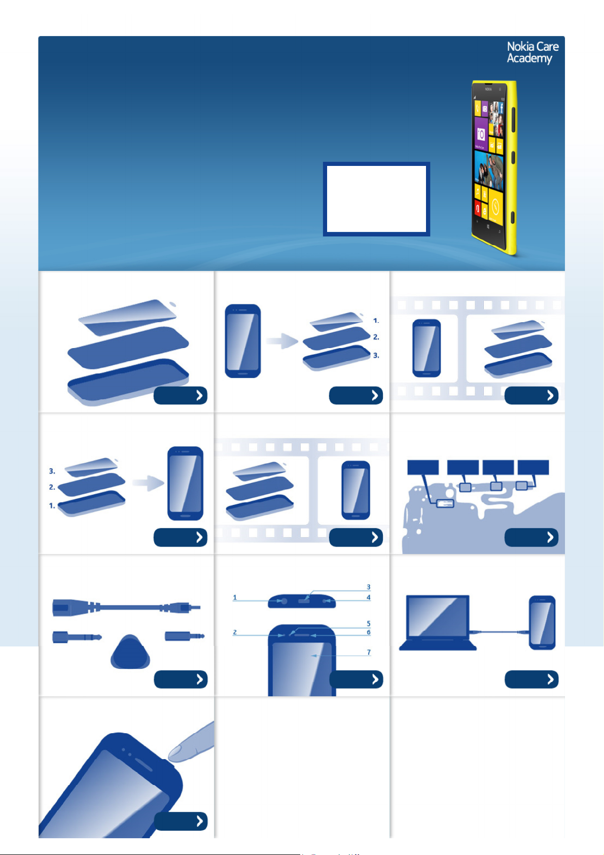
Nokia Lumia 1020
RM-877
Key features
1.5 GHz Qualcomm dual-core processor
2 GB RAM and 32 GB of internal storage
4.5" AMOLED Puremotion HD+ display
41 Mpix PureView camera with OIS
2G / 3G / 4G LTE connectivity
Version 2.0
Exploded view Disassembly steps Disassembly video
Check the repair
policy before
performing any
mechanical repair
on Service Level
1&2!
Mor
Mor
Assembly steps Assembly video Solder components
Mor
Mor
Service devices Product controls and interfaces Service concept
Mor
Mor
Mor
Mor
Mor
Phone reset
Mor
©2013 Nokia | Nokia Internal Use only | All Rights Reserved.
Service Manual Level 1 and 2
Nokia Lumia 1020
RM-877
Version 2.0
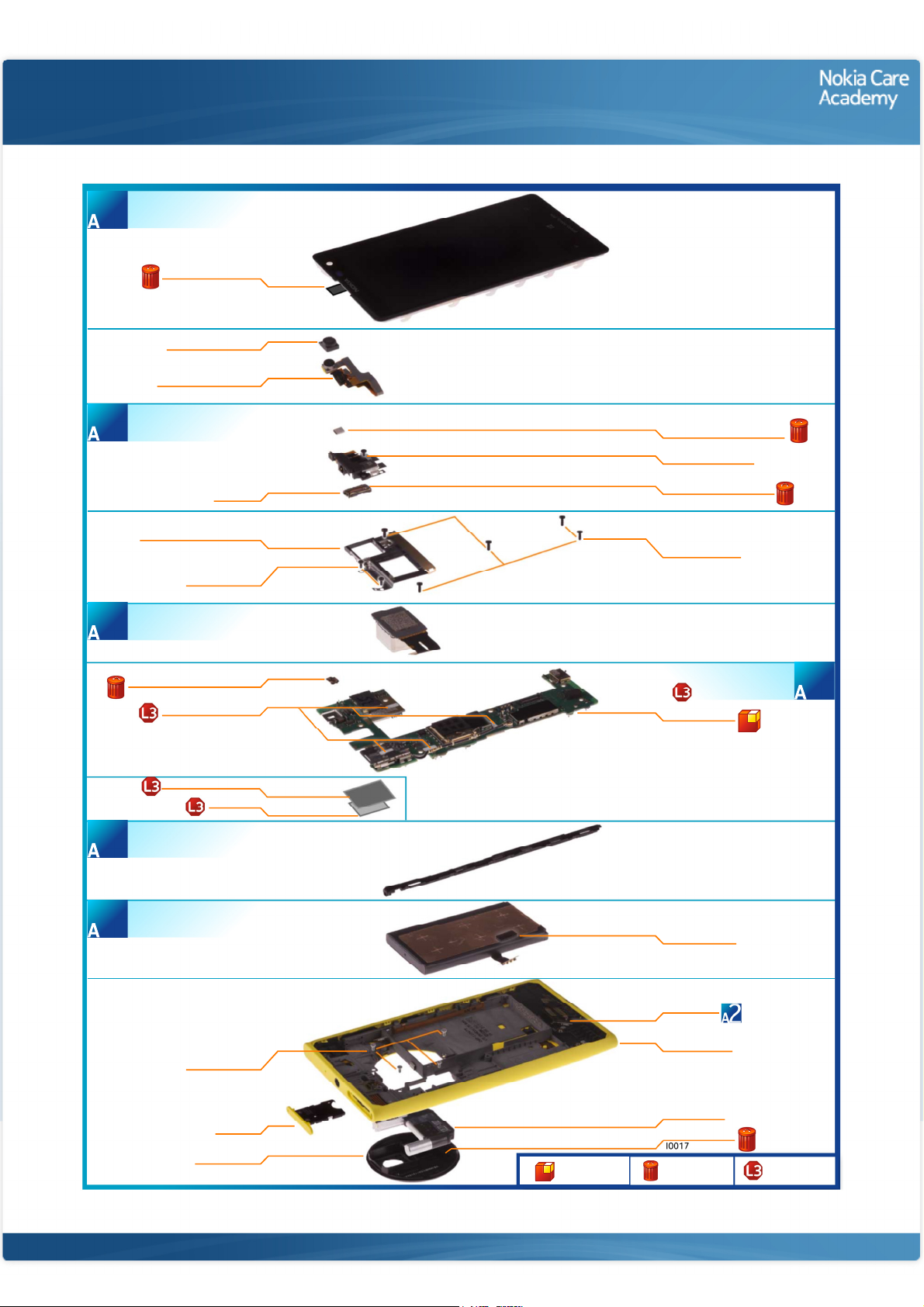
WINDOW ASSEMBLY
(I0001)
1
Exploded view
SENSOR SEALING TAPE
2ND CAMERA GASKET
2ND CAMERA ASSEMBLY
AV ASSEMBLY
(I0005 - I0007)
3
BATTERY HOLDER ASSEMBLY
CAMERA ASSEMBLY
5
2ND CAMERA GROUNDING PAD
WATER INGRESS LABEL
I0001
I0013
I0012
EARPIECE
I0005
I0009
SCREW TORX+
SIZE 5 M1.4 x 3.0
I0011
I0003
AV FRAME GROUNDING FOAM
I0006
SCREW TORX+ SIZE 5
EARPIECE HOLDER GASKET
I0007
SCREW TORX+
SIZE 6 M1.6 X 3.5
I0010
LIGHT SWAP PACKAGE
LIGHT SWAP PWB
I0002
(I0002 - I0004)
2
LABEL TRAY ASSEMBLY
LOCKING RAIL ASSEMBLY
6
BATTERY ASSEMBLY
(I0008)
4
SIZE 4 M1.4 x 2.5
I0018
TYPE LABEL
I0019
SCREW TORX+
I0014
SIM TRAY
I0021
CAMERA DECO
I0016
Only available
as assembly
BATTERY GASKET
I0008
USB GASKET
I0004
BODY ASSEMBLY
I0020
XENON FLASH
I0015
FLASH ADHESIVE
Not reuseable
after removal
Repair/swap
only in level 3
©2013 Nokia | Nokia Internal Use only | All Rights Reserved.
Service Manual Level 1 and 2
Nokia Lumia 1020
RM- 877
Version 2.0
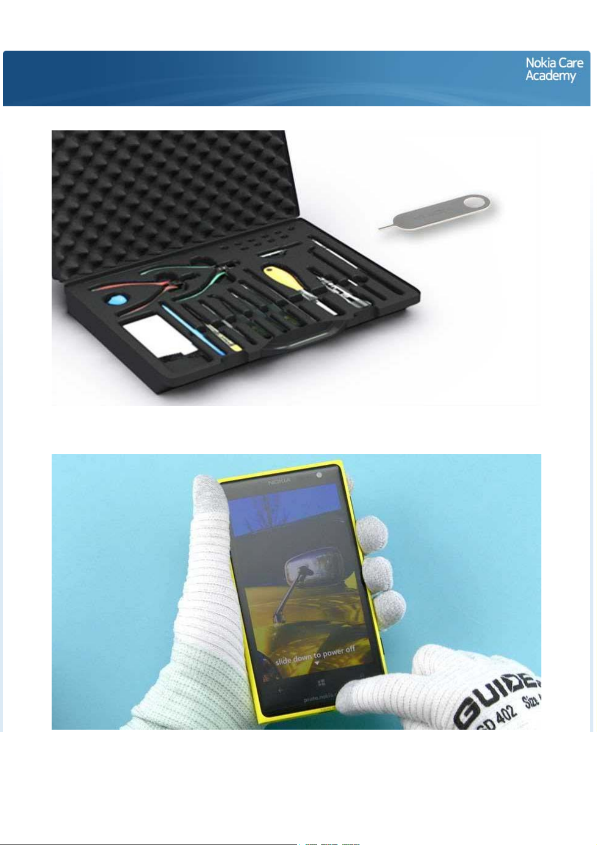
Disassembly steps
1) For disassembling you need the Nokia Standard toolkit version 2. You will also need the SIM door key.
2) The power must be off during the disassembly procedure.
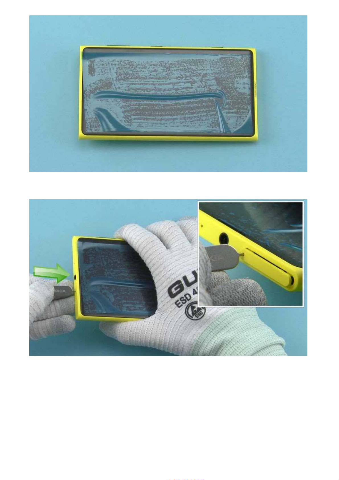
3) Protect the DISPLAY with protective film.
4) Release the SIM TRAY with the SIM door key.
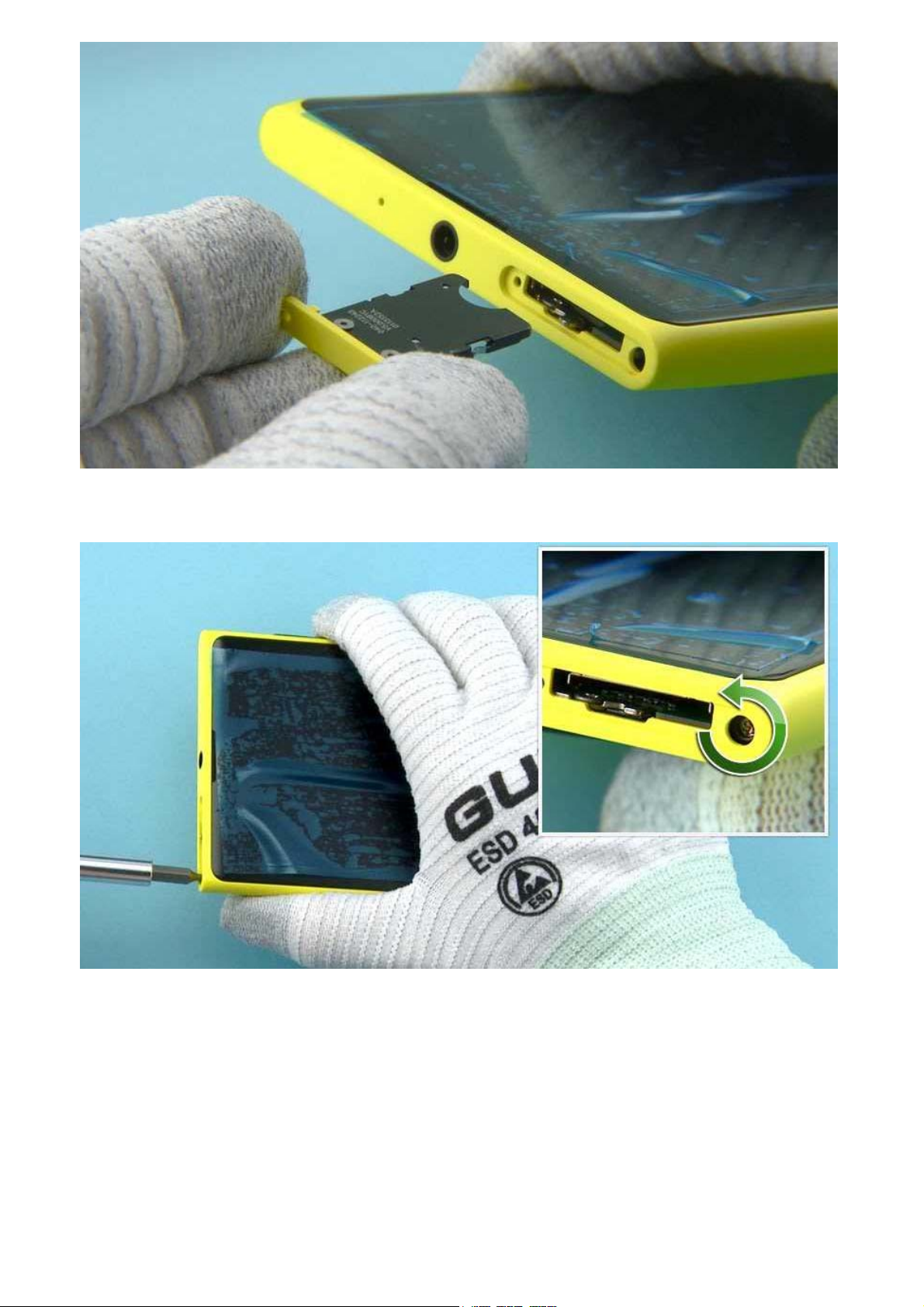
5) Pull the SIM TRAY out.
6) Unscrew the TORX+ size 4 LOCKING RAIL SCREW. Open the screw 8 full turns.
Loosen the screw very slowly and be careful not to break the LOCKING RAIL ASSEMBLY.
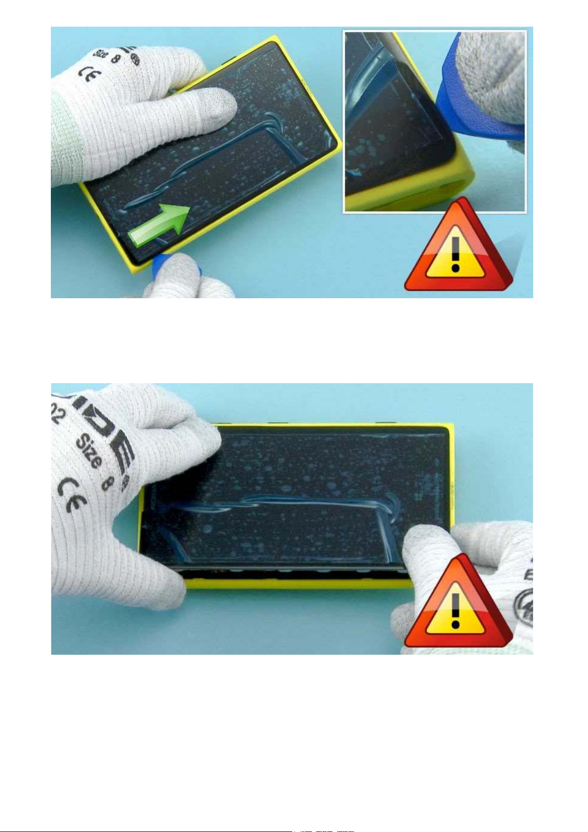
7) Use the SRT-6 to detach the DISPLAY. Release the left side of the device by sliding the SRT-6 as
shown.
Be careful not to damage any components or the flexes underneath the DISPLAY.
8) Carefully lift the left side of the DISPLAY to gain access to the connectors.
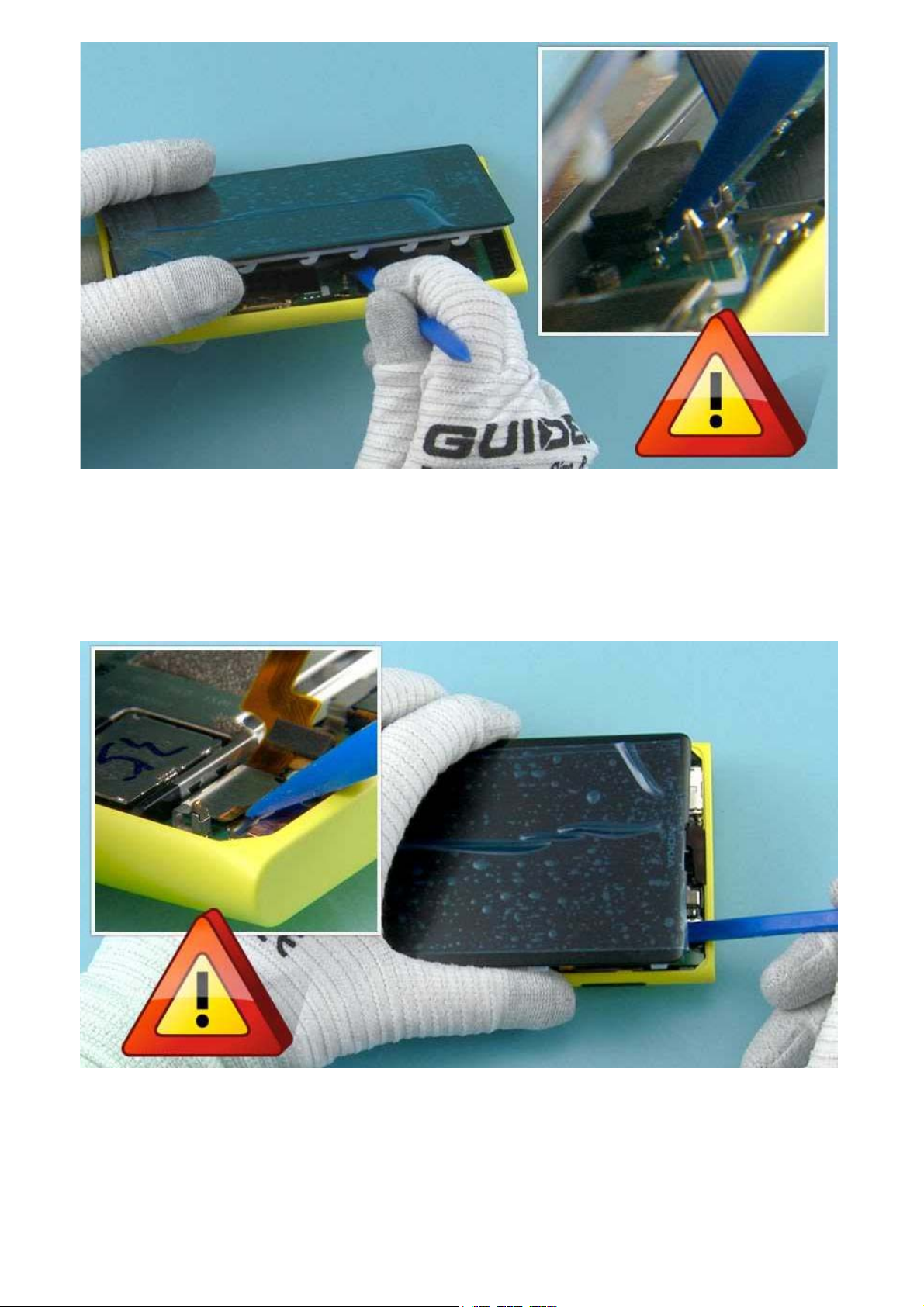
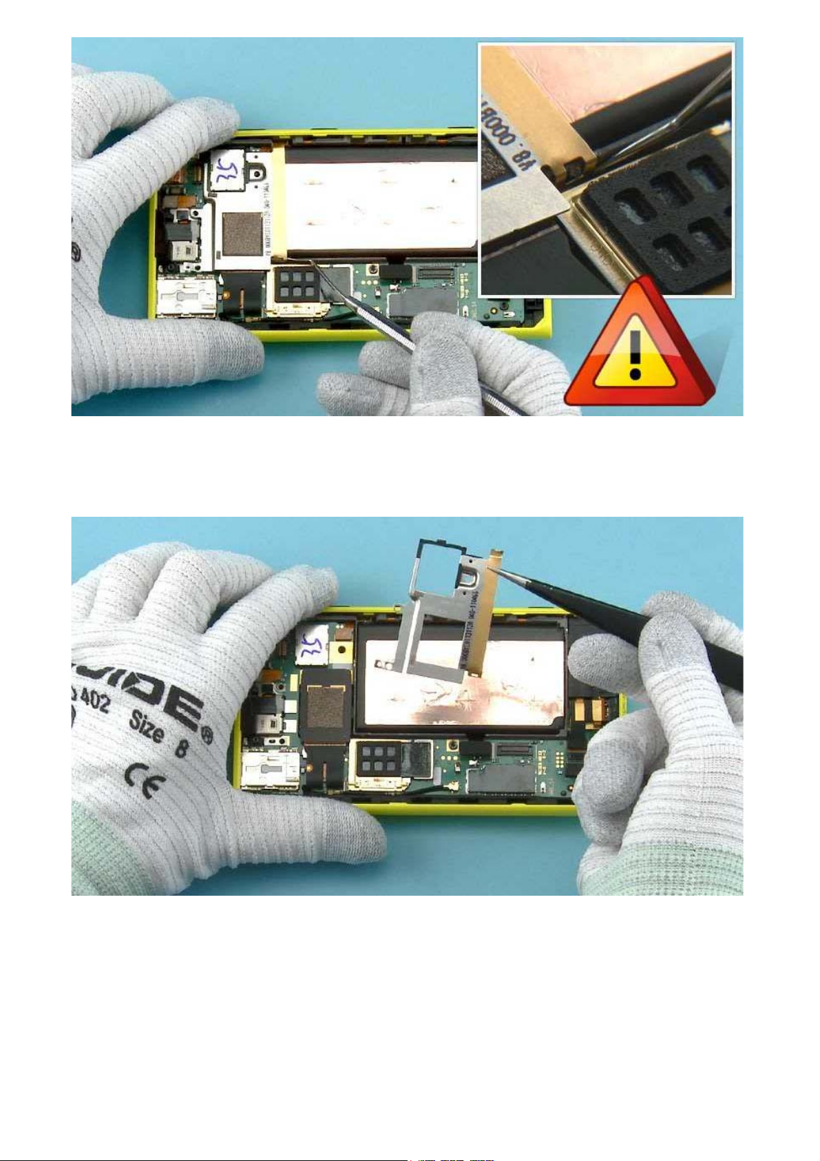
9) Use the SS-93 to open the BATTERY CONNECTOR.
Be careful not to damage the connector or any nearby components.
NOTE: The opening order of the connectors is mandatory to minimize the risk of battery current short
circuits.
10) Use the SS-93 to open the 2nd CAMERA FLEX CONNECTOR.
Be careful not to damage the connector or any nearby components.
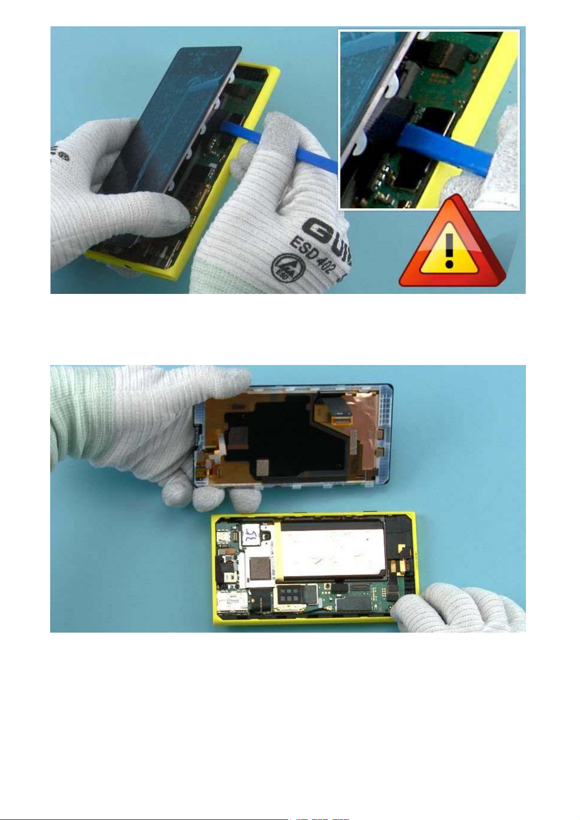
11) Use the SS-93 to open the DISPLAY CONNECTOR.
Be careful not to damage the connector or any nearby components.
12) The DISPLAY can now be separated.
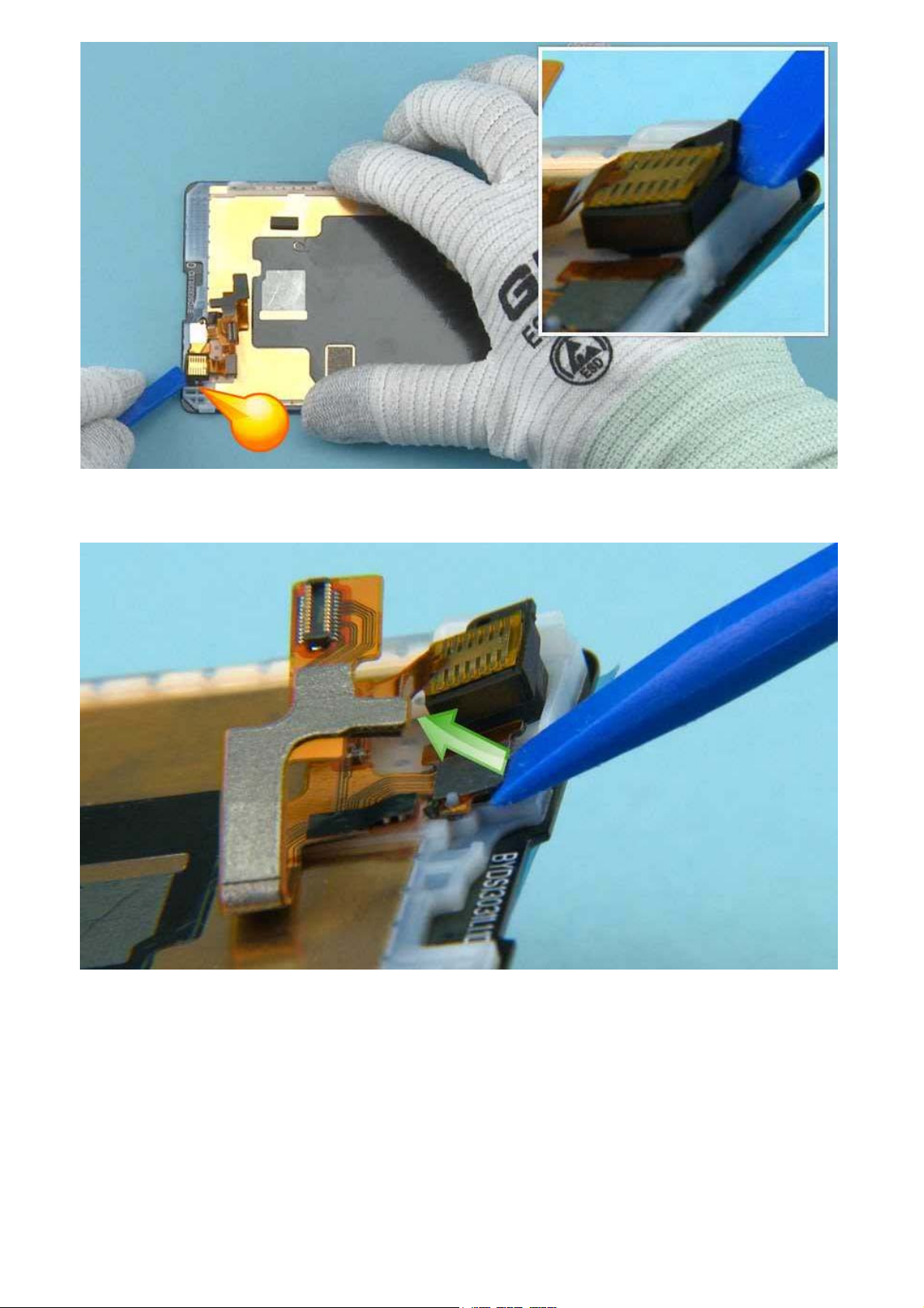
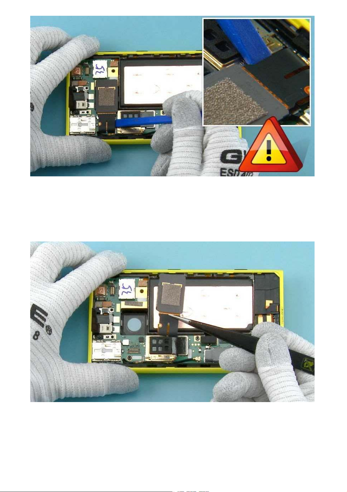
13) Start releasing the 2nd CAMERA ASSEMBLY with the SS-93 from the shown place.
14) Detach the SENSOR by lifting it with the SS-93 as shown.
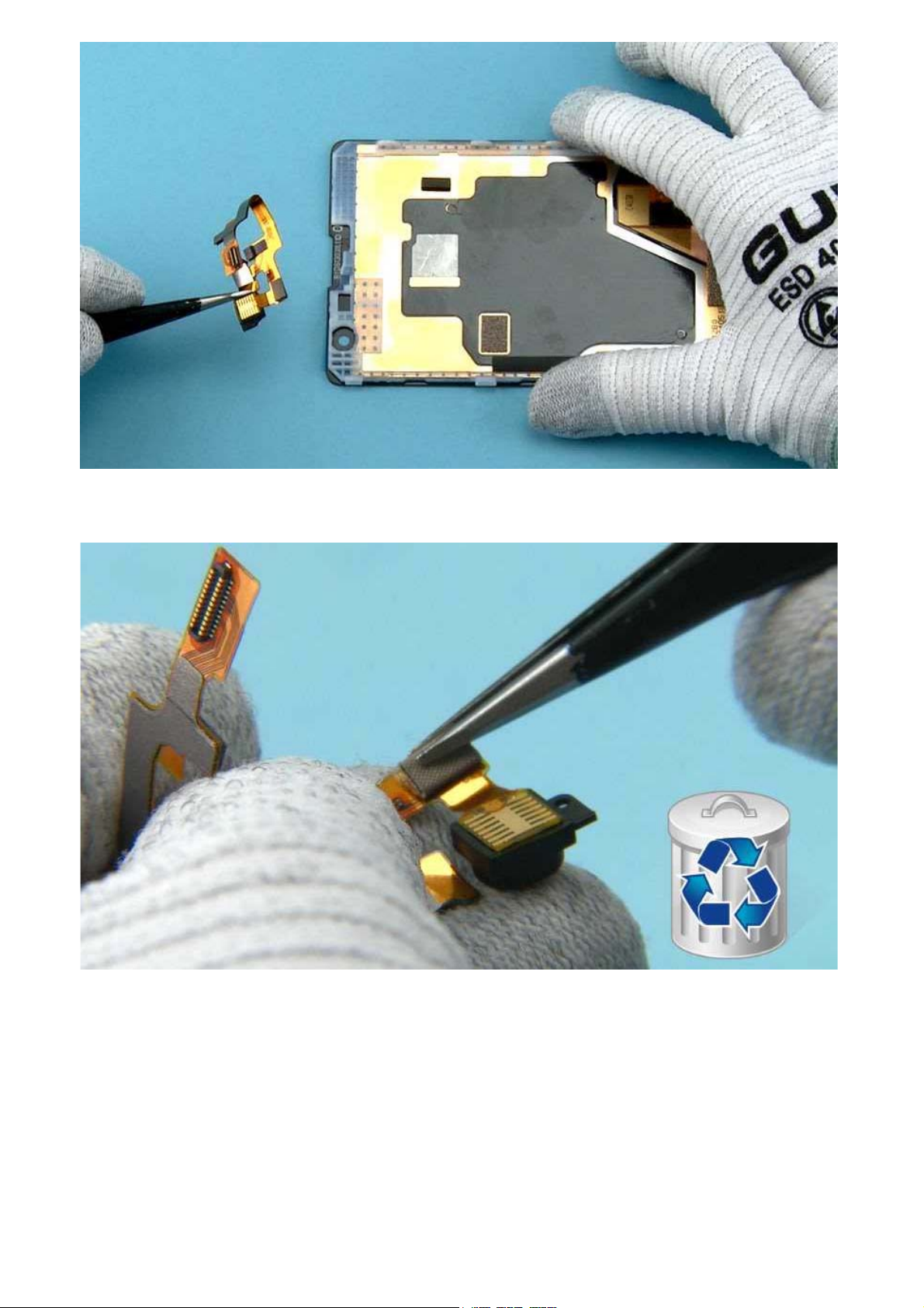
15) Remove the 2nd CAMERA ASSEMBLY with tweezers.
16) Use tweezers to remove the 2nd CAMERA GROUNDING FOAM. Do not use it again. Discard it.
17) Use tweezers to detach the 2nd CAMERA GASKET.
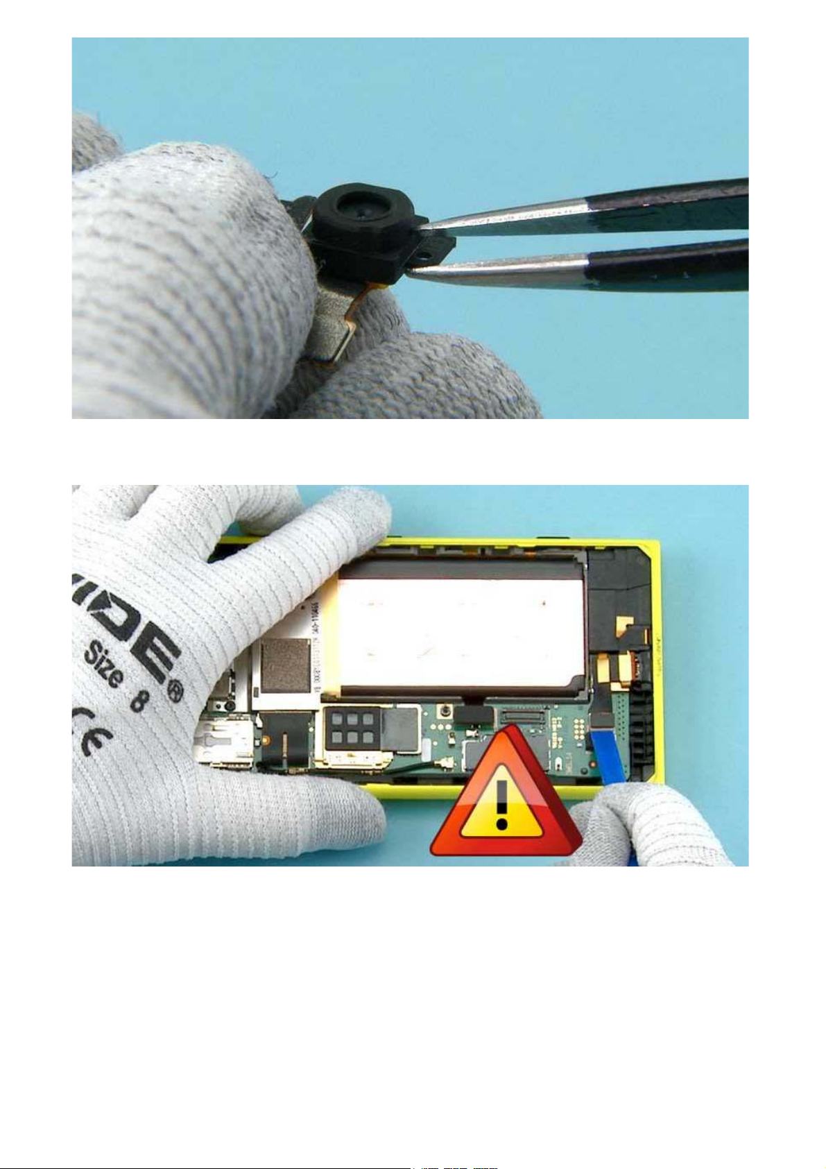
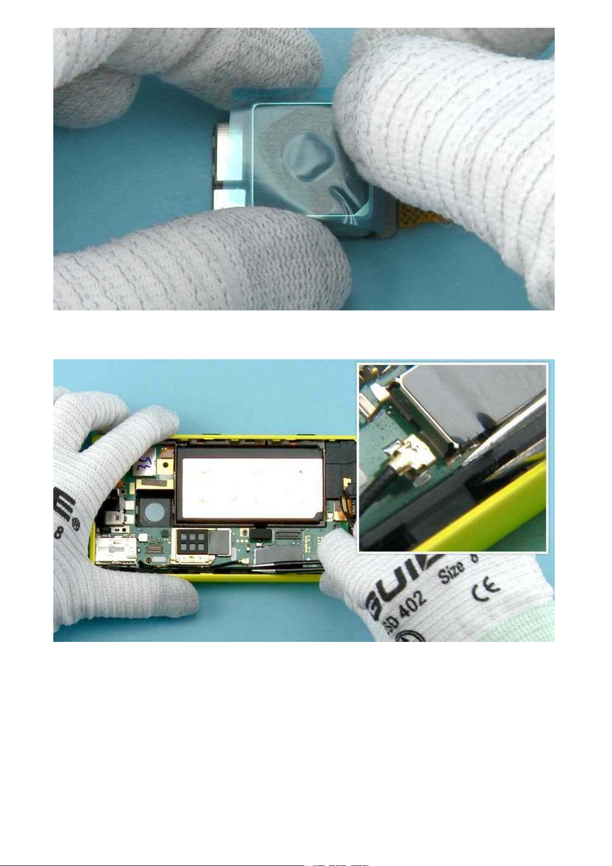
18) Use the SS-93 to open the USB CONNECTOR.
Be careful not to damage the connector or any nearby components.
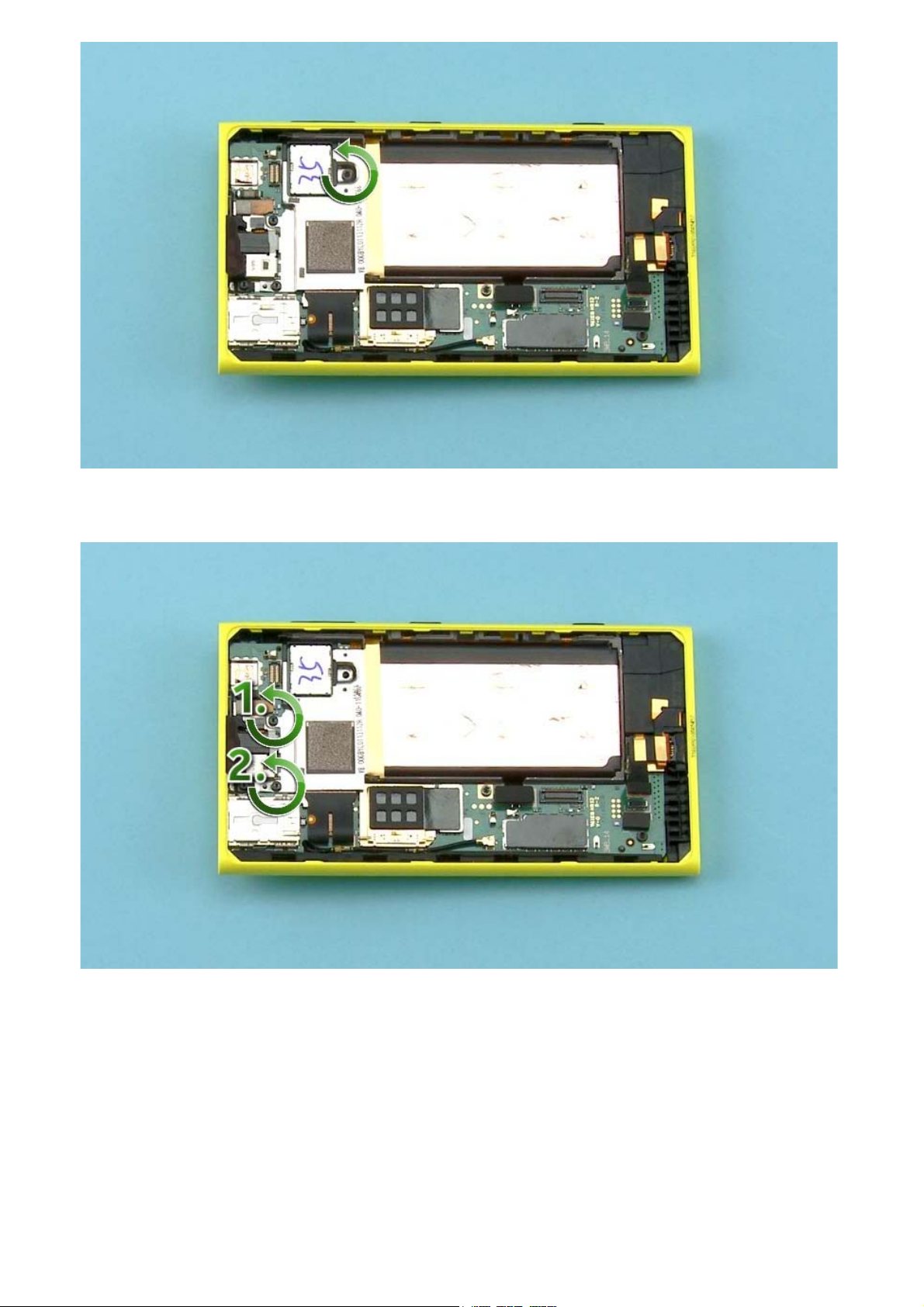
19) Unscrew this TORX+ size 6 screw.
20) Unscrew the two TORX+ size 5 screws in the order shown.
21) Use the dental tool to release the snaps holding the BATTERY HOLDER.
Be careful not to injure yourself with the sharp end of the dental tool.
22) Use tweezers to remove the BATTERY HOLDER.
23) Open the CAMERA CONNECTOR with the SS-93.
Be careful not to damage the connector or any nearby components.
NOTE: The surface on the back of the CAMERA is very thin ceramic. To avoid damaging it do not touch or
push the back of the camera.
24) Use tweezers to lift the CAMERA.
25) Protect the CAMERA LENS with protective film.
26) Use tweezers to detach the LOCKING RAIL.
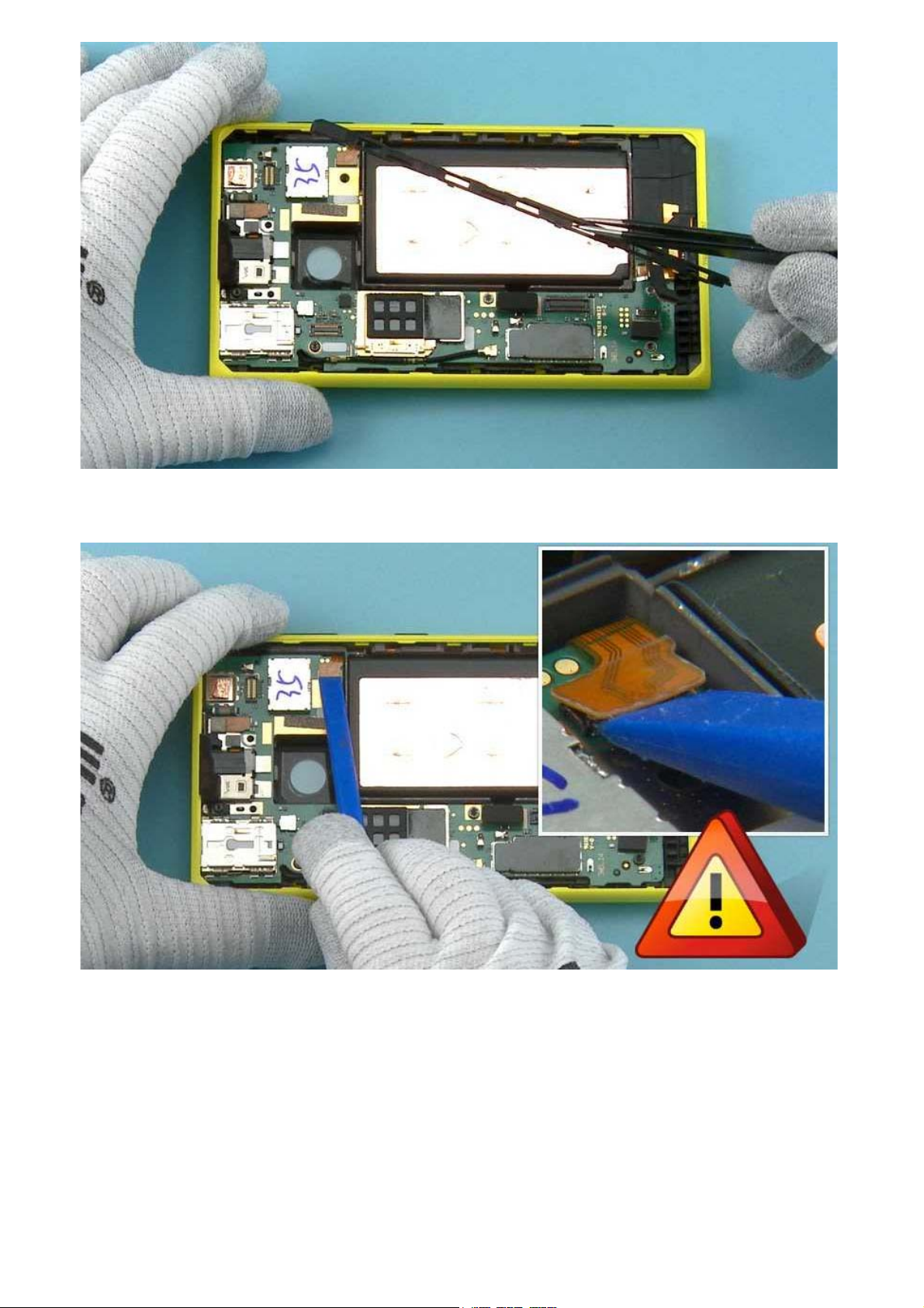
27) Remove the LOCKING RAIL.
28) Use the SS-93 to open the SIDE KEY FLEX CONNECTOR.
Be careful not to damage the connector or any nearby components.
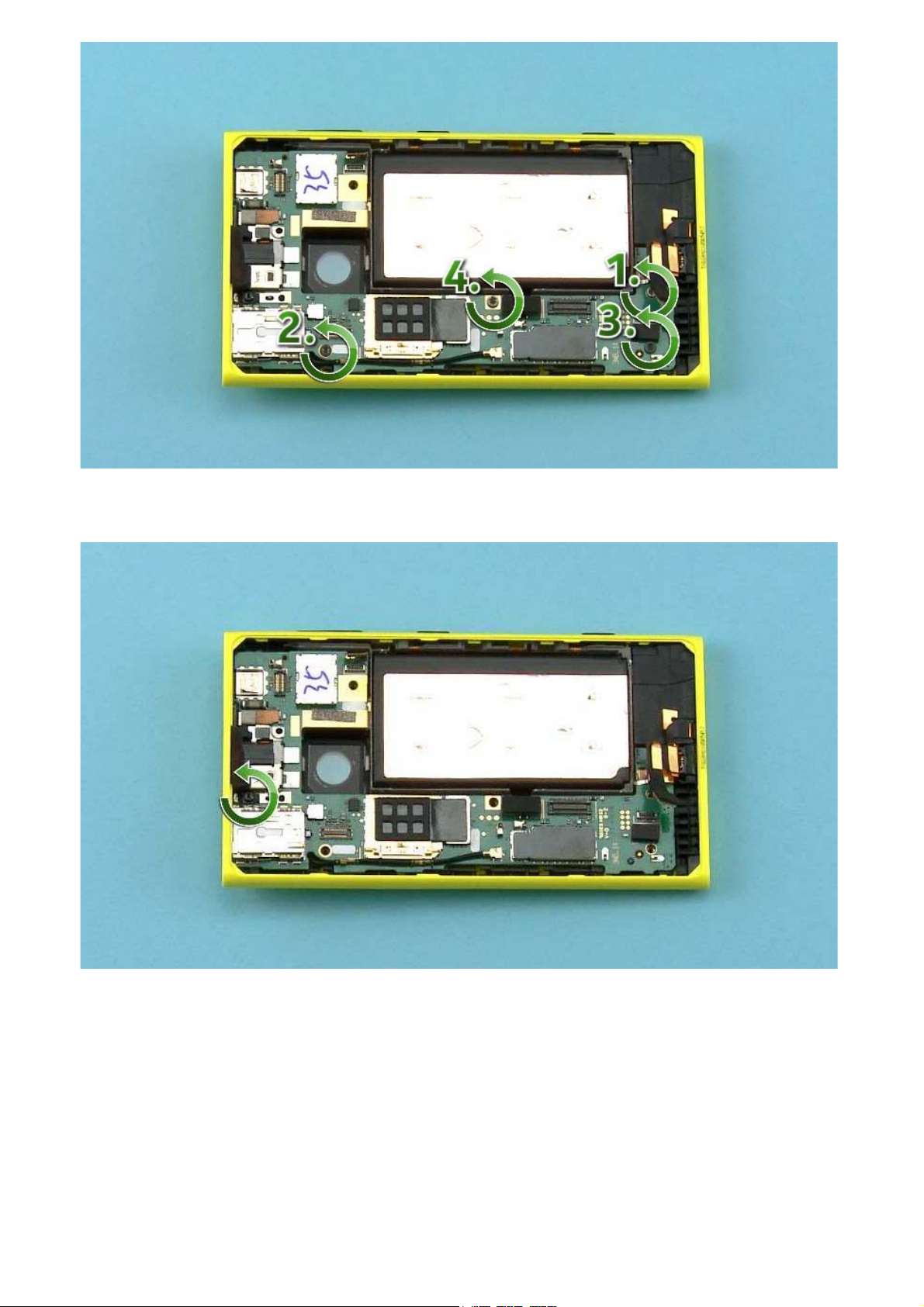
29) Unscrew the four TORX+ size 6 screws in the order shown.
30) Unscrew this TORX+ size 5 screw.
 Loading...