

Page 1

TransTalk®9000
Digital Wireless System
MD W 9040 Wireless Pocket Phone
Installation, Troubleshooting, and Use
503-801-190
Comcode 108594409
Issue 1
May 2000
Page 2

Copyright © 1997, 1998 by Lucent Technologies. All rights reserved.
For trademark, regulatory compliance, and related legal information, see the
copyright and legal notices section of this document.
Page 3

Copyright and Legal Notices
Copyright
Notice
Federal
Communications
Commission and
Industry Canada (IC)
Information
Security
Copyright © 2000 by Luce nt Technologies.
All rights reserved. Printed in U.S.A.
Every effor t has been made to e nsure that the information in thi s book was complete
and accurate at the time of printing. I nformation, however, is subject to change. The
pictures in this book are for illustrative purposes; your actual hardware may look
slightly different.
This document was prepared by the Product Publications Department of the Global
Learning Solutions Division of Lucent Techn ologies. U.S. offices are located in
Denver, CO; Columbus , OH; Holm del, NJ; and Basking Ridge, NJ.
For details, see Appendix B.
Toll fraud, the unauthorized use of your telecom m unications system by an
unauthorized party (for example, persons other than your company’s employees,
agents, subcontractors, or persons working on your company’s behalf), can result in
substantial additional charges for your telecommunications services. You are
responsible for the security of your system. There may be a risk of toll fraud
associated with your telecommunicati ons system. You are also responsible for
programming and configuring your equipment to pre vent unauthorized use. Your
system administrator should read all docum ents provided with this product to fully
understand the fea tures that can introduce the risk of toll fraud and the steps that can
be taken to reduce that risk. Lucent Technologies does not warrant that this product is
immune from or will pre vent u naut horize d use of common -carrie r tel ecommuni cati on
services or facilities accessed through or connected to it. Lucent Te chnologies will
not be responsible for any charges that result from such unautho rized use.
Trademarks
DEFINITY, MERLIN, MERLIN LEGEND, PARTNER, and TransTalk are
registered trademarks of Lucent Technologies; MERLIN MAGIX is a trademark of
Lucent Technologies. Supra is a registered trademark of Plantronics, Inc.
Warranty
Ordering Informat ion
Lucent Technologies provides a limited warranty for this product; s ee Appendix A.
The order number for this book is 503-801-190. To order additional copies of these
reference materials, call 1-800-457-1235 or 317-322-6791. To order parts and
accessories, see Appendix D, “Ordering Replacement and Optional Parts.”
Customer Support
Follow the procedure you normally use to obtain support for your communications
system.
Outside the continental U.S., contact your Lucent Technologies Representative or
local Auth or ized Dealer.
MDW 9040 Wireless Pocket Phone Installation, Troubleshooting, and Use,
503-801-190 Issue 1, May 2000 ii
Page 4

Copyright and Legal Notices Important Safety Instructions
Important Safety Instructions
This book contains instructions related to safety label s on the product:
!
WARNING:
WARNING indicates the presence of a hazard that can cause severe or
fatal personal injury If the hazard is not avoided.
!
CAUTION:
CAUTION indicates the presence of a hazard that will or can cause
minor personal injury or property dam age if not avoided.
This phone is designed to provide troubl e-free performance without any special maintenance procedures. To
reduce the risk of acci dental damage:
•
Keep the phone in an are a free of dust, smoke, and moisture ; do not block the air
vents by placing objects on top of the radio module.
•
Do not place the phone or battery charger near a heating duct, radiator, or other
heat source, and do not drop or expose it to excessive shock or vibration.
•
Unplug the battery charger, radio module, or ca rrier if its power cord is damaged,
if liquid is spilled i nto it, or i f its housing becomes crack ed or otherwise damaged.
•
To clean your phone, wipe the outside housing with a soft, dust-free cloth. If
absolutely necessary, you may use a cloth slightly dampened with a mild soapand-water solu tion. Dry quickly with a soft clot h.
!
CAUTION:
Your phone contains sensitive electronic parts. Never submerge it in
any kind of liquid, and never use liquid or aerosol cleaners, detergents,
alcohols, solvents, abrasive cleaners, or an excessive amount of water
when cleaning the housing and faceplate. To do so could result in
irreparable damage.
!
WARNING:
Installation of this equipment for In-Range Out of Building (IROB)
conditions requires the use of protectors. See the documentation that
came with your communications system for more information.
!
CAUTION:
This equipment is for installation on Lucent Technologies PARTNER,
PARTNER Plus, PARTNER II, PARTNER Advanced Communications
System, MERLIN, MERLIN Plus, MERLIN II, MERLIN LEGEND, MERLIN
MAGIX, and DEFINITY Communications Systems only.
For your own s afe ty, follow these rules before or while using your phone:
•
Befor e us ing this product, read and understand all warnings and instructions.
•
Observe all warnings and instructio ns marked on this product.
MDW 9040 Wireless Pocket Phone Installation, Troubleshooti ng, and Use,
503-801-190iii Issue 1, May 2000
Page 5

Important Safety Instructions Copyright and Legal Notices
•
Do not use this phone in the vicinity of a suspect ed gas leak. This pr oduct is not
approved for us e in areas labeled by the Occ upational Safety and Healt h
Administration (OSHA) as “explosive environments.” Only “Explosive
Atmosphere Telephones ” may be used in such hazardous environments.
•
This pro d u ct should be serviced by a quali fied ser v ice center when service or
repair work is required. Do not open the product or push objects through housing
slots. There are no user-serviceable components inside.
•
Use only the type of battery pack shipped with this product or sold as an optional
part. (See “Ordering Replacement and Optional Parts” in Chapter 4.)
!
WARNING:
Do not burn or pun ct ur e the bat te r y pack. Do not di spose of the battery
pack in household garbage. For information about recycling or proper
disposal, consult your local solid waste (garbage) collection or disposal
organization.
Exposure to Radio
Frequency Energy
Cardiac Pacemakers
and Life-Support
Equipment
Hearing Aid
Compatibility
The design of your wirele s s telephone complies with the latest Institute of Elec trical
and Electronic Engineers (IEEE) and the American National Standards Institute
(ANSI) safety levels with respect to human exposure to RF energy.
!
CAUTION:
The MDW 9040 handset is a radio transceiver device. It is recommended
that the handset not be placed within 6 inches of a pacemaker.
It is recommended that standard acceptance test procedures be followed prior to
operating t his e quip ment in pr oxim ity of lif e-supp ort equi pment .Until more i s known,
the FDA suggests that people with pacemakers may want to take some simple
precautions when using or carrying digital wireless telephone s. The y sh ould ensure
that th e re is ample dist an ce betw ee n the digital wireless tele p h on e and the
pacemaker—by not placing the phone next to t he pacemaker impl ant (for example, in
a shirt or a coa t pocke t direc tly ove r th e pacemake r impla nt) when the p hone is on and
ready to rec eive a call and by holding it to the ear opp os ite the side of the body where
the pacemaker is implanted when using the phone. Th ey s hould consult their
physicians or medi cal de vice manu facture rs to de termine i f addi tional precau tions are
necessary.
The operation of inadequately shielded medical devices may be adversely affected
when a portable wireless tele phone is operat ing in cl ose pro ximit y. Use of an optiona l
headset would solve this problem.
Additional Safety
Instructions for
Installation Personnel
•
Install th e pr oduct to meet all envir onmental and electrical re quirements lis ted in
App endix C.
•
All wiring that connects to this equipment and becom es part of the building
wiring must be a minimum of CLASS 2 or UL (Underwriters Laboratories)
Listed Communications cable.
•
Do not install telephone wiring during a lightn ing s torm.
MDW 9040 Wireless Pocket Phone Installation, Troubleshooting, and Use,
503-80 1-190 Issue 1, May 2000 i v
Page 6

Copyright and Legal Notices Important Safety Instructions
•
Do not install telephone jacks in a wet location unless the jack is specifically
designed for wet locations. Never touch telephone wires or terminals that are not
insulated unless the telephone line has been disconnected at the network interface.
•
Install this pr oduct in a protected location where no one can step on or trip over
power cords and telephone line cords. Do not place objects on the c ords that may
cause damage or abrasion.
•
IS THERE ONE? ---->
IF SO, COMCODE,
PLEASE.
Use only the power supply (Comcode xxxxxxxxx) shipped with this product for
the battery charger.
•
Use only the auxiliary po we r supply (Comc ode
108212952
) specified for use with
this product .
MDW 9040 Wireless Pocket Phone Installation, Troubleshooti ng, and Use,
503-801-190v Issue 1, May 2000
Page 7

Page 8

Contents
Safety Instructions iii
1 Introduction 1
About the MDW 9040 Pocket Phone. . . . . . . . . . . . . . . . . . . . . . . . . . . . . . . . . . . . . . . . . . . . . . 1
Privacy Information . . . . . . . . . . . . . . . . . . . . . . . . . . . . . . . . . . . . . . 1
Where Can You Use Your Pocket Phone? . . . . . . . . . . . . . . . . . . . . . . . . . . 1
Parts List . . . . . . . . . . . . . . . . . . . . . . . . . . . . . . . . . . . . . . . . . . . 2
Spare Battery Pack and Headset. . . . . . . . . . . . . . . . . . . . . . . . . . . . . . . 2
2 Installing and Registering the MDW 9040 Pocket Phone 3
Overview. . . . . . . . . . . . . . . . . . . . . . . . . . . . . . . . . . . . . . . . . . . . . . . . . . . . . . . . . . . . . . . . . . . 3
Installation Procedures for the DRM . . . . . . . . . . . . . . . . . . . . . . . . . . . . . . . . . . . . . . . . . . . . . . 3
About the Dual Radio Module . . . . . . . . . . . . . . . . . . . . . . . . . . . . . . . . 4
Positioning a DRM . . . . . . . . . . . . . . . . . . . . . . . . . . . . . . . . . . . . . . 6
Single-Zone and Dual-Zone Configuration . . . . . . . . . . . . . . . . . . . . . . . . . . 7
Auxiliary Power and Switch Wiring . . . . . . . . . . . . . . . . . . . . . . . . . . . . . . 7
A Quick Reference Procedure for Handset Registration . . . . . . . . . . . . . . . . . . . 9
Installing a Single DRM for Single-Zone Operation. . . . . . . . . . . . . . . . . . . . . .10
Installing Multiple DRMs for Single-Zone Operation . . . . . . . . . . . . . . . . . . . . .11
Installing Multiple DRMs in a Dual-Zone Configuration. . . . . . . . . . . . . . . . . . . .13
Setting Up and Registering the Handset. . . . . . . . . . . . . . . . . . . . . . . . . . . . . . . . . . . . . . . . . . 13
Inser ting the Handset’s Battery Pack . . . . . . . . . . . . . . . . . . . . . . . . . . . . .13
Performing the Registration. . . . . . . . . . . . . . . . . . . . . . . . . . . . . . . . . .14
Mapping the MDW 9040 to the Correct
Communications System. . . . . . . . . . . . . . . . . . . . . . . . . . . . . . . . . . . . . . . . . . . . . . . . . . . . 16
Filling Out the Handset Label . . . . . . . . . . . . . . . . . . . . . . . . . . . . . . . . .17
Other Handset Configuration Options . . . . . . . . . . . . . . . . . . . . . . . . . . . . . . . . . . . . . . . . . . . . 18
Installin g and Using the Battery C ha rg er . . . . . . . . . . . . . . . . . . . . . . . . . . . . . . . . . . . . . . . . . 19
Battery Charger Features. . . . . . . . . . . . . . . . . . . . . . . . . . . . . . . . . . .19
Positioning the Battery Charger. . . . . . . . . . . . . . . . . . . . . . . . . . . . . . . .20
Installing the Battery Charger. . . . . . . . . . . . . . . . . . . . . . . . . . . . . . . . .21
Inserting the Handset into the Batter y Charger’s Handset Cradle . . . . . . . . . . . . . .21
Extending Battery Life . . . . . . . . . . . . . . . . . . . . . . . . . . . . . . . . . . . .22
Inserting a Battery Pack into the Spare Battery Compartment . . . . . . . . . . . . . . . . . . . . . . . . . 24
3 Using the MDW 904 0 Pocket Phone 25
Important Safety Instructions. . . . . . . . . . . . . . . . . . . . . . . . . . . . . . . . . . . . . . . . . . . . . . . . . . . 25
About the Handset. . . . . . . . . . . . . . . . . . . . . . . . . . . . . . . . . . . . . . . . . . . . . . . . . . . . . . . . . . . 25
Handset Features . . . . . . . . . . . . . . . . . . . . . . . . . . . . . . . . . . . . . .26
The Handset Display . . . . . . . . . . . . . . . . . . . . . . . . . . . . . . . . . . . . .27
MDW 9040 Wireless Pocket Phone Installation, Troubleshooting, and Use,
503-801-190 Issue 1, May 2000
vii
Page 9

Contents
Setting or Changing the Handset Settings. . . . . . . . . . . . . . . . . . . . . . . . . . . . . . . . . . . . . . . . . 31
Using the Configuration and Option Menus. . . . . . . . . . . . . . . . . . . . . . . . . 33
A Flowchart for the Configuration, Options, and Test Mode Display Screens. . . . . . . . 35
Using Local Test Mode . . . . . . . . . . . . . . . . . . . . . . . . . . . . . . . . . . . 36
Using Wireless Test Mode . . . . . . . . . . . . . . . . . . . . . . . . . . . . . . . . . 36
Using Handset Features . . . . . . . . . . . . . . . . . . . . . . . . . . . . . . . . . . . . . . . . . . . . . . . . . . . . . . 4 0
“Waking Up” the Phone . . . . . . . . . . . . . . . . . . . . . . . . . . . . . . . . . . . 40
Placing a Call . . . . . . . . . . . . . . . . . . . . . . . . . . . . . . . . . . . . . . . . 41
Answering a Call . . . . . . . . . . . . . . . . . . . . . . . . . . . . . . . . . . . . . . 41
Manually Selecting a Line or Programmed Button . . . . . . . . . . . . . . . . . . . . . 41
Preselecting a Line . . . . . . . . . . . . . . . . . . . . . . . . . . . . . . . . . . . . . 4 2
Accessing Certain Voice Mail Systems
with a DEFINITY System . . . . . . . . . . . . . . . . . . . . . . . . . . . . . . . . . 42
Using a Headset . . . . . . . . . . . . . . . . . . . . . . . . . . . . . . . . . . . . . . 42
Programming Switch-Related Features. . . . . . . . . . . . . . . . . . . . . . . . . . . 43
The Handset Antenna. . . . . . . . . . . . . . . . . . . . . . . . . . . . . . . . . . . . 44
Carrying Your Pocket Phone . . . . . . . . . . . . . . . . . . . . . . . . . . . . . . . . . . . . . . . . . . . . . . . . . . .44
4 Troubleshooting 47
Overview . . . . . . . . . . . . . . . . . . . . . . . . . . . . . . . . . . . . . . . . . . . . . . . . . . . . . . . . . . . . . . . . . .47
Installation Problems . . . . . . . . . . . . . . . . . . . . . . . . . . . . . . . . . . . . . . . . . . . . . . . . . . . . . . . . . 48
Handset Problems . . . . . . . . . . . . . . . . . . . . . . . . . . . . . . . . . . . . . . . . . . . . . . . . . . . . . . . . . . . 48
Battery Problems. . . . . . . . . . . . . . . . . . . . . . . . . . . . . . . . . . . . . . . . . . . . . . . . . . . . . . . . . . . . 50
Voice Quality Problems . . . . . . . . . . . . . . . . . . . . . . . . . . . . . . . . . . . . . . . . . . . . . . . . . . . . . . . 5 1
Range Problems . . . . . . . . . . . . . . . . . . . . . . . . . . . . . . . . . . . . . . . . . . . . . . . . . . . . . . . . . . . . 53
Battery Charger Problems . . . . . . . . . . . . . . . . . . . . . . . . . . . . . . . . . . . . . . . . . . . . . . . . . . . . .53
5 MDW 9040 Pocket Phone Compatibility 57
Programming and Call Handling Instructions. . . . . . . . . . . . . . . . . . . . . . . . . . . . . . . . . . . . . . . 57
. . . . . . . . . . . . . . . . . . . . . . . . . . . . . . . . . . . . . . . . . . . . . . . 58
Programming Features for PARTNER, MERLIN, and MERLIN LEGEND System s. . . . . 58
Communications System Compatibility . . . . . . . . . . . . . . . . . . . . . . . . . . . . . . . . . . . . . . . . . . . 59
PARTNER Systems . . . . . . . . . . . . . . . . . . . . . . . . . . . . . . . . . . . . . 59
MERLIN Systems . . . . . . . . . . . . . . . . . . . . . . . . . . . . . . . . . . . . . . 61
MERLIN MAGIX System . . . . . . . . . . . . . . . . . . . . . . . . . . . . . . . . . . 64
DEFINITY Systems . . . . . . . . . . . . . . . . . . . . . . . . . . . . . . . . . . . . . 66
Appendix A: Warranty and Repair Information 69
Lucent Technologies Limited Warranty and Limitation of Liability . . . . . . . . . . . . . . . . . . . . . . . 69
Limitation of Liability. . . . . . . . . . . . . . . . . . . . . . . . . . . . . . . . . . . . . 70
Repair Information. . . . . . . . . . . . . . . . . . . . . . . . . . . . . . . . . . . . . . . . . . . . . . . . . . . . . . . . . . . 70
In-Warranty Repairs. . . . . . . . . . . . . . . . . . . . . . . . . . . . . . . . . . . . . 70
Post-Warranty Repairs . . . . . . . . . . . . . . . . . . . . . . . . . . . . . . . . . . . 70
viii
Issue 1, May 2000
MDW 9040 Wireless Pocket Phone Installation, Troubleshooting, and Use,
503-801-190
Page 10

Contents
Appendix B: Regulatory Information 71
FCC Part 15 Rules . . . . . . . . . . . . . . . . . . . . . . . . . . . . . . . . . . . . . . . . . . . . . . . . . . . . . . . . . . 71
IC RSS-210 Compliance . . . . . . . . . . . . . . . . . . . . . . . . . . . . . . . . . . . . . . . . . . . . . . . . . . . . . . 71
Hearing Aid Compatibility . . . . . . . . . . . . . . . . . . . . . . . . . . . . . . . . . . . . . . . . . . . . . . . . . . . . . 71
Appendix C: Specifications 73
Appendix D: Ordering Replacement and Optional Parts 77
MDW 9040 Wireless Pocket Phone Installation, Troubleshooting, and Use,
503-801-190 Issue 1, May 2000
ix
Page 11

Page 12

About the MDW 9040 Pocket Phone
1 Introduction
The MDW 9040 Pocket Phone has been designed to wor k with Lucent Technologies communi cations systems
including PARTNER
The MDW 9040 is different from its predecessors in several different ways:
®
, MERLIN®, MERLIN MAGIX™ and DEFINITY® switches).
IMPORTANT NOTE: The MDW 9040 is NOT backward com p atib le with other
TransTalk systems; that is, it CANNOT be added to existing TransTalk systems
or used in the same coverage area as the MDW 9000, MDW 9010, MDW 9030,
or MDW 9031.
•
The base station to which the handset is connected is called a Dual-Radio
Module (o r D RM) because eac h module can support two handset s
simultaneously.
•
The DRM and the handset work toget her without a carrier backplane unit. The
DRM itself can be placed on a flat surface such as a shelf or table or mounted on
a wall.
•
In the past, one ba se station was shipped from the factory together with a handset
with the same serial code and registration number. Beginning with the
MDW 9040, the DRM and the handset are packaged se para tely, and the customer
will need to regist er ea ch hand set with the DRM with which it will communic at e.
Again, each DRM can communicate with two handsets.
Privacy Information
The MDW 9040 Pocket Phone is designed to protect the privacy and security of your voice conversation. The
phone uses continuously changing radio frequencies and digital encoding techniques to make it impossible for
eavesdropping to occur through the use of commercially available analog radio scanners.
Where Can You Use Your Pocket Phone?
The MDW 9040 Pocket Phone can be used in most typical office buildi ngs, warehouses, malls, and even outdoor
areas such as loading docks. The location of the DRM greatly aff ects the performance of the MDW 9040. Read
the “Positioning the DRM” section in Chapter 2 to determine the best place to install the DRM. Repeat the tests
several times with the DRM positioned in a different location each time. To perform the te sts, all you need is an
electrical outlet for the DRM and a charged battery pack in the handset.
MDW 9040 Wireless Pocket Phone Installation, Troubleshooting, and Use,
503-801-190 Issue 1,May 2000
1
Page 13

1
Introduction About the MDW 9040 Pocket Phone
Parts List
As noted above, the handset and the DRM are packaged separately. The following items come in the box with
these two pieces of equipment.
Note:
If it does not, call for customer su pport as describe d in the Cop yr ight and
Legal Notices at the beginning of this book.
The handset is packaged with the following:
•
The han d set
•
A standard battery pack
•
A belt clip
•
A battery charge r with wall-mountng lig ht
•
An 11-foot (3.4 meter) Power cord AC adapter for the battery charger
•
An 8-foot (2.4 meter) Telephone line cord
•
An 8-inch (0.5 meter) lanyard
•
A user quick reference guide
The DRM is packaged with the following:
•
The DRM
•
2 wall spacers
•
This installa tion and user’s manual
Additional Parts
The follo wing parts may be necessary, depending upon your installation.
Note:
This Kit of Parts is required only w h en a si ng le (stand-a l o n e) M DW
9040 Pocket Phone is installed.
•
A Radio Module 11-foot (3.4 mete r) P ower cord AC adapter
•
4 Rubber feet
•
2 Phil ips Head Wood Scr ew s
•
A Wall mounting plate
For information about ordering additional or replacement parts, see Appendix D, “Ordering Replacement and
Optional Parts.”
Spare Battery Pack and Headset
One nickel metal hydride battery pack, which provides up to three hours of talk time, comes with your
MDW 9040 Pocke t P hone. If you require additional phone usage, you can purchase an extended battery pack .
Although t hicker and he avier than the standard battery pa ck, the e xtended battery pack provides 8-9 hou rs of talk
time when fully charged. You can store the extra battery pack in the spare battery compartment of the battery
charger. Then, when the battery pack in the handset is low, you can swi tch battery packs.
T o help you answer call s, an opti onal S upra
a quick-disconnect adapter cord, which you can insert into the connector on the bottom of the handset to allow
hands-free conversation. For instructions for connecting the head set, see “Using a Headset” in Chapter 3.
For ordering information, see Appendix D, “Order ing Replacement and Optiona l Parts.”
®
9031 heads et or a Radi um (over-the-ear) hea dset can be attached to
2
Issue 1, May 2000
MDW 9040 Wireless Pocket Phone Installation, Troubleshooti ng, and Use,
503-801-190
Page 14

2 Installing and Registering the
MDW 9040 Pocket Phone
Overview
There ar e three main steps for installing your MDW 9040:
1
Connecting the Dual-Radio Module (DRM) to the switch
(Refer to th e inf ormation below in the sect ion titled, “Ins tallation Procedures for
the DRM.”)
2
Registering each handset to the appropriate DRM
(Refer to th e inf ormation in the se ction titled, “Setting Up and Re gistering th e
Handset” on page 13.)
1
Checking button mapping to coincide with the communications system to
which the MDW 9040 is conn ec t ed
(Refer to the information in the section titled, “Mapping the MDW 9040 to the
Correct Communications System” on page 16.)
IMPORTANT NOTES BEFORE YOU BEGIN INSTALLATION:
* Only one handset can be registered at a time.
* There are two types of DRMs. Before yo u begin the installation procedures, be certain
that you have the correc t DRM. For PARTNER a nd MER L I N, there is an ETR - a nd
1
-compatible DRM (PEC2: 3204-DRE); for the MERLIN MAGIX and the DEFINITY
ATL
2-wire DCP port card, there is a DCP- and TDL-compatible DRM (PEC
See the table on the next page for more in formation on the two types of DRMs.
1
The ATL-interface does NOT support the DEFINITY Hybrid port card.
2
Some Lucent Technologies equipment can be ordered with a Price Element Code (PEC).
For more informa t io n o n or d er ing addition a l or rep la ce ment equi pment, see C ha p te r 4.
2
: 3204-DRD).
Installation Procedures for the DRM
There are three types of installation according to the needs of your wireless communications system.
•
Installi ng a single DRM for single-zone operation, the simplest type of
configurati on; for informatio n on this type of configurati on, use the procedures on
page 10.
•
Installing multiple DRMs for single-zone operation; for information on this
type of configuration, use the procedures on page 11.
Note:
•
A maximum of 15 DRMs can be connected and successfully
synchronized together.
Installing multiple DRMs for dual-zone operation; for information on this type
of configuration, use the procedures on page 13.
MDW 9040 Wireless Pocket Phone Installation, Troubleshooting, and Use,
503-801-190 Issue 1,May 2000
3
Page 15

2
Installing and Registering the MDW 9040 Pocket Phone Installation Procedures for the DRM
Before you begi n installation, ple as e read the information on the Dual-R adio Module below, and on positioning
the DRM on page 6.
NOTE: For some installers, it may be more convenient to unpack the DRM and handset in the switch
room, power up the DRM, and then register the handset prior to installing the DRM. For this procedure,
refer to the introductory information and figures for the DRM on the next couple pages and then f ollow
“A Quick Reference Procedure for Handset Registration” on page 9.
About the Dual Radio Module
Each DR M can communicate with up to two handsets. However, it is important to remember that only one
handset can be registered at a time with its app r opriate DRM.
There are two typ es of D R Ms . The table below shows which type of DRM you should use.
DRM SELECTION TAB LE
PEC of
Compatible DRM
Switch Type Switch Port
Card
3204-DRE PARTNER ETR
MERLIN ETR
ATL*
3204-DRD MERLIN MAGIX TDL
DEFINITY DCP (2-wire)
* The ATL interface does NOT support the DEFINITY Hybrid port card.
4
Issue 1, May 2000
MDW 9040 Wireless Pocket Phone Installation, Troubleshooti ng, and Use,
503-801-190
Page 16

Installation Procedures for the DRM Installing and Registering the MDW 9040 Pocket Phone
The following figure show s the components of a typical DRM.
2
CEM SYNC LINE 1 LINE 2
12
Figure 1. The Dual-Radio Module (DRM)
1
2
3
4
A Key to Figure 1, the DRM:
The DRM can be wall-mounted using these keyholes on the back of the DRM
(labeled as 1 in Figure 1). For procedures on wall-mounting the DRM, see the
instr u ct io ns on pag e 10 .
The external ant en n a (label ed 2) and the internal diversity antenna (labeled 3) are
used to enhance signal strength for the MDW 9040.
The DRM has two LEDs on its side, the Power LED and the Control LED:
The green Power LED (labeled 4) goes on steady to indicate that the DRM is
receiving powe r and flashes to indicat e that the handset connected to Line 1 is in
Registration Mode.
The gree n Control LED (la bel ed 5) goe s on ste ady to indi cate tha t this DRM cont rols
other DRM(s) to which it is connected and flashes to indicate that the handset
connected to Line 2 is in Registration Mode.
The circuitry of each DRM allows it to interface with two switch ports for
communications, signaling, and power. It does this by using the following
connections:
6) This jack is not used at the present time.
7) Before you use the MDW 9040 Pocket Phone, you must registe r each of the two
handsets with the associated DRM. For the handset connected to LINE 1, press the
MDW Wir eless Pocket Phone Install ation, Troubleshooting, and Use,
503-801-190 Issue 1, May 2000
5
Page 17

2
Installing and Registering the MDW 9040 Pocket Phone Installation Procedures for the DRM
registration button labeled 1; for the handset connected to LINE 2, press the
registration button labeled 2.
8) Each of these two jack s (lab eled SYNC) connects two DRMs together forming
inter-DRM synch r onization.
9) These 8-pin RJ-45 l ine j ac ks (la beled LIN E 1 and LINE 2) allow connection o f the
DRM to the switch por t interface .
DRM Light Indications
There ar e two LEDs on the bottom of the DRM: the System Power LED (labeled
Power) and the Synchronization Controller LED (labeled Control). These LED
indications have the following meanings:
When this LED is: It indicates:
The Power LED ON STEADY The DRM is receiving
power from the system.
FLASHING The DRM is in Registration
or Wireless Test Mod e
for Line 1.
The Co nt ro l LED ON STEADY This DRM is the
synchroniz ation controller;
that is, th is D R M is th e
“master” DRM.
OFF This DRM is not the
synchroniz ation controller;
that is, it is synchronized to
another DRM.
FLASHING The DRM is in Registration
or Wireless Test Mod e
for Line 2.
Positioning a DRM
The DRMs for each zone of communication can be placed on a flat surface such as a desk or shelf OR mounted
on the wall. Use the following rules for positioning a DRM in your system.
The range depends on your particular operating environment. For indoor use, walls between the handset and the
radio module will reduce the phone’s range. Avoid con centrations of structural metal, such as steel and
aluminum, and reinforced concrete.
General Positioning
Rules
When will this D-Kit
# be available? ---->
6
Issue 1, May 2000
Failure to obs erv e t he fol low in g rules regarding location and use will result in
poor performance of your MDW 9040 Pocket Phone.
•
The Synchronization cable connecting two DRMs is 20-inches long.
•
Howev er, for any other optional installation arrange m ents, the maximum cable
length between DRMs must not exceed 5 feet.
Note:
For e xtending the intervals between DRMs beyond 40 feet, you will nee d
D-Kit #xxxxxxxx. For ordering information, see Appendix D.
MDW 9040 Wireless Pocket Phone Installation, Troubleshooti ng, and Use,
503-801-190
Page 18

Installation Procedures for the DRM Installing and Registering the MDW 9040 Pocket Phone
•
When wall-mounting the DRM, place the DRM high on the wall for optimum
voice quali ty and range. Allow 6–12 inches (15.2–30.5 cm) of space be tween the
top of the antenna on the radio modules and the ceiling.
•
DO NOT install the DRM above a drop or suspended ceiling.
•
Do not locate the DRM within 3 feet (.9 m) of any large metal object, and be sure
no metal objects are in the line of sight to the operating area of the handset.
•
Do not locate the DRM within 6 feet (1.8 m) – 10 feet (3 m) of equipment with
microprocessors, such as answering machines, personal computers, and fax
machines; control units, communications system switches, or other phones
(especially speakerphones); competing radio devices such as wireless
bar-code scanners; electromagneti c equipment such as electric motors; or
electrical main power feeds, junction boxes, circuit-breaker panels , fuse
boxes, or 220-volt power lines.
•
Be sure the DRM does not share the same power line as equipment with
microprocessors such as answering machines, personal computers, and fax
mach in es or electr o m ag n e tic equipm ent such as el ec tr i c m o t or s.
•
Install a single DRM within 3 feet (0.9 m) of either side of, and within 6 to 8 feet
(1.8 to 2.4 m) above, a properly grounded, 3-prong electrical outlet that is not
controlled by an ON/OFF switch.
2
•
You can install a single DRM in a remote location using a telephone line cord to
connect the radio module to the communications system switch/control unit.
IROBs and an auxiliary power supply must be used for out-of-building
installations.
Single-Zone and Dual-Zone Configuration
Multiple DRM units can be installed and configured for single- or dual-zone
operation.
•
In a single-zone configuration, all DRMs provide communication to the same
area or zone.
•
In a dual-zone configuration, two sets of DRMs share handsets that can be
operated in tw o different are as. Thi s type of opera tio n require s two connec tio ns to
the associated switch.
The customer, usual ly the system administrator, is responsible for registering the
DRM with its two associa ted handsets. For single-z one operation, each handse t mu st
be registered to its associated DRM; each DRM can be regis tered with one or two
handsets. For a handset being used in a dual-zone configuration, the handset m ust be
registered to a DRM in each of the two zones.
Auxiliary Power and Switch Wiring
The DRM connects to an associated switch through a switch port. Normally, a DRM
is powered through one or both of its switch port interfa ce s. However, there may be
occasions when an auxi liary power supply may be required.
With 24-gauge wire, the maximum loop length of a DRM connected with a
PARTNER or MERLIN system is 1,000 fee t. When the DRM is connected with a
MERLIN MAGIX or DEFINITY system, the maximum loop length is 2,000 feet.
MDW Wir eless Pocket Phone Install ation, Troubleshooting, and Use,
503-801-190 Issue 1, May 2000
7
Page 19

2
Installing and Registering the MDW 9040 Pocket Phone Installation Procedures for the DRM
However, with auxiliary power, DRMs connected to these systems will have a
maximum loop length of 3,000 feet.
The following auxiliary power supplies are preferred: The
(PEC: 2404-010A; Comcode: 108212952) or the 1151A2 Power Supply with Battery
Holdover (PEC: 2404-012A; Comcode: 108212960).
1151A1 Power Supply
DRM Jack
Pin #
1
2
Note:
If you are using an auxiliary po wer supply, the MD W 9040 Pocket Phone
has a built-in testing feature that you can use before final ins tallation to
help determine proper placement of the radio module. To perform the
tests, all you need is an el ectrical ou t le t f o r th e DR M an d a charged
battery pack in the handset (you do not need a communications system
switch or contro l unit). The tests are described in “Wire less Te st Mode”
in Cha p te r 3 .
If your installation requires customized wiring, the wiring technician should match
the Pin numbers with the switch interfaces as shown in the following table.
2
1
45678
3
Vie w of Lin e Jack
(with DRM upside down)
DRM LINE 1 and LINE 2 JA CK WIRING
SWITCH TYPE AND DRM PEC CODE
PARTNER
3204-DRE
– Control Ti p – –
– Control Ri ng – –
MERLIN
3204-DRE
DEFINITY
3204-DRD
MERLI N MAGIX
3204-DRD
8
Issue 1, May 2000
3
4
5
6
7
8
Control Tip Line Power Pos. – Aux. Power Neg.
Voice Ring Voice Ring Ring Ring
Voice Tip Voice Tip Tip Tip
Control R ing Line Powe r Neg. – Aux. Power Neg.
Aux. Power Neg. Aux. Power Neg. Aux. Power Neg. Aux. Power Neg.
Aux. Power Pos. Aux. Power Pos. Aux. Power Pos. Aux. Power Pos.
* The ATL interface does NOT support the DEFINITY Hybrid port card.
Note:
A DRM used with in an MDW 9040 Wireless Phone will NOT su pport a
Tip/Ring interface.
MDW 9040 Wireless Pocket Phone Installation, Troubleshooti ng, and Use,
503-801-190
Page 20

Installation Procedures for the DRM Installing and Registering the MDW 9040 Pocket Phone
A Quick Reference Procedure for Handset Registration
Refer to Figure 1 on page 6 (the main feature s on the DRM) as you complete the procedura l
steps listed below.
2
STEP 1:
Use the D8W cord to connect the DRM Line jack (either Line
or Line 2) to the desired switch port.
STEP 2:
Attach a fresh battery to the handset. At power-up, a new
handset (never registered before) shows the following screen:
REGISTRATION
Zone 1
Zone 2
Reg Unreg
Otherwise, use the handset Menu and the double-harrowed Select Row
buttons to select the REGISTRATION screen under the CONFIG. option.
STEP 3:
With your fingernail, press the Handset Registration activation
button on the DRM (for either Line 1 or Line 2) associated with the switch
port extension on the handset. The corresponding DRM LED will flash
to indicate that the DRM is ready for handset registration. (If the LED
does not flash, see Chapter 4, “Troubleshooting.”
STEP 4:
Press the softkey below
on the handset display to
Reg
complete the registration process. The handset display should indicate
a successful completion and the DRM LED should stop flashing.
1
MDW Wir eless Pocket Phone Install ation, Troubleshooting, and Use,
503-801-190 Issue 1, May 2000
9
Page 21

2
Installing and Registering the MDW 9040 Pocket Phone Installation Procedures for the DRM
Installing a Single DRM for Single-Zone Operation
Installing the DRM on a
Desk or Shelf
Installing the DRM on
the Wall
To instal l a sin g l e D RM o n a des k or sh el f :
1
Remove the DRM from its shipping box and place it in the location specified by
the customer or use the wall-mounting template (provided on the last page of this
book).
2
For the first handset to be connected to the DRM, connect a 14-foot D8W line
cable to Line 1 on the DRM and then connect the other end of the cable to a
switch port at the main system. If a second handset is to be connected to the
DRM, connect another line cable to Line 2 on the DRM and then con nect the
other end of that cable to another switch port.
Note:
If the DRM cann ot b e connect ed to an a ssoci ated s witch , the DRM can b e
temporarily connected to an auxiliary power supply that can provide
electri c a l p owe r.
3
Verify th at th e D RM h as p owe r and th a t th e s t at us LED info rm ation is cor r ec t.
See DRM Light Indications.
4
Proceed to “Setting Up and Registering the Handset” on pa ge 13.
To wall-mount a DRM:
1
Place the DRM’s wall-mounting template (located on the la st page of this book)
against the wall. Choose a location backed by a wooden stud (if unavailable, use
toggle bolt s i nstead of the supplied wood screws). Hold the template straight; use
a level if needed.
10
Issue 1, May 2000
Figure 2. DRM Wall-Mounting Template
2
Mark the locations for the two wall-mounting screws, and then remove the
template fr o m the wall. Lightly tap a nail into the wall to star t the holes.
MDW 9040 Wireless Pocket Phone Installation, Troubleshooti ng, and Use,
503-801-190
Page 22

Installation Procedures for the DRM Installing and Registering the MDW 9040 Pocket Phone
3
Place the wall bracket against the wall, and align the screw holes on the wall
bracket with the holes that you have marked on the wall. Start the screws, and
screw them in until the wall bracket rests flush against the wall.
Screw
Holes
Figure 3. Wall-Mounting the DRM
4
Place the keyhol e-sha ped openings on the back of the DRM ov er the s cre w heads,
then slide the DRM downward until it locks into place.
5
Follow Steps 2 through 4 in Installing the DRM on a Desk or Shelf on the
previous pa ge.
2
Installing Multiple DRMs for Single-Zone Operation
Two or more DRMs must be connected so that their transmissi on and reception signals will be synchronized. In
this way, the signals transmitted to or receive d by one DRM will not interfere with another. This s ynchronization
can be done in a single-zone or a dual-zone configuration.
Synchronization
When two or more DRMs are connected, one DRM shall be deemed the “Control”
DRM since it is administered to control the synchronization for all of the other DRMs
to whic h it is connected; that is, when the “Control” DRM is transmitting or recei ving
signals, the other DRMs connected to it transmit or receive signals at the same time.
Note:
When connected to a DEFINITY switch, a maximum of 15 DRMs can be
connected and successfully syn chronized together; within this
configuration there can be a maximum of 30 handsets.
When connected to a PARTNER switch, a maximum of 9 DRMS can be
connected and synchronized to gether; within t his configuration there can
be a maximum of 18 handsets.
MDW Wir eless Pocket Phone Install ation, Troubleshooting, and Use,
503-801-190 Issue 1, May 2000
11
Page 23

2
Installing and Registering the MDW 9040 Pocket Phone Installation Procedures for the DRM
The following is a diagram showi ng three DRM units operating in a single-zone confi guration providing six
handsets with the appropriate switch interface.
Figure 4. Three DRMs Connected and In Sync
To install multiple DRMs for single-zone operation:
1
Remove ea ch DRM from its shi pping box and place it in t he location specified by
the customer or use the wall-mounting template (provided on the last page of this
book). To wall-mount the DRM, see the instructions for wall-mounting on
page 10.
2
For the first handset to be connected to the DRM, connect a 14-foot D8W line
cable to Line 1 on the DRM and then connect the other end of the cable to a
switch port at the main system. If a second handset is to be connected to the
DRM, connect another line cable to Line 2 on the DRM and then con nect the
other end of that cable to another switch port.
Note:
If the DRM cann ot b e connect ed to an a ssoci ated s witch , the DRM can b e
temporarily connected to an auxiliary power supply that can provide
electri c a l p owe r.
3
Repeat Steps 1 and 2 for each DRM and handse t combination in this
configuration.
4
To daisy chain two or more DRMs, plug a 20-inc h synchronization cord from the
Sync jack on one DRM to the Sync jack on the other DRM.
IMPORTANT NOTE: When two or more DRMs are synchronized,
only one DRM should have the CONTR OL LED li t.
5
Verify th at th e D RM h as p owe r and th a t th e s t at us LED info rm ation is cor r ec t.
See DRM Light Indications.
12
Issue 1, May 2000
6
Proceed to “Setting Up and Registering the Handset” on pa ge 13.
MDW 9040 Wireless Pocket Phone Installation, Troubleshooti ng, and Use,
503-801-190
Page 24

Setting Up and Registering the Handset Installing and Registering the MDW 9040 Pocket
Installing Multiple DRMs in a Dual-Zone Configuration
To install multiple DRMs for single-zone operation:
1
Remove ea ch DRM from its shi pping box and place it in t he location specified by
the customer or use the wall-mounting template (provided on the last page of this
book). To wall-mount the DRM, see the instructions for wall-mounting on
page 10.
2
For the first handset to be connected to the DRM, connect a 14-foot D8W line
cable to Line 1 on the DRM and then connect the other end of the cable to a
switch port at the main system. If a second handset is to be connected to the
DRM, connect another line cable to Line 2 on the DRM and then con nect the
other end of that cable to another switch port.
Note:
If the DRM cann ot b e connect ed to an a ssoci ated s witch , the DRM can b e
temporarily connected to an auxiliary power supply that can provide
electri c a l p owe r.
3
Repeat Steps 1 and 2 for each DRM and handse t combination in this
configuration.
4
To daisy-chain two or more DRMs, plug a 20-inch synchronization cord from the
Sync jack on one DRM to the Sync jack on the other DRM.
IMPORTANT NOTE: When two or more DRMs are synchronized,
only one DRM should have the CONTR OL LED li t.
5
Verify th at th e D RM h as p owe r and th a t th e s t at us LED info rm ation is cor r ec t.
See DRM Light Indications.
6
Proceed to “Setting Up and Registering the Handset” below.
Setting Up and Registering the Handset
Before you begi n using your telephone, you must:
1
Insert the battery pa ck into the handset
2
Register the handset with the correct DRM(s).
Note:
The handset and DRM can be registered in a single- or a dual -zone
configuration.
For a detaile d description of the handset and its features, see Chapter 3. There, you will find a drawing of the
handset with a description of the features, and procedures for configuring and using your telephone, as well as
directions for performing a Local and a Wirele ss Test of the handset.
Inserting the Handset’s Battery Pack
Before you regi ster the handset with the DRM, you mu st ins ert the battery pack in the handset. The following
explains how to install the handset battery pack.
Note:
MDW Wir eless Pocket Phone Install ation, Troubleshooting, and Use,
For instructions on inserting a battery pack in the spare battery
compartment, refer to the procedures listed on pag e 24.
503-801-190 Issue 1, May 2000
13
Page 25
2
Installing and Registering the MDW 9040 Pocket Phone Setting Up and Registering the
Inserting the Battery
Pack
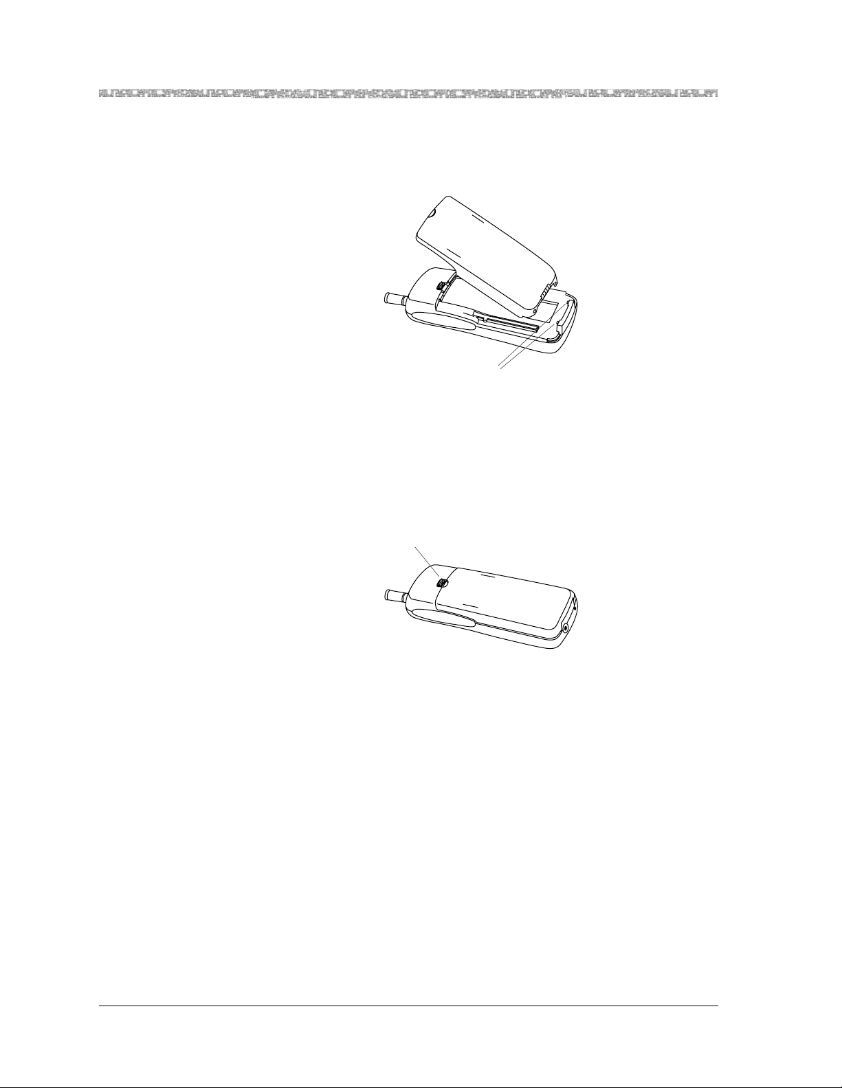
To insert the battery pack into the handset:
1
Insert the two small re ctangular tabs locat ed a long the bottom back edge of the
handset into the two rectangular holes along the bottom front edge of the battery
pack.
Rectangular tabs
Figure 5. Inserting the Battery Pack into the Handset
2
Press the battery pack downward until it clicks into place.
The battery pack must be charged prior to using the handset. See “B attery
Charger” later in this chapt er for instructions.
3
To remove the battery pack, slide the spr ing latch upward (awa y from the battery
pack). Then, grasp both sides of the battery pack and gently pull the battery pack
upward and out.
Spring latch
Figure 6. The Location of the Spring-Latch on the Handset
Performing the Registration
The Registration
Security Feature
14
Issue 1, May 2000
If one of the following registration restrictions occurs, registration between the
handset and the DRM cannot proceed.
•
•
•
•
•
MDW 9040 Wireless Pocket Phone Installation, Troubleshooti ng, and Use,
The base is not in the registration mode.
The handset and the bas e have an established RF link.
The associated switch port is off-hook.
The associated switch is sending the handset messages.
The DRM is already registered to another handset which is in range.
503-801-190
Page 26

Setting Up and Registering the Handset Installing and Registering the MDW 9040 Pocket
Registering a Handset
and a DRM
To register your tel ephone with each DRM to which it will be connected:
IMPORTANT NOTES: Between Step 2 (entering Registration Mode on
the handset) and Step 3 (pressing the Registration button on the DRM)
in the procedure described on the next page, there is a 5-minute time
limit. If no further action is taken during this span of time, the DRM
will time out, and you mus t star t th e r egistration proces s again.
The DRM will NOT allow the registration process if there is anything
preventing r eg istration such as the DRM is actively communicating
a previously registered handset. For more information about these
restrictions, see “The Registration Security Feature” on the
previous page.
1
Signal the DRM that registration is about to start by pressing the Registration
button on the DRM corr espon ding to the line ( 1 or 2) to which the handset will be
registered.
IMPORTANT NOTE: At power-up, a new handset (never been registered
befo re), imm ediately shows th e Regist r a t ion scre e n:
REGISTRATION
Zone 1
Zone 2
Reg
UnReg
Then, do one of the foll owing:
* If this IS a registration for a new handset and the above display screen
appears on your hands et display, proceed to Step 5.
* If this display screen does not appear or if this registration procedure
is NOT for a new handset, you must use the Menu b utton to enter
Menu Mode. Begin wit h St ep 2 below.
2
At the handset, press
Menu
.
The initial Menu screen is displayed.
3
Press to move the arrow to the ri ght o f the sele cted op ti on to Conf iguration
and then press the softkey below Sel.
The initial Configurat ion Menu screen ( Option) is di splayed.
4
Press
move the arrow to Registration and then press the softkey below
to
Sel.
The Regis tration screen (Zone 1 and Zone 2) is displayed. The curr ent zone
setting, if any, is flashing.
MDW Wir eless Pocket Phone Install ation, Troubleshooting, and Use,
503-801-190 Issue 1, May 2000
15
Page 27

2
Installing and Registering the MDW 9040 Pocket Phone Mapping the MDW 9040 to the
5
Do one of the following:
~
For single-zone operation, move the arrow to whichever zone
(Zone 1 or Zone 2) the handset will be used and then press the soft key below
Reg. The following occurs:
•
The selected DRM makes checks regarding the handset registration
request.
•
If there are no unexpecte d conditions, the assoc iated base module and
handset communicate using special link-up signaling
•
The handset displays a “Reg istration Complete” message t o the user.
~
For dual-zone operation, move the arrow to whichever zone
(Zone 1or Zone 2) it will be used with this DRM and then press the softkey
below Reg.
In the future, you will need to re gister the handset with the other DRM with
which it will be associated.
•
The second DRM makes che cks regarding the h andset registratio n request.
•
If there are no unexpecte d conditions, the assoc iated base module and
handset communicate using special link-up signaling
•
The handset displays a “Reg istration Completed” message to the user.
The LEDs on the DRM have the f ollowing meaning:
Flashing
Flashing
6
T o e xit an y screen a nd mov e back to the pre vi ous screen OR if you do not want to
Power
LED Handset is in Registration Mode for
Line 1
Control
LED Handset is in Registration Mode for
Line 2
make any changes at this time, press the softk ey below Exit.
7
Proceed to the inst ructions in the section titled “Mappin g the MDW 9040 to the
Correct Communications System.”
Removing Registration
Between a Handset and
a DRM
To eliminate a registration between handset and DRM:
1
Follow Steps 1 through 6 of the registration procedure above.
2
At the Registration screen (Zo ne 1 and Zone 2), press the softkey below UnReg.
Mapping the MDW 9040 to the Correct Communications System
The communicati ons sys tem you use determin es what informati on the MD W 9040 Pocke t Phon e can di splay and
how the phone lines and programmable/intercom/drop buttons are identif ied. (For a detail ed description of
Button Mapping,” see the appropriate “Button Mapping” topics in the “MDW 9040 Compatibility” section in
Chapter 5.)
Reacti n g to the Button
Mapping Display
Screens
16
Issue 1, May 2000
During the registration process between the handset and the DRM, the handset notes
the type of DRM to which it is connected ( either a DRM-D or a DRM-E). When your
handset has been successfully registe r ed, a mes sa ge appears on the screen infor mi ng
MDW 9040 Wireless Pocket Phone Installation, Troubleshooti ng, and Use,
503-801-190
Page 28

Mapping the MDW 9040 to the Correct Communications System Installing and Registering the
you to which communications system your handset has been mapped. The table
below lists the default swit ch interfaces fo r each DRM type.
If your handset has been
registered to this type of DRM:
and the Switch
Protocol Is:
The Default Switch
Interface Is:
DRM-D DCP DEFINITY
DRM-D TDL MERLIN MAGIX
DRM-E ATL MERLIN (other)
NOTE: If the Switch Interface should be MERLIN (410/820), see procedures on the
next page.
DRM-E ETR PARTNER
NOTE: If the Switch Interface should be MERLIN (other), see procedures on the nex t
page.
As indicated in the table above, use the procedures on the next page if the switch
interface for your handset is not correct.
1
2
Menu
Pres s to ente r Menu Mode.
Press the Select-Row ( ) button until the arrow is to the right of
Configuration and then press the softkey below Sel.
3
At the initial Configure Mode screen, press the softkey below More.
4
Press until the arrow is to the right of Button Map and th en pr e s s th e
softkey below Sel.
5
From the Button Map screen s, choose Partner, or Def inity, or Merlin (410/820),
or Merlin (other). When the arrow is to th e right of the correc t switch interface,
press the softkey below Sel.
Filling Out the Handset Label
Once you have checked to make sure that the MDW 9040 is mapped to the corr ec t com mu nications system, f ill
out the handset label on the back of the handset.
Note:
The MDW 9040 has a label on the back of the handset near the top where you can record:
•
•
The MDW 9040 display shows the status of up to 12 lines or
programmable/intercom/drop buttons. Since the MDW 9040 is
compatible with several different communi cations systems, dia grams of
the button m appings for these systems are pro vided in Chapter 5.
Your extension number.
The mapping of your MDW 9040 line button s t o those on a wired phone for your
communications sys t em.
MDW Wir eless Pocket Phone Install ation, Troubleshooting, and Use,
503-801-190 Issue 1, May 2000
17
Page 29

2
EXT.
A
Installing and Registering the MDW 9040 Pocket Phone Other Han dset Configura tion
IMPORTANT NOTE: Before filling out the handset label, read
these notes.
* Use a pencil or ballpoint pen on the label, in case you want to
erase th e informat ion later.
* DO NOT use felt-tip or other types of non-erasable markers.
* Also, DO NOT remove the label. Leave it on the back of
the handset.
B
C
D
1
2
3
4
5
6
7
EXT.
A
B
C
D
1
2
3
4
5
6
7
8
8
Figure 7. The Handset Label
To fill out the hand se t label:
1
Write your e x tension number on the labe l.
2
Locate the section in Chapter 5 that describes the button mapping for your
communications system; then copy th e mapping to the label for ease of reference.
Other Handset Configuration Options
Before using your hands et and its display, you may also wish to do the following :
•
Choose the Language in which the display message will appear . For more
information about choosing the language for all messages, see Chapter 3.
•
Select the Disp lay Message Length (1 or 2 lines). For more information about
selecting mess age length, see Chapt er 3.
18
Issue 1, May 2000
MDW 9040 Wireless Pocket Phone Installation, Troubleshooti ng, and Use,
503-801-190
Page 30

Installing and Using the Battery Charger Installing and Registering the MDW 9040 Pocket
Installing and Using the Battery Charger
The battery quick charger charges battery packs in both the spare battery compartment and in the handset when
the han d set is placed into the h an dset cradle. If both are prese n t at the same time, char g ing in the spare battery
compartment is suspended until the battery pack in the handset is fully charged.
Note:
Do not touch, push, or pull any exposed battery contacts.
“Battery Charge State Label”
WT Cradle
Spare Battery
Compartment
Battery Contacts
Spare Battery
Compartment
Figure 8. The Battery Charger
Battery Charger Feat ur es
The battery charger of fers thes e features:
•
The Spare battery compartmen t refreshes the battery pac k automatically by
fully disc harging it before recharging it. This process reduces or eliminates the
potential “memory” effect. Memory effect, which reduces a battery’s capacity,
occurs over time when you repeatedly recharge a batte r y before it is fully
discharged.
•
The handset cradle charges a battery pack in the handset.
•
The REFRESH button, when pressed, refreshes the handset battery pack in the
handset cradle by fully discharging the battery pack before recharging it.
•
The REFRESH and the HANDSET LEDs go on when the REFRESH button is
pressed and stay lit until the battery pa ck finishes discharging.
REFRESH
REFRESH
Handset Cradle Battery Contacts
HANDSET
SPARE
Button
LED
LED
LED
•
The HANDSET LED, when lit, indicates that the handset battery pack is
installed in the handset, and the handset is in the handset cradle.
•
The SPARE LED, when lit, indicates that a batt er y pack is in the Spare battery
compartment.
Note:
Before you use the MDW 9040 Pocket Phone handset for the first time,
the battery pack mu st be charged.
MDW Wir eless Pocket Phone Install ation, Troubleshooting, and Use,
503-801-190 Issue 1, May 2000
19
Page 31

2
Installing and Registering the MDW 9040 Pocket Phone Installing and Using the Battery
The color of the battery charger's LEDs indicates the state of the corresponding battery pack, as shown in the
following table:
Battery Charger
LED State
for the SPARE
Battery Status LED
for the HANDSET
Battery Status LED
Steady orange Battery is charging Battery is charging N/A
Steady green Ba ttery is fully cha rged Batte r y is fully charg e d N/A
Flashing red
See Note below.
Stea dy re d Bat te ry is in th e
Note:
If either the SPARE LED or the HANDSET LED is flashing red, both ba ttery packs must be
Battery has o ne of the
following prob lems:
Is not seated properly in
the charger
Has dirty contacts
Is defective
Discharge portion of the
Refresh cy cl e.
Battery has one of the
following problems :
Is not seated properly in
the char g er
Has dirty contacts
Is defective
Battery is in the
Discharge portion of the
Refresh cycle.
removed fro m the char ger to cle ar the flashing -red condit ion. Addre ss the pos sible probl ems for
one battery pack at a time to determine whether one is ba d.
Positioning the Battery Charger
Before you install the battery charger, note the following considerations:
for the REFRESH
Status LED
N/A
Battery is in the Discharge
portion of the Refresh cycle.
Note:
The battery charger can be placed on a desk, or it can be mo unted on a
wall.
•
Locate the battery charger within 5 feet (1.6 m) of a properly wired ele ctrical
outlet that is n ot c o n tr o ll ed by an On/O ff sw itch.
•
If your communications system uses an uninterruptible power supply, such as a
backup generator, you may want to connec t the battery charger to that power
supply.
•
Do not locate the battery charger where it will be exposed to direct sunlight or
water.
!
WARNING:
The rechargeable battery pack may contain elements that are harmful to
the environment (for example, nickel). Do not burn or puncture the
battery. As with other batteries of this type, burning or puncturing could
release toxic material that could cause injury. Do not dispose of it in
household garbage. For information about recycling or proper disposal,
consult your local solid waste (garbage) collection or disposal
organization.
20
Issue 1, May 2000
MDW 9040 Wireless Pocket Phone Installation, Troubleshooti ng, and Use,
503-801-190
Page 32

Installing and Using the Battery Charger Installing and Registering the MDW 9040 Pocket
Installing the Battery Charger
•
If you are wall-mounting the battery charger, follow Steps 1 through 7.
•
If you are desk-mounting the battery charger, follow only Steps 1, 5, and 7.
To install the battery charger:
1
Check to make sure the battery charger’s power cord is unplugged from the wall
outlet before continuing. If you are desk-mounting, skip to Step 5.
2
To wall-mount, place the battery char ger’s wall-mounting templ ate (located on
the last page of this book) against the wall. Choose a location bac k ed by a
wooden stud (if una vailable, use toggle bolts instead of the s upplied wood
screws). Hold the template straight; us e a leve l if needed.
3
Mark the locations for the two wall-mounting screws, and then remove the
template fr o m the wall. Lightly tap a nail into the wall to star t the holes.
4
Place the screw through the wa ll spacers so that the screw head nests in the
indentation on the spa ce r. Start the screws, and scre w them in until the wall
spacers rest against the wall.
5
Insert the battery charger’s power cord/AC adapter into the battery charger. If yo u
are desk-mounting the battery charger, skip to Step 7.
6
Place the keyhole-shaped openings in the back of the batte r y charger ov er the
scre w heads and wall spacers, then slide the ba ttery charger do w n ward into th e
groove in th e wall spac er s to lo ck it into pl ace.
7
Plug the battery charger’s power cord/AC adapter into a properly grounded,
3-pr o ng wall outlet that is n ot c o nt r o lled by an On /O ff sw it ch.
Inserting the Handset into the Battery Charger’s Handset Cradle
Positioning and
Inserting the Handset
Correct pos itioning of the handset in the charger is impor tant to ensure proper
charging:
1
Position the handset (with either battery pack attached) so that the two small
round holes in the bottom of the handset fit over the two guide pins on the bottom
of the handset cradle.
2
Rock the handset back into t h e cradle until it is f ir mly seated with the back of t he
handset battery pack against the bac k of the handset cradle.
When the handset has been inserted correctly, the following occur:
•
The HANDSET Battery Status LED lights.
•
If the handset i s pla ced off-hook, the OFF-HOOK icon in t he dis play i s no l onge r
visible.
•
Any call tha t was in progress is terminated.
•
After 15 seconds, the handset enters the energy-saving “sleep” mode.
MDW Wir eless Pocket Phone Install ation, Troubleshooting, and Use,
503-801-190 Issue 1, May 2000
21
Page 33

2
Installing and Registering the MDW 9040 Pocket Phone Installing and Using the Battery
HANDSET LED
Guide Pins
Figure 9. Inserting the Handset into the Batt ery Ch arger
Removing the Handset
from the Handset
Cradle
To remove the handset fr om the handset cradle, lift it out.
Extending Battery Life
The battery ch arger will charge a battery pack in the handset if you simply insert the handset in the battery
charger's handset cradle; however, the Refresh process fully discharges the battery pack before recharging it,
thereby ensuring the best possible c harge and the longest ta lk time. For more information about the batter y
charger, see the nex t se ct io n , Positioning and Installing the Battery Charger.
“Memory effect” reduces a battery's capacity and can occur when you repeatedly recharge a battery pack before
it is fully discharged. The nickel metal hydride battery pack shipped with your MDW 9040 is resistant to the
memory effect. Even so, it is recommended that you refr es h your battery pack at least once a week.
The follo wing table shows how long refreshing takes, depending on how much cha rge is left in the battery pack
when you insert it into the charger and press the REFRESH button:
Battery Pack
Standard Battery
Pack
Battery-Pack Charge State Average
Discharge
Time
Low charge ( Battery icon is lit) 0.5 hours 1.25 hour 1.75 hours
Full charge 3 hours 1.25 hour 4.25 hours
Average
Recharge
Time
Average
Total Time
Extend ed Battery
Pack
22
Issue 1, May 2000
Low charge ( Battery icon is lit) 0.5 hours 3.25 hours 3.75 hours
Full charge 8 hours 3.75 hours 11.75 hours
MDW 9040 Wireless Pocket Phone Installation, Troubleshooti ng, and Use,
503-801-190
Page 34

Installing and Using the Battery Charger Installing and Registering the MDW 9040 Pocket
Note that your handset will consume power both during talk time (when the hands et is turned on) and during
standby ti me (when the handset is turned off, but out of the battery charger). The following chart illustrates
typical power usage:
Battery Use at Full Charge
Type
Approximate
Talk Time
Approximate
Standby Time
Standard Batte ry Pack 3 hours 22 hours
Extended Battery Pack 8 hours 72 hours
As a guideline, you can expect a 1-hour reduction in talk time for every 7 hours of standby time. Similarly, you
can expect a 7-hour reduction in standby time for every hour of talk time.
The follo wing s teps will ensure an uninterrupted supply of power to your MDW 9040 Pocket Phone:
•
If you have only one battery pack, be sure to refresh it at least once a mont h. You
can refresh it by:
~
Placing it in the Spare battery compartment of the battery charger.
~
Leaving it in the handset, placing the handset in the hands et cradle of the
battery char ger, and pressi ng the REFRESH button.
•
If you have two bat tery packs, exchange the packs between the handset and the
Spare battery comp ar tment at least once a week, so that each battery pack is
automatically refres h ed. (Alternate the battery pa cks even if the handset battery
never flashes the Ba tter y icon in the hands et display to indic ate a low battery
condition.)
•
The average battery life for both the standard and the extended battery packs is
approximatel y one year, assuming that the battery is discharged and charged once
a day. If the ba ttery packs are discharged an d charged twice a day, the life
expectancy is approximately six months.
Note:
Depending on the level of memory effect that the batter y pack has, it is
sometimes necess ary to refresh the battery pack two or more times:
~
Insert the battery pack in the Spare battery compartment of the battery charger
and leave it there until the SPARE LED is steady green. Remove the battery
pack from the charger, then reinsert it, and leave it until the SPARE LED is
steady green a second time.
~
OR, with the battery pack in the handset, insert the handset in the handset
cradle, press RE FRESH, and leave it there until the HANDSET LED is steady
green. Remove the handset from the handset cradle, then reinsert it, press
REFRESH again, and leave it until the HANDSET LED is steady green a
second time.
MDW Wir eless Pocket Phone Install ation, Troubleshooting, and Use,
503-801-190 Issue 1, May 2000
23
Page 35

2
Installing and Registering the MDW 9040 Pocket Phone Inserting a Battery Pack into the
Inserting a Battery Pack into the Spare Battery Compartment
Inserting the Battery
Pack
Spare Battery Pack
Slide the battery pack (or an optional extended battery pack) into the spare battery
compartment until it is firmly seated, that is, with the back of the battery pack against
the back of the Spare battery compartment. Do not force the battery pack down.
The Spare battery co mpartment has a vertical ridge o n each side that serves as a
“guide rail” for pos itioning the standard battery pack.
Vertical Guide Rail
Spare Battery
Pack Guide Pi n
Battery Charger
Contacts
Spare Battery
Compartment
Handset Cradle
Removing a Battery
Pack fro m the Spare
Battery Compartment
24
Issue 1, May 2000
Vertical Guide Rail
Figure 10.
Inserting Battery Pack Into Spare Battery Compartment
SPARE
LED
To remove a battery pack from the Spar e battery co mpartment of the charger, lift the
battery pack up and out.
MDW 9040 Wireless Pocket Phone Installation, Troubleshooti ng, and Use,
503-801-190
Page 36

3 Using the MDW 9040 Pocket Phone
Important Safety Instructions
Please see “Important Safety Instructions” pro vided at the beginning of this manual.
About the Handset
The MDW 9040 Po cket Phone supports normal operation of all of the features of the switch as far as is practica l
within the limitations of its reduced size and power and the nature of wireless operation. There are very few
diffe r ences in operation between the wireless MDW 9040 Pocket Phone and a wired deskset.
This chapter describes the handset and how to use it. It also explains how to use a headset.
MDW 9040 Wireless Pocket Phone Installation, Troubleshooting, and Use,
503-801-190 Issue 1,May 2000
25
Page 37

3
Using the MDW 9040 Pocket Phone About the Handset
Handset Features
17
16
15
14
13
12
11
10
1
Antenna
— Extend fully or retract fully to use
hand set. Ex tend fully to maximize th e ha n dset ra ng e
1
and vo ice quality.
2
Receiver
— Receives the sound of your caller’s
voice, unless a headset is connected.
3
2
Handset Display with Backlighting
— Displays
status of lines and range as well as system and local
programming messages. F or a detailed descript ion,
see “Handset Display” on the next page.
4
3
Four Softkeys/Column buttons
with Select button to choose a line or
— Use together
programmable/inte rcom/drop button.
5
Menu button
4
Redial
Menu
Menu
Feat/P
9
123
Conf
456
Trans
789
Hold
ABC DEF
JKL MNOGHI
TUV WXYZPQRS
0
OPER
5
6
7
6
Select-Row button
pointer, and, together with the Column buttons, to
choose a line or progra mmable/intercom/drop button.
Also used to “wake -up” the phone.
7
Dial pad
calls or accessing features .
8
Headset Connector
to use the head set.
9
— Press to p u t a call on hold.
Hold
— Press to enter Menu Mode.
— Use to mov e th e Se le ct- Ro w
— The usual 12-button dial pad for placi ng
— Plug in the headset adapter
9040
10
8
11
— Press to tr ansfer a ca ll to another extension.
Trans
— Press to conference in (add) another person
Conf
to your call.
Figure 11. The MDW 9040 Wireless Phone
12
Feat/P (Feature/Program)
— Press t o access
switch-dependent features or to enter Programming
Mode.
13
(On/Off)
— Press to turn the handset on. ON appears in handset display. To turn off, press again.
Turn on to place or answer a call, and turn off to “hang up.”
14
Redial button
15
Volume control
16
Mute button
17
Lanyar d Lo op
— Press to redial the last number manually dialed from the handset.
— Press “+” to increase or “
-
” to decrease the volume of the receiver or alerter.
— Press to turn the handset microphone off for privacy.
— Attach an (optional) lanyard for carryin g the handset.
The Handset Display
The MDW 9040 Pocket Phone display has one line of icons and four alphanumeric-character lines (up to
16 digits and/or characters on each line) to provide you with status information and programming options. The
26
Issue 1, May 2000
MDW 9040 Wireless Pocket Phone Installation, Troubleshooti ng, and Use,
503-801-190
Page 38

About the Handset Using the MDW 9040 Pocket Phone
MDW 9040 displ ay also pr ovide s Back lig hting so th at you can read your displ ay in poor ly-lit environments. You
can choose to turn on the Backlighting feature or turn it off as well as select the amount of time the feature is on.
The following default screen appe ars initially on the hand set display.
Monday, July 19, 1999
3
5
1
A
6
2
B
Figure 12. The MDW 9040 Display
•
The top row of the display shows status ic ons. The following lis t describes the
7
3
C
meaning of each icon (from left to right).
1 2 3 4 5 2 7 8 96
Figure 13. The Top Row of the Display Showing the Handset Icons
Message
1
The
Radio Frequency (RF) Signal Level
2
The
signal strength.
icon ( ) lights when you have a message.
icon ( ) is divided into four bar s to sh o w the r adio frequenc y
8
4
D
Handset Off-Hook Status
3
The
Battery Charge Level
4
The
more information, see “ Low Battery Indicator” later in this chapter.
Vibrator Status
5
The
Ringer Status
6
The
no icon is displayed.
Speaker Mute Status
7
The
pressing the Mute button on the side of the handset.
More Options Available
8
The
icon ( ) lights when the vibrator has been activated.
No Ring
or
•
The second and third rows of the display shows the inform ation you would se e
icon ( )lights when the handset or the headset is off-hook.
icon ( ) is divided into four sections to show the remaining battery life. For
icon ( ) lights when the alerter is disabled. If the ale rter is enabled ,
icon ( ) lights when the handset or headset microphone has been turned off by
icon ( ) lights when there are more options that are available.
on the top line of a wired system phone’s dis play. The information varies
according to which communications system you are using. For example, the
MDW 9040 Wireless Pocket Phone Installation, Troubleshooting, and Use,
503-801-190 Issue 1,May 2000
27
Page 39

3
Using the MDW 9040 Pocket Phone About the Handset
display may sho w the current date, the numb er you are calling, or caller ID
information (if the system supports this feature). Th is display line i s also used for
feedback when testing and programming the handset.
Line Status Indicators
Note:
When the MDW 9040 is shipped from the factory, it is set f or a 2-line
display. (See the default display screen on the previous page.) However,
the display message length can be changed to 1-line if so desired. If you
choose 1-line of information for your display, four additional
programmable b uttons appear on the third line of the display.
•
The fourth and fifth rows on the display show the line or
programmable/inte rcom/d rop b uttons . Li ne Statu s indic ators , such as a tria ngle or
a square next to t he line you are us ing or to whic h you wi ll be con necte d once you
turn on the phone are disc ussed in Line Status Indicators in the next sect ion. F or
more information abou t button-mapping, see Chapter 6.
Note:
When the disp lay is blank, the handset is either tur ned off or in the
power - saving “sleep” mode. You can activate th e dis play and
Backlighting (if programmed) by press ing to “wake up” the
handset and go off-hook, or by press ing
Menu
,
, or the volume
buttons (labeled “+” and “-” on the side of the handset) to “wake it up.”
There ar e up to 12 st atus indicators (1 through 8, A through D). See Figure 2. Each
one corresponds to a specific outside line or programmable/intercom/drop button.
(The function of thes e s tatus indicators v aries, depending on the communications
system you are using — see the Button Mapping topic for the appropriate
communications system switch in Chapter 6, “MDW 9040 Pocket Phone
Comp at ib i li ty.”) Th e sta tu s in d i cators show ei th e r a tr i an g le ( ) or a rectangle ( ),
signify ing the following activity:
Note:
All line status indicators time out after approximately 10 seconds if the
handset is on-hook. When time-out occurs, the handset goes into the
energy-savi n g “s le ep m o d e. ”
For PARTNER Systems:
A triangle ( ) showing line sta tus is the equiv alent of a green LED o n a wired sys tem
phone.
A rectangle ( ) showing line status is the equivalent of a red LED on a wi red system
phone.
For all other Systems:
A rectangle ( ) showing line st atus is the equivalent of a green LED on a wire d
system phone.
A triangle ( ) showing line status the equivalent of a red LED on a wired system
phone.
28
Issue 1, May 2000
MDW 9040 Wireless Pocket Phone Installation, Troubleshooti ng, and Use,
503-801-190
Page 40

About the Handset Using the MDW 9040 Pocket Phone
3
The Select-Row Butt on
and the Column
Buttons
The MDW 9040 Pocket Phone can display the status of up to 12
lines/in tercom/programmable buttons, but the number of lines supported by
compatibl e communications system switches varies.
Use the Select-Row ( ) button to move the pointer (arrow on the right side of
the display) up one row. The pointer moves to that row, cycling through the three
rows in turn, and then returning to the bottom row.
Located under the display are four Column buttons, labeled
(in Menu
Mode, these four buttons are calle d Softkeys). Eac h Column button affects one of the
four columns or programma ble/intercom/drop buttons directly above it
Thus, once you have moved the Select-Row ( ) button, press the Column
button ( ) to select the line or programmable/intercom/drop button in that row.
For example, if you pr es s the s ec ond Column button from the left (s haded in
Figure 19 below), you sele ct Line 2, a s indicat ed by the t ria ngle (for PART NER) next
to 2 in the figure below.
Selection rectangle
Selection triangle
5
1
A
6
2
B
7
3
C
8
4
D
Placing the Handset
Off-Hook
shade this but ton
Figure 14. Using the Row and Column Buttons Together
To place the handset off-hook:
1
Press
.
This action wakes up t he handset and tells the switch that the handset is off-hook.
The icon on the display scre en lights.
The Home screen appears on the display. See Figure 17 for a sample display.
Note:
If you press a second time, the handset goes off.
For more information about using the display to se t or cha nge the handset settings ,
see “Changing the Handset Settings” later in this section.
MDW 9040 Wireless Pocket Phone Installation, Troubleshooting, and Use,
503-801-190 Issue 1,May 2000
29
Page 41

3
Using the MDW 9040 Pocket Phone About the Handset
Signal Strength and
Range Indicators
Signal Strength is indicated by the number of bars in the Radio Frequency (RF)
Signal Level icon ( ). Four bars indicate optimal signal leve l, while one bar or no
bars indicate poor signal level.
Note:
The antenna must be either fully retracted (for short range) or fully
extended (for maximum range) to use the Pocket Phone.
The handset provides an audible and a visual signal to alert you when the handset is
near the end of the range of the radio mod ule. Depending on how far away the
handset is fr om th e radio module, the signals function as follows:
•
OUT-OF-RANGE During a Call: The handset emits 2 beeps and/or turns on
the vibrator f or a short period of time and flashes the icon continuously.
Whic h means: Out of range. You have walked into an area that is near the end of
the operating range of the radio module. You can continue your conversation or
initiate a call, but you are likely to experience a degradation in voice quality or
possible loss of communications link. If a loss of link occurs , the call will be
automatically placed on hold, before the handset will turn off. To talk with your
party, move back to ward the radio module, press , then proceed as you
would for any call placed on Hold.
•
OUT-OF-RANGE During a Call Attempt: When you try to make a call, the
handset emits 2 beeps and flashes the icon twice; then the handset
automatically turns off.
Whic h me ans: Cannot es tablish communication link. You are complete ly out of
range of the radio module. To make the call, move back towards the radio mod ule
and try again.
Refer to Chapter 5, “Troubleshooting,” for additional information about
out-of-range conditions.
Low Battery Indicator
The Battery Charge Level is indicated by the number of cells displayed on the
Battery C harge Level icon ( ). If all four cells are filled in, the battery is fully
charged. If two or less ce lls are displayed, it is time to recharge the battery.
The standard battery pack has approximately three hours of continuous talk time
after being fully charged.
The optional extended battery pack has appro ximately eight hours of continuous
talk time after being fully charged.
When the handset is On and the battery power is low, the handset will emit two beeps
and/or turns on the vi brator for a short period of time and the icon on the
handset display will flash. When this occurs, you have five minutes or less of talk
time left. At this point, you can either:
•
Complete your call, turn the handset of f, and recharge the batt ery pack, OR
•
If you have a charged spare battery pack, place your call on Hold and replace the
handset battery pa ck with the spare battery pack. Wait 6 to 10 seconds, then turn
the handset on and proceed as you would for any call place d on Hold.
Note:
When the battery power is low, the two beeps will sound each time you
press until either the batter y is drained or you replace the battery. If
you continue talking, the handset will turn off when the battery pack is
drained. Your call will be placed on Hold automatically so tha t you ca n
swap battery packs or pick up the call on another telephone.
30
Issue 1, May 2000
MDW 9040 Wireless Pocket Phone Installation, Troubleshooti ng, and Use,
503-801-190
Page 42

Setting or Changing the Handset Settings Using the MDW 9040 Pocket Phone
3
Adjusting the V olume of
the Handset
The volume control is located on the side of the handse t. This control raises (the “+”
button) and lowers the volume (the “
-
” butto n) of th e A lerter and the Receiver . There
are four incremental volume levels. If the Ringer is enabled on the user menu, the
display indicates the current volume level with arrows (>>).
•
To raise or lower the Alerter (or Ringer) volume: While the MDW 9040 is
awake but on-hook, press the “+” or the “-” button. Each time you press the “+”
or “
-” button, the handset makes a “chirping” sound, and the display shows the
current volume level:
Ringer:>>>
5
1
A
•
To raise or lower the volume of the Handset Receiver (or the Earpiece): While
6
2
B
7
3
C
8
4
D
the MDW 9040 is of f-hook, press the press the “+” or the “-” button. Each time
you press the “+” or “
-” button, the handset audio dial tone level changes, and
the display shows the current volume level:
Ear Le ve l: >> >
5
1
A
6
2
B
7
3
C
8
4
D
Muting the Handset or
Headset Microphone
To turn off th e mic ropho ne ass ociat ed with the handset or h eadset whil e the handset is
off-hook:
Press the Mute ( ) button on the side of the handset.
The microphone is turned of f. The
Note:
If you press a second time, the Mute function is turned off.
icon lights.
The Mute function is also turned off wh en the handset goe s on-hook or if
the user changes to an other line.
Setting or Changing the Handset Settings
You can set or change the handset settings by entering Menu Mode (pre s s
for the followi ng functions:
•
From the CONFIGURE menu
~
Register your handset with the appropriate DRM
~
Select the Language in which the dis play message will appea r
~
Choose the Length of the display Message (1 or 2 lines)
MDW 9040 Wireless Pocket Phone Installation, Troubleshooting, and Use,
503-801-190 Issue 1,May 2000
Menu
and completing the procedures
)
31
Page 43

3
Using the MDW 9040 Pocket Phone Setting or Changing the Handset Settings
•
From the OP T IONS menu
~
Choose the Type of Alerter you want to hear on your phone, either the ringer
or the vibrator
~
Tur n on Backlighting for your telephone display
~
Tur n on the Line Pre-Se le ct feature
~
Hear Key Cli c ks as you press keys on the telephone dial pad
•
From the TEST MODE menu
•
Enter Local Test Mode, which enables you to te st the alerter, vibrator, and
display
•
Enter Wireless Test Mode, which enables you to test sound clarity, signal
strength, and voice quality
Selec tin g a Me nu Item
The Selection control buttons are used to identify fields within three rows (the 3rd,
4th, and 5th rows) on your display.
•
After p ressing to enter Menu Mode, use the Se le ct-Row ( ) button to
Menu
move the arrow, which is pla ced to the right of the line currently being viewe d, to
the appropriate option. The cursor moves down from the second to the third row,
then to the fourth row, and then cycles back to the second row again.
This action w akes up the handset and enables all of the other hand se t buttons.
•
The four Softke ys ( ) beneath the display al low you to select the item s sho wn
on the fifth row of the display screen.
For example, to select an option on the handset display:
Press
Menu
to enter Menu Mode.
1
The display shows the initial Menu screen.
Options
Configuration
Test Mode
Sel
Exit
32
Issue 1, May 2000
Note:
2
The currently active op t i on, if there is one, is flashi ng.
Press th e Se le ct-Row ( ) button unti l the ar r ow is pl ac ed to the righ t of th e
row on which the selected option is located. For example, press until the
arrow is placed to the right o f Options as in the example above.
3
Press the Softkey ( ) below Sel (for Select).
MDW 9040 Wireless Pocket Phone Installation, Troubleshooti ng, and Use,
503-801-190
Page 44

Setting or Changing the Handset Settings Using the MDW 9040 Pocket Phone
3
Responding to the Last
Line on the Screen
On the bottom row of the screen, you ma y see SEL, MORE, or EXIT such as in the
following exam ple:
OPTIONS MENU
Ringer
Note:
Vibrator
Sel
The currently active option, if there is one, is flashing.
More
Exit
These options indicate:
•
SEL(ECT) — you can SELECT the currently high lighted option such as Sys tem
or Language by pressing the softkey below SEL.
•
MORE — there are more opti o n s than shown on the current screen. To see the
next screen of options, press the softkey below MORE.
•
EXIT — available on many screens, this option allows you to exit the current
screen and go up one level to a previous screen.
Using the Configuration a n d Option Menus
As you read the following information, follow “A Flowchart for the Configuration, Options, and Test Mode
Display Screens” provided on page 35.
Configuration Menu
Before you begin to use your MDW 9040 Pocket Phone, you must configur e the
telephone for th es e options accessed through Configuration Menu:
Enter the Configuration Menu in the following manner: Press to enter
Menu
Menu Mode, press the Select-Row ( )button to move the arrow to
Configuration, and then press the soft key below Sel.)
•
REGISTERING the handset with the correct DRM(s)
Note:
For detailed ins tructions on registering the handset with the appropriate
DRM(s), see the information included in Chapter 2 o n page 13.
•
Selecting the LANGUAGE in which the display menu text wil l ap p ear
You can choose one of four languages in which the display messages will appear
on your telephone. The se languages include: English or French
or Latin American Spanish or Brazilian Portuguese.
•
Choosing the LENGTH of a display MESSAGE
When the MDW 9040 is shipped from the factory, it is set for 2 lines of text, on
the second and the third l ine s of the displ ay scr een. Ho we v er , the dis play mes sage
length can be changed to 1 line of text if so desired.
MDW 9040 Wireless Pocket Phone Installation, Troubleshooting, and Use,
503-801-190 Issue 1,May 2000
33
Page 45

3
Using the MDW 9040 Pocket Phone Setting or Changing the Handset Settings
Options Menu
Once your handse t is registe red with the correct DR M, you ca n cus tomize your MDW
9040 with these options accessed th rough the Options Menu:
Enter the Options Menu in the following manner: P r es s to enter Menu
Menu
Mode, press the Select-Row ( )button to move the arrow to Options, and then
press the softk ey be low Sel.)
•
Choosing the Type of ALERTER you want to hear on your phone
Select either the Ringer or the Vibrator option to alert you when there is an
inco ming call .
~
The Ringer is an audible signal to notify you of an incoming call. If a call
comes in while the phone i s idle , the hands et rings . If you are alrea dy on a call ,
the handset chirps softly. You can adjust the volume of the alerter by pressing
the “+” button or the “-” button on the si de of the handset when the phone is
turned off.
~
The Vib ra tor can be used in pla ce of the alert er i n situ ations whe re you do not
want to disturb others with an audible ring.
Note:
The No Ring icon ( ) is lit on the handset when the ringer is turned off.
When th e Vibrat or f ea tu r e is ac tive, the ( ) is lit.
Both the rin ger and the vib rator ca n be dis abled a t the s ame time. In this case
the only notification you have of an incoming call is that a line sta tus
indicator (a tri an gle or a squ are, d ependi ng on your c ommunica tions system)
flashes in the display.
•
Activating the BACKLIGHTING Feature for your telephone display and if
turned on, choosing the amount of time the Backlighting is active.
Backlighting for the handset display allows you to see the display in poorly-lit
environments. The display is fact ory set to ON for the MDW 9040 Pocket Phone.
However, the Backlighting Feature can also be turn OFF.
If you choose to turn ON the Backlight ing feature for your handset displ ay, you
can also choose the amount of time the Backlighting is acti ve. The options are
7 seconds, 15 seconds, and 30 seconds.
•
Turning on the LINE PRE-SELECT Feature
Line Preselection lets you choose the line or button you want to use before
turning t he handset on. For exampl e, suppose your phone is ringing, but y ou want
to pick up a call that is holding on another line inste ad of the ringing call. In
normal operation, the communications system automatically connects you to the
ringing line as soon as you turn on the handset. With Line Preselection enabled,
you can select the line you want to connect to before turning on the handset.
The Line P r e-S e lect Featu r e ca n be tu rn ed ON or turned OFF.
•
Choosing to Hear KEY CLICKS as you press keys on the telephone dial pad
You can choos e whet her you want to hear key clicks as you enter numbers into
the handset. The Key Clicks Feature can be turned ON or turned OFF.
If you choose to turn ON the Key Clicks feature, you can also choose the volume
of the Key Clicks. The options are High, Med, and Low.
34
Issue 1, May 2000
MDW 9040 Wireless Pocket Phone Installation, Troubleshooti ng, and Use,
503-801-190
Page 46

Setting or Changing the Handset Settings Using the MDW 9040 Pocket Phone
o
T
e
A Flowchart for the Configuration, Options, and Test Mode Display Screens
Tuesday, July 19, 1999
9:42 am
1 234
A
B
CD
Home Screen
3
to select the
Configurat i on Menu
CONFIGURE MENU
Registration
Button Map
Sel More
Exit
Press the softkey below
CONFIGURE MENU
Msg. Length
Language
Sel
More Exit
For Registr ation,
choose
or
For Button Map,
choose
or
Merlin (410/820)
More
Merlin (o t he r )
or
For Msg. Length,
choose
2 lines
For Langu age,
choose
French
Portuguese
or
Zone 1
Zone 2
Partner,
Definity
1 line
English
Spanish
, or
Press the
Options
Configuration
Test Mode
Sel
Press the
to select the
Option Menu
OPTIONS MENU
Ringer
Vibrator
Sel More
,
,
Press the softkey below
or
OPTIONS MENU
Backlighting
Pre-Select
Sel More Exit
or
Press the softkey below
Menu Button
Exit
Select-Row Button
Exit
For Ringer and
Vibrator, choose
ON
or
More
For Back l i ghting
and Pre-Select,
choose ON or
If you turn ON
Backlighting, choose
the amount of time
it will remain on:
7
or 15 or 30
More
OFF
OFF
seconds
t
TEST MODE
Local
Wireless T
Sel
OPTIONS MENU
Key Clicks
Sel Exit
MDW 9040 Wireless Pocket Phone Installation, Troubleshooting, and Use,
For Key Cli cks,
Med
OFF
, or
Low
choose ON or
If you tur n O N
Key Clicks, choose
the volum e of the key clicks:
High
or
503-801-190 Issue 1,May 2000
35
Page 47

3
Using the MDW 9040 Pocket Phone Setting or Changing the Handset Settings
Using Local Test Mode
You can use Local Test Mode to activate the audio warning signal, the vibrator, and all visual indicators on the
handset display, enabling you to test the following:
•
Does the audio warning s ignal work?
•
Does the vibrator vibrate?
•
Is the display operational?
•
Does the microphone and earpiece work?
Note:
While in Local Test Mode, the MDW 9040 cannot make or receive calls.
To use local test mode:
Press
Menu
.
1
The initial Menu screen is displayed.
2
Press to move the arrow to Test Mode and press the so ftkey below Sel.
The initial Test Mode Menu (Local and Wireless Test) is displayed.
3
Press to move the arrow to Local and then press the softkey below Sel.
The handset emits two beeps, the vibr ator vibrates , and all indicators on the
display appear (including the rectangles and truncated triangles), as shown
below.
If the beeps do not sound , the vibrator does not vibrate, or the indi cators do not
appear, repeat Steps 1-4. If you still have problems, call for cust omer sup port as
described on the inside fr ont cover of this book.
4
To exit both Local Test Mode and Menu Mode, press again.
Note:
You must exit Local Test Mode to reinstate proper call handling.
Menu
Using Wireless Test Mode
You can determine sound clarity, signal strength, and voice qua lity using Wireless Test Mode.
You sho uld use W irel ess Tes t Mode to he lp you loc ate t he bes t plac e to insta ll the radi o module(s ) to opt imize t he
performance of your MDW 9040 Pocke t P hone. Repeat the tests several times, with the r adio module positioned
in a different location each time.
By performing the tests as you walk around the area in whic h the handset will be used, you can determine the
handset’s range and the voice quality throu ghout the area of coverage. To perform the tests, al l you need is an
electrical outlet for the radio module and a charged battery pack in the handset. You can perform the tests
multiple ti mes and in any order; and you can exit at any time by press ing .
Note:
Ignore anything that appears on the display if you press “4” while in
Menu
Wire less Test Mode. This information is for Lucent Technologies
technicia ns’ use only.
While usin g Wireles s Test Mode to walk on-site for a pre-site sur vey, walk
with the handset antenna down to guarantee proper coverage.
36
Issue 1, May 2000
MDW 9040 Wireless Pocket Phone Installation, Troubleshooti ng, and Use,
503-801-190
Page 48

Setting or Changing the Handset Settings Using the MDW 9040 Pocket Phone
To use wireless test mode :
Press
Menu
.
1
The initial Menu screen is displayed.
2
Press to mo v e t he ar ro w to Test Mode and then press the softke y belo w Sel.
The Test Mode Menu is dis p layed.
3
Press to move the arrow to Wireless Test and then press the softkey below
Sel.
The handset bee ps twice and, if t he vibrator is enabled, it vibr ates; then you hear
a simulated dial tone. This dial to ne continues until you exit Wirel es s Test Mode.
3
Note:
4
While in this mode, the MDW 9040 cannot make or receive calls.
To verify Switch Interface Type (such as MERLIN, DEFINITY, or PARTNER
switches), press the softkey below More at t h e Test Mode Menu (Local and
Wireless Test).
One of the following switch interface codes is displayed on the third line of the
screen.
This Switch Interface Co de Is Used For:
ATL
?
DCP
ETR
TDL
5
To identify the matching DRM for this handset, press “3.”
MERLIN switches
Undefined interface type or not
connect ed to live switch
DEFINITY switches
MERLIN and PARTNER switches
EXPRESSO switches
The display indicates to which switch the interface is conn ected.
6
To determine voice clarity, listen to the simulated dial to ne as you walk around.
A clear, steady tone indicates good sound clarity.
7
To determine signal strength for both the handset and the DRM, press “1.”
The display shows the signal strength (SIG) for both the handset (HS) and the
base (B) (the r adio module) at the moment that 1 was pressed, usin g a number
from 1 to 10, as shown in the following display.
MDW 9040 Wireless Pocket Phone Installation, Troubleshooting, and Use,
503-801-190 Issue 1,May 2000
37
Page 49

3
Using the MDW 9040 Pocket Phone Setting or Changing the Handset Settings
Note:
The higher t he number, the stronger the s ignal, as shown in the following
table. You can press “1” again to show a subs equent signal-stre ngth
reading. Each ti me you pres s “1,” you get a new reading.
Disp lay Numb er Signa l S t r ength Is
10
9
8
7
6
5
4
3
2
1
8
To determine voice quality of both the hands et and the DRM,
Strong
Strong
Strong
Very Good
Very Good
Good
Good to Fair
Fair
Near end of range
Near end of range/los s of link
press “2.”
The display shows the voice quality (QUAL) for both the handset (HS) and the
base (B) (the r adio module) using a number from 1 to 10, as shown in the
following display:
Note:
The higher the number, the better the voice quality, as sho wn in the table
below. A low number may indicate potential interfering devices (such as
anothe r radi o tr an sm i t te r ) in th e are a. You can press “2” agai n to s h ow a
subsequent v oi ce-qua lity re ad ing. E ach ti me you pr ess “2, ” you ge t a ne w
reading.
Display Number Voi ce Quality Is
10
9
8
7
6
5
4
3
2
1
9
To determine power level, press “5.”
Very Good
Very Good /almost error free
Errors, but not noticeable in normal speech
Errors, but not noticeable in normal speech
Noticeable no is e
Noticeable no is e
Noisy but intelligible speech
Noisy but intelligible speech
Garbled speech
Unintelligible speech
The display shows the power level to which the handset (HS) and the base (B)
(the radio modul e) have adjusted. The power level adjusts from low po wer (1)
38
Issue 1, May 2000
MDW 9040 Wireless Pocket Phone Installation, Troubleshooti ng, and Use,
503-801-190
Page 50

Setting or Changing the Handset Settings Using the MDW 9040 Pocket Phone
to high power (8) as the Pocket Phone is moved farther from its base. To exit
Wire less Test Mode and Local Mode, press .
When the signal strength, v o ice qual ity, and power level tests ar e co mplete, the
follo wing message appears on the display screen:
3
Performance /Range
Test in Wireless Test
Mode
Note:
SIGNAL:
VOICE:
POWER:
More
If you wish to view the test results another time and thus repe at t he
H=xx
H=xx
H=xx
Rep
B=xx
B=xx
B=xx
Exit
Wireless T est, press the softkey below Rep.
Using the signal -st r ength test and the voice-quality test together, you can determine:
•
if the installation has been done correctly.
•
if the handsets and bases are working properly.
•
the range in which your MDW 9040 Pocket Phone performs best at your site.
Close Up Test
Note:
To guarantee proper coverage durin g this test, walk with the handset
antenna down.
At no more than 5–10 feet (1.5–3.1 m) from its radio module, use the following
procedure:
1
Make sure th e handset is turn ed off.
2
Press and hold do wn the Select button ( ) for three seconds.
3
While still holding , press .
The handset beep s tw ice, and the displa y s hows the handset settings, indicating
you are in Wireless Test Mode. (While in Local Mode, the MDW 9040 can still
receive notification of incoming calls.)
4
To enter Wireless Test Mode, press “W” (9).
WIRELESS TEST appears on the message line of the handset display. The
handset beeps twice and vibrates, then you hear a simulated dial tone. This dial
tone continues until you exit Wireless Test Mode. While in this mode, the MDW
9040 cannot make or receive calls . For more infor mation, see “Wirele ss Test
Mode” in Chapter 3.
For all set s, do the following.
5
Press “1.”
The display should show a 9 or 10 for signal strength (an occasional 8 is
acceptable). If it does not, see Chapter 5, “Troubleshoot ing,” for help with range
problems.
6
Press “2.”
MDW 9040 Wireless Pocket Phone Installation, Troubleshooting, and Use,
503-801-190 Issue 1,May 2000
39
Page 51

3
Using the MDW 9040 Pocket Phone Using Handset Features
The display should show a 9 or 10 for voice quality (an occasional 8 is
adaptable). If it does not, see Chapter 5, “Troubleshooting,” for help with range
problems and/or voice quality proble ms.
Note:
If you are seeing numbers lower than 8-10 for either signal strength or
voice qualit y while performing the Close Up Test, please refer to the
“Troubleshooting Section” in this manual. This will ensure that your
installation meets all installation and environmental r equirements.
Edge of Range Test
Note:
To guarantee proper coverage durin g this test, walk with the handset
antenna down.
1
Periodically check the signal strength and voice quality as you walk away from
the radio module. Each time you press “1” or “2,” you get a new reading.
When you see a signal strength of 3 at a power leve l of 8, you are at the “edge of
range” for the MD W 9040 P ocket Phone . The dist ance will v ar y dependi ng on the
environment, buil ding structure, and other factors. The range in an average office
building is 500–700 feet (152.5–213.5 m). If, ho w ever, dense walls intervene, the
distance could be less.
2
With a signa l strength of 3, press “2” to check the voi ce qu al i ty. When th e voic e
qua li ty is 7 or 8, the voice connection should be satisfactory. This is the edge of
your usable range.
Using Handset Features
“Waking Up” the Phone
In addition to bei ng off-hook, the MD W 9040 has an energy-saving “sleep” or “standby” mode. The
MDW 9040 “g oes to sleep” 10 seconds after activ ity ceases (that is , after an alert s tops ringing or after you hang
up).
You can wake up the phone in any of the following ways:
•
Press on the handset
•
Pres s th e Select - R ow but t on
Note:
•
•
When you “wake up” the phone, the handset display is activated and shows line and handset status.
You can also press to activate the display to see whether you have a
message or to check whethe r your alerter is enabled without actually
turning the phone on (if the communications system is very busy, for
instance).
Press either of the volume control buttons ( “+” or “-”)
Menu
Press
40
Issue 1, May 2000
MDW 9040 Wireless Pocket Phone Installation, Troubleshooti ng, and Use,
503-801-190
Page 52

Using Handset Features Using the MDW 9040 Pocket Phone
Placing a Call
To place a call using your MDW 9040, use the following procedure:
1
Press on the handset (or the headset On/Off button if you have the headset
attached) to turn the phone on.
The MDW 9040 seizes an available line and a triangle or a square depending on
your communications system) appears beside that line in the handset dis play .
You hear a dial tone.
2
Dial the call as you would on a wired system phone.
3
To end the ca ll, press .
3
Note:
After 15 seconds, unles s there is other activity on the phone, the hands et
goes into the energy-saving “sleep” mode.
Answering a Call
When you receive a call on your MDW 9040 Poc ket Phone, you hear a ringing tone if your alerter is enabled, or
you feel a vibrati on in the handset if the vibrator is enabled, or both. To answer the call, us e the following
procedure:
1
Press on the handset (or the headset On/Off butt on if you have the head se t
attached) to turn the phone on.
You are automatically connected to the ringing line.
2
Speak into the handset to converse with your caller.
3
To end the ca ll, press .
Note:
After 15 seconds, unles s there is other activity on the phone, the hands et
goes into the energy-saving “sleep” mode.
Manually Selecting a Line or Programmed Button
When you are placing or answering a call, the MDW 9040 automatically selects the line for you. In some
situatio ns, however, you may want to select a particular line (for example, to use an “800” line). To select a
particular line or programmable/intercom/drop button, use the following procedure:
1
Press .
The icon displays steadily, and you are connected to an available line.
2
If the Selection arrow doe s not appear to the right of the row that includes the line
or button you want to use, press
one or more times until the arrow is to the
right of that row. (See “Column and Select Buttons” earlier in this chapter for
more information.)
3
Press the
button that corresponds to the line or button within the Selection
rectangle that you wa nt to select.
You are connected to the line or you have access to the button you chose.
4
To deselect the line or button, pres s .
For informati on about assigning features to buttons, see “Programming Features for PARTNER, MERLIN, and
MERLIN LEGEND Systems” in Chapter 6.
MDW 9040 Wireless Pocket Phone Installation, Troubleshooting, and Use,
503-801-190 Issue 1,May 2000
41
Page 53

3
Using the MDW 9040 Pocket Phone Using Handset Features
Preselecting a Line
You may sometimes wan t to select a line other than the line t o which the communica tions system automatically
connects you. To preselect a line, you must first enable Line Preselection. See “Enabling or Disabling Line
Preselection” earlier in th is chapter.
Once Line Preselect ion is enabled, use the following procedure:
1
If the handset is “asleep,” press
2
If the Selection arrow doe s not appear to the right of the row that includes the line
or button you want to use, press
to wake it up and activate the display.
one or more times until the arrow is to the
right of that row. (See “Column and Select Buttons” earlier in this chapter for
more information.)
3
Pres s the Colu mn ( ) button th at corresp on ds to the li n e w it h in th e S election
rectangle that you wa nt to select.
The icon flashes in the display and the handset emits double beeps.
4
Press .
The icon displays steadily, and you are connected to the line you chose.
Accessing Certain Voice Mail Systems
with a DEFINITY System
After dialing int o some voice mail systems (for example , Octel 200/250, 300/35 0),
the MDW 9040 Pocket Phone may not provide touch tones in order to acce ss the
voice mail syste m pro mpts. If you experience this pr oblem after dialing into your
voice mail system, press
Feat/P
twice.Your Pocket Phone will then generate touch
tones and you will be abl e to navigate within your voice mail system.
When you end your call to your voice mail system, or press any non-dialpad button
on your Pocket Phone (that is, Conf, Trans, Hold, Redial, Mute), your MDW 9040
will stop generating touch tones behind the voice mail system. You will need to
Feat/P
press
twice wheneve r you dial into these voice mail systems or after you have
pressed a non-dia lpad button.
Using a Headset
Lucent Technologies offers the Supra 9031 hea dset, which is specifically designed for use with your
MDW 9040 Pocke t Phone or the Radium (o ve r -the-e ar) headset. A headset ass ists in c all answeri ng an d prov ides
hands-free operation.
For ordering information, see Appendix D, “Order ing Replacement and Optiona l Parts.”.
!
CAUTION:
Plug ONLY the Supra 9031 headset cord or the Radium headset cord into the
headset adapter.
42
Issue 1, May 2000
MDW 9040 Wireless Pocket Phone Installation, Troubleshooti ng, and Use,
503-801-190
Page 54

Using Handset Features Using the MDW 9040 Pocket Phone
Figure 15. Connecting a Headset to Your MDW 9040
3
Note:
Calls cannot be heard on the handset rece iver when the headset is
plugged in to the hea dset adapter. The handset mi crophone is also
deactivated. The range of the hands et is slightly diminished when you are
using a headset. You may need to move closer to the radio module or
move the radio module closer to you.
If desired, you can disconnect the headset from the ha ndset without dropping the call, either by unplugging the
headset adapt er from the handset or by releasing the Quick Disconnect plug from the he ads et adapter cord. You
can then use the handset as you normally would.
Programming Switch-Related Features
The follo wing procedure for programming a switch-related feature is merely an exa mpl e. I t may not be true for
all switches. Check with your system administrator for further information.
1
Turn on the handset by pressing .
2
Enter the switch-specific Programming Mode.
3
4
Feat/P
Press to alert the switch that you want to activate a switc h-related feature.
The switch enters Programming Mode, and the hands et signals the user that
he/she may continue.
Complete whatever steps necess ary to give the switch any or all of the following
information: the requested feature, the locat ion of the button on which the feature
will be programmed, any numbers used to acti vate the features, and any other
information needed such as a telephone number or extension number to be called
with an Abbreviated Dialing button.
5
Exit the switch-specific Programming Mode.
MDW 9040 Wireless Pocket Phone Installation, Troubleshooting, and Use,
503-801-190 Issue 1,May 2000
43
Page 55

3
Using the MDW 9040 Pocket Phone Carrying Your Pocket Phone
The Handset Antenna
The MDW 9040 Po cket Phone comes with a user-replacea ble, flexible , retractable antenna. For maximum range
and voice qua lity , always full y extend the antenna before placing or answering a call. You can receiv e a call (if
you are within range of the radio module) without extending the antenna, but you may get the icon may
light indicating that you ar e out-of-range or the r e is poor signal strength. The antenna must be fully exte nded for
optimal perf ormance.
Replacing the Antenna
If the antenna on your MDW 9040 Pocket Phone handset be comes damaged, you can
order a replacement antenna (see Appendix D, “Order ing Replacement and Optio nal
Parts”), and replace it yourself.
To repl ace the anten na:
1
Fully retract the antenna.
2
Grasping the base of the ante nna, unscrew it by turning it countercl ockwise.
3
Grasping the base of the new antenna, screw it into the handset in a clockwise
direction.
Carrying Your Pocket Phone
The MDW 9040 Pocket Phone has a loop in the upper corner to accommodate the included lanyard. You can
attach the lanyard, as illus trated below, and slip the lanyard o ver your wrist to guard against dropping the phone.
A leather carrying case is also available separately; see Appendi x D, “Ordering Replacement and Optional
Parts.”
+
–
+ and – Volume Control Buttons
Lanyard Loop
Figure 16. Attaching the Lanyard Loop to the Handset
Each battery pack (standard or extended) als o com es with its own detachable clip that you can atta ch to the back
of the battery pack, enabling you to attach the phone to your belt or purse strap. Be s ure to use the clip that
matches the battery pack; they are not interchangeable.
44
Issue 1, May 2000
MDW 9040 Wireless Pocket Phone Installation, Troubleshooti ng, and Use,
503-801-190
Page 56

Carrying Your Pocket Phone Using the MDW 9040 Pocket Phone
3
Faste n i n g the Be lt Clip
To fasten the belt clip to the handse t ( o r battery pack), r efer to the following figure
and set of instr uctions.
(Latch...)
(...then pus h
and snap)
Belt Clip
Battery Pack
(outside)
Back of WT
Figure 17. Fastening the Belt Clip
1
Hold the handset (or ba ttery pack) s o t hat th e bac k of the hand set ( or batt ery pack)
is fa c i ng you.
2
Hold the belt clip so that it looks like the letter “T.”
3
Latch the right edge of the belt clip into the corresponding groove on the inner
side of the battery pack. (The groove is about 1/4inch from the top of the battery
pack.)
4
Push the left edge of the belt cl ip and sna p it into the corre spondi ng groo v e on the
inner side of the batter y pac k.
MDW 9040 Wireless Pocket Phone Installation, Troubleshooting, and Use,
503-801-190 Issue 1,May 2000
45
Page 57

3
Using the MDW 9040 Pocket Phone Carrying Your Pocket Phone
Removing the Belt Clip
To remove the belt clip from the battery pack, refer to the following figure and set of
instructions.
(Push out to detach)
Belt Clip E dge
Belt Clip
“Larger” Edge
Battery Pack
(inside)
Figure 18. Removing the Belt Clip
1
Remove the battery pack from the handset.
2
Hold the battery pac k so that the inside of the pack is facing you.
3
Find the “larger” edge of the belt clip that is fastened to the battery pack.
4
Push the “larger” edge of the belt clip out and away from the battery pack until
you free the clip from the pack.
46
Issue 1, May 2000
MDW 9040 Wireless Pocket Phone Installation, Troubleshooti ng, and Use,
503-801-190
Page 58

Overview Troubleshooting
4
4 Troubleshooting
Overview
If you have a problem with your MDW 9040 Pocket P hone, you may be able to solve it by following the
procedures included in this chapter. If you cannot res olve the problem, ca ll for customer support as desc ribed in
the Copy and Legal Notices at the beginning of this book.
The problems in this chapter are organized as follows:
•
Installati on P r oblems (page 48)
•
Handset Problems (page 48)
•
Battery Problems (page 50)
•
Vo ice Quality Prob lems (page 51)
•
Range Problems ( pag e 53)
•
Battery Charger Problems (page 53)
MDW 9040 Wireless Pocket Phone Installation, Troubleshooting, and Use,
503-801-190 Issue 1,May 2000
47
Page 59

4
Trouble shooting Installati on P roblems
Installation Problems
Symptom Possible Causes Possible Solutions
More than one DRM
has the CONTROL
LED lit.
After you plug in the
telephone c able i nto one
of the Line jacks on the
DRM, the DRM
POWER LED does not
light.
The Sync cable was not connected
betw een all DR M units.
The Line cord is not connected to a
live switch port.
The DRM is too far from the switch.
1
Verify tha t al l S y n c cab l es are
daisy-chained and are fully
inserted in the DRM SYNC
jacks.
Verify that the Line cord is
connected to a working switch p o rt.
You will need to connected an
auxiliary power suppl y to the DRM.
Handset Probl ems
Symptom Possible Causes Possible Solutions
After you press ,
nothing appears on the
display.
There is no battery pack in the
handset.
Battery pack is not inserted properly
in the handset.
Battery pack is not charged.
Inser t a ba tt er y pa ck in th e ha n d set .
Rein sert the batter y p ac k in the
handset.
Place the handset with its battery
into the handse t cr adle until fully
charged, or remove the handset
battery pack, and place it in the
battery charger’s spare battery
compartment unti l fully charged. If
you have a charged battery pack,
use it while the other battery pack
recharges.
After you press ,
the handset be eps twic e,
the Radio Frequency
icon (
the display, and then
display goes blank.
48
Issue 1, May 2000
flashes on
)
Batte ry pa ck is d ef e ctive.
Handset is out of range of its
matching DRM.
Handset is not r egistered.
Another electrical device or metal
walls are causi ng interference.
DRM is not powered.
MDW 9040 Wireless Pocket Phone Installation, Troubleshooti ng, and Use,
Call Customer Support for a
replacement battery.
•
Fully ext end the handset antenna.
•
Move the handset closer t o t h e
radio module.
The handset and DRM must be
register ed with each other.
Remove the electrical device that is
caus i ng inter f erence, or move th e
handset or the radio module to
another location.
Power the DRM.
*
503-801-190
Page 60

Handset Pr oblems Trouble shooting
Symptom Possible Causes Possible Solutions
*See “Custo mer Support” on the inside front cover of this book
4
While you are talking
and walking, the
handset beeps and the
RF icon ( ) flashes
on the handset display.
You keep walking aw ay
from the handset’s
matching DRM, the
handset double beeps
five times , the display
goes blank, and your
call appears to be
disconnected .
After you press ,
dial tone is not heard.
You can hear the party
on the other end, b ut
they cannot hear you.
The Mute icon ( )
appears in the handset
display.
You are out-of -range of the radio
module. YOUR CALL HAS NOT
BEEN DISCONNECTED. IT HAS
BEEN PLACED ON HOLD.
Telephone line cord is not plugged
into the radio module.
Communicati ons s yste m switch i s not
operating properly.
Station wiring is incorrect.
button was pressed
inadvertently.
Move back toward the DRM. Press
, then proceed as you would
for any call placed on Hold.
Plug the telephone li ne cord into the
DRM.
Check the wiring for the switch and
verify that the switch has power.
Check your station wiri ng, referred
to in “Auxiliary Power and Switch
Wiring” in Chapter 2 and your
switch manual’s station port wiring
configur ation.
Press again to tu r n off the
Mute function.
When placed in the
battery charge r 's
handset cradle, the
handset does not tu rn
off.
MDW 9040 Wireless Pocket Phone Installation, Troubleshooting, and Use,
Battery charger is plugged into an
electrical outlet controlled by a
switch, and the sw itch is turned off.
Battery charger's power cord is not
inserted or is not ins erted properly.
Plug the battery charger into an
outlet not controlled by a switch.
1
Unplug the power cord/AC
adapter from the electrical
outlet.
2
Disconnect the power cord/AC
adapter from the battery
charger.
3
Carefully rec onnect the power
cord/ AC ada p ter to the bat te r y
charger.
4
Plug the power cord/AC
adapter ba ck into the elect r ical
outlet.
503-801-190 Issue 1,May 2000
49
Page 61

4
Trouble shooting Handse t Problems
Symptom Possible Causes Possible Solutions
Handset does not ring
or vibrate.
After you press or
, the display does
not light.
After you press or
, the handset does
not “wake up ” or tu rn
on.
* See “Customer Support” on the inside front cover of this book
Alerter is disa bled and vibrator is
disabled.
Handset must be programmed for
Backlighting.
Battery pack may not be charged.
Battery pack may have
malfunctioned.
Enable the aler t er an d /o r th e
vibrator.
Enab le t h e Backligh t in g fe at ur e .
Refer to Chapter 3.
If you have one, try a different
battery pack.
Call for Customer Support.*
Battery Problems
Symptom Possible Causes Possible Solutions
Battery icon ( )
appears in the handset
display.
Battery icon ( )
flashes in the handset
display and the handset
beeps twice.
This is normal opera tion for the
MDW 9040 Pocke t P hone.
Battery power is low. You have 5 minutes or less of talk
No action is required.
time left. Either:
•
Complete your call, turn the
handset off, and recharge the
battery pack.
•
If you have a full y cha rged
spare battery pack, plac e your
call on Hold. Swap the battery
packs, then turn the handset on
and proceed as you would for
any call placed on Hold.
Handset battery pack
does not last as long as
it used to under similar
conditions.
You get less than 3
hours of talk time when
you use a standard
battery pack that was
refreshed.
You get less than 8
hours of talk time when
you use an extended
battery pack that was
refreshed.
50
Issue 1, May 2000
Battery pack ne e d s to b e re f r es h ed. When th e Ba ttery icon ( )
flashes, insert the handset with its
battery into the handset cradle and
press the REFRESH button, or
insert the handset battery pack into
the spare battery compartment until
the SPARE LED is steady green.
Batte ry pack needs to b e re f r es h e d a
second time.
Batte ry pack needs to b e re f r es h e d a
second time.
MDW 9040 Wireless Pocket Phone Installation, Troubleshooti ng, and Use,
Refresh the bat tery pack.
Refresh the bat tery pack.
503-801-190
Page 62

Voice Quality Problems Troubleshooting
Voice Quality Problems
Symptom Possible Causes Possible Solutions
4
Hand s e t vo ice quality
and range hav e
degraded.
A competing radio dev ice (for
example, a wire less b ar -code scanne r)
has been installed in the area. Both
products are competing for the same
air space and will conflict when both
are being used.
DRMs are out of synchronization
(that is, more than DRM CONTROL
LED is lit.
Antenna of the DRM is too close to
the ceiling.
You hav e a malfunctioning DRM.
Place the handset in Wireless Test
Mode as described in Chapt er 3. If
the signal s trengt h a nd v oic e qua lit y
readings are low, look for a newly
installed radio device nearby.
Remove it or move your handset’s
matching radio module at least 6
feet (1.8 m) away from the pot entia l
interference.
Verify that all Sync ca b les are
daisy-chained and f ully inserted in
the cor re c t D R M Syn c jacks.
Rein stall the DR M so th at its
antenna is 6–12 inches
(15.2–30.5 cm) from the ceiling.
1
Unpower all but one DRM.
2
Test each DRM individually,
verifying that the PO WER and
CONTROL LEDs on each
DRM light.
3
If the POWER or CONTROL
LED does not light , the DRM i s
malfunctioning. Replace th e
DRM.
Handset antenna is only partially
extended.
There are environmental limitations.
Voice q uality in a
specific location is poor
and noisy.
MDW 9040 Wireless Pocket Phone Installation, Troubleshooting, and Use,
Handset is too close to the DRMs. Move the handset at least 6 feet
Fully extend the handset ant enna.
Reinstall the DRM so that it is away
from el ec tr i cal equipm en t and as
high as possible on the wall (but
with radio module antennas 6–12
inches (15.2–30.5 cm) from the
ceiling). See “ General Positioning
Rules” in Chapter 2 for more
information.
(1.8 m) away for 3 – 6 DRMs, or
10 feet (3.1 m) away for 7 or more
DRMs.
503-801-190 Issue 1,May 2000
51
Page 63

4
Troubleshooting Voice Quality Problems
Symptom Possible Causes Possible Solutions
Volume is too low at
any setting and there is
noise on the line.
You are on a call and
you hear radio
interference when
another call rings.
Voice q uality fo r a ca ll
in progress degra des for
more than 6 seconds
(PAR TNER, PARTNER
Plus, PARTNER II,
PARTNER Advanced
Communications
System in key mode,
MERLIN, MERLIN
Plus, and MERLIN II
Systems only).
Handset or DRM is not working
properly.
Connection betwe en the DRM a nd the
communications system
switch/control unit is incorrect.
Telephone line may be producing
noise.
Communications system in key mode
has all lines set to ring. An incoming
call “wakes up” all of the other DRMs
at the same time to ring the other
phones.
Line ringing options are incorrectly
set.
Place the handset in Wireless Test
Mode and determine the sig nal
strength and voice quality as
described in Chapte r 3. Us e the
Close-Up Test describe d in
“Performance/ R ange Test i n
Wireles s Test Mode” in Chapt e r 3.
Check the connection between the
DRM and the communications
system swi tch/control unit as
described in “Auxi liary Power and
Switch Wiring” in Chapter 2.
Report li ne trouble to your local
phone company.
Refer to Chapte r 5, “MDW 9040
Pocket Phone Compatibility,” to
reset line ring ing options.
Refer to Chapte r 5, “MDW 9040
Pocket Phone Compatibility,” to
reset line ring ing options.
52
Issue 1, May 2000
MDW 9040 Wireless Pocket Phone Installation, Troubleshooti ng, and Use,
503-801-190
Page 64

Range Problems Trouble shooting
Range Problems
Symptom Possible Causes Possible solutions
4
No ring on an incoming
call.
After placing a call on
Hold, you walk awa y
from the handset’s
matching DRM. Your
handset beeps, the RF
icon ( ) on the
handset display flashes,
and your call appears to
be disconnected.
Handset is out of range of its
matching DRM.
•
Station wiring is incorrect.
•
Radio module station wiring is
not connected to the swi tch.
Statio n port is se t to N O RI N G
You are out of range of the radio
module. YOUR CALL HAS NOT
BEEN DISCONNECTED. IT IS
STILL ON HOLD.
Move the handset close r to the DRM.
Check your statio n wiring, referring
to the table in “Auxiliary Power and
Switch Wiring” in Chapter 2, and
your switch manual’s station port
wiring configuration.
Check your switch manual for the
correct settings.
Move back toward the radio module.
Press , then proceed as you
would for any call placed on Hold.
Battery Charger Problems
Symptom Possible Causes Possible solutions
No LEDs on battery
charger light.
Battery charger is plugged into an
electrical outlet controlled by a switch
and the sw it ch is turned off.
Plug the battery charger into an
outlet not controlled by a switch.
HANDSET LED on
battery cha rger d oes no t
light when the handset
is placed in the battery
charger.
MDW 9040 Wireless Pocket Phone Installation, Troubleshooting, and Use,
Handset is not seated properly in
battery ch arger’s handset crad l e.
Contacts in the handset cradle or on
the battery pa ck a r e dirty .
Batt e ry pack is defective.
Reseat the handset in the battery
charger's handset cradle, as
described in “Ins erting the Handset
into the Batt er y Charger ’s Handset
Cradle” in Cha pter 2.
1
Verify that there are no
obstruction s on the handset or
battery charger contacts.
2
Unplug the charger and clean
the cont acts with a soft eraser.
3
Clean the handset contac ts with
a soft era ser.
If you have a fully charged spare
battery pack, use it to replace the
battery pack in the handset.
1
Place the questionable battery
pack in t h e b attery ch arger’s
Spare battery compartment.
2
Wait one minut e. If the SPARE
LED flashes red, order a new
battery pack.
503-801-190 Issue 1,May 2000
53
Page 65

4
Trouble shooting Battery Charger Proble m s
Symptoms Possible Causes Possible Solutions
HANDSET LED on the
battery charger flashes
red.
Battery pack is defective.
Contacts in the handset cradle or on
the battery pack are dirty.
Handset is not seated properly in the
battery charger's handset cradle.
If you have a battery pack in the
handset and one in the spare battery
compartment, remove bo th battery
packs fro m the charger to cl ea r th e
red flashing LED. Then test each
battery pack separately as follows:
1
Place th e b attery pack in the
battery charge r’ s spare batt ery
compartment.
2
Wait one minute. If the SPARE
LED flashes red, order a new
battery pack.
1
Verify that th e r e ar e n o
obstruction s on the handset or
battery char ger contacts.
2
Unplug the charger and clean
the cont acts with a soft eraser.
3
Clean the handset contac ts with
a soft eraser.
Reseat the handset in the battery
charger’s handset cradle, as
described in “Inserting the Handset
into the Battery Charger’s Handset
Cradle” in Chapte r 2.
SPARE LED on battery
charger does not light
when th e batt er y pack is
placed in the spare
battery compa r tment.
Battery pack is not seated properly in
the spare battery compartment.
Contacts on the bat tery pack or in the
spare battery compartment are dirty.
Battery pack is defective.
Reseat the batter y p ack in the
battery charger’ s spare battery
compartment.
1
Verify that th e r e ar e n o
obstruction s on th e ba ttery pa ck
or battery char ger contacts.
2
Unplug the charger and clean
the cont acts with a soft eraser.
3
Clean the batt ery pack contacts
with a so ft eraser.
1
Insert the quest ionable battery
pack in the handset and place
the handset in the handset
cradle.
2
Wait one minute. If the
HANDSET LED flashes red,
order a new battery pack.
54
Issue 1, May 2000
MDW 9040 Wireless Pocket Phone Installation, Troubleshooti ng, and Use,
503-801-190
Page 66

Battery Charger Proble m s Trouble shooting
Symptoms Possible Causes Possible Solutions
4
SPARE LED on battery
charger flashes red.
Battery pack is defective.
Contacts on the battery pack or in the
battery charger's Spare battery
compa r tment are di rty.
Battery pack is not seated properly in
the spare battery compartment.
If you have a battery pack in the
handset and one i n the Spa re bat ter y
compartment, remove bo th battery
packs fro m the charger to cl ea r th e
red flashing LED. Then test each
battery pack separately as follows:
1
Insert th e ba ttery pack in th e
handset and plac e the handset in
the battery cha rger’s handset
cradle.
2
Wait one minute. If the
HANDSET LED flashes red,
order a new battery pa ck.
1
Verify that th e r e ar e n o
obstruction s on th e ba ttery pa ck
or battery char ger contacts.
2
Unplug the charger and clean
the cont acts with a soft eraser.
3
Clean the b attery pack contacts
with a so ft eraser.
Reseat the batter y p ack in the
battery charger’ s spare battery
compartm en t, as descr ibed in
“Inserting the Handset into the
Batt er y Ch arger’s Hand s e t Cr a dl e ”
in Chapter 2.
MDW 9040 Wireless Pocket Phone Installation, Troubleshooting, and Use,
503-801-190 Issue 1,May 2000
55
Page 67

Page 68

5 MDW 9040 Pocket Phone
Compatibility
Programming and Call Handling Instructions
The MDW 9040 handset can display the status of up to 12 te lephone lines, but the number of lines supported by
the associated switches varies. After you have installed your MDW 9040 and understand the controls and
displays, use the programming and call-ha ndling instruction s that came with your communications system.
Follow the user instruct ions for the phone type identified in the table bel ow:
For this
release...
R1, R2, R3, R4 PARTNER 3204-DRE MLS-12D or 18D phone*
R1, R3, R4, R4.1 PARTNER II
R1, R2, R3, R4,
R4.1
R1, R2, R3 .1 PARTNER Advanced
FP 1&2 MERLIN (206, 410) 3204-DRE BIS-22D phone
FP 2 MERLIN (820)
FM 1, 2, 3, 4, & 5 MERLIN (1030, 3070)
FM 1, 2, R3 MERLIN II
R1, R2 MERLIN Plus
R1, R1.1, R2, R2.1,
R3, R4, R5 , R6
Of this communications
system...
PARTNER Plus
Communications System
MERLIN LEGEND
used with this
DRM Type
Use the instructions for a...
(Apparatus code 7311H)
(Apparatus code 7315H)
Note:
1
2
Consult you r System Administration manuals
for thi s co m p a tib ility.
If your sys tem does not su pport the ite ms
above, consult the System Administration
manual for the BIS-10 phone
(Apparatus Code 7303S).
The MDW 9040 display and mail
capabilities will function only if
your system supports:
Analog/Hybrid display sets.
Hybrid pack connections with nece ssary
tone generation for AUDI X /VOICE MA IL
interaction.
R7 MERLIN LEGEND MLS-12D phone
(Apparatus code 7311H)
with an ETR card
R2 MERLIN MAGIX 3204-DRD 8- or 10-button 4400 Series phone
(Apparatus code 7317H)
G1, G2, G3 DEFINITY 3204-DRD 8410D
Legend: R = Release, FP = Feature Package, FM = Feature Module, G = Generic
MDW 9040 Wireless Pocket Phone Installation, Troubleshooting, and Use,
503-801-190 Issue 1,May 2000
57
Page 69

5
Feat/P
MDW 9040 Pocket Phone Compatibility Programming and Call Handling Instructions
Note:
The MDW 9040 Pocket Phone is fully compatible with the PARTNER family of
communication systems. For the remaini ng com m unications systems, however, you must
carefully not e the functional differences between your wirele ss phone and the phone type
identified in the table on the previous page. Differences are summarized on the following
pages.
Some systems do not support display features. In these cases, the displa y is not avail able; the
MDW 9040 works as a nondisplay set.
Programming Features for PARTNER, MERLIN, and MERLIN LEGEND Systems
On all PARTNER, MERLIN, and MERLIN LEGEND syst em s , you can assign a feature to an available button (a
butto n that does not have a li ne or another feature assigned to it):
1
To enter programming mode, turn on the handset, press , then pres s
Feat/P
follow ed by “ 0 0 . ”
2
Press the Select button ( ) to move the Selection arrow to the row of line
indicators co ntaining the available b u tton.
3
Press the Column button ( ) under the button that you want.
4
Program the feature (usi ng the procedure described in the manual for your
PARTNER, MERLI N, or MERLIN LEGEND Communications Systems ) .
Intercom
Note:
Some features pro vide a visual indicat ion in the handset display that the
feature is turned on. Be a ware that if you turn off th e handset while using
one of these features , you m ay forget that the feature is on. To verify the
status of a such a feature, you can simply press the button to “wake
up” the phone and activa te the display.
5
To exit programming mode, press followed by “0” or turn off the handset.
Note:
The abov e ins tructions do not apply to DEFINITY Sys tems, because in
those systems, features are assigned by the system administrator .
58
Issue 1, May 2000
MDW 9040 Wireless Pocket Phone Installation, Troubleshooti ng, and Use,
503-801-190
Page 70

Communications System Compatibility MDW 9040 Pocket Phone Compatibility
Communications System Compatibility
This section describes some communications system-d ependent programming to help you optimize the
performance of your MDW 9040 Pocket Phone. It also describes how the buttons on a wired phone for your
communications system map to the buttons on your MDW 9040. Turn to the information appropriate to your
communications system:
•
PARTNER
•
MERLIN
•
MERLIN MAGIX
•
DEFINITY
PARTNER Systems
5
Button Mapping for
PARTNER Systems
On PARTNER Systems, the MDW 9040 emulates an MLS-12D telephone. The
following diagram illustrates the button assignments on an MLS-12D phone and the
corresponding as signments on the MDW 9040 Poc ket Phone.
09/10 TUE
10:24a
DC
65
21 34
Intercom Intercom
AB
Volume Speakerphone
Feature
Conf
Transfer
Hold
MLS-12D
Ext.
Spkr Mic
Message
ABC21DEF
JKL5GHI4MNO
TUV8PQRS7WXYZ
0#
212 555 1212
MSG
65
234
1
AB
ON
87
HFAI
3
6
9
78
CD
Intercom Intercom
AB
DC
65
21 34
Ext.
Volume Speakerphone
Spkr Mic
87
HFAI
Mute
Redial
On/Off
Feat/P
Conf
Trans
Hold
12
GHI
5
4
PQRS
8
OPER
0
ABC
JKL
TUV
TransTalk
DEF
3
MNO
6
WXYZ
97
Figure 19. Button Mapping for an MDW 9040 Connected to the PARTNER
Systems
MDW 9040 Wireless Pocket Phone Installation, Troubleshooting, and Use,
503-801-190 Issue 1,May 2000
59
Page 71

5
MDW 9040 Pocket Phone Compatibility Communications System Compatibility
Setting the Line
Ringing Options for
PARTNER Systems
Telephone
Communications
System
PARTNER
PARTNER Plus
PARTNER II
PARTNER Advanced
Communications System
Use the follo w ing guidelines to ensure optimal vo ice quality when using MDW 9040
Pocket Phones with a PARTNER, PARTNER Plus, PARTNER II, or PARTNER
Advanced Communications System in key mode:
Note:
For PARTNER II hybrid systems that use pooled lines, set the Line
Ringing options as described in the following table if more than six
MDW 9040 Pocke t Phone handsets hav e the same pooled line
appearance.
TransTalk 9000 System
with 7 – 12 Handsets
1
Set Line Ringing for the first
six handsets to Ring.
2
Set Line Ringing for each
TransTalk 9000 System
with 13 – 18 Handsets
Not applicable; PARTNER supports up
to 12 phones.
additional handset to No Ring.
(Install an external audible alert
for these extensions.)
1
Set Line Ringing for the first
six handsets to Ring.
2
Set Line Ringing for each
additional handset to Delayed
Ring.
1
Set Line Ringing for the first six
handsets to Ring.
2
Set Line Ringing for hand sets 7 – 12
to Delayed Ring.
3
Set Line Ringing for each handset
beyond the first 12 (handsets
13 – 18 ) to No Ring. (Install an
external audible alert for these
extens ions.)
The MDW 9040 does not have a speaker; therefore, it does not support voice announce/page and call groups.
60
Issue 1, May 2000
MDW 9040 Wireless Pocket Phone Installation, Troubleshooti ng, and Use,
503-801-190
Page 72

Communications System Compatibility MDW 9040 Pocket Phone Compatibility
MERLIN Systems
•
On MERLIN II and MERLIN LEGEND Systems, you must connect your
wireless phone to an available jack on either a 408 outside line/analog telephone
module or an 008 analog telephone module.
•
Since the MDW 9040 does not have a speaker function, the Voice Announce
feature must be disabled. It is recommended that you use MERLIN 206/410/820
Systems installe d with Feature Package 2 with your wireless phone, so that you
can disable that feature.
•
Since the MDW 9040 has no speaker function, it should not be assigned to a
paging group.
•
To program the Ringing Option feature, use the “triangle” and “rectangle”
indicators in the dis play as the equivalent of red and green LEDs, re spectively.
•
For MERLIN II System users, if you program an Auto Inte rcom button, idle li ne
preference must be set to intercom.
•
If any of your incoming lines has the Call Waiting feature, use the Recall f eature
(letter “C” in the display) and press it before you pick up a wa iting call. You can
dial “# 5 0” before you pick up a waiting call on the following: MERLIN
206/410/820 Systems only with Feature Package 2, and all MERLIN Plus,
MERLIN II, and MERLIN 1030/3070 systems. Pressing the button
disconnects the call.
•
Feat/P
The
button on the MDW 9040 allows you only to enter programming
mode. It does not work when using MERLIN LEGEND System features. To use
MERLIN LEGEND System feature codes with this phone, program any available
button as a Syst em Fe ature button. This enables you to use the wide array of
MER LI N LEG END System featur es by turn i n g th e se t o n, pressing the S y st em
Feature button, and dialing the appro p r iate “*” co de number.
5
Note:
MERLIN LEGEND does not support Caller ID and some other Display
features to Analog /Hybrid terminals, such a s th e MDW 9040.
MDW 9040 Wireless Pocket Phone Installation, Troubleshooting, and Use,
503-801-190 Issue 1,May 2000
61
Page 73

5
MDW 9040 Pocket Phone Compatibility Communications System Compatibility
Button Mapping for
MERLIN Systems
except MERLIN 410 and
MERLIN 820
Set
Start
Fwd
3
2
1
4
3
2
1
A
B
A
Conference
D
1 3
GHI
4
PRS
7
*
Message
C
Recall
On all MERLIN Systems, the MDW 9040 emulates a Model BIS-22D phone
(Apparatus Code 7315H). The BIS-22D button assignments, however, differ
depending on the MERLIN System used. The following diagram illustrates the
BIS-22D button assignments and th e corresponding assignments on the MDW 9040
for all MERLIN systems ex cept M ERLIN 410 a nd MERLIN 820 . (See th e ne xt s ecti on
for button mapping for MERLIN 410 and MERLIN 820 Systems).
Time/Timer
Exit
Stop
Rev
8
7
6
5
4
Transfer
Hold
Pause
ABC
DEF
2
JKL
MNO
5
6
TUV
WYZ
8
9
Oper
#
0
HFAI Mic Spkrphone Volume
Drop
212 555 1212
MSG
ON
78
65
234
1
AB
CD
Redial
Mute
On/Off
ABC
Feat/P
Conf
Trans
DEF
12
3
GHI
JKL
MNO
4
5
6
WXYZ
PQRS
TUV
97
8
OPER
0
Hold
TransTalk
Figure 20. Button Mapping f or an MDW 9040 Connected to All MERLIN Systems
EXCEPT the MERLIN 410 and the MERLIN 820 Systems
Note:
The button labeled C and th e button labeled D on the MDW 9040 Pocket
Phone display automati cally default to the buttons labeled C (Recall) and
D (Drop), respectively, on the 7315H phones.
62
Issue 1, May 2000
MDW 9040 Wireless Pocket Phone Installation, Troubleshooti ng, and Use,
503-801-190
Page 74

Communications System Compatibility MDW 9040 Pocket Phone Compatibility
5
Button Mapping for
MERLIN 410 and
MERLIN 820 Systems
Set
Fwd
4
3
2
1
A
C
Recall
The following diagram illustrates the button assignments on a BIS-22D phone used
for MERLIN410 and 820 Systems and the corresponding assignments on the MDW
9040 Pocket Phone. (See the previous section for button mapping for all other
MERLIN Systems, including MERLIN LEGEND Systems).
Time/Timer
Exit
Start
Stop
Rev
4
3
2
1
A
Conference
D
1 3
GHI
4
PRS
7
*
Message
8
7
6
5
B
Transfer
Hold
Pause
ABC
DEF
2
JKL
MNO
5
6
TUV
WYZ
8
9
Oper
#
0
HFAI Mic Spkrphone Volume
Drop
212 555 1212
MSG
ON
78
65
234
1
AB
CD
Redial
Mute
On/Off
Feat/P
Conf
Trans
Hold
12
GHI
4
PQRS
0
5
8
OPER
ABC
JKL
TUV
TransTalk
DEF
3
MNO
6
WXYZ
97
Figure 21. Button Mapping for an MDW 9040 Connected to a MERLIN 410 or a
MERLIN 820 System
Note:
The button labeled C and th e button labeled D on the MDW 9040 Pocket
Phone display automati cally default to the buttons labeled C (Recall) and
D (Drop), respectively, on the 7315H phones.
MDW 9040 Wireless Pocket Phone Installation, Troubleshooting, and Use,
503-801-190 Issue 1,May 2000
63
Page 75

5
MDW 9040 Pocket Phone Compatibility Communications System Compatibility
Setting the Line
Ringing Options for
MERLIN Systems
Telephone
Communications
System
MERLIN
MERLIN II
MERLIN Plus
Use the follo w ing guidelines to ensure optimal vo ice quality when using MDW 9040
Pocket Phones with MERLIN, MERLIN Plus, and MERLIN II:
TransTalk 9000 System
with 7 – 12 Handsets
1
Set Line Ringing for the first
six handsets to Ring.
2
Set Line Ringing for each
additional handset to Delayed
Ring.
TransTalk 9000 System
with 13 – 18 Handsets
1
Set Line Ringing for the first six
handsets to Ring.
2
Set Line Ringing for hand sets 7 – 12
to Delayed Ring.
3
Set Line Ringing for each handset
beyond the f i rst 12 (hands ets 13 – 18
to No Ring. (Install an extern al
audible alert for these extensions.)
Note:
For MERLIN LEGEND Systems tha t us e pooled lines, set the Line
Ringing options as described in the above table, if more than six MDW
9040 Pocket Phone handsets have the same pooled line appearance. The
above Line Ringing options are not necessary for MERLIN LEGEND
Systems that use the TransTalk MDW 9040 Pocket Phones as PBX
extensions.
MERLIN MAGIX System
Button Mapping for
MERLIN MAGIX System
On the MERLIN MAGIX System, the MDW 9040 emulates ei ther an 8- or a 12button 4400 Series telephone.
•
Button mapping to a 12-button is used when there is one line of text designated
for switch messages
•
Button mapping to an 8-button is used when there are two lines of text designated
for switch messages
The figure on the next page illustrates the button assignments on a 12-button 4400
Series set and the corre sponding assignments on the MDW 9040 Pocket Phone.
64
Issue 1, May 2000
MDW 9040 Wireless Pocket Phone Installation, Troubleshooti ng, and Use,
503-801-190
Page 76

Communications System Compatibility MDW 9040 Pocket Phone Compatibility
5
Setting the Line
Ringing Options for the
MERLIN MAGIX System
Telephone Communications
System
MERLIN MAGIX System
Figure 22. Button Mapping for an MDW 9040 Connected to
a MERLIN MAGIX Systems
Use the follo w ing guidelines to ensure optimal vo ice quality when using MDW 9040
Pocket Phones with a MERLIN MAGIX switch:
TransTalk 9000 System with
More Than 6 Handsets
1
When TransTalk 9040 handsets are configured as
individual PBX extensions, no Line Ringing options
are necessary.
2
When TransTalk 9040 handsets are configured in
pooled PBX or group PBX extensions (multiple 9040
handsets as members of coverage answer groups),
where al l in c o m i ng ca lls ring all han d sets at the same
time, refe r to secti on “S etti ng t he Li ne Rin ging Opti ons
for MERLIN Systems” earlier in this chapter.
MDW 9040 Wireless Pocket Phone Installation, Troubleshooting, and Use,
503-801-190 Issue 1,May 2000
65
Page 77

5
MDW 9040 Pocket Phone Compatibility Communications System Compatibility
DEFINITY Systems
This phone must be administered as an 8410D. Consult your DEFINITY switch
administration documentation for the 8410D to program features on the MDW 9040
phone.
The 8410D phones are programmed for DEFINITY Systems using four STATION
Administration screens. Enter 8410D in the Type field on the first screen to bring up
the following two screens .
!!
"# $% &'" !
' !(' ) !*
+ !(' ) , !
% &/ '/0 * '
#'#) ,.1" +#
%#/" & /) & & 2/ "
,
34*
5! *# # & / " / ##'
5! ( " !(' *'(/ "
!%* '(" & 1'
*' " % *'
' & * !'/ / ##' ''
' !// /'
( * / *' ##' "
-&.
!+#/ %
-6, !('
'(' +
66
Issue 1, May 2000
' ! . !// &+2'
&/+ '/" 1'
&2/ 5
%#/" !/ *'
4%7 + / 4 ##'
The following illustrations show in parentheses the MDW 9040 Pocket Phone button
assignments on Pages 3 and 4 of the STATION Administration screens. The button
labeled D on th e MDW 9040 Pocket Phone display automatically defau lts to the
button labeled 04 (Drop) on the 8410D phone s.
MDW 9040 Wireless Pocket Phone Installation, Troubleshooti ng, and Use,
503-801-190
Page 78

Communications System Compatibility MDW 9040 Pocket Phone Compatibility
5
! "
#$% &'
(%" #" )* +
'% #%"
, )-
). )/ )
0 -&
. 12 %%3!!" 4 12
/ 12 %%3!!" 5 12
1#2 %%3!!" 6 1721"2
1.2 8 14212
7 1/2 .+ 1521#%% !%92
Note: Page 3 above is the reco mmended button programming. The Feat/P butt on must be pressed
twice to Exit from the Soft key menu (for exampl e, exiting Direc tory m ode). Button 8 on the
MDW 9040 phone, when used with Line Preselection, allows for toggling between the two
lines of Display in formation.
(:; 0 -&
.
/
7
5
4
6
8
.+
..
./
Button Mapping for
DEFINITY Systems
On DEFINITY Systems, the MDW 9040 should be aliased as an 8410D phone. The
follo wing diagram illustrat es the 8410D button assignment, and the corresponding
Note: All Softkey button assignments should be initially removed
when administering an MDW 9040 terminal. The desired Softkey
features can then be properly programmed on the DCP Pocket Phone
Programmable buttons (buttons 1-7). Button 8 is a firmwareprogrammed hard Scroll button on the MDW 9040 phone.
assignments on the MDW 9040 for DEFINITY systems.
MDW 9040 Wireless Pocket Phone Installation, Troubleshooting, and Use,
503-801-190 Issue 1,May 2000
67
Page 79

5
MDW 9040 Pocket Phone Compatibility Communications System Compatibility
8410D
516
NextPrevMenu Exit
7
3
B
8
3
4
C
DA
Button “8” on the
A
B
C
1
2
Ring
Test
Mute
Speaker
Volume
1
08
06
456
PQRS TUV WXYZ
04
78
0A
*
3
4
5
6
7
Message
ABC DEF
23
MNOJKLGHI
9
O
#
Redial
On/Off
Feat/P
123
Conf
456
Tran s
7
Hold
Mute
Menu
ABC DEF
JKL MNOGHI
TUV WXYZPQRS
89
0
OPER
(non-programmable)
9040 is the
Select Row button
Setting the Line
Ringing Options for
DEFINITY Systems
Telephone Communications
DEFINITY System
04 = Button D “Drop”
Figure 23. Button Mapping for an MDW 9040 Connected to a DEFINITY System
Use the follo w ing guidelines to ensure optimal vo ice quality when using MDW 9040
Pocket Phones with DEFINIT Y Systems:
TransTalk 9000 System with
System
1
When TransTalk 9040 handsets are configured as
More Than 6 Handsets
individual PBX extensions, no Line Ringing options
are necessary.
2
When TransTalk 9040 handsets are configured in
pooled PBX or group PBX extensions (multiple 9040
handsets as members of coverage answer groups),
where al l in c o m i ng ca lls ring all han d sets at the same
time, refe r to secti on “S etti ng t he Li ne Rin ging Opti ons
for PARTNER Systems” earlier in this chapter.
Note:
For DEFINITY Systems that use pooled lines, set the Line Ringing
options as described in the above table if more than six MDW 9040
Pocket Phone handsets have the sam e pooled line appearance.
68
Issue 1, May 2000
MDW 9040 Wireless Pocket Phone Installation, Troubleshooti ng, and Use,
503-801-190
Page 80

A
Warranty and Repair Information
Lucent Technologies Limited Warranty and Limitation of Liability
Lucent Technologie s warrants to you, the customer, that your wireless te lephone system will be in good working
order on the date Luc ent Technologies or its Authorized Dealer delivers or installs the syst em , whichever is later
(“Warranty Date”). If you notify Lucent Technologies or its Authorized Dealer within one year of the Warranty
Date that your system is not in good working order, Lucent Technologies will, without charge to you, repair or
replace, at i ts opt ion , the sys tem compone nts th at are not i n good working ord er. Repa ir or repl acemen t pa rts may
be new or refurbished and will be provided on an exchange basis. If Lucent Technologies deter mi nes that your
system cannot be repai red or replaced, Lucent Technologies will remove the syste m and, at your option, refund
the purchase price of your sys tem or apply the purchase price towards the purchase of another Lucent
Technologies sy stem.
If you purchased your system directly from Lucent Te chnologies, Lucent Technologies will perform warranty
repair in accordance with the terms and conditions of the specific type of Lucent Technologies maintenance
coverage you selected. A written explanation of Lucent Technologies’s types of maintenance co verage may be
obtained from Lucent Technologies by calling 1-800-247-7000 (in the continental U.S. only). If you purchased
your system from a Lucent Technologies Authorized Dealer, contact your dealer for the details of the
maintenance plan applicable to your system.
This Lucent Technologies limited warranty covers damage to the system caused by power surges. Unless
otherwise expressly agreed to in a written agreement signed by Lucent Tec hnologies, Lucent Technologies will
not be responsible under this limited for damages resulting from:
•
Failure to fol low Lucent Technol ogies’s installation, operation, or maintenance
instructions;
•
Unauthorized system modification, movement, or alteration;
•
Unauthorized use of common carrier communication services accessed through
the system;
•
Abuse, misuse , or negligent acts or omis si ons of the customer and persons under
the customer’s control; or
•
Acts of third parties and acts of God. LUCENT TECHNOLOGIES’S
OBLIGATION TO REPAIR, REPLACE, OR REFUND, AS SET FORTH
A BOVE, I S YO UR EXCL USIVE REMEDY.
EXCEPT AS SPECIFICALLY SET FORTH ABOVE, LUCENT TECHNOLOGIES, ITS AFFILIATES,
SUPPLIERS, AND DEALERS MAKE NO WARRANTIES, EXPRESS OR IMPLIED, AND
SPECIFICALLY DISCLAIM ANY WARRANTIES OF MERCHANTABILITY OR FITNESS FOR A
PARTICULAR PURPOSE.
MDW 9040 Wireless Pocket Phone Installation, Troubleshooting, and Use,
503-801-190 Issue 1,May 2000
69
Page 81

A
Warranty and Re pa ir Inf ormation Repair Information
Limitation of Liability
Except as provided below , the liability of Lucent Technologies and its affiliates and suppliers for any claims,
losses, dama g es, or expenses from any cause whatsoever (including acts or omis si ons of third parties),
regardless of the form of action, whether in contract, tort, or otherwise, shall not exceed the lesser of:
(1) the direct damages proven; or (2) the repair cost, replacement cost, license fee, annual rental charge, or
purchase price, as the case may be, of the equipme nt that directly gives rise to the claim. Except as provided
below, Lucent Technologies and its affiliates and suppliers shall not be liable for any incidental, special,
reliance, consequential, or indirect loss or damage incurred in connection with the equipment. As used in this
paragraph, consequential damages include, but are not limited to, the following: lost profits, lost revenues, and
losses arising out of unauthorized use (or charges for s uch use) of common carr ier telecommunications services
or facilities accessed thr ough or connect ed to the equipment. For personal injury caused by Lucent Technologies
negligence, Lucent Technologies’s liabilit y sh all be limited to proven damages to person. No action or
proceeding against L u cent Technol ogies or its affiliates o r suppliers may be commenced more than twenty four
(24) months after the cause of action accrues. THIS PARAGRAPH SHALL SURVIVE FAILURE OF AN
EXCLUSIVE REMEDY.
Repair Information
Outside the continental U.S., contact your Lucent Technologies Representative or local Authori zed Dealer for
warranty and rep air information applica ble to your system.
In-Warranty Repairs
If you purchased or lease d your sy st em directly from Lucent Technologies, Lucent T echnologies will repair it
free of charge during the one-year warranty period. Simply call for customer support as instructed in the
Copyright and Legal Noti ces at the beginning of this book.
Business-Day service is standard during the warranty period. Business-Day serv ice is performed during normal
business hours . (Around-the-Clock service is not available for phones.)
If you purchased or leased your system through a Lucent Technologies Authorized Deal er, contac t your dealer
for repairs.
Post-Warranty Repairs
If you purchased the system from Lucent Technologies and you have a post-warranty service contract, Lucent
Technologies service is provided under the terms of that contract.
To significantly reduce unexpected repair costs after the warranty period, you can purchase a post-warranty
service contra ct from Lucent Technologies . If you do not have a contract , L uce nt Technologies service is
provided on a time-and-materials basis by calling for customer support as instructed on the inside front cover of
this book. A contract provides to you, within the applicable co verage period and respo ns e times, service calls
with no charge for parts and labor on covered repairs. To order a post-warranty service contract, call
1-800-247-7000 (in the continental U.S. only).
If you leased your system from Lucent Technologies, Business-Day service is included in your lease.
If you purchased or leased your system through a Lucent Technologies Authorized Deal er, contac t your dealer
for repairs.
70
Issu e 1 May 2000
MDW 9040 Wireless Pocket Phone Installation, Troubleshooti ng, and Use,
503-801-190
Page 82

B
This appendix contains information about the Federal Commu n ications Commission and Industry Canada.
Regulatory Information
FCC Part 15 Rules
The Lucent Technol ogies MD W 9040 W irele ss Pock et Pho ne has been te sted and has been found to comply with
FCC Part 15 Rule s. The se specifications are designed to provide reasonable prote ction against harmful
interference in a commercial or residential installation. This wireless telephone generates, uses, and can radiate
radio frequenc y energy and, if not installed and used in accordance with the instructions, may cause harmful
interference to radio communications. However, there is no guarantee that interference will not occur in a
particula r ins tallation. If the telephone does cause harmful interference to radio or television recepti on, which
can be de termined by turning the telephone off and on, the user is encouraged to try to correct the interference by
one or more of the follow ing m easures:
•
Where it can be done safely, reorient the receiving television or radio antenna.
•
T o the exte nt poss ible, reloca te the television, radio, or othe r recei v er wit h respect
to the telephone .
•
Plug the telephone into an electrical outle t that is not on the sam e circuit as one
used by the radio or television.
IC RSS-210 Compliance
This device complies with RSS-210 of Industry Canada. Operation is su bject to the follo wing two conditions:
•
This device may not cause interference.
•
This device mus t accept any interference inc luding interference that may cause
undesirable operation of the device.
The user is cautione d tha t modif i catio ns to this tele phon e, not e xpres sly app ro v ed by Luc ent Tech nolo gies ,
could void the user’s authority to operate the equipment.
Hearing Aid Compatibility
This wireless telephone is compat ible with inductively coupled hearing aids.
MDW 9040 Wireless Pocket Phone Installation, Troubleshooting, and Use,
503-801-190 Issue 1,May 2000
71
Page 83

Page 84

GENERAL
C
Specifications
Model:
Dimensions
and Weights:
MDW 9040 Wireless Pocket Phone
Handset
Handset w/Battery Pack
Batte ry Ch a r g er (B C )
Battery Charg er w/ Battery Pack
Standard Battery Pack
Extended Battery Pack
Headset w/Cord (approx.)
Radio Module (RM)
Power Supply (BC)
Power Supply (RM)
6.0"(L) x 1.0"(D) x 2.25"(W)
15.24 x 2.54 x 5.71 cm
6.0"(L) x 1.0"(D) x 2.25"(W)
15.24 x 2.54 x 5.71 cm
9.75"(L) x 5.13"(H) x 3.94"(W) 24.77
x 13.03 x 10.01 cm
9.75"(L) x 5.13"(H) x 3.94"(W) 24.77
x 13.03 x 10.01 cm
3.0"(L) x .75"(H) x 2.5"(W) 7.6 x 1.9 x
6.35 cm
3.0"(L) x .95"(H) x 2.5"(W) 7.6 x 2.4 x
6.35 cm
10.5"(L) x 1.2"(H) x 5.6"(W) 26.67 x
3.05 x 14.22 cm
12.1"(L) x 1.5"(H) x 5.5"(W) 30.73 x
3.81 x 13.97 cm
3.35"(L) x 2.70"(H) x 2.19"(W) 8.50 x
6.85 x 5.55 cm
3.19"(L) x 1.94"(H) x 2.17"(W) 8.09 x
4.92 x 5.50 cm
0.33 lb
0.15 kg
0.55 lb
0.25 kg
1.00 lb
0.45 kg
1.22 lb
0.55 kg
0.22 lb
0.10 kg
0.35 lb
0.16 kg
0.17 lb
0.08 kg
1.50 lb
0.68 kg
1.75 lb
0.80 kg
1.10 lb
0.50 kg
MDW 9040 Wireless Pocket Phone Installation, Troubleshooting, and Use,
503-801-190 Issue 1,May 2000
73
Page 85

C
Specifications
GENERAL–
Continued
Operating and
Storage
Temperature:
Mandatory
Numbers are in
bold; Suggested
Numbers ar e in
regular type
Handset
DRM
Batteries
Batte ry Ch a rg er
Operating Temperature:
-10 to 50ºC, 5 – 95% humidity
(-20 to 60ºC, 0 – 95 humidity is desirable)
Storag e Te mp er a tu re:
-30 to 65ºC, 0 – 95% humidity
Operating Temper ature:
0 to 50ºC, 5 – 95% humidity
(10 to 60ºC, 0 – 95% is desirable)
Storag e Te mp er a tu re:
-30 to 65ºC, 0 – 95% humidity
Operating Temper ature:
5 to 40ºC in the battery charger
-20 to 60ºC, 0 –95% humidity is desirable in-use
Storag e Te mp er a tu re:
-20 to 50ºC for short-term storage,
45 – 85 % h u midity
-20 to 30ºC for long-term storage
Operating Temper ature:
5 to 40ºC, 20 – 90% humidity
Storag e Te mp er a tu re:
-40 to 75ºC, 5 – 90% humidity
-30 to 75ºC for long-term storage
Electrical
Specifications:
(Power)
Battery Pack Life:
Handset
Batte ry Ch a rg er (B C )
Radio Module (RM)
Carrier (CA) w/6 RMs
Power Supply (BC)
Power Supply (RM)
Power Supply (CA)
Standard Nickel Metal Hydride
Extended Nick el Metal Hydride
1.0 watt
15 watts
4.0 watts
24.0 watts
15 watts (10V 1.5 A)
6.0 watts (10V 600mA)
30.0 watts (9V)
3 hours talk time/22 hours standby time
8 hours tal k time/72 hours standby time
RF SYSTEM PARAMETERS:
Frequency Band: 902 – 928 MHz
Channel Spacing: 400 KHz
Total Channel
25 (Channels Dynamica lly allocated out of 110)
Capability:
Duplex Method: Time Division Duplex (TDD) (Transmit and Receive on same frequency)
Transmitter
Dynamic Power Adjustment: 1mW ERP Minimum to 250mW ERP Maximum
Output Power:
74
Issue 1, May 2000
MDW 9040 Wireless Pocket Phone Installatio, Troubleshooting, and Use,
503-801-190
Page 86

Specifications
C
GENERAL–
Continued
Receiver
Sensitivity:
OTHER:
Requirements For
Out-Of-Building
Extensions:
Wiring:
-102 dBm at Antenna Port
Installati on of a tele phone or o the r standa rd (ti p/r ing) dev ice i n ano ther b ui lding re quires
the following In-Range Out-of-Building (IRO B) to protect the switch/c ontrol unit and
telephone device from surges:
•
MDW 9040 Pocket Phon e: two Lucent Technologie s 146D protectors (ETR); two
Lucent Technologie s 146E protectors (ATL)
•
MDW 9040 Pocket Phone: Lucent Technologies SYSTIMAX® or at least 2-pair (4wire) star (“home run” not “loop”) ETR
•
Lucent Technologies SYSTIMAX or at least 4-pair (8-wire) star (“homerun” not
“loop”) ATL
•
Bridging Adapter: L ucent Technologies 267F2 (ETR)
•
Bridging Adapter: Lucent Technologies 2 67C (ATL)
•
Range: 1,000 feet (305 m) for the Radio Module (26 AWG)
MDW 9040 Wireless Pocket Phone Installation, Troubleshooting, and Use,
503-801-190 Issue 1,May 2000
75
Page 87

Page 88

D
Ordering Replacement and
Optional Parts
T o order repla cement parts or opt iona l equipmen t in the contine ntal U. S., cal l the Lucent Direct or Nation al Parts
Sales Center toll free. When ordering, please use the part numbers shown in the following table.
National Parts Sales
Item
Lucent Direct
1-800-451-2100
Center
1-800-222-PART
MDW 9040 Pocket Phone (stand-al one);
includes Hands et, Radio Module and Kit of
Parts
MDW 9040 Pocket Phone System; incl udes
Radio Module, but not Kit of Parts
MDW 9040 Pocket Phone System; incl udes
Handset, Charger, Battery Pack and
Carrying Clip, and Lanyard
Retractable Flex Antenna for MDW 9031
Pocket Phone Headset
Standard 7A Battery Pack;
includes Carrying Clip
Carrying Clip (for standard battery pack) NA 8 48172847
Extended Battery Pack;
includes Carrying Clip
Carrying Clip (for extended battery pack ) NA 848441390
Lanyard NA 407183417
MDW 9040 Pocket Phone
Leather Carrying Case
xxxx-xxx 108xxxxxx (for Pocket
Phones) 107586828
(for Kit of Parts)
xxxx-xxx 108xxxxxx
108535998
NA 847713450
xxxxx 108272485
xxxxx 108586553
xxxxx 848350930
Battery Charger; includes Power Cord/
40B AC Adapter
Power Cord/AC Adapter for Battery
Charger [11 foot (3.4m)]
Telephone Line Cord [8 foot (2.4m)] NA 103786794
MDW 9040 Wireless Pocket Phone Installation, Troubleshooting, and Use,
xxxxx 108386921
NA 408082204
503-801-190 Issue 1,May 2000
77
Page 89

D
Ordering Replacement and Op tional Par ts
Item
Lucent Direct
1-800-451-2100
National Parts Sales
Center
1-800-222-PART
Supra 9031 Headset with
Quick Disconnect Adapter
MDW 9031 Adapter for
Supra 9030/9031 Headset
Radium (Over-the-Ear) Headset
with Adapter
xxxxxx 407654490
(for Headset)
108267493
(for Adapter)
3204-ADP 108267493
3275-042/A 407720739
(for Headset)
108267493
(for Adapter)
78
Issu e 1 May 2000
MDW 9040 Wireless Pocket Phone Installation, Troubleshooti ng, and Use,
503-801-190
Page 90

A
A
Adjusting handset volume
Answe ring a call
Antenna 26,
repl ac ement 44,
Auxiliary pow e r
recommended power supplies
wiring
41
44
7
8
31
77
B
Backlighting 26,
Batter y charger
feature s
handset cradle
instal ling 19,
20
LEDs
positio ning
power suppl y
refresh process
refre s hing the ba tt ery pack
removing the handset
removing the spare batt ery
replacement
Battery icon 23,
Battery pack
average life
disposal w arning v,
inserting in spare battery compartment
inserting into handset
low battery indicator
low power indicator
memory effect 19, 22,
refreshing 19, 20,
removing from spare battery compartment
replacement
spar e (e xtende d)
spar e (s ta n da r d )
warning
Battery problems
Belt clip
fastening
removing
Button mapp ing
DEFINITY systems
MERLIN MAGIX system
MERLIN systems 62,
PARTNER systems
28
19
21
21
20
77
22
22
77
27
23
20
13
30
30
23
23
77
30
30
v
50
45
46
67
63
59
C
Cardiac pacemakers
warning instructions
Carrying case 44,
Carrying clips 44,
v
77
77
64
23
24
replacement
Column buttons 26,
Conference button
Configuration Menu 31,
activating the Backli ghting featu re
choosing message length
8
choosing t he alerter type
choosing to hear key clicks
registe ring the handset
selecting the displa y language
turning on the Line Pre-Select Feature
Coverage zone 36,
77
29
26
33
34
33
34
34
33
33
34
39
D
DEFINITY systems
42
67
57
4
8
11
68
36
10
1
7
11
12
7
10
10
16
8
11
6
6
4
10
7
11
7
13
24
24
accessing voice mail
button mapping
call-handling instructions
compatible DRMs
Line jack wir ing
maximum DRMs an d handsets
setting Line Ringing options
7
wiring
Display 26,
activating
icons
menus 31,
test indications
DRM Wall-Mounting Template
instructions for using
Dual-Radio Module
about
auxiliary power
circuitry
Control DRM
daisy-chaining
dual-zon e configuration
installing
installing on desk or she lf
installing on wall
LED in di cations 5, 6,
Line jack wir ing
multiple DRMs in a single-zone configuration
parts list
positioning 1,
power level
range
registr ation button
Selection Table
single DRM in a single-zone configuration
single-zone configur ation
synchronization 6,
Dual-zone configuration
installing multiple DRMs
registration
27
40
27
32
4
5
3
2
39
6
16
MDW Wir eless Telephone Installation, Troubleshootin g, and Use ,
503-801-190 Issue 1, May 2000
79
Page 91

E
E
Environmental requirements
Extended battery pack
2
about
talk time
30
F
Feature /Program button
H
Handset
a quick reference for registration
25
about
alerter 27,
answering a call
antenna
Backlighting feature 26, 28,
changing se ttings
fastening the belt clip
features
handset label
inserting into battery charger
microphone
muting
parts list
placing a ca ll
range indicators
receiver
registration 7,
removing from battery charger
removing the belt clip
turning on
volume control 26,
waking up
Handset cradle
inserting handset
removing handset
Handset label
fillin g out
Handset On/Off icon
Handset problems
Handset volume problems
Headset
connecting
replacement
requirements
using
Headset adapter
Quick Disconnect plug
Headset connector
Hearing aid compatibility
Hold button
34
44
26
17
27
31
2
41
26
14
29
40
19
17
48
43
77
2
42
42
26
41
30
26
21
31
22
27
31
26
45
46
52
43
v
I
v
9
34
Icons
23
Battery
Battery Charge Level
Handset On/Off
27
listing
Message
More Options
Mute Status
No Ring
Radio Frequency
Vibrator
Indicators
Line Selection
Low Battery
30
Range
Installation problems
Interference
52
radio
27
27
27
27
27
27
41
30
27
27
48
J
Jacks
6, 8
21
LINE
SYNC
6
L
44
77
5, 6, 16
54
16
19
55
6
42
68
65
64
60
68
68
41
34
28
32
36
30
22
Lanyard 26,
replacement
LEDs
Control LED
Handset LED 19, 21, 23, 53,
Power LED 5, 6,
Refresh LED
Spare LED 19, 23,
synchronization
Line Preselect
using
Line Ringing options
DEFINITY systems
MERLIN MAGIX
MERLIN systems
PARTNER systems
System 75
System 85
Line selection 26,
Line status 30,
indicators
Local Test Mo de
using
Low Ba tte ry in dicator
80
Issue 1, May 2000
MDW 9040 Wireless Telephone Installation, Troubleshooting, and Use,
555-801-190
Page 92

M
M
MDW 9040 Pocket Phone
1
about
regulatory information
replacement
warra nty inform at io n
Memory ef fect 19, 22,
Menu bu tton
Menu Mode
Configuration Menu
Options Me nu
sele ct in g a m enu item
Test Mode Menu
MERLIN MAGIX system
button mapping
call-handling instructions
compatible DRMs
Line jack wir ing
setti ng Line Rin gi ng optio ns
wiring
MERLIN systems 62,
administration
button mapping 62,
call-handling instructions
compatible DRMs
Line jack wir ing
programming
prog ra m m ing feat ur es
setti ng Line Rin gi ng optio ns
wiring
Message icon
Microphon e 26,
More Options Availabl e icon
Mute button
Mute Status icon
Muting handset volume
77
26
32
7
61
61
7
27
27
26
27
N
No Ring icon
27
64
Line jack wir ing
maximum number of DRMs and handsets
programming features
71
69
23
31
32
32
57
4
8
65
setting Line Ringing options
7
wiring
Parts li st
addi ti onal part s
Dual-Radio Module
2
handset
Placi n g a ca ll
Power level
39
DRM
38
handset
Power suppl y
Preselection Mode
Privacy inform ation
Programmable buttons
Programming features
MERLIN systems
PARTNER systems
Programming Mode
8
11
58
60
2
2
41
77
34
1
58
58
58
58
63
63
R
57
4
8
58
64
27
31
Radio Freq uency (RF) Signal Level icon
Range 6,
Range indicator
Redial button
Refre s h process 22,
Registration process
Regulatory information
Repair information
39
adjusting
extending
indicators
problems
testing 36, 39,
30
44
30
53
40
30
26
23
a quick refe rence
Security feat ur e
undoing registration
9
14
70
16
71
27
O
On/Off button
Options Menu 32,
26
34
P
PARTNER systems
button mapping
call-handling instructions
compatible DRMs
MDW Wir eless Telephone Installation, Troubleshootin g, and Use ,
59
57
4
S
Safety instruct ions
Select button
Select rectangle
Select triangl e
Selecting a line
Select -Row button 26, 29,
Serial number
Settin g Line Ringing options
DEFINITY systems
MERLIN MAGIX system
MERLIN systems
503-801-190 Issue 1, May 2000
iv
26
28
28
41
32
5
68
65
64
81
Page 93

T
PARTNER systems
Signal strength
36, 37, 39, 40
testing
Single-zone configur ation
installing a single DRM
installing multiple DRMs
registration
Sleep Mode 21, 28,
Softkeys 26,
Sound clarity
testing
Spare battery compartment 19,
inserting battery pack
removing battery pack
Spar e ba tt ery pack
about
Speaker Mute Status ic on
Specifications
Standard battery pack
about
inserting in battery charger
replacing
talk time 23, 30,
Standby time
Switch interface type
verifying
Switch wiring 7,
auxiliary power
DEFINITY systems
MERLIN MAGIX
MERLIN systems
PARTNER systems
Switch-related features
programming
Synchronization
System 75
System 85
16
32
36, 37
2
2
77
74
37
57
57
60
7
10
11
40
24
24
27
73
74
8
8
7
7
7
7
43
6
24
53
T
Talk time 30,
Test Mode
32, 36
Local
Wireless 32,
Test Mode Menu
Local Test Mode
Wireless Test Mode
Testing
DRM power leve l
handset power level
Local Test Mode
39
range
signal strength 36, 37,
sound clarity 36,
voice quality 36, 38,
Transfer but ton
Troubles hooting
battery problems
handset pr oblems
installation problem s
range probl em s
voice quality problems
V
Vibrato r Status icon
Voice quality
extending
problems
testing 36, 38,
Volume control
W
using
40
36
Wake up
Warra nt y in fo rmation
Wireless Test Mode
74
36
36
36
39
38
36
39
37
39
26
50
48
48
53
51
27
44
51
40
26
69
32
82
Issue 1, May 2000
MDW 9040 Wireless Telephone Installation, Troubleshooting, and Use,
555-801-190
 Loading...