

Page 1

PAMS Technical Documentation
Loopset LPS-3
Issue 1 12/99 Nokia Mobile Phones Ltd.
Page 2
Loopset LPS-3
PAMS Technical Documentation
AMENDMENT RECORD SHEET
Amendment
Number
Date Inserted By Comments
12/99 OJuntune
Page 2
Nokia Mobile Phones Ltd.
Issue 1 12/99
Page 3

PAMS Technical Documentation
CONTENTS
Loopset LPS-3 4. . . . . . . . . . . . . . . . . . . . . . . . . . . . . . . . . . . . . . . . .
Introduction 4. . . . . . . . . . . . . . . . . . . . . . . . . . . . . . . . . . . . . . . . . .
Basic Specification 5. . . . . . . . . . . . . . . . . . . . . . . . . . . . . . . . . . .
List of Modules 5. . . . . . . . . . . . . . . . . . . . . . . . . . . . . . . . . . . . . . .
Technical Specifications 6. . . . . . . . . . . . . . . . . . . . . . . . . . . . . . .
Functional Description 6. . . . . . . . . . . . . . . . . . . . . . . . . . . . . . . .
Modes of Operation 6. . . . . . . . . . . . . . . . . . . . . . . . . . . . . . . .
Loopset detection 6. . . . . . . . . . . . . . . . . . . . . . . . . . . . . . . . . .
Loop Adapter 7. . . . . . . . . . . . . . . . . . . . . . . . . . . . . . . . . . . . . .
Magnetic Loop 7. . . . . . . . . . . . . . . . . . . . . . . . . . . . . . . . . . . . .
Specification 7. . . . . . . . . . . . . . . . . . . . . . . . . . . . . . . . . . . . . . . . .
Reception Specifications 7. . . . . . . . . . . . . . . . . . . . . . . . . . . .
Ratings 7. . . . . . . . . . . . . . . . . . . . . . . . . . . . . . . . . . . . . . . . . . .
Automatic Gain Control (AGC 7. . . . . . . . . . . . . . . . . . . . . . . .
Magnetic Field frequency response window 8. . . . . . . . .
Functional Blocks 8. . . . . . . . . . . . . . . . . . . . . . . . . . . . . . . . . .
Distortion and noise 8. . . . . . . . . . . . . . . . . . . . . . . . . . . . . .
Microphone response window 9. . . . . . . . . . . . . . . . . . . . .
External Signals and Connections 10. . . . . . . . . . . . . . . . . . . . . .
Exploded View of LPS-3 12. . . . . . . . . . . . . . . . . . . . . . . . . . . . . . .
Assembly parts of LPS-3 12. . . . . . . . . . . . . . . . . . . . . . . . . . . . . .
Parts List of LPS–3 13. . . . . . . . . . . . . . . . . . . . . . . . . . . . . . .
-
Loopset LPS-3
Page No
Issue 1 12/99
Nokia Mobile Phones Ltd.
Page 3
Page 4

Loopset LPS-3
Loopset LPS-3
Introduction
Hearing impaired people, who use hearing aids (HA), have problems in
using cellular phones. They can’t identify speech, partly due to poor
S/N–ratio and partly because of interference. Most HA have poor protec-
tion for interferences. By using the Loopset the interference problems are
minimized.
LPS–3 is designed for DCT3.5, DCT3.75 and DCT 4 series phones.
4–wire interface is implemented with 2.5mm diameter round plug/jack
which is otherwise like ”standard” stereo plug.
The Loopset has been developed for hearing aid users to allow them to
use mobile phones. It is based on induction technology. These kind of
induction devices are widely used with hearing aids, but never before im-
plemented with cellular phones.
PAMS Technical Documentation
All hearing aids have support for induction loop, ie. they have a little tele-
coil inside. This coil can capture the signal supplied to the loop.
Standard hearing aids have two operation modes; M–mode for normal
microphone use and T–mode for telecoil use
The T–mode is used in places where the inductive loop has been as-
sembled, for example in public halls, churches and places of assembly.
The reason for T–mode use is much better S/N–ratio.
The Loopset provides clear acoustic quality. The Loopset also dampens
backgroud noise to make it easier to converse in a noisy environment, in
the car for instance.
The Loopset can be used with all the mobile phones, which supports nor-
mal headset and vibra alarm. Vibra is needed just for call indication. The
earpiece of a headset is replaced by a wireloop. Loopset has also inte-
grated microphone.
The earpiece of a headset is replaced by a wireloop. Loopset has also
integrated microphone.
The function is very simple and the use is environmentally friendly. Loop-
set is passed around the neck. The system doesn’t disturb anybody due
to the silent service. When the phone is set to auto–answer mode, a user
don’t have to do anything but switch the hearing aid to T–mode.
Page 4
Loopset is an economic and simple solution for hearing aid users. Most
hearing aids are compatible to this kind of wireless handsfree.
Nokia Mobile Phones Ltd.
Issue 1 12/99
Page 5
PAMS Technical Documentation
Basic Specification
-
Loopset LPS-3
Unit Max. dimensions (mm)
(W x H x D)
LPS–3 37mm x 40mm x 17mm Weight 60g
Notes
List of Modules
Name of module Type name Material code Note
LPS–3 Product LPS–3 0630244
LPS–3 Module JL3 0201489
Assembly parts MLPS3 0262071
Issue 1 12/99
Nokia Mobile Phones Ltd.
Page 5
Page 6

Loopset LPS-3
Recommended batteries:
PAMS Technical Documentation
Type Size /
IEC–type
Zinc Air
Hearing
Aid Battery
Silver Oxide Hearing Aid
Battery
Alkaline
Battery
675 /
PR44
675 /
SR44
675 /
LR44
Min Vout Max Vout Rated ca-
1.15 1,40 540 mAh 180 hour. 840 hour or
1.25 1,55 150 mAh 50 hour. 7 500 hour or
1.25 1,45 110 mAh 36 hour. 5 500 hour or
(1) Note: The capacity of the zinc–air battery will fall 20% in a month.
After the activation the zinc–air battery begins to self–discharge. The bat-
tery will be empty at the latest within 5 week.
Technical Specifications
The Nokia LPS–3 Loopset is powered by three hearing aid batteries and
comes pre–packaged with six zinc air batteries.
pacity
Talk time. Dura-
tion of the bat-
tery continuing
3mA on load
Standby of dor-
mancy. Battery
continuing
20uA on load
35 day (1)
310 day.
230 day.
The ”auto answer” feature of the phone allows the users to be ”hands
free” while using either the Nokia LPS–3 Loopset or headset accessories.
The interface between Loopset and phone is similier to a headset. Except
the hight impedance input.
Name of function Specification
Supply voltage
Supply current
Functional Description
Modes of Operation
When the Loopset is identified the audio of the phone will be routed to the
Loopset and the identification voltage is turned ON. Mic bias voltage 2.1V
is turned ON only in call state.
When the phone is turned off also the Loopset is in off–mode.
Loopset detection
2,7 ... 4,5 V
current peak 36 mA (nominal 3mA)
Page 6
In XMIC line there is a (47 + 2.2) k pull–up in phone. A microphone is a low
resistance pull down compared to that.
Nokia Mobile Phones Ltd.
Issue 1 12/99
Page 7

PAMS Technical Documentation
When there is no call going, AUXOUT is in high impedance state and XMIC
is pulled up. When loopset is connected, XMIC is pulled down. XMIC is
connected to HeadsetInt line (in MAD), so an interrupt is given due to both
connection and disconnection.
During a call there is bias voltage (1.5 V) in AUXOUT . The state of HeadsetInt
can’t be sure. It is better to disable loopset interrupt during a call and poll from
EAD line (AD converter in CCONT) to see if loopset is disconnected. Actually
disconnection of a headset without remote control switch could be seen in
HookInt, but headset with the switch could not.
Loop Adapter
Connection resistance must be under 3mΩ.
Magnetic Loop
The magnet field is based on the IEC 118–4 and BS 6083 part 4 stan-
dard.
-
Loopset LPS-3
Specification
Reception Specifications
Type of Function Specification Notes
Impedance 100k ohm +/– 5 % at 1 kHz
Frequency responce See figure 1
Magnetic field 100mA/m (RMS) 3dB ref.
1kHz=0dB
400mA/m +12dB,125 ms RMS–
peaks
Loop Current 700mA(RMS) 3dB ref. 1kHz
=>0dB
2,8A (RMS), 125 ms RMS
peaks =>+12dB
Automatis Gain Control Response time <35 ms
Resetting time 0,5–5dB/s
Signal to Noise Ratio 855 dB nominal level (122 mVrms)/
The strength of the magnetic
field measured next to the
ear. (or measured in the horizontal plate and 170mm trip
from the curve of the loop.)
1kHz
Maximum Ratings
Determined as defined by IEC 268 using signal limited to frequency range
300 ... 3400 Hz.
Issue 1 12/99
Nokia Mobile Phones Ltd.
Page 7
Page 8

Loopset LPS-3
Magnetic Field frequency response window
dBr
+10
PAMS Technical Documentation
+5
0
–5
–10
–15
–18 dB
–20
300 Hz 3 kHz
Functional Blocks
Object Specification Notes
+3 dB
–3 dB
–3 dB
1k 2k 4k500250
Table 1. Transmission Specifications
+3 dB+3 dB+3 dB
–3 dB–3 dB
Output impedance 1600 ohm +/– 30% 1kHz
Frequency response See Figure 2
Sensitivity –48 dB +6/–3 dB at 1kHz 0dBv/P A
Sensitivity dBm0 –13 dBm0 +6/–3 dBm0 at 1kHz 0dBv/PA – 4,7 dBPA
Sensitivity –59 dB +6/–3 dB at 1kHz 0dBv/PA.
Sensitivity dBm0 –24 dBm0 +6/–3 dBm0 at 1kHz
Directivity mic (acuctic) OMNI–directional
Signal to Noise Ratio 55 dB 1Pa/1kHz
Distortion and noise
Total distortion: Max 3 % 300...3400Hz with sound pressure 0 dBPa
at the microphone.
Page 8
Nokia Mobile Phones Ltd.
Issue 1 12/99
Page 9

PAMS Technical Documentation
Microphone response window
dBr
+10
-
Loopset LPS-3
+5
0
–5
–10
–15
–20
+3 dB
–5 dB
300 Hz 3 kHz
–3 dB
–3 dB
+3 dB+3 dB+3 dB
–3 dB–3 dB
1k 2k 4k500250
Issue 1 12/99
Nokia Mobile Phones Ltd.
Page 9
Page 10

Loopset LPS-3
External Signals and Connections
PAMS Technical Documentation
MicP
MicN
HF
XMicP
XMicN
Vbattery
XEarP
GND
VREF
47R
+
–
100k
100k
COMP1
COMP3
Low signal
+ RCOSC
10k
COMP4
Peep
Vtoneout
COMP2
Shutdown Mic
COMP4
LoopP
HFCM
XEarN
330R
= from Mobile
= Internal LOOPSET signals
LoopN
Page 10
Nokia Mobile Phones Ltd.
Issue 1 12/99
Page 11

PAMS Technical Documentation
L
(from accessory to
(from hone to acces
Plug and X100 connector signals
Plug
Pin
/
Jack
in
x100
1 1 XMicP
Name Function Min Typ MaxUnit Description
oopset microphone in-
put
phone)
-
Loopset LPS-3
1.6 kW Loopset source AC impedance ref 1kHz
400 mA Bias current
200 mV-
Maximum signal level
p–p
Loopset detection
(from accessory to
phone)
Ead /
hookint
mbus
Ead /
Hookint
mbus
3 2 XMicN Microphone + signal
2 3 XEarN EAR –Signal
4 4 XEarP Ear + signals
Ext accessory detection
Bias OFF
Button closed
DCT3.n
Mic bias ON DCT4
p
sory)
2,4 2.86V No Loopset (ref. XMicN).
1.1 2.23V Loopset connected (ref. XMicN). Mic bias
0.3
0
0.7
0
1.0
-
150 300 450 W Load AC impedance ref 1kHz
1.0
0.1
0.3
5
0.8
0
1.2
10 nF Series output capacitance
47 W Output AC impedance ref 1kHz
10 nF Series output capacitance
2.0 Vpp Max. input level. No load
ON
V Loopset connected (ref. GND).
V Loopset connected (ref. GND).
Issue 1 12/99
Nokia Mobile Phones Ltd.
Page 11
Page 12

Loopset LPS-3
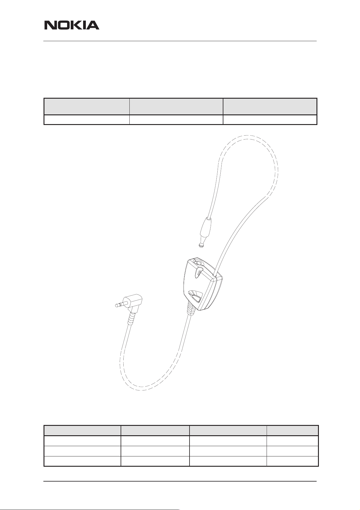
Exploded View of LPS-3
PAMS Technical Documentation
Assembly parts of LPS-3
ITEM Q’TY CODE DESCRIPTION VALUE, TYPE
1 0201489 Module lps-3
2 9780260 Loop set Cable LPS–3 DMJ00180
3 9451692 B–cover DMD05510
4 9451691 A–cover DMD05509
5 2 6290021 PT-screw 1,8x8 feznTX6
6 9451693 Battery lid DMD05507
7 9451694 Button DMD05511
8 9380750 Type label
Note: The torque of the screws is 0.35 Nm.
Page 12
Nokia Mobile Phones Ltd.
Issue 1 12/99
Page 13

-
PAMS Technical Documentation
Loopset LPS-3
Parts List of LPS-3
(Version 6.1) Code: 0201179
ITEM CODE DESCRIPTION VALUE TYPE
R001 1430784 Chip resistor 15 k 5 % 0.063 W 0402
R003 1430796 Chip resistor 47 k 5 % 0.063 W 0402
R004 1430778 Chip resistor 10 k 5 % 0.063 W 0402
R005 1430804 Chip resistor 100 k 5 % 0.063 W 0402
R006 1430792 Chip resistor 33 k 5 % 0.063 W 0402
R018 1430778 Chip resistor 10 k 5 % 0.063 W 0402
R020 1430796 Chip resistor 47 k 5 % 0.063 W 0402
R021 1430804 Chip resistor 100 k 5 % 0.063 W 0402
R024 1430792 Chip resistor 33 k 5 % 0.063 W 0402
R025 1430796 Chip resistor 47 k 5 % 0.063 W 0402
R026 1430122 Chip resistor 4.7 M 5 % 0.063 W 0603
R027 1430790 Chip resistor 27 k 5 % 0.063 W 0402
R028 1430804 Chip resistor 100 k 5 % 0.063 W 0402
R031 1430778 Chip resistor 10 k 5 % 0.063 W 0402
R032 1430804 Chip resistor 100 k 5 % 0.063 W 0402
R033 1430780 Chip resistor 12 k 5 % 0.063 W 0402
R034 1430784 Chip resistor 15 k 5 % 0.063 W 0402
R035 1430788 Chip resistor 22 k 5 % 0.063 W 0402
R036 1430778 Chip resistor 10 k 5 % 0.063 W 0402
R037 1430778 Chip resistor 10 k 5 % 0.063 W 0402
R039 1430804 Chip resistor 100 k 5 % 0.063 W 0402
R041 1430804 Chip resistor 100 k 5 % 0.063 W 0402
R042 1430812 Chip resistor 220 k 5 % 0.063 W 0402
R043 1430804 Chip resistor 100 k 5 % 0.063 W 0402
R044 1430778 Chip resistor 10 k 5 % 0.063 W 0402
R046 1430762 Chip resistor 2.2 k 5 % 0.063 W 0402
R047 1430804 Chip resistor 100 k 5 % 0.063 W 0402
R048 1430812 Chip resistor 220 k 5 % 0.063 W 0402
C002 2610003 Tantalum cap. 10 u 20 % 10 V
3.2x1.6x1.6
C005 2610003 Tantalum cap. 10 u 20 % 10 V
3.2x1.6x1.6
C006 2320779 Ceramic cap. 100 n 10 % 16 V 0603
C008 2610101 Tantalum cap. 22 u 20 % 3.5x2.8x1.9
C009 2320592 Ceramic cap. 2.2 n 5 % 50 V 0402
C010 2320546 Ceramic cap. 27 p 5 % 50 V 0402
C015 2320580 Ceramic cap. 680 p 5 % 50 V 0402
C017 2320580 Ceramic cap. 680 p 5 % 50 V 0402
C018 2320469 Ceramic cap. Y5 V 0603
C021 2320779 Ceramic cap. 100 n 10 % 16 V 0603
C022 2320592 Ceramic cap. 2.2 n 5 % 50 V 0402
C023 2320580 Ceramic cap. 680 p 5 % 50 V 0402
C024 2320107 Ceramic cap. 10 n 5 % 50 V 0603
Issue 1 12/99
Nokia Mobile Phones Ltd.
Page 13
Page 14

Loopset LPS-3
C025 2320546 Ceramic cap. 27 p 5 % 50 V 0402
C026 2320779 Ceramic cap. 100 n 10 % 16 V 0603
C027 2320779 Ceramic cap. 100 n 10 % 16 V 0603
C029 2320107 Ceramic cap. 10 n 5 % 50 V 0603
C030 2320107 Ceramic cap. 10 n 5 % 50 V 0603
C031 2320779 Ceramic cap. 100 n 10 % 16 V 0603
C033 2320546 Ceramic cap. 27 p 5 % 50 V 0402
C034 2320779 Ceramic cap. 100 n 10 % 16 V 0603
C035 2320592 Ceramic cap. 2.2 n 5 % 50 V 0402
C038 2320564 Ceramic cap. 150 p 5 % 50 V 0402
C039 2320469 Ceramic cap. Y5 V 0603
C040 2320469 Ceramic cap. Y5 V 0603
C041 2320779 Ceramic cap. 100 n 10 % 16 V 0603
C053 2320584 Ceramic cap. 1.0 n 5 % 50 V 0402
C221 2320779 Ceramic cap. 100 n 10 % 16 V 0603
C261 2320546 Ceramic cap. 27 p 5 % 50 V 0402
C262 2320546 Ceramic cap. 27 p 5 % 50 V 0402
B001 5140117 Cond.mic 45+–3DB 33PF 2K D5.8/9.D5.8/9.0
Z001 3640035 Filt z>450r/100m 0r7max 0.2a 0603 0603
Z002 3640035 Filt z>450r/100m 0r7max 0.2a 0603 0603
T001 3640073 Af–transformer for manual p&p smd SMD
V400 4219922 Transistor x 2 UM6
V401 4219922 Transistor x 2 UM6
V405 4219904 Transistor x 2 UMX1 npn 40 V SOT363
V406 4219908 Transistor x 2 SOT363
N003 4340379 IC, 2xop amp 2.7/3v ssoLMC6572BIMM SSOP8
N402 4340331 IC, Power amp. LM4862 P W SO8S
X100 5409067 SM, pin header 1x04 p1.25 1a s STR.
X200 5400125 SM, pcb conn 4mm f 90deg
6400039 Battery spring dmd03655 lps–1
9854251 PCB LPS1 28.2X33.1X1.0 M4 24/PA
PAMS Technical Documentation
Page 14
Nokia Mobile Phones Ltd.
Issue 1 12/99
 Loading...