

Nokia IP710 - Firewall, IP740 Installation Manual
IP700 Series Installation Guide
Part Number: N450436003 Rev B
April 2004

COPYRIGHT
© 2002 Nokia Corporation. All rights reserved.
Rights reserved under the copyright laws of the United States.
RESTRICTED RIGHTS LEGEND
Use, duplication, or disclosure by the United States Government is subject to restrictions as set forth in subparagraph
(c)(1)(ii) of the Rights in Technical Data and Computer Software clause at DFARS 252.227-7013. Notwithstanding any
other license agreement that may pertain to, or accompany the delivery of, this computer software, the rights of the
United States Government regarding its use, reproduction, and disclosure are as set forth in the Commercial Computer
Software-Restricted Rights clause at FAR 52.227-19.
IMPORTANT NOTE TO USERS
This software and hardware is provided by Nokia Corporation as is and any express or implied warranties, including,
but not limited to, implied warranties of merchantability and fitness for a particular purpose are disclaimed. In no event
shall Nokia, or its affiliates, subsidiaries or suppliers be liable for any direct, indirect, incidental, special, exemplary, or
consequential damages (including, but not limited to, procurement of substitute goods or services; loss of use, data,
or profits; or business interruption) however caused and on any theory of liability, whether in contract, strict liability, or
tort (including negligence or otherwise) arising in any way out of the use of this software, even if advised of the possibility of such damage. Nokia reserves the right to make changes without further notice to any products herein.
TRADEMARKS
Nokia is a registered trademark of Nokia Corporation. Other products mentioned in this document are trademarks or
registered trademarks of their respective holders.

Nokia Contact Information
Corporate Headquarters
Email info@iprg.nokia.com
Web Site http://www.nokia.com
Telephone 1-888-477-4566 or 1-65 0-625-2000
Fax 1-650-691-2170
Mail Address Nokia Inc.
313 Fairchild Drive
Mountain View, California
94043-2215 USA
Regional Contact Information
Americas
Nokia Inc.
313 Fairchild Drive
Mountain View, CA 94043-2215
USA
Tel: 1-877-997-9199
Outside USA and Canada: +1 512-437-7089
e-mail: info.ipnetworking_americas@nokia.com
Europe
Nokia House, Summit Avenue
Southwood, Farnborough
Hampshire GU14 ONG U.K
Asia-Pacific
Nokia Customer Support
Web Site: https://support.nokia.com/
Email: tac.support@nokia.com
Americas
Voice: 1-888-361-5030 or 1-613-271-6721
Fax: 1-613-271-8782
Europe
Voice: +44 (0) 125-286-8900
Fax: +44 (0) 125-286-5666
Asia-Pacific
Voice: +65-7232999
Fax: +65-7232897
Tel: 00800 5543 1816 or 1+44 (0) 8700 555 777
e-mail: info.ipnetworking_emea@nokia.com
Tel: +358 9 692 7156
e-mail: info.ipnetworking_apac@nokia.com


Contents
About This Guide . . . . . . . . . . . . . . . . . . . . . . . . . . . . . .11
About Nokia IP700 Series
Network Security Platforms. . . . . . . . . . . . . . 12
IP700 Series Documentation. . . . . . . . . . . . . . . . . . . 13
Structure of This Guide. . . . . . . . . . . . . . . . . . . . . . . 14
Conventions Used in This Guide . . . . . . . . . . . . . . . 16
CHAPTER 1 Overview . . . . . . . . . . . . . . . . . . . . . . . . . . . . . . . . . . . . . . 19
About the IP700 Series Platform. . . . . . . . . . . . . . . . 19
Site Requirements . . . . . . . . . . . . . . . . . . . . . . . . . . . 22
CHAPTER 2 Installing the IP700 Series Appliance. . . . . . . 23
Using DHCP to Configure the Appliance. . . . . . . . . 24
Using the Console Connection to Configure the
Appliance . . . . . . . . . . . . . . . . . . . . . . . . . . . . 27
Connecting Power and Turning the Power On . . . . . 28
Connecting to the Console . . . . . . . . . . . . . . . . . . . . 30
Monitoring the Appliance . . . . . . . . . . . . . . . . . . . . . 33
CHAPTER 3 Installing, Monitoring, and Replacing
Components. . . . . . . . . . . . . . . . . . . . . . . . . . . . . . . . . . . 35
Network Interface Card Preinstallation
Considerations . . . . . . . . . . . . . . . . . . . . . . . . 36
Installing a New Network Interface Card . . . . . . . . . 43
Monitoring Network Interface Cards . . . . . . . . . . . . 45
Removing a Network Interface Card . . . . . . . . . . . . 46
Replacing a Network Interface Card. . . . . . . . . . . . . 49
Installing a PCMCIA Modem. . . . . . . . . . . . . . . . . . 52
Monitoring and Replacing a Hard-Disk Drive Unit . 53
Replacing the Fan Tray. . . . . . . . . . . . . . . . . . . . . . . 59
IP700 Series Installation Guide 5

Contents
Monitoring and Replacing a Power Supply . . . . . . . . 61
Upgrading the Memory . . . . . . . . . . . . . . . . . . . . . . . 64
CHAPTER 4 Configuring and Monitoring the
IP700 Series Appliance
Entering the Hostname. . . . . . . . . . . . . . . . . . . . . . . .76
Entering the Passwords . . . . . . . . . . . . . . . . . . . . . . .76
Entering the Browser Type. . . . . . . . . . . . . . . . . . . . . 76
Entering Initial Interface Information . . . . . . . . . . . . 78
Confirming New System Setup Summary . . . . . . . . . 8 1
Using Voyager to Configure the Network Interfaces. 81
CHAPTER 5 Connecting to the Network . . . . . . . . . . . . . . . . . . .85
. . . . . . . . . . . . . . . . . . . . . . .75
Connecting to Ethernet Devices. . . . . . . . . . . . . . . . . 86
Connecting to V.35 or X.21 Devices . . . . . . . . . . . . . 91
Connecting to E1 (Built-in CSU/DSU) Devices . . . . 95
Connecting to T1 (Built-in CSU/DSU) Devices . . . . 99
Connecting to ATM Devices . . . . . . . . . . . . . . . . . .102
Connecting to Gigabit Ethernet Devices . . . . . . . . .104
Connecting to a Modem . . . . . . . . . . . . . . . . . . . . . .107
CHAPTER 6 Installing the Nokia Encryption Accelerator
Card
CHAPTER 7 Using the Boot Manager. . . . . . . . . . . . . . . . . . . . . 119
. . . . . . . . . . . . . . . . . . . . . . . . . . . . . . . . . . . . . . . . . . . 109
Installing the Encryption Accelerator Card . . . . . . . 110
Enabling the Encryption Accelerator Card. . . . . . . . 117
Variables . . . . . . . . . . . . . . . . . . . . . . . . . . . . . . . . . .120
Booting the System . . . . . . . . . . . . . . . . . . . . . . . . .128
Using the Boot Manager to Install IPSO . . . . . . . . .129
6 IP700 Series Installation Guide

Contents
Protecting the Boot Manager with a Password . . . . 130
Installing Boot Manager . . . . . . . . . . . . . . . . . . . . . 131
Upgrading Boot Manager . . . . . . . . . . . . . . . . . . . . 132
CHAPTER 8 Troubleshooting. . . . . . . . . . . . . . . . . . . . . . . . . . . . . . 133
General Troubleshooting Information. . . . . . . . . . . 133
CHAPTER 9 Using tcpdump. . . . . . . . . . . . . . . . . . . . . . . . . . . . . . . 147
tcpdump Command Basics . . . . . . . . . . . . . . . . . . . 148
Filtering Traffic With tcpdump . . . . . . . . . . . . . . . . 149
Saving tcpdump Results to a Local File . . . . . . . . . 150
CHAPTER 10 Tips for Installing, Configuring, and
Maintaining Your Appliance . . . . . . . . . . . . . . . . 153
APPENDIX A Technical Specifications . . . . . . . . . . . . . . . . . . . . 155
Physical . . . . . . . . . . . . . . . . . . . . . . . . . . . . . . . . . . 155
Environmental. . . . . . . . . . . . . . . . . . . . . . . . . . . . . 155
NIC Interfaces. . . . . . . . . . . . . . . . . . . . . . . . . . . . . 156
Space Requirements . . . . . . . . . . . . . . . . . . . . . . . . 157
APPENDIX B Compliance Information . . . . . . . . . . . . . . . . . . . . 159
Declaration of Conformity . . . . . . . . . . . . . . . . . . . 160
Compliance Statements. . . . . . . . . . . . . . . . . . . . . . 162
FCC Notice (US). . . . . . . . . . . . . . . . . . . . . . . . . . . 163
FCC Requirements (US). . . . . . . . . . . . . . . . . . . . . 164
Equipment Attachment Regulations (Canada) . . . . 166
IP700 Series Installation Guide 7

Contents
APPENDIX C General Public Licensed Software . . . . . . . . .167
GNU GENERAL PUBLIC LICENSE. . . . . . . . . . .168
APPENDIX D Warranty and Software License . . . . . . . . . . . . 171
APPENDIX E Glossary of Abbreviations . . . . . . . . . . . . . . . . . . .175
Index . . . . . . . . . . . . . . . . . . . . . . . . . . . . . . . . . . . . . . . . . .177
8 IP700 Series Installation Guide

Figures
Component Locations (Sample Configuration) . . . . . . . . . . . . . . . . . . . . . . . . . . 20
Back Panel View . . . . . . . . . . . . . . . . . . . . . . . . . . . . . . . . . . . . . . . . . . . . . . . . . 28
Component Location . . . . . . . . . . . . . . . . . . . . . . . . . . . . . . . . . . . . . . . . . . . . . . 31
Appliance Status LEDs. . . . . . . . . . . . . . . . . . . . . . . . . . . . . . . . . . . . . . . . . . . . . 33
Network Interface Card Bus Locations . . . . . . . . . . . . . . . . . . . . . . . . . . . . . . . . 36
Connecting to Gigabit Ethernet NICs for High Availability With a DMZ Port . 40
High Availability With a DMZ Environment . . . . . . . . . . . . . . . . . . . . . . . . . . . 41
Hard-Disk Drive Unit, Status LEDs, and Hot Swap Switch Locations . . . . . . . . 53
Power Switch Locations. . . . . . . . . . . . . . . . . . . . . . . . . . . . . . . . . . . . . . . . . . . . 55
Power Supply Status LED Locations. . . . . . . . . . . . . . . . . . . . . . . . . . . . . . . . . . 61
DIMM Socket Locations . . . . . . . . . . . . . . . . . . . . . . . . . . . . . . . . . . . . . . . . . . . 70
Pressing DIMMs Into DIMM Sockets . . . . . . . . . . . . . . . . . . . . . . . . . . . . . . . . . 72
Voyager Reference Access Points Example. . . . . . . . . . . . . . . . . . . . . . . . . . . . . 82
Built-in Ethernet Interface Front Panel Details . . . . . . . . . . . . . . . . . . . . . . . . . . 87
Typical Four-Port Ethernet Network Interface Card Front Panel Details . . . . . . 87
Output Connector for the Ethernet Cable. . . . . . . . . . . . . . . . . . . . . . . . . . . . . . . 89
Ethernet Crossover-Cable Pin Connections . . . . . . . . . . . . . . . . . . . . . . . . . . . . . 90
Typical Dual-Port V.35 or X.21 Network Interface Card Front Panel Details . . 91
Output Connector for the V.35 Cable. . . . . . . . . . . . . . . . . . . . . . . . . . . . . . . . . . 93
Output Connector for the X.21 Cable. . . . . . . . . . . . . . . . . . . . . . . . . . . . . . . . . . 94
Typical E1 Network Interface Card Front Panel Details . . . . . . . . . . . . . . . . . . . 96
Output Connector for the E1 Cable . . . . . . . . . . . . . . . . . . . . . . . . . . . . . . . . . . . 97
E1 Crossover Cable Pin Connections. . . . . . . . . . . . . . . . . . . . . . . . . . . . . . . . . . 98
8-pin female (host) . . . . . . . . . . . . . . . . . . . . . . . . . . . . . . . . . . . . . . . . . . . . . . . . 98
Typical Nokia T1 Network Interface Card Front Panel Details. . . . . . . . . . . . . 100
Output Connector for the T1 Cable . . . . . . . . . . . . . . . . . . . . . . . . . . . . . . . . . . 101
T1 Crossover Cable Pin Connections. . . . . . . . . . . . . . . . . . . . . . . . . . . . . . . . . 101
8-pin female (host) . . . . . . . . . . . . . . . . . . . . . . . . . . . . . . . . . . . . . . . . . . . . . . . 101
Typical ATM Network Interface Card Front Panel Details. . . . . . . . . . . . . . . . 102
Single-Port Gigabit Ethernet Network Interface Card Front Panel Details . . . . 105
Dual-Port Gigabit Ethernet Network Interface Card Front Panel Details . . . . . 105
Pin assignments for modem connections . . . . . . . . . . . . . . . . . . . . . . . . . . . . . . 107
IP700 Series Installation Guide 9

Figures
10 IP700 Series Installation Guide

About This Guide
This preface provides the following information:
• About Nokia IP700 Series Network Security Platforms (see page 12)
• IP700 Series Documentation (see page 13)
• Structure of This Guide (see page 14)
• Conventions Used in This Guide (see page 16)
IP700 Series Installation Guide 11

About This Guide
About Nokia IP700 Series Network Security
Platforms
The Nokia IP700 Series network security platforms (NSP) appliances,
also referred to as the IP700 Series appliances, add service-provider-class
reliability to the proven Nokia platform. The combination of world-class
routing, market-leading firewall software, high availability , and the fastest
packet-forwarding rate in a single package in the industry sets a new
standard for firewall and virtual private network (VPN) solutions.
Ideally suited to provide secure Internet connectivity , the IP710 and IP7 40
combine high-performance, high-availability IP routing with a complete
implementation of the Check Point VPN-1/FireWall-1® enterprise
security suite. Various network interface cards give you flexibility in
making your network connections. For high availability, IP700 Series
appliances allow you to hot swap network interface cards, hard-disk drive
units, power supplies, and fan trays.
You can manage IP700 Series appliances by using Voyager, a Nokia
Web-based management application, and Nokia Horizon Manager
software.
With Voyager, you can manage, monitor, and configure IP700 Series
appliances from any authorized location within the network by using a
standard Web browser. Voyager is preinstalled on the IP700 Series
appliance. For information about accessing Voya ger and the related
reference materials, see “Using Voyager to Configure the Network
Interfaces” on page 81.
The IP700 Series platform is fully supported by Nokia Horizon Manager
for secure image management, including:
• OS and application upgrades and licensing
• configuration-file backup and restore
• application installation
Nokia Horizon Manager allows you to manage all your NSPs and perform
image management actions on multiple platforms simultaneously.
12 IP700 Series Installation Guide

IP700 Series Documentation
The Nokia documentation set consists of Release Notes for the Nokia
software release you are running, the IP700 Series Installation Guide
(this document), a Voyager inline help feature, and the Voyager
Reference Guide (online).
You can find the Release Notes and the IP700 Series Installation Guide
in both HTML and PDF formats on the World Wide Web support site
(https://support.nokia.com/).
You can access inline help when you use Voyager. Inline help is the
context-sensitive information source for Voyager.
T o enable inline help for a specific subject, click the button next to the
subject.
Access the Voyager Reference Guide for tasks, examples, and more
information by pressing the
IP700 Series Documentation
DOC button.
You can order Check Point documentation from Nokia or download it
from the support site at https://support.nokia.com/.
IP700 Series Installation Guide 13

About This Guide
Structure of This Guide
This guide consists of the following chapters and appendixes:
• CHAPTER 1, Overview presents a general overview of the IP700
Series platform.
• CHAPTER 2, Installing the IP700 Series Appliance explains how to
physically connect the appliance to a network.
• CHAPTER 3, Installing, Monitoring, and Replacing Components
explains how to install, monitor, and replace network interface cards
and other components such as hard-disk drive units, power supplies,
fan units, and modems.
• CHAPTER 4, Configuring and Monitoring the IP700 Series
Appliance explains how to configure the appliance.
• CHAPTER 5, Connecting to the Network explains how to connect to
and use each of the supported network interface cards.
• CHAPTER 6, Installing the Nokia Encryption Accelerator Card
explains how to install and enable the accelerator card.
• CHAPTER 7, Using the Boot Manager explains how to use the boot
manager, which is part of the built-in IPSO software.
• CHAPTER 8, Troubleshooting discusses problems you might
encounter and proposes solutions to these problems.
• CHAPTER 9, Using tcpdump discusses the tcpdump utility, which
allows you to view traffic on a network.
• CHAPTER 10, Tips for Installing, Configuring, and Maintaining
Your Appliance provides a list of suggestions for installing,
configuring, and maintaining your appliance.
• APPENDIX A, Techn ical Specifications gives technical
specifications such as interface characteristics.
• APPENDIX B, Compliance Information includes compliance and
regulatory information.
14 IP700 Series Installation Guide

Structure of This Guide
• APPENDIX C, General Public Licensed Software provides
information about publicly licensed software that comes with the
appliance.
• APPENDIX D, Warranty and Software License contains Nokia
warranty and software license information.
• APPENDIX E, Glossary of Abbreviations provides definitions to
acronyms and initialisms used throughout the guide.
IP700 Series Installation Guide 15

About This Guide
Conventions Used in This Guide
This section describes the conventions used in text, examples, and
graphics.
Typeface/
Meaning
Italic
• Link, data entry location,
menu name, option name,
Web page, or Web-page
section name
• A command-line
placeholder
• An important word or
phrase
• Reference to a section or
document
SMALL CAPS
• Button to click with your
mouse
Courier New
Example
Click the Interfaces link.
Turn Internal Clock off.
To delete a file type rm filename.
This is the Overview chapter.
Click CONFIG.
• File names, directories
• Screen text presented by
the computer rather than
text you enter yourself
Courier New Bold
• Literal text that you enter
on the screen
16 IP700 Series Installation Guide
Hostname?
Type ser-s1p2 to configure the
interface.
!
Conventions Used in This Guide
WARNING: Shows critical information that, if ignored, could cause
injuries to you or to other people, damage to your equipment, or a
potential security breach.
Caution: Addresses actions that cause damage to equipment,
compromise the system, or would cause data loss.
NOTE: Calls special attention to important information.
IP700 Series Installation Guide 17

About This Guide
18 IP700 Series Installation Guide

CHAPTER 1 Overview
About the IP700 Series Platform
The Nokia IP700 Series platform combines the power of IPSO software
with your choice of applications. Each IP700 Series appliance consists of
components in three primary categories:
• Nokia hardware
• Selected network interface cards
• Designated software applications
IP700 Series Installation Guide 19
Chapter 1: Overview
6
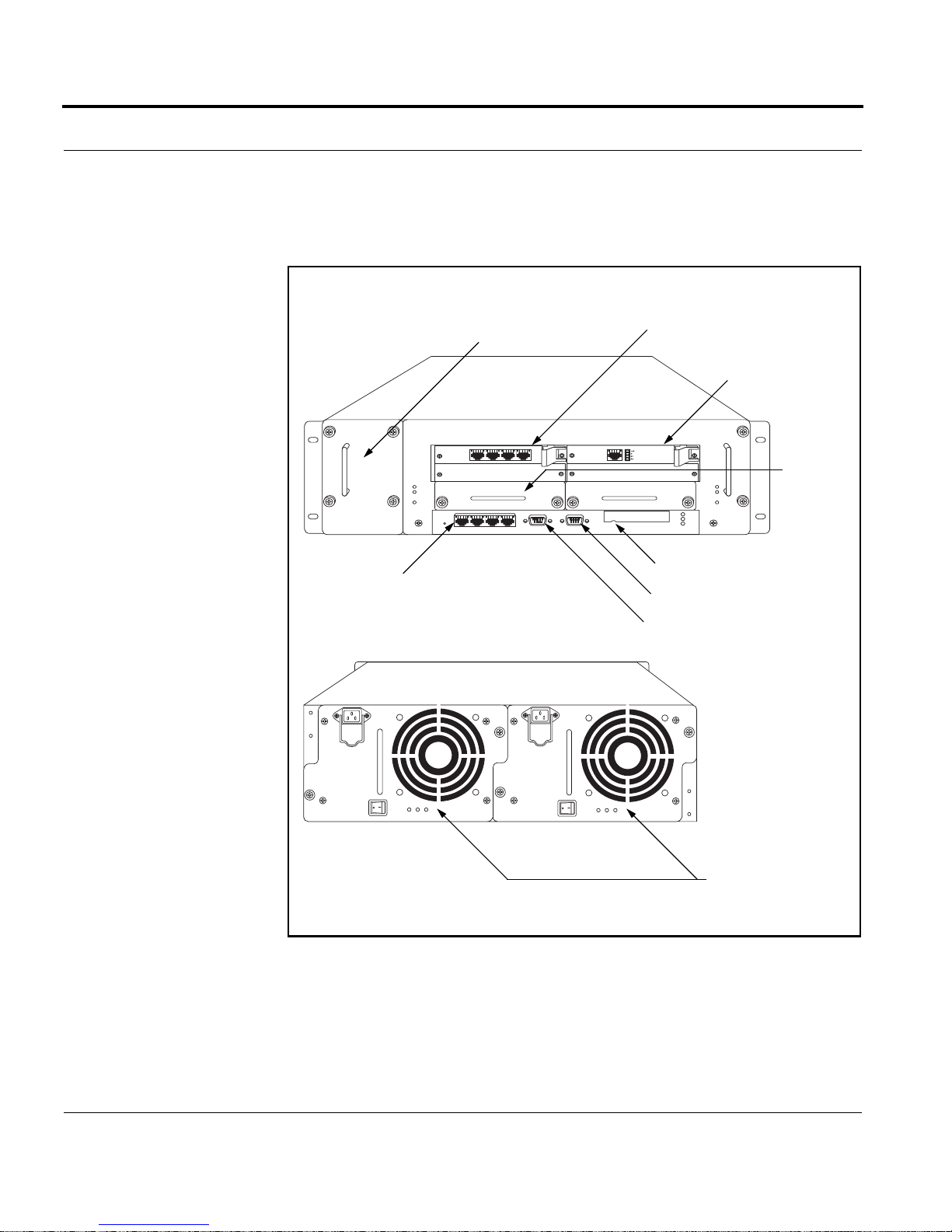
The following diagram shows component locations in a sample
configuration.
Component Locations (Sample Configuration)
Front View
Four-port Ethernet
(10/100 Mbps)
Rear View
Fan tray
Four-port Ethernet
(10/100 Mbps) card
T1 Card
Hard-Disk
Drive
00082
PCMCIA Slot
Modem port
Console port
The IP700 Series appliance can support two power supplies. In addition,
the IP700 Series appliance can house two disk drive units. However, the
feature of mirrored disk drives will only be supported when IPSO is
released with disk mirroring capabilities.
20 IP700 Series Installation Guide
0008
Power supplies

About the IP700 Series Platform
The IP700 Series appliance includes four compact PCI (cPCI) expansion
slots and two disk slots. The hard disk unit occupies at least one disk slot.
The four expansion slots support the cPCI network interface cards listed
in the following table.
For
information
about
using this
Interface
Serial Card
LAN Card
WAN Card
card, see:
Four-port Ethernet
√ page 86
(10 Mbps or 100 Mbps)
Dual-port V.35 or X.21 √ page 91
Single-port E1 with built-in
√ page 95
channel service unit/data service
unit (CSU/DSU)
Single-port T1 with built-in
√ page 99
channel service unit/data service
unit (CSU/DSU)
Single-port mode (ATM) √ page 102
Single-port gigabit Ethernet √ page 104
Dual-port gigabit Ethernet √ page 105
The IP700 Series appliance also includes a PCMCIA slot that supports
PCMCIA modems.
NOTE: Nokia products support only Nokia cards. The Nokia Customer
Support Department supports Nokia cards purchased either from Nokia
Inc. or approved resellers. Contact Nokia for sales or reseller information.
IP700 Series Installation Guide 21
Chapter 1: Overview
Site Requirements
Before you install the IP700 Series appliance, ensure that your computer
room or wiring closet conforms to the environmental specifications listed
in APPENDIX A, Technical Specifications.
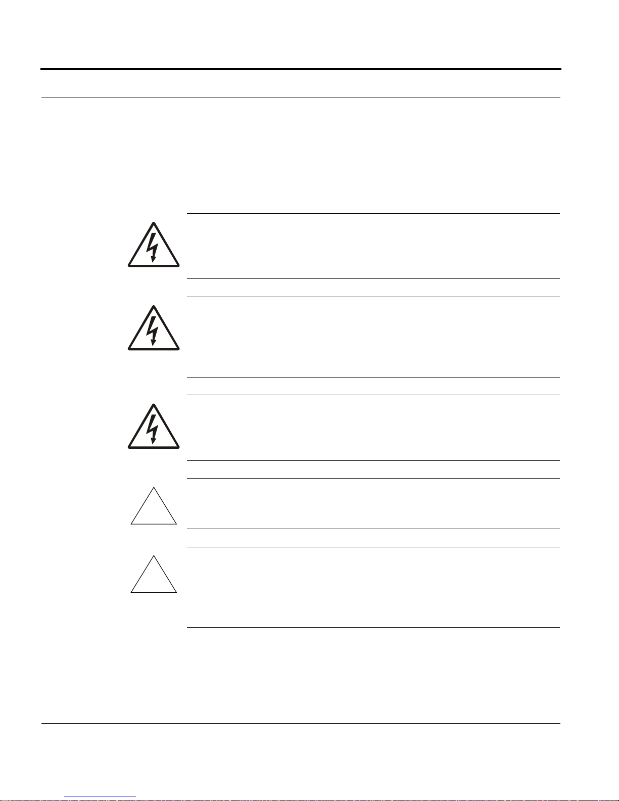
WARNING: Using controls, making adjustments in performance, or
following procedures that are not described in this document can
result in hazardous radiation exposure.
WARNING: An explosion can occur if the battery is incorrectly
placed. Replace only with the same or equivalent type battery
recommended by the manufacturer. Dispose of used batteries
according to the manufacturer's instructions.
!
!
WARNING: To reduce the risk of fire, electric shock, and injury
when you use telephone equipment, follow basic safety precautions.
Do not use the product near water.
Caution: Do not place objects over the ventilation holes on the IP700
Series appliance. The components might overheat and become damaged.
Caution: For IP700 Series appliances intended for shipment outside of
the United States, the cord might be optional. If a cord is not provided,
use a power cord rated at 6A, 250V, maximum 15 feet long, made of
HAR cordage and IEC fittings approved by the country of end use.
22 IP700 Series Installation Guide

CHAPTER 2 Installing the IP700 Series Appliance
This chapter describes how to install the Nokia IP700 Series appliance,
configure the system, connect it to your network, and monitor it. See
these topics for instructions to perform the tasks necessary for installing
or maintaining your appliance:
• Using DHCP to Configure the Appliance (see page 24)
• Using the Console Connection to Configure the Appliance (see
page 27)
• Connecting Power and Turning the Power On (see page 28)
• Connecting to the Console (see page 30)
• Monitoring the Appliance (see page 33)
Caution: Protect your IP700 Series appliance and other electronic
equipment from static discharge by making sure you are properly
!
IP700 Series Installation Guide 23
grounded before you touch any electronic components.

Chapter 2: Installing the IP700 Series Appliance
IPSO Version Requirements
To run an IP710 appliance, you must use IPSO v3.5 or higher. To run an
IP740 appliance, you must use IPSO v3.4 or higher.
Using DHCP to Configure the Appliance
You can use the built-in dynamic host configuration protocol (DHCP)
client to configure the system instead of using a console connection. This
feature allows a properly configured DHCP server to provide your IP700
Series appliance with the host name, IP address, and default route. You
can then use Voyager to reconfigure any of these settings. Once you do so,
Voyager preserve s the modified settings.
NOTE: DHCP is not used if configuration informa tion is already on the
appliance.
The DHCP server automatically sets the administrative password of the
IP700 Series appliance to password. To use DHCP to configure your
system, follow the instructions provided in the following topics:
• Configure the DHCP Server
• Run the DHCP Client on the IP700 Series Appliance
24 IP700 Series Installation Guide

Using DHCP to Configure the Appliance
Configure the DHCP Server
Before the DHCP server can provide an IP address to the IP700 Series
appliance, you must first map the server to the appliance by providing the
following:
• A host name you choose for the IP700 Series appliance
• The IP700 Series appliance serial number or the static MAC address
of the IP700 Series appliance NIC the DHCP server communicates
with.
The minimum IP address lease required is one year.
NOTE: Either the DHCP server must be on the same network as your
Nokia IP700 Series appliance, or DHCP/BOOTP relay must be
configured on the intermediate routers.
Following is an example of relevant DHCP configuration information:
ddns-update-style ad-hoc;
subnet 10.1.1.0 netmask 255.255.255 .0 {
# default gateway
option routers 10.1.1.1 ;
option subnet-mask
255.255.255.0;
option time-offset -8;
option domain-name-servers
24.5.207.179;
range dynamic-bootp 10.1.1. 20 10.1.1.100 ;
default-lease-time -1;
max-lease-time -1;
host IP710fixed {
# (optional) MAC address of the requesti ng
NIC
IP700 Series Installation Guide 25

Chapter 2: Installing the IP700 Series Appliance
hardware ethernet 00:a0:8e: 20:00:61;
# serial number of the box
option dhcp-client-identifi er "123456";
fixed-address 10.1.1.11;
option host-name "IP710";
Run the DHCP Client on the IP700 Series Appliance
NOTE: Do not perform this procedure unless you have configured an
appropriate DHCP server with configuration information for your IP700
Series appliance.
1. Connect a NIC in your IP700 Series appliance to your network.
If you specify a MAC address in the DHCP configuration
information, you must connect the NIC that has that address.
2. Turn the system on.
The DHCP client program in the IP700 Series appliance is started
automatically and the DHCP server provides the appropriate
configuration information. (This can require five to ten minutes.)
3. From a computer on the same network, ping the IP address that you
configured the DHCP server to provide to the IP700 Series appliance.
When you receive replies from ping, you can use Nokia Network
Voyager to connect to the system.
4. Connect to the IP700 Series appliance using Voyager and modify the
system configuration, as appropriate. T o connect using Voyager, enter
the IP address or host name of the system in your browser address
field.
26 IP700 Series Installation Guide

Using the Console Connection to Configure the Appliance
Using the Console Connection to Configure the
Appliance
If you use a console connection (a direct serial connection to the console
port) to configure your IP700 Series appliance, you are prompted for the
appropriate configuration settings the first time you turn it on. The first
prompt asks you to supply a host name. If you wait more than
approximately 30 seconds before you type anything in response to the
host name prompt, the DHCP client program starts automatically, and the
system might be provided a host name and IP address that is unknown to
you. (This could happen if there is a DHCP server on your network that is
configured to supply configuration information to any system that
requests it.)
In this situation, you will not be able to connect to the IP700 Series
appliance over the network (because you don’t know the appliance IP
address or host name). To resolve the problem, follow these steps:
1. Establish a console connection to the system.
2. Enter the following:
rm /config/active
or
mv /config/active /config/active.old
3. Reboot the IP700 Series appliance.
4. Respond to the configuration prompts in a timely manner.
IP700 Series Installation Guide 27

Chapter 2: Installing the IP700 Series Appliance
6
Connecting Power and Turning the Power On
NOTE: The IP700 Series appliance power supplies automatically detect
the input voltage (115VAC [90 to 132] or 220VAC [180 to 264]) and
configure themselves appropriately .
Back Panel View
Power Sockets
0008
Power Supply Switches
Perform the following steps for each power supply:
1. Connect the power cord securely into the power socket on the back of
the IP700 Series appliance.
Plug the other end of the cord into a three-wire grounded power strip
or wall outlet. If you are using two power supplies, a typical method
of connecting them is to plug one into an uninterruptable power
supply and the other into a wall outlet. Either power supply can safely
power the IP700 Series appliance.
2. Press the switch on the power supply to activate the IP700 Series
appliance.
28 IP700 Series Installation Guide

Connecting Power and Turning the Power On
The power supply fans are on when the power supply switch is turned
on. Verify that the power supply fans are running after you press the
switch.
You can check the LEDs on the back of each power supply to ensure
that they are both operating correctly. Most importantly, only the left
LED (Power OK) should be illuminated on each power supply. For
more information about the LEDs, see “Monitoring and Replacing a
Power Supply” on page 61.
3. If the power supply fans are not running, check the power supply cord
to make sure it is properly connected. If the fans are still not running
after this check, contact technical support. See “Nokia Contact
Information” on page 3 for more information.
IP700 Series Installation Guide 29

Chapter 2: Installing the IP700 Series Appliance
Connecting to the Console
The IP700 Series appliance requires a serial console connection for initial
configuration and occasional maintenance (cable included). The console
port on the IP700 Series appliance provides the following:
• RS-232 data terminal equipment (DTE) interface (cable included)
• 8 data bits
• No parity
• 1 stop bit
• 9600 bps
Once you initialize the system, the console connection is no longer
required.
NOTE: If you used DHCP to configure the system, you can skip these
instructions.
To conne ct to the console, follow these steps:
1. Select a console from the following list:
• Any standard VT100-compatible terminal
• A DOS or Windows computer or laptop running a terminal
emulation program
• A UNIX workstation
2. Connect a null-modem cable (console cable) to the local console port
on the front panel of the IP700 Series appliance.
NOTE: Use the left port; the right port is an auxiliary modem port.
30 IP700 Series Installation Guide
 Loading...