

Page 1

Product Overview
Ethernet bridge adapters
100BASE-T, E66210.32
10/100BASE-T, E66210.33
DN0610789
© Nokia Corporation
1 (14)
Page 2

Product Overview
The information in this document is subject to change without notice and describes only the
product defined i n the introduction of this documentation. This document is intended for the
use of Nokia's customers only for the purposes of the agreement under which the document is
submitted, and no part of it may be re pr o du c e d or tr an s mitted in any form or means wit hout
the prior written permission of Nokia. The document has been prepared to be used by
professional and properly trained personnel, and the customer assumes full responsibility
when using it. Nokia welco m es cu sto m er c omm e nts as pa rt of t h e process of continuous
development and imp r ovement of the docum entation.
The information or stat em e nts gi v e n in th is d oc um e nt co nc e rn i ng t he suitability, capacity, or
performance of the mentioned hardware or software products cannot be considered binding
but shall be defined in the ag r ee m ent m ade b etween Nokia and the customer. However,
Nokia has made all reasonable efforts to ensure that the instr uctions contained in the
document are adequate and free of material errors and omissions. Nokia will, if necessary,
explain issues which may not be covered by the do c u m ent.
Nokia's liability for any errors in the document is limited to the documentary correction of
errors. NOKIA WILL NOT BE RESPONSIBLE IN ANY EVENT FOR ERRORS IN THIS
DOCUMENT OR FOR ANY DAMAGES, INCIDENTAL OR CONSEQUENTIAL (INCLUDING
MONETARY LOSSES), th at mi ght ar is e f ro m t he use of this document or the information in it.
This document and the product it describes are considered protected by copyright according
to the applicable laws.
NOKIA logo is a registered tr ad em a rk of N ok ia C o r p or at i on.
Other product names mentioned in this document may be trademarks of their respective
companies, and they are mentioned for identification purposes only.
Copyright © Nokia Corporation 2006. All rights reserved.
2 (14) © Nokia Corporation
DN0610789
Page 3

Contents
Contents
1 Product description ...............................................................................4
2 Hardware installation instructions .......................................................7
2.1 Front panel...............................................................................................9
2.2 Cabling...................................................................................................11
3 Product features................................................................................... 12
3.1 Bridge.....................................................................................................12
3.2 LAN ........................................................................................................12
3.3 WAN.......................................................................................................13
3.4 Environmental ........................................................................................13
3.5 Modem requirements .............................................................................13
DN0610789
© Nokia Corporation
3 (14)
Page 4
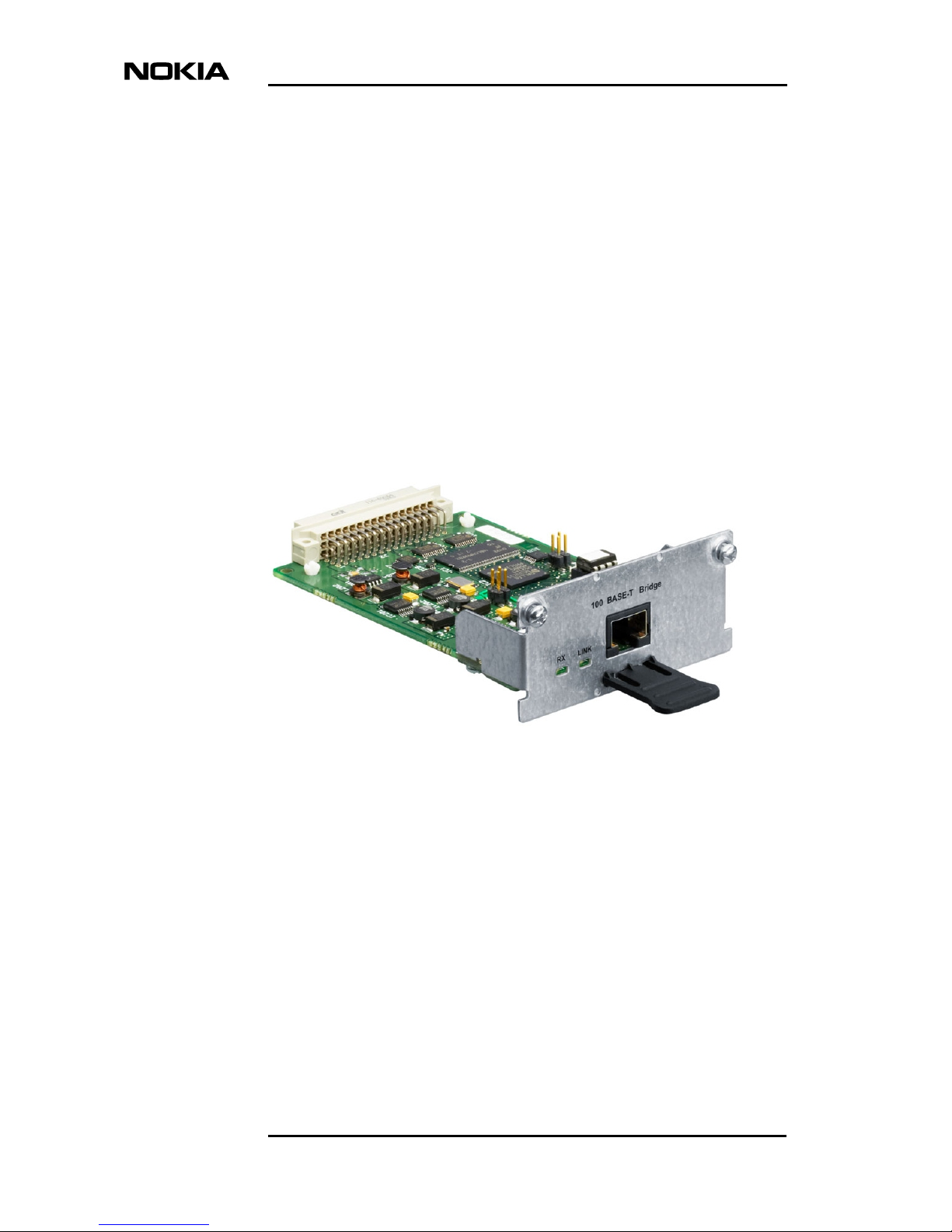
1 Product description
The Nokia ET-adapter is a plug-and-play Ethernet interface adapter for Dynanet
(DNT) modems. This Ethernet interface adapter can be installed to the adapter
port of a DNT modem.
Product Overview
Figure 1. ET adapter
The main function of the ET-adapter is to bridge two LANs over the WAN.
Ethernet frames received from the LAN are encapsulated inside the HDLC
frames and the HDLC frames are sent to the WAN according the serial data
speed of WAN. The WAN interface of ET-adapter is connecte d to the interfa ce
port of DNT-series modem. Packets that are received from WAN are
decapsulated from HDLC frame and then sent to Ethernet interface of an ETadapter.
WAN transmission rate and used time slots are selected fr om the modem end.
The modem can indicate adapter type and Ethernet link status. All other settings
4 (14) © Nokia Corporation
DN0610789
Page 5

Product description
are fixed. There are three selectable Ethernet interface se ttings i n E662 10.3 3:
10BASE half and full duplex and 100BASE full duplex.
The data path and main components of ET-adapter are described in the block
diagram below.
WAN
Euro
Figure 2. Block diagr am
ET-adapter is compatible to virtual LANs and 802.1Q VLAN tags are
forwarded transparently over the WAN. Using virtual LANs several subnets can
be combinated to the one Ethernet link, but only if also Ethernet switches
support VLANs.
100BASE-T
Power
3,3V / 1,8V
HDLC
Ethernet
switch
ISEPROM
2048x8
Bridge
DS33ZII
SDRMA
4x1Mx32
ET-Adapter 100 BASE-T
MII
PHY
LXT971
Link integrity & activity
100BASE-T
10/100
RJ-45
Ethernet
switch
LAN
LEDs
VLAN1
Figure 3. VLAN
DN0610789
© Nokia Corporation
VLAN2
VLAN2
VLAN1
5 (14)
Page 6

Product Overview
Ethernet bridge adapter makes rate adaption and it can be connected to
10BASE-T ET-adapter or DYNANET EIU.
100BASE-T 10BASE-T 10BASE-T
Figure 4. E66210.32 c on n ected
7 OCTETS
1 OCTET
6 OCTETS
6 OCTETS
2 OCTETS
46-1500 OCTETS
4 OCTETS
LSB MSB
PREAMBLE
SFD
DESTINATION ADDRESS
SOURCE ADDRESS
LENGTH/TYPE
MAC CLIENT DATA
PAD
FRAME CHECK SEQUENCE
0
b
Bits within
frame transmitted left to right
7
b
Octets within
frame transmitted
top to bottom
All octets except preamble
and SFD are bridged
transparently over the WAN
Figure 5. MAC frame
The figure above describes the standard Ethernet frame without VLAN tag.
Standard maximum frame length is 1518 bytes. The ET-adapter supports frames
included in 802.1Q VLAN tag. 1522 bytes long frames are forwarded from
LAN to WAN.
6 (14) © Nokia Corporation
DN0610789
Page 7

Hardware installation instructions
2 Hardware installation instructions
Ethernet
connector
Modern
connector
DN0610789
NR3 Pin 1
Figure 6. ET Adapter card E66210.33
© Nokia Corporation
7 (14)
Page 8

Product Overview
Table 1. E66210.33 bridging
Link speed 10BASE 10BASE 100BASE
Duplex status Half Full Full
Closed pins 1-2 3-4 5-6
LED 100 Off Off On
LED HD On Off Off
Installing E66210.32
Figure 7. Installing the adapter
1. Switch off the modem power, plug the ET-adapter into the slot and
tighten two scr e w s . T hen switch on the modem. The ET-adapter is ready
to use.
Installing E66210.33
1. Select Ethernet interface configuration and close pins of NR3 according
to Table 1.
2. Switch off the modem power, plug the ET-adapter into the slot and
tighten two scr e w s . T hen switch on the mod em. The ET-ada pt er is ready
to use.
8 (14) © Nokia Corporation
DN0610789
Page 9

2.1 Front panel
RX LINK
Figure 8. Front panel
Hardware installation instructions
100 BASE-T Bridge
RX displays receive status: LED blinks every time when an Ethernet packet is
received from the LAN.
LINK displays link status: LED is lit when cable is connected to another
Ethernet equipment and the link is up. Link status is also shown at the DNT
modem: if the link is down there is no incoming signal alarm.
DN0610789
© Nokia Corporation
9 (14)
Page 10

Product Overview
10/100 BASE-T Bridge
Speed
10
100
100
Duplex
Half
Full
Full
100 HD
Off
Off Off
RX LINK 100 HD
Figure 9. Front panel E66210.33
RX displays receive status. LED blinks every time when an Ethernet packet is
received from the LAN.
LINK displays link status. LED is lit when cable is connected to another
Ethernet equipment and the link is up. Link status is also shown at the DNT
modem: if the link is down there is no incoming signal alarm.
100 displays speed status. LED is lit when the ET-adapter is configured to
100BASE mode, otherwise the adapter is configured to 10BASE mode.
On
OffOn
HD displays duplex status. LED is lit when the ET-adapter is configured to
half duplex mode, otherwise the adapter is configured to full duplex mode.
10 (14) © Nokia Corporation
DN0610789
Page 11

Hardware installation instructions
Figure 10. Ethernet connector and pin numbering
2.2 Cabling
ET-adapter is connected to the network adapter with a direct Ethernet cable.
The maximum length of a category 5 cable is 100m. If the ET-adapter is
connected to the Ethernet hub or switch then use a cross-connected Ethernet
cable.
Pin Signal Direction
1 Rx+ input
2 Rx- input
3 Tx+ output
4 Not connected
5 Not connected
6 Tx- output
7 Not connected
8 Not connected
Figure 11. Direct cabling
Ensure that the Ethernet port that is connected to ET-adapter has the same
configuration as the ET-adapter. Port speed and duplex stat u s h a ve t o be t he
same at both Ethernet ports. It is not recommended to use auto-negotiation
option. Port configuration should always be fixed.
DN0610789
© Nokia Corporation
11 (14)
Page 12

3 Product features
3.1 Bridge
All received frames are forwared transparently to th e WAN.
Receive buffer size 1728 MAC frames
Transmit buffer size 320 MAC frames
Product Overview
Receive buffer is queue for data that was received from the Ethernet (LAN) to
be transmitted to the HDLC (WAN).
Transmit buffer is for data that was received from the WAN to be transmitted
to the Ethernet.
Receive buffer high watermark 1632 MAC frames
Receive buffer low watermark 1536 MAC frames
If the receive buffer size exceeds higher watermark, the ET adapter will send a
pause frame to LAN. Pause frame is sent every time when a frame is received
from LAN until the low watermak is reached. The pause frame is sent to a
multicast destination address 01-80-C2-00-00-01. Pause time parameter of
pause frame is 80 slots. Pause frame is sent only when full duplex mode is
selected.
3.2 LAN
Selectable configuration 10 Mbps and half duplex
10 Mbps and full duplex
12 (14) © Nokia Corporation
100 Mbps and full duplex
DN0610789
Page 13

Maximum transfer unit 2016 bytes
Any frame larger than the maximum transfer unit (MTU) value will be rejected.
The frame size includes destination address, source address, ty pe, length, data
and CRC. Standard Ethernet frame maximum length is 1518 bytes (destination
address 6 bytes + source address 6 bytes + type 2 bytes + data 1500 bytes +
CRC 4 bytes).
Cable UTP CAT5, maximum cable le ngth
3.3 WAN
HDLC RFC1662
FCS 16 bits
Product features
100m
Idle signal flag 7E (0111 1110)
Idle flags are sent continously to WAN when there are no packets in the receive
buffer. Two idle flags are sent between every HDLC packet.
Line speed n x 64 kbps (n = 1…32)
3.4 Environmental
Climatic
EMC: EN 300 386
Power consumption: 800 mW
Operation: EN 300 019, class 3.2
Transport: EN 300 019, class 2.3
Storage: EN 300 019, class 1.2
3.5 Modem requirements
The ET-adapter can be installed to the follwing modems. The modem adapter
type is displayed as V.35 or Ethernet E66210.32 depending on the DNT modem
software version.
DN0610789
© Nokia Corporation
13 (14)
Page 14

Product Overview
DNT2M-sp T65620
DNT2M-mp T65630
DNT2Mi-sp T65670
DNT2Mi-mp T65680
DNT2M-G-sp T65650
DNT2M-G-mp T65660
14 (14) © Nokia Corporation
DN0610789
 Loading...