

Page 1

Nokia Customer Care
4 — Service Tools and Service
Concepts
Issue 1 COMPANY CONFIDENTIAL Page 4 –1
Copyright © 2006 Nokia. All rights reserved.
Page 2

RM-88
Nokia Customer Care Service Tools and Service Concepts
(This page left intentionally blank.)
Page 4 –2 COMPANY CONFIDENTIAL Issue 1
Copyright © 2006 Nokia. All rights reserved.
Page 3

RM-88
Service Tools and Service Concepts Nokia Customer Care
Table of Contents
Service tools............................................................................................................................................................4–5
AC-34...................................................................................................................................................................4–5
CA-31D................................................................................................................................................................4–5
CA-56RS...............................................................................................................................................................4–5
CU-4.....................................................................................................................................................................4–6
DKE-2...................................................................................................................................................................4–7
FLS-4S..................................................................................................................................................................4–7
FPS-10.................................................................................................................................................................4–7
FS-5.....................................................................................................................................................................4–8
MJ-67...................................................................................................................................................................4–8
RJ-86...................................................................................................................................................................4–8
SA-82...................................................................................................................................................................4–9
SRT-6...................................................................................................................................................................4–9
SS-46.................................................................................................................................................................4–10
SS-62.................................................................................................................................................................4–10
SS-76.................................................................................................................................................................4–10
Service concepts...................................................................................................................................................4–11
Flash concept with FPS-10..............................................................................................................................4–11
MJ-67 module jig concept...............................................................................................................................4–12
POS (Point of Sale) flash concept...................................................................................................................4–13
Service concept for RF testing and RF/BB tuning.........................................................................................4–14
CU-4 flash concept with FPS-10......................................................................................................................4–15
RF testing and BB testing/tuning..................................................................................................................4–16
List of Tables
Table 7 Attenuation table for MJ-67.....................................................................................................................4–8
Table 8 Attenuation table for antenna coupler SA-82........................................................................................4–9
List of Figures
Figure 28 Basic flash concept with FPS-10.........................................................................................................4–11
Figure 29 MJ-67 module jig service concept......................................................................................................4–12
Figure 30 POS flash concept................................................................................................................................4–13
Figure 31 Service concept for RF testing and RF/BB tuning.............................................................................4–14
Figure 32 CU-4 flash concept with FPS-10..........................................................................................................4–15
Figure 33 RF testing concept and BB testing/tuning........................................................................................4–16
Issue 1 COMPANY CONFIDENTIAL Page 4 –3
Copyright © 2006 Nokia. All rights reserved.
Page 4

RM-88
Nokia Customer Care Service Tools and Service Concepts
(This page left intentionally blank.)
Page 4 –4 COMPANY CONFIDENTIAL Issue 1
Copyright © 2006 Nokia. All rights reserved.
Page 5
RM-88
Service Tools and Service Concepts Nokia Customer Care
Service tools
The table below gives a short overview of service tools that can be used for testing, error analysis and repair
of product RM-88, refer to various concepts.
AC-34 Universal power
supply
Universal power supply
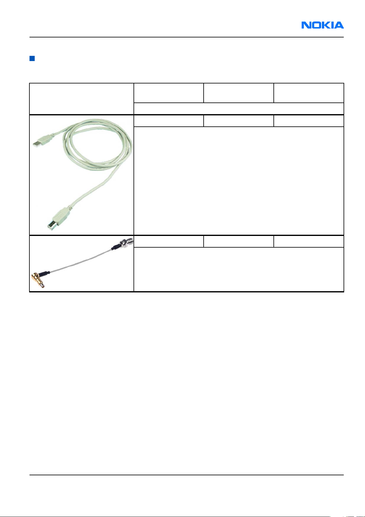
CA-31D USB cable
The CA-31D USB cable is used to connect FPS-10 or FPS-11 to a PC. It is
included in the FPS-10 and FPS-11 sales packages.
CA-56RS RF cable Small RF cable that is used for RF tuning with MJ-67 module jig.
Issue 1 COMPANY CONFIDENTIAL Page 4 –5
Copyright © 2006 Nokia. All rights reserved.
Page 6

RM-88
Nokia Customer Care Service Tools and Service Concepts
CU-4 Control unit CU-4 is a general service tool used with a module jig and/or a flash
adapter. It requires an external 12 V power supply.
The unit has the following features:
• software controlled via USB
• EM calibration function
• Forwards FBUS/Flashbus traffic to/from terminal
• Forwards USB traffic to/from terminal
• software controlled BSI values
• regulated VBATT voltage
• 2 x USB2.0 connector (Hub)
• FBUS and USB connections supported
When using CU-4, note the special order of connecting cables and
other service equipment:
Instructions
1 Connect a service tool (jig, flash adapter) to CU-4.
2 Connect CU-4 to your PC with a USB cable.
3 Connect supply voltage (12 V)
4 Connect an FBUS cable (if necessary).
5 Start Phoenix service software.
Note: Phoenix enables CU-4 regulators via USB when it is
started.
Reconnecting the power supply requires a Phoenix restart.
Page 4 –6 COMPANY CONFIDENTIAL Issue 1
Copyright © 2006 Nokia. All rights reserved.
Page 7

RM-88
Service Tools and Service Concepts Nokia Customer Care
DKE-2 Mini-USB cable USB to mini-USB connector cable.
FLS-4S Flash device FLS-4S is a dongle and flash device incorporated into one package,
developed specifically for POS use.
FPS-10 Flash prommer FPS-10 interfaces with:
• PC
• Control unit
• Flash adapter
• Smart card
FPS-10 flash prommer features:
• Flash functionality for BB5 and DCT-4 terminals
• Smart Card reader for SX-2 or SX-4
• USB traffic forwarding
• USB to FBUS/Flashbus conversion
• LAN to FBUS/Flashbus and USB conversion
• Vusb output switchable by PC command
FPS-10 sales package includes:
• FPS-10 prommer
• Power Supply with 5 country specific cords
• USB cable
Issue 1 COMPANY CONFIDENTIAL Page 4 –7
Copyright © 2006 Nokia. All rights reserved.
Page 8

RM-88
Nokia Customer Care Service Tools and Service Concepts
FS-5 Product specific
adapter
RM-88/RM-89 specific adapter.
MJ-67 Module jig RM-88/RM-89 specific module jig.
•
Table 7 Attenuation table for MJ-67
System Channel Tx/Rx-att. (dB)
GSM 850 128 0.2
190 0.1
251 0.1
GSM 900 975 0.1
38 0.1
124 0.2
GSM 1800 512 0.3
698 0.2
885 0.1
GSM 1900 512 0.5
700 0.6
810 0.8
Measured with Universal Radio Communication Tester CMU-200.
Note: Tx-attenuation tolerance is +/- 0.5dB
Rx-attenuation tolerance is +/- 1.0 dB
RJ-86 Soldering jig RM-88/RM-89 specific soldering jig.
Page 4 –8 COMPANY CONFIDENTIAL Issue 1
Copyright © 2006 Nokia. All rights reserved.
Page 9

RM-88
Service Tools and Service Concepts Nokia Customer Care
SA-82 Flash adapter
antenna coupler
RM-88/RM-89 specific flash adapter antenna coupler.
• Flash adapter antenna coupler SA-82 attenuation table for NOKIA
E62, measured with Universal Radio Communication Tester
CMU-200.
Table 8 Attenuation table for antenna coupler SA-82
System Channel Tx-att. (dB) Rx-att. (dB)
GSM 850 128 5.8 4
190 5.3 3
251 5.3 3
GSM 900 975 5.8 4
38 5 4
124 5 4
GSM 1800 512 7.7 6
698 7.4 6
885 7.2 5
GSM 1900 512 7.9 6
700 6.2 6
810 5.6 6
Note: Tx-attenuation tolerance is +/-0.5 dB.
Rx-attenuation tolerance is +/-1.0dB.
SRT-6 Opening tool SRT-6 is used to open phone covers and B-to-B connectors.
Issue 1 COMPANY CONFIDENTIAL Page 4 –9
Copyright © 2006 Nokia. All rights reserved.
Page 10

RM-88
Nokia Customer Care Service Tools and Service Concepts
SS-46 Interface adapter SS-46 acts as an interface adapter between the flash adapter and
FPS-10.
SS-62 Generic flash adapter
base for BB5
• generic base for flash adapters and couplers
• SS-62 equipped with a clip interlock system
• provides standardised interface towards Control Unit
• provides RF connection using galvanic connector or coupler
• multiplexing between USB and FBUS media, controlled by VUSB
SS-76 Domesheet assembly
jig
Page 4 –10 COMPANY CONFIDENTIAL Issue 1
Copyright © 2006 Nokia. All rights reserved.
Page 11

RM-88
Service Tools and Service Concepts Nokia Customer Care
Service concepts
Flash concept with FPS-10
Figure 28 Basic flash concept with FPS-10
Description Type
FS-5 Flash adapter
SS-46 Interface adapter
CA-35S Power cable
XCS-4 Modular cable
Standard USB cable
FPS-10 Flash prommer box
Standard USB cable
PKD-1 SW security device
Issue 1 COMPANY CONFIDENTIAL Page 4 –11
Copyright © 2006 Nokia. All rights reserved.
Page 12

RM-88
Nokia Customer Care Service Tools and Service Concepts
MJ-67 module jig concept
Figure 29 MJ-67 module jig service concept
Type Description
MJ-67 Module jig
CU-4 Control unit
FPS-10 Flash prommer box
SX-4 Smart card
XCS-4 Modular cable
PCS-1 DC power cable
Standard USB cable
Standard USB cable
GPIB control cable
XRS-6 RF cable
PKD-1 SW security device
RF shield box
Page 4 –12 COMPANY CONFIDENTIAL Issue 1
Copyright © 2006 Nokia. All rights reserved.
Page 13

RM-88
Service Tools and Service Concepts Nokia Customer Care
POS (Point of Sale) flash concept
Figure 30 POS flash concept
Type Description
CA-53 USB connectivity cable
FLS-5 POS flash device
ACP-8 Power adapter
Issue 1 COMPANY CONFIDENTIAL Page 4 –13
Copyright © 2006 Nokia. All rights reserved.
Page 14

RM-88
Nokia Customer Care Service Tools and Service Concepts
Service concept for RF testing and RF/BB tuning
Figure 31 Service concept for RF testing and RF/BB tuning
Description Type
MJ-67 Module jig
CU-4 Control unit
Standard USB cable
PCS-1 DC power cable
Standard USB cable + smart card reader
SX-4 Smart card
XRS-6 RF cable
GPIB control cable
PKD-1 SW security device
RF shield box
Page 4 –14 COMPANY CONFIDENTIAL Issue 1
Copyright © 2006 Nokia. All rights reserved.
Page 15

RM-88
Service Tools and Service Concepts Nokia Customer Care
CU-4 flash concept with FPS-10
Figure 32 CU-4 flash concept with FPS-10
Note: FPS-8 concept can also be used for flashing.
Description Type
SS-62/FS-5 Flash adapter
CU-4 Control unit
XCS-4 Modular cable
PCS-1 Power cable
FPS-10 Flash prommer box
Standard USB cable
Standard USB cable
PKD-1 SW security device
Issue 1 COMPANY CONFIDENTIAL Page 4 –15
Copyright © 2006 Nokia. All rights reserved.
Page 16

RM-88
Nokia Customer Care Service Tools and Service Concepts
RF testing and BB testing/tuning
Figure 33 RF testing concept and BB testing/tuning
Type Description
SS-62/FS-5 Flash adapter
CU-4 Control unit
SA-82 RF coupler
PCS-1 Power cable
XCS-4 Modular cable
Standard USB cable
Standard USB cable + smart card reader
SX-4 Smart card
GPIB control cable
XRS-6 RF cable
PKD-1 SW security device
RF shield box
Page 4 –16 COMPANY CONFIDENTIAL Issue 1
Copyright © 2006 Nokia. All rights reserved.
 Loading...