

Page 1

Nokia Customer Care
Service Manual
RM-89 (Nokia E61)
Mobile Terminal
Part No: 9248152 (Issue 1)
COMPANY CONFIDENTIAL
Copyright © 2006 Nokia. All rights reserved.
Page 2

RM-89
Nokia Customer Care Amendment Record Sheet
Amendment Record Sheet
Amendment No Date Inserted By Comments
Issue 1 04/2006 J-PH
Page ii COMPANY CONFIDENTIAL Issue 1
Copyright © 2006 Nokia. All rights reserved.
Page 3

RM-89
Copyright Nokia Customer Care
Copyright
Copyright © 2006 Nokia. All rights reserved.
Reproduction, transfer, distribution or storage of part or all of the contents in this document in any form
without the prior written permission of Nokia is prohibited.
Nokia, Nokia Connecting People, and Nokia X and Y are trademarks or registered trademarks of Nokia
Corporation. Other product and company names mentioned herein may be trademarks or tradenames of
their respective owners.
Nokia operates a policy of continuous development. Nokia reserves the right to make changes and
improvements to any of the products described in this document without prior notice.
Under no circumstances shall Nokia be responsible for any loss of data or income or any special, incidental,
consequential or indirect damages howsoever caused.
The contents of this document are provided "as is". Except as required by applicable law, no warranties of
any kind, either express or implied, including, but not limited to, the implied warranties of merchantability
and fitness for a particular purpose, are made in relation to the accuracy, reliability or contents of this
document. Nokia reserves the right to revise this document or withdraw it at any time without prior notice.
The availability of particular products may vary by region.
IMPORTANT
This document is intended for use by qualified service personnel only.
Issue 1 COMPANY CONFIDENTIAL Page iii
Copyright © 2006 Nokia. All rights reserved.
Page 4

RM-89
Nokia Customer Care Warnings and cautions
Warnings and cautions
Warnings
• IF THE DEVICE CAN BE INSTALLED IN A VEHICLE, CARE MUST BE TAKEN ON INSTALLATION IN VEHICLES FITTED
WITH ELECTRONIC ENGINE MANAGEMENT SYSTEMS AND ANTI-SKID BRAKING SYSTEMS. UNDER CERTAIN FAULT
CONDITIONS, EMITTED RF ENERGY CAN AFFECT THEIR OPERATION. IF NECESSARY, CONSULT THE VEHICLE DEALER/
MANUFACTURER TO DETERMINE THE IMMUNITY OF VEHICLE ELECTRONIC SYSTEMS TO RF ENERGY.
• THE PRODUCT MUST NOT BE OPERATED IN AREAS LIKELY TO CONTAIN POTENTIALLY EXPLOSIVE ATMOSPHERES,
FOR EXAMPLE, PETROL STATIONS (SERVICE STATIONS), BLASTING AREAS ETC.
• OPERATION OF ANY RADIO TRANSMITTING EQUIPMENT, INCLUDING CELLULAR TELEPHONES, MAY INTERFERE
WITH THE FUNCTIONALITY OF INADEQUATELY PROTECTED MEDICAL DEVICES. CONSULT A PHYSICIAN OR THE
MANUFACTURER OF THE MEDICAL DEVICE IF YOU HAVE ANY QUESTIONS. OTHER ELECTRONIC EQUIPMENT MAY
ALSO BE SUBJECT TO INTERFERENCE.
• BEFORE MAKING ANY TEST CONNECTIONS, MAKE SURE YOU HAVE SWITCHED OFF ALL EQUIPMENT.
Cautions
• Servicing and alignment must be undertaken by qualified personnel only.
• Ensure all work is carried out at an anti-static workstation and that an anti-static wrist strap is worn.
• Ensure solder, wire, or foreign matter does not enter the telephone as damage may result.
• Use only approved components as specified in the parts list.
• Ensure all components, modules, screws and insulators are correctly re-fitted after servicing and
alignment.
• Ensure all cables and wires are repositioned correctly.
• Never test a mobile phone WCDMA transmitter with full Tx power, if there is no possibility to perform the
measurements in a good performance RF-shielded room. Even low power WCDMA transmitters may disturb
nearby WCDMA networks and cause problems to 3G cellular phone communication in a wide area.
• During testing never activate the GSM or WCDMA transmitter without a proper antenna load, otherwise
GSM or WCDMA PA may be damaged.
Page iv COMPANY CONFIDENTIAL Issue 1
Copyright © 2006 Nokia. All rights reserved.
Page 5

RM-89
ESD protection Nokia Customer Care
ESD protection
Nokia requires that service points have sufficient ESD protection (against static electricity) when servicing
the phone.
Any product of which the covers are removed must be handled with ESD protection. The SIM card can be
replaced without ESD protection if the product is otherwise ready for use.
To replace the covers ESD protection must be applied.
All electronic parts of the product are susceptible to ESD. Resistors, too, can be damaged by static electricity
discharge.
All ESD sensitive parts must be packed in metallized protective bags during shipping and handling outside
any ESD Protected Area (EPA).
Every repair action involving opening the product or handling the product components must be done under
ESD protection.
ESD protected spare part packages MUST NOT be opened/closed out of an ESD Protected Area.
For more information and local requirements about ESD protection and ESD Protected Area, contact your local
Nokia After Market Services representative.
Issue 1 COMPANY CONFIDENTIAL Page v
Copyright © 2006 Nokia. All rights reserved.
Page 6

RM-89
Nokia Customer Care Care and maintenance
Care and maintenance
This product is of superior design and craftsmanship and should be treated with care. The suggestions below
will help you to fulfil any warranty obligations and to enjoy this product for many years.
• Keep the phone and all its parts and accessories out of the reach of small children.
• Keep the phone dry. Precipitation, humidity and all types of liquids or moisture can contain minerals that
will corrode electronic circuits.
• Do not use or store the phone in dusty, dirty areas. Its moving parts can be damaged.
• Do not store the phone in hot areas. High temperatures can shorten the life of electronic devices, damage
batteries, and warp or melt certain plastics.
• Do not store the phone in cold areas. When it warms up (to its normal temperature), moisture can form
inside, which may damage electronic circuit boards.
• Do not drop, knock or shake the phone. Rough handling can break internal circuit boards.
• Do not use harsh chemicals, cleaning solvents, or strong detergents to clean the phone.
• Do not paint the phone. Paint can clog the moving parts and prevent proper operation.
• Use only the supplied or an approved replacement antenna. Unauthorised antennas, modifications or
attachments could damage the phone and may violate regulations governing radio devices.
All of the above suggestions apply equally to the product, battery, charger or any accessory.
Page vi COMPANY CONFIDENTIAL Issue 1
Copyright © 2006 Nokia. All rights reserved.
Page 7

RM-89
Company Policy Nokia Customer Care
Company Policy
Our policy is of continuous development; details of all technical modifications will be included with service
bulletins.
While every endeavour has been made to ensure the accuracy of this document, some errors may exist. If
any errors are found by the reader, NOKIA MOBILE PHONES Business Group should be notified in writing/email.
Please state:
• Title of the Document + Issue Number/Date of publication
• Latest Amendment Number (if applicable)
• Page(s) and/or Figure(s) in error
Please send to:
NOKIA CORPORATION
Nokia Mobile Phones Business Group
Nokia Customer Care
PO Box 86
FIN-24101 SALO
Finland
E-mail: Service.Manuals@nokia.com
Issue 1 COMPANY CONFIDENTIAL Page vii
Copyright © 2006 Nokia. All rights reserved.
Page 8

RM-89
Nokia Customer Care Battery information
Battery information
Note: A new battery's full performance is achieved only after two or three complete charge and
discharge cycles!
The battery can be charged and discharged hundreds of times but it will eventually wear out. When the
operating time (talk-time and standby time) is noticeably shorter than normal, it is time to buy a new battery.
Use only batteries approved by the phone manufacturer and recharge the battery only with the chargers
approved by the manufacturer. Unplug the charger when not in use. Do not leave the battery connected to
a charger for longer than a week, since overcharging may shorten its lifetime. If left unused a fully charged
battery will discharge itself over time.
Temperature extremes can affect the ability of your battery to charge.
For good operation times with Ni-Cd/NiMh batteries, discharge the battery from time to time by leaving the
product switched on until it turns itself off (or by using the battery discharge facility of any approved accessory
available for the product). Do not attempt to discharge the battery by any other means.
Use the battery only for its intended purpose.
Never use any charger or battery which is damaged.
Do not short-circuit the battery. Accidental short-circuiting can occur when a metallic object (coin, clip or
pen) causes direct connection of the + and - terminals of the battery (metal strips on the battery) for example
when you carry a spare battery in your pocket or purse. Short-circuiting the terminals may damage the battery
or the connecting object.
Leaving the battery in hot or cold places, such as in a closed car in summer or winter conditions, will reduce
the capacity and lifetime of the battery. Always try to keep the battery between 15°C and 25°C (59°F and 77°
F). A phone with a hot or cold battery may temporarily not work, even when the battery is fully charged.
Batteries' performance is particularly limited in temperatures well below freezing.
Do not dispose of batteries in a fire!
Dispose of batteries according to local regulations (e.g. recycling). Do not dispose as household waste.
Page viii COMPANY CONFIDENTIAL Issue 1
Copyright © 2006 Nokia. All rights reserved.
Page 9

RM-89
Nokia E61 Service Manual Structure Nokia Customer Care
Nokia E61 Service Manual Structure
1 General Information
2 Parts Lists and Component Layouts
3 Service Software Instructions
4 Service Tools and Service Concepts
5 Disassembly / Reassembly Instructions
6 BB Troubleshooting and Manual Tuning Guide
7 RF Troubleshooting and Manual Tuning Guide
8 System Module
9 Schematics
Issue 1 COMPANY CONFIDENTIAL Page ix
Copyright © 2006 Nokia. All rights reserved.
Page 10

RM-89
Nokia Customer Care Nokia E61 Service Manual Structure
(This page left intentionally blank.)
Page x COMPANY CONFIDENTIAL Issue 1
Copyright © 2006 Nokia. All rights reserved.
Page 11
Nokia Customer Care
1 — General Information
Issue 1 COMPANY CONFIDENTIAL Page 1 –1
Copyright © 2006 Nokia. All rights reserved.
Page 12

RM-89
Nokia Customer Care General Information
(This page left intentionally blank.)
Page 1 –2 COMPANY CONFIDENTIAL Issue 1
Copyright © 2006 Nokia. All rights reserved.
Page 13

RM-89
General Information Nokia Customer Care
Table of Contents
RM-89 product selection........................................................................................................................................1–5
RM-89 product features and sales package.........................................................................................................1–5
Product and module list........................................................................................................................................1–6
Mobile enhancements............................................................................................................................................1–7
Technical specifications.........................................................................................................................................1–9
Transceiver general specifications..................................................................................................................1–9
Main RF characteristics for GSM850/900/1800/1900 and WCDMA1900/2100 phones...............................1–9
Battery endurance...........................................................................................................................................1–10
Environmental conditions..............................................................................................................................1–10
List of Tables
Table 1 Audio..........................................................................................................................................................1–7
Table 2 Car...............................................................................................................................................................1–7
Table 3 Carrying......................................................................................................................................................1–8
Table 4 Data............................................................................................................................................................1–8
Table 5 Imaging......................................................................................................................................................1–8
Table 6 Messaging..................................................................................................................................................1–8
Table 7 Power.........................................................................................................................................................1–8
List of Figures
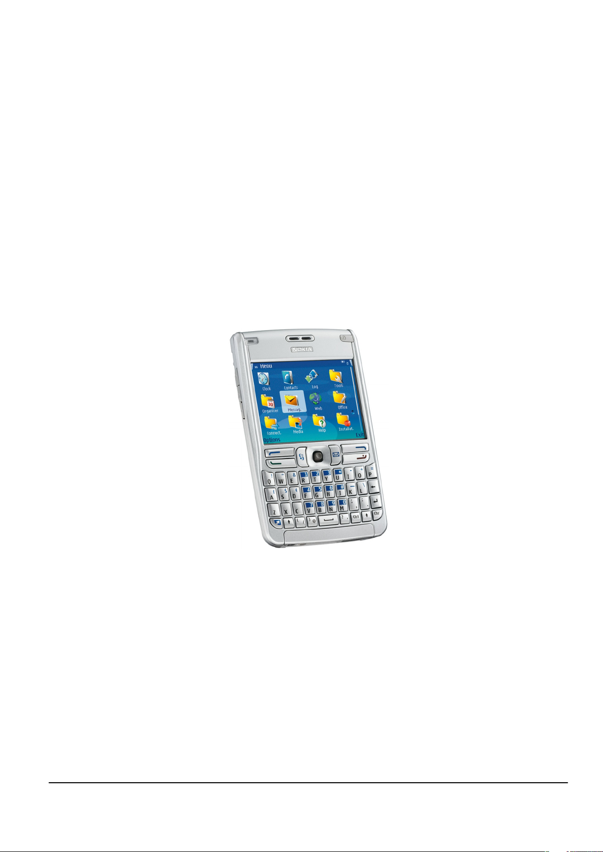
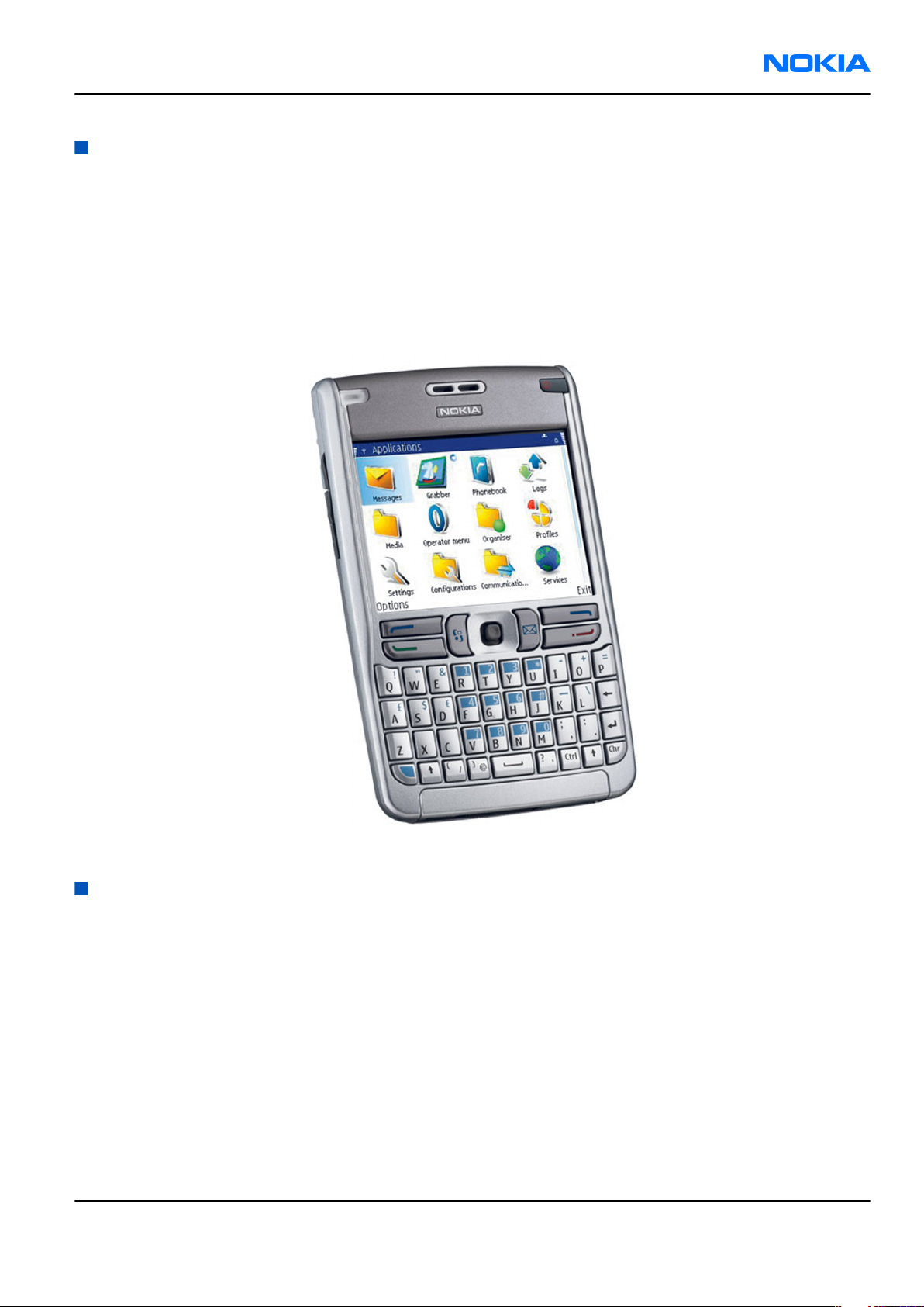
Figure 1 View of RM-89..........................................................................................................................................1–5
Issue 1 COMPANY CONFIDENTIAL Page 1 –3
Copyright © 2006 Nokia. All rights reserved.
Page 14

RM-89
Nokia Customer Care General Information
(This page left intentionally blank.)
Page 1 –4 COMPANY CONFIDENTIAL Issue 1
Copyright © 2006 Nokia. All rights reserved.
Page 15
RM-89
General Information Nokia Customer Care
RM-89 product selection
Nokia RM-89 is a WCDMA/GSM dual mode handportable phone, supporting WCDMA 2100 (UMTS) and EGSM
850/900/1800/1900 bands.
The MMS implementation follows the OMA MMS standard release 1.2.
WAP 2.0 compatible browser supports XHTML Mobile Profile (MP) and uses a TCP/IP stack to communicate
with a gateway in network.
RM-89 uses Symbian 9.1a operating system and supports also MIDP Java 2.0 & CLDC1.1, providing a good
platform for 3rd party applications.
Figure 1 View of RM-89
RM-89 product features and sales package
Bearers & transport
• WCDMA2100 Max DL=384kbps UL=384kbps, simultaneous voice & packet data
• GSM Quadband World Phone E850/900/1800/1900 EGPRS (class B, Multislot class 11)
Software platform
• SW platform: Nokia Series 60 rel 3.0
Connectivity
• Bluetooth (Headset & Handsfree profiles, BIP, GOP)
• MiniSD Card
• Pop-Port™ interface with USB
Issue 1 COMPANY CONFIDENTIAL Page 1 –5
Copyright © 2006 Nokia. All rights reserved.
Page 16
RM-89
Nokia Customer Care General Information
• PC Suite connectivity with USB & Bluetooth
• WLAN 802.11g
Productivity
• SMS, MMS and email
• MS Word, PowerPoint , Excel and Adobe PDF viewers
• PIM (Calendar & Contacts)
• Internet browser
• Video streaming (3GPP)
• Push to Talk
• Logs (last calls , timers and history list)
• Instant messaging
•
JavaTM MIDP 2.0, CLDC 1.13D API, PIM API, File access API
• MP3
• Data Transfer
• Settings Wizard/Access Point Configurator
Sales package
• Transceiver RM-89
• BL-5L Li-ion Battery Cell
• AC-4 Charger
• All-in-one User Guide (warranty card + accessory info + getting started sheet + invitational module for Club
Nokia )
• CD-ROM
• Headset HS-5
• USB Cable DKU-2
• CA-44
• Memory card Mini SD 64MB
• Application leaflet
• Quickstart guide
• Carrying case CP-111
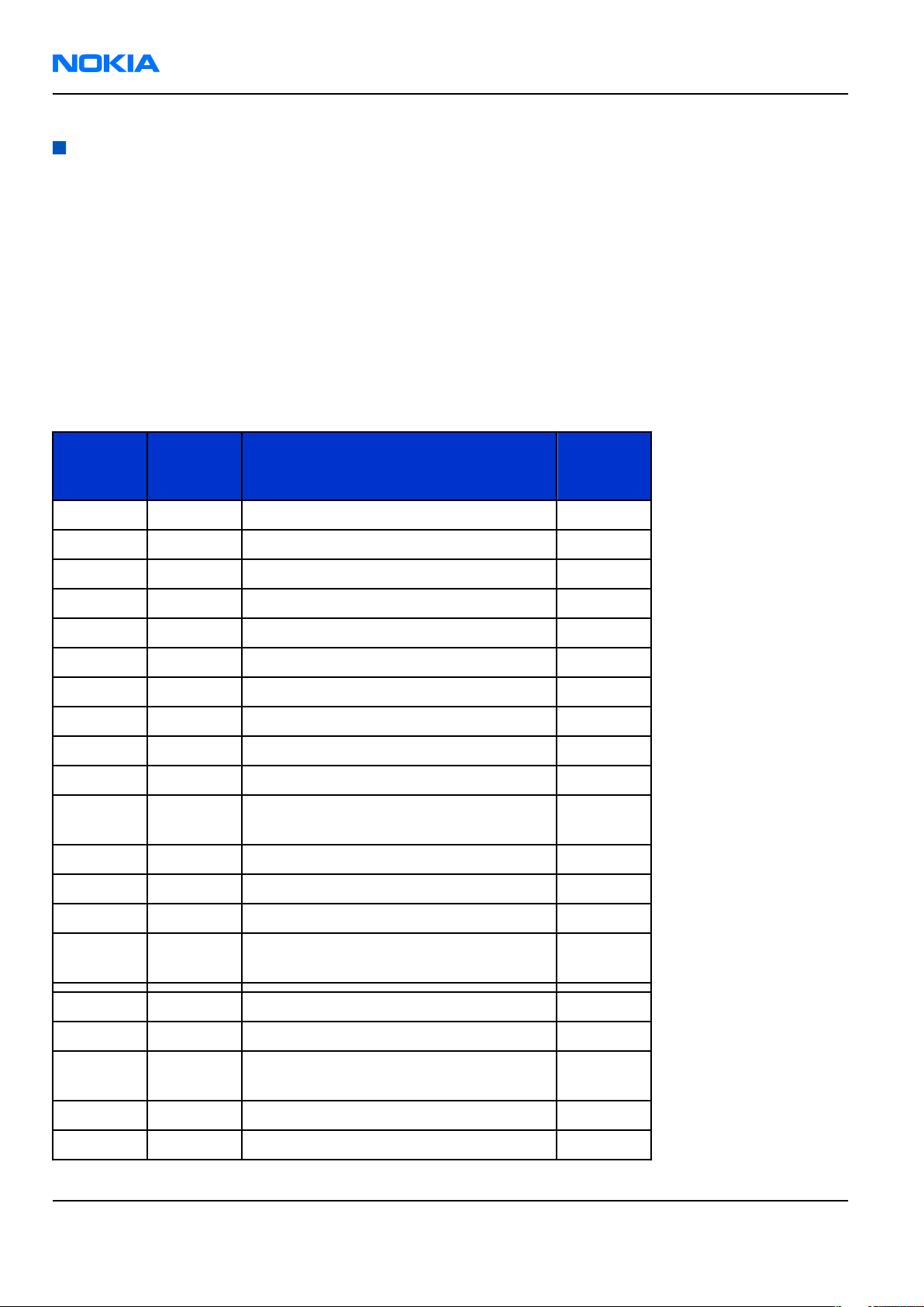
Product and module list
Module name Type code Notes
System/RF Module 1NF Main PWB with components
EL-Dome sheet
Chassis Assy
Display Module
Keyboard
A-cover Assy
Page 1 –6 COMPANY CONFIDENTIAL Issue 1
Copyright © 2006 Nokia. All rights reserved.
Page 17
RM-89
General Information Nokia Customer Care
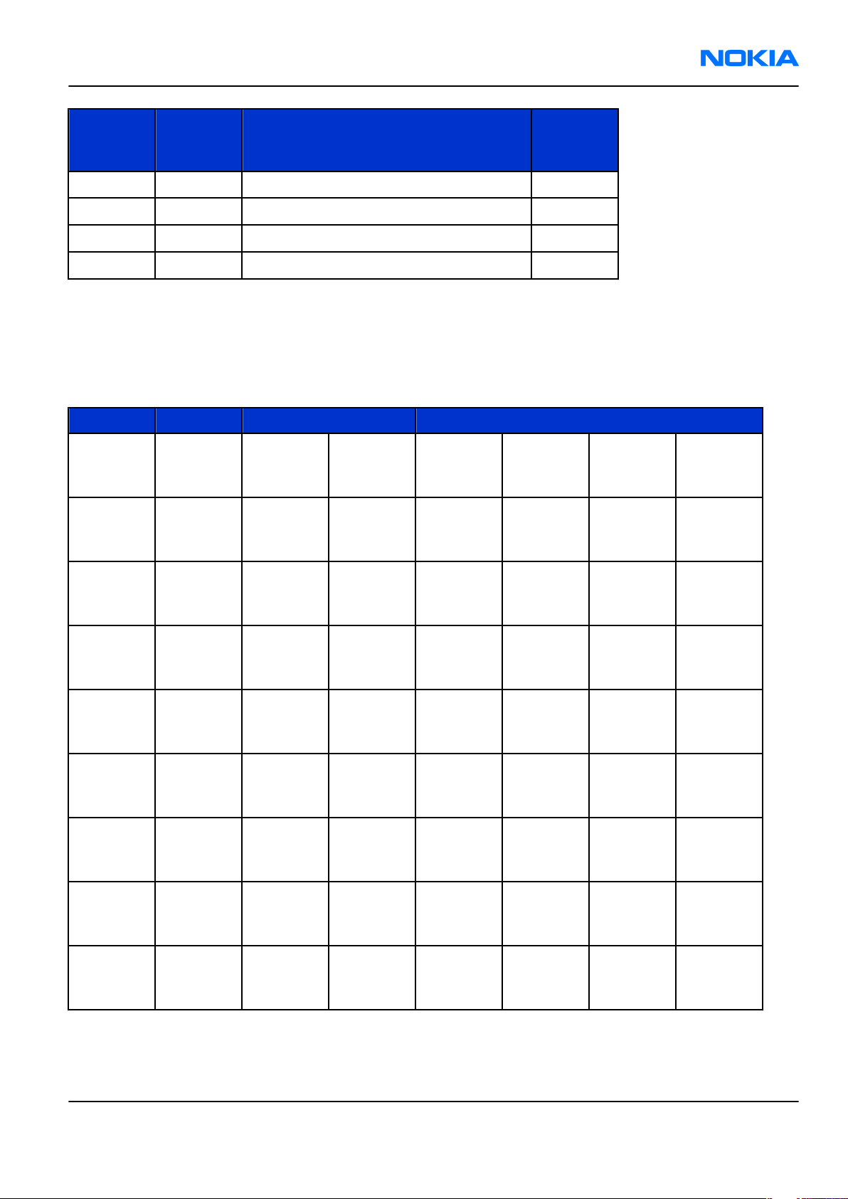
Module name Type code Notes
SW Module
Mobile enhancements
Table 1 Audio
Enhancement Type
Boom headset HDB-4
Fashion stereo headset HS-3
HS-31
Headset HS-5
Stereo headset HDS-3
Classic stereo headset HS-23
Display headset HS-6
FM radio headset HS-2R
Wireless headset HDW-3
HS-36W
HS-37W
HS-11W
HS-26W
Wireless boom headset HS-4W
Wireless clip-on headset HS-21W
Wireless image headset HS-13W
Loopset LPS-4
TTY adapter HDA-9
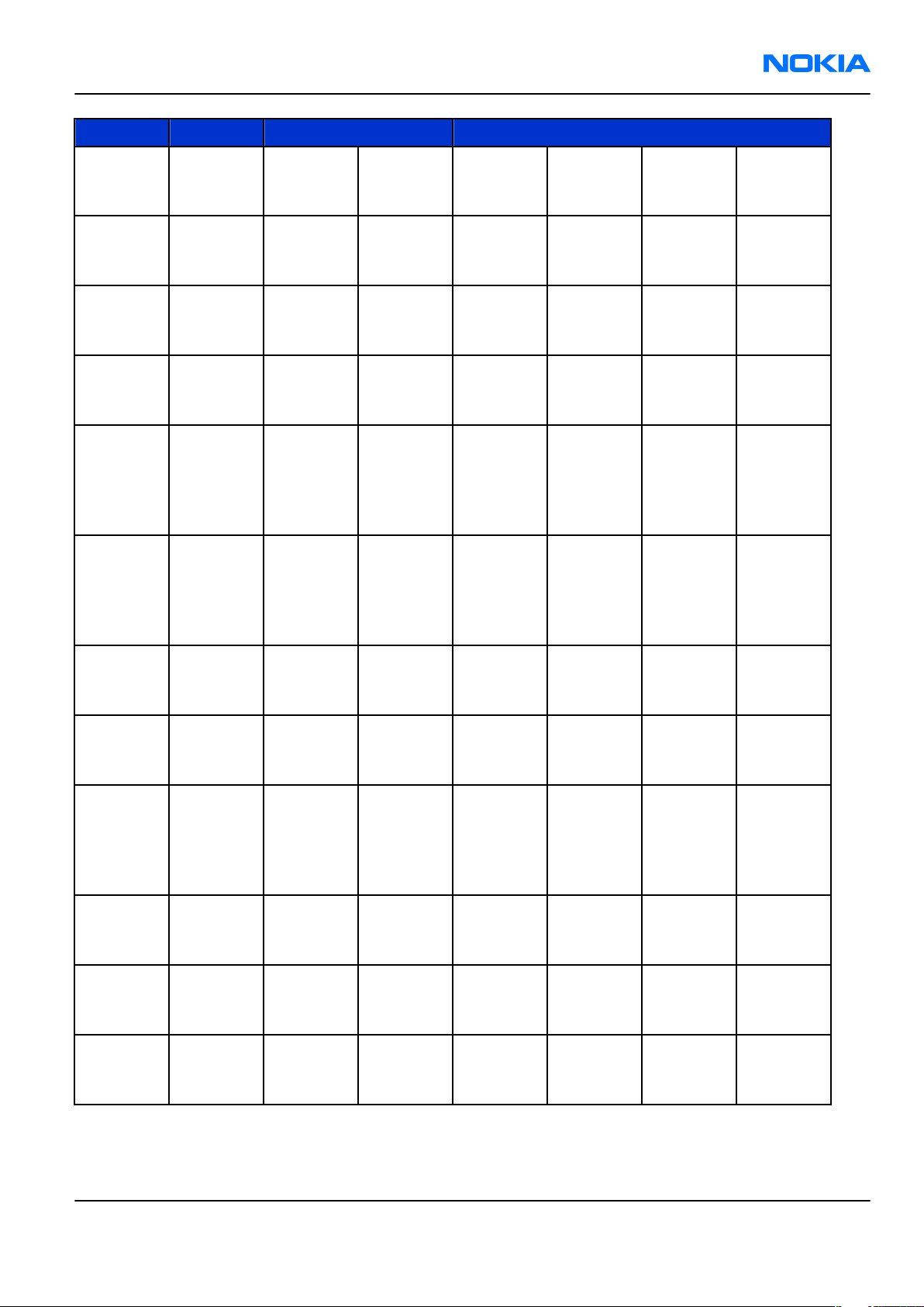
Table 2 Car
Enhancement Type
Wireless car kit CK-1W
Advanced car kit CK-7W
CK-10
Car kit phone N616
Wireless plug-in car handsfree HF-6W
Mobile charger DC-4
Mobile holder CR-47
Nokia Converter for Car Kit Cark-91
Headrest handsfree BHF-3
Issue 1 COMPANY CONFIDENTIAL Page 1 –7
Copyright © 2006 Nokia. All rights reserved.
Page 18
RM-89
Nokia Customer Care General Information
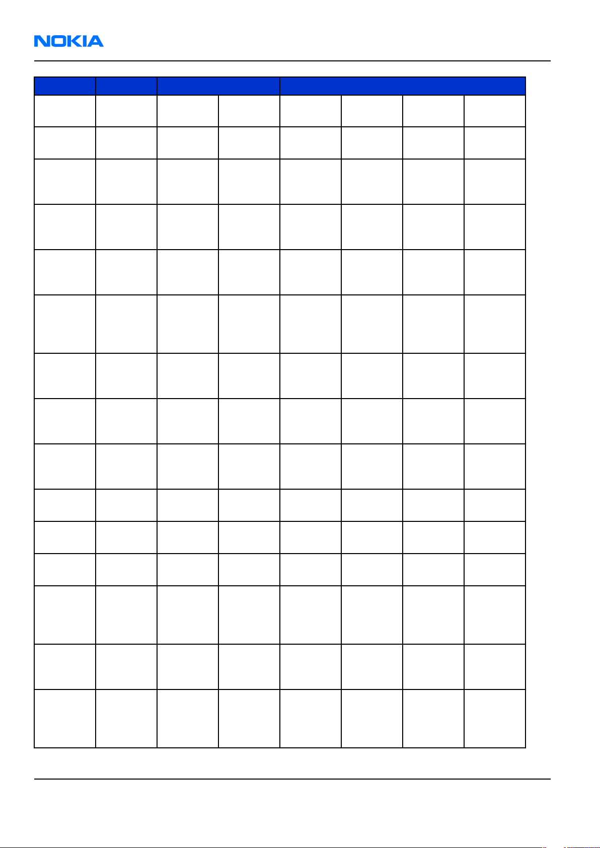
Enhancement Type
Plug-in car handsfree HF-3
Table 3 Carrying
Enhancement Type
Carrying case CP-111
Table 4 Data
Enhancement Type
Connectivity cable CA-53
Wireless GPS module LD-1W
MiniSD card 64 MB
MiniSD card 128 MB
MiniSD card 256 MB
MiniSD card 512 MB
Table 5 Imaging
Enhancement Type
Nokia image album PD-1
Nokia remote camera PT-6
Table 6 Messaging
Enhancement Type
Wireless keyboard SU-8W
Table 7 Power
Enhancement Type
Battery BP-5L
Travel charger AC-4
Compact charger AC-3
Charger adapter CA-44
Page 1 –8 COMPANY CONFIDENTIAL Issue 1
Copyright © 2006 Nokia. All rights reserved.
Page 19
RM-89
General Information Nokia Customer Care
Technical specifications
Transceiver general specifications
Unit Dimensions (L x W x T) Weight (g)
Transceiver with BP-5L
1500mAh li-ion battery
back
117.1 x 69.7 x 17.8 / 13.3mm144 (including BP-5L
battery)
Volume (cm3)
103.4
Main RF characteristics for GSM850/900/1800/1900 and WCDMA1900/2100 phones
Parameter Unit
Cellular system GSM850, EGSM900, GSM1800/1900, WCDMA1900 or
WCDMA2100
Rx frequency band GSM850: 869 - 894MHz
EGSM900: 925 - 960 MHz
GSM1800: 1805 - 1880 MHz
GSM1900: 1930 - 1990 MHz
WCDMA1900: 1930-1990MHz
WCDMA2100: 2110 - 2170 MHz
Tx frequency band GSM850: 824 - 849MHz
EGSM900: 880 - 915 MHz
GSM1800: 1710 - 1785 MHz
GSM1900: 1850 - 1910 MHz
WCDMA1900: 1850-1910MHz
WCDMA2100: 1920 - 1980 MHz
Output power GSM850: +5 ...+33dBm/3.2mW ... 2W
GSM900: +5 … +33dBm/3.2mW … 2W
GSM1800: +0 … +30dBm/1.0mW … 1W
GSM1900: +0 … +30dBm/1.0mW … 1W
WCDMA -50 … 24 dBm
Number of RF channels GSM850: 124
GSM900: 174
GSM1800: 374
GSM1900: 299
Channel spacing 200 kHz
Issue 1 COMPANY CONFIDENTIAL Page 1 –9
Copyright © 2006 Nokia. All rights reserved.
Page 20
RM-89
Nokia Customer Care General Information
Parameter Unit
Number of Tx power levels
GSM850: 15
GSM900: 15
GSM1800: 16
GSM1900: 16
Battery endurance
Battery Capacity (mAh) Talk time Stand-by
BP-5L 1500 up to 6 hrs up to 12 days
Charging times
ACP-4
2 h 10 min
Environmental conditions
Environmental condition Ambient temperature Notes
Normal operation
Reduced performance
Intermittent operation
No operation or storage
Charging allowed
Long term storage conditions
-15oC...+55oC
-25oC...-15oC
+55oC...+70oC
-40oC...-15oC
+70oC...+85 oC
<-40oC...>+85oC
-25oC...+50oC
0oC...+85oC
Specifications fulfilled
Operational for shorts periods
only
Operation not guaranteed but an
attempt to operate does not
damage the phone.
No storage or operation: an
attempt may damage the phone.
Page 1 –10 COMPANY CONFIDENTIAL Issue 1
Copyright © 2006 Nokia. All rights reserved.
Page 21

Nokia Customer Care
2 — Parts Lists and Component
Layouts
Issue 1 COMPANY CONFIDENTIAL Page 2 –1
Copyright © 2006 Nokia. All rights reserved.
Page 22

RM-89
Nokia Customer Care Parts Lists and Component Layouts
(This page left intentionally blank.)
Page 2 –2 COMPANY CONFIDENTIAL Issue 1
Copyright © 2006 Nokia. All rights reserved.
Page 23

RM-89
Parts Lists and Component Layouts Nokia Customer Care
Table of Contents
Exploded view.........................................................................................................................................................2–5
Exploded view....................................................................................................................................................2–5
Parts lists.................................................................................................................................................................2–6
Mechanical spare parts list...............................................................................................................................2–6
RM-89 component parts list.............................................................................................................................2–7
Component layouts..............................................................................................................................................2–41
Component layout - bottom (1nf_11a_asmdrw)..........................................................................................2–41
Component layout - top (1nf_11a_asmdrw).................................................................................................2–42
List of Figures
Figure 2 Exploded view of RM-178.......................................................................................................................2–5
Issue 1 COMPANY CONFIDENTIAL Page 2 –3
Copyright © 2006 Nokia. All rights reserved.
Page 24

RM-89
Nokia Customer Care Parts Lists and Component Layouts
(This page left intentionally blank.)
Page 2 –4 COMPANY CONFIDENTIAL Issue 1
Copyright © 2006 Nokia. All rights reserved.
Page 25
RM-89
Parts Lists and Component Layouts Nokia Customer Care
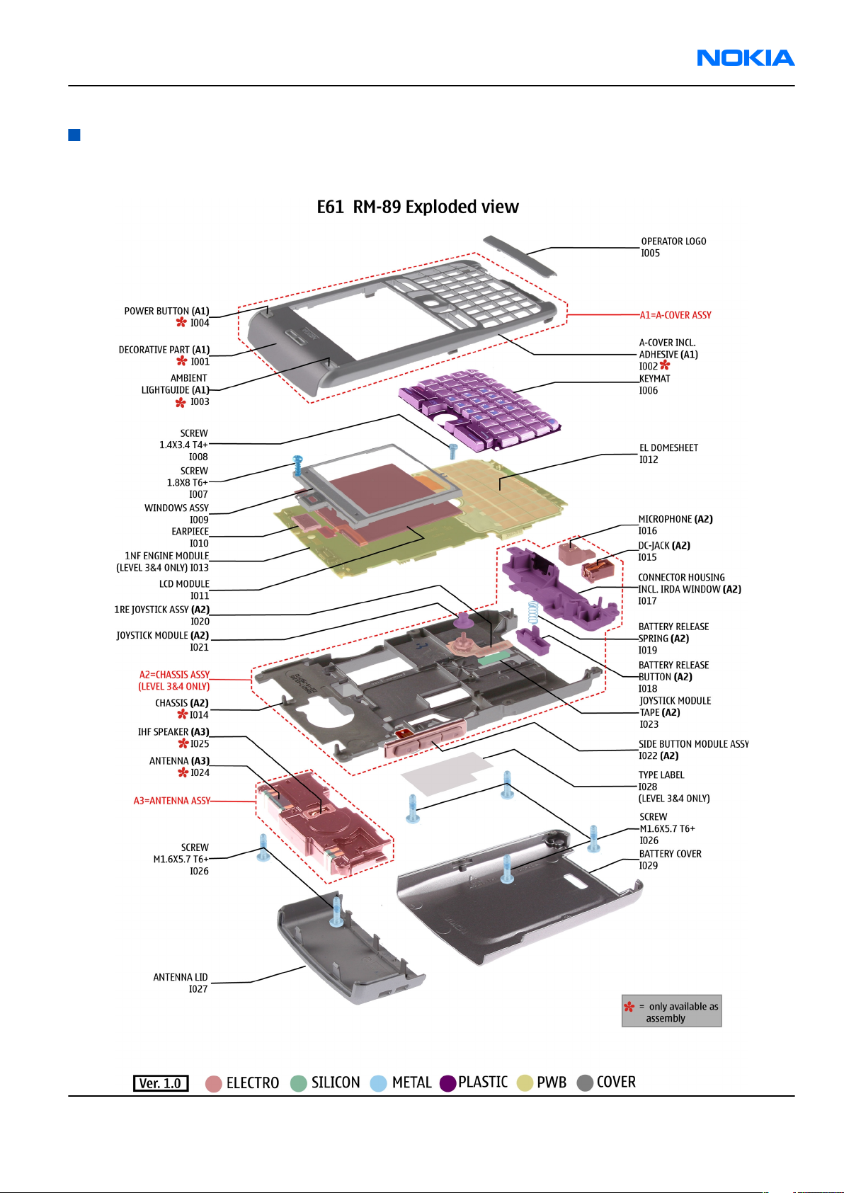
Exploded view
Exploded view
Issue 1 COMPANY CONFIDENTIAL Page 2 –5
Copyright © 2006 Nokia. All rights reserved.
Figure 2 Exploded view of RM-178
Page 26
RM-89
Nokia Customer Care Parts Lists and Component Layouts
Parts lists
Mechanical spare parts list
Note: For Nokia product codes, please refer to the latest Service Bulletins on the Partner Website (PWS).
To ensure you are always using the latest codes, please check the PWS on a daily basis.
Bold = ASSY
"XXXXXXX" = VARIANTS
"-" = NOT AVAILABLE
"???????" = AVAILABLE AS SPARE PART
I0xx = ITEM codes for upper or mono block
I1xx = ITEM codes for hinge block
I2xx = ITEM codes for lower block
I3xx = ITEM codes for soldered spare parts on the upper, hinge or lower block and not exchangable
ITEM/
PART NO PART NAME QTY
CIRCUIT
REF.
I009 ??????? Window Assembly 040-012649 1
A1 ??????? A-Cover Assembly Silver 040-012429 1
I026 ??????? SCREW M1.6X5.7 DMD12402 TORX SILV 6
I008 ??????? SCREW M1.4X3.4 TORX PLUS 4IP 1
I007 ??????? Remform screw 1.8x8 1
I019 ??????? Battery Release Spring 1
I028 ??????? BLANK LABEL 29mmx18mm EXP65673 1
I021 ??????? Joystick Button 040-012658 1
I018 ??????? Battery Release Button 040-012946 1
I023 ??????? Joystick module tape 040-020164 1
I005 XXXXXXX Operator Logo painted Silver
040-012438
I027 XXXXXXX Antenna Lid, painted Silver 040-012654 1
I029 ??????? Battery Cover painted 040-012428 Silver 1
1
I012 ??????? EL-Dome Sheet 040-012655 1
I006 XXXXXXX KEYMAT PRINTED SILVER 040-021863 EN-
1
NL
I020 ??????? 1RE JOYSTICK ASSEMBLY 1
A2 ??????? Chassis Assembly 040-012635 1
I017 ??????? CONNECTOR HOUSING ASSEMBLY
1
040-015883
I022 ??????? Side Button Module 040-012642 1
I011 ??????? LCD AM 320x240 COG 16MCo Oxford 1
Page 2 –6 COMPANY CONFIDENTIAL Issue 1
Copyright © 2006 Nokia. All rights reserved.
Page 27
RM-89
Parts Lists and Component Layouts Nokia Customer Care
ITEM/
PART NO PART NAME QTY
CIRCUIT
REF.
I016 ??????? MIC MOD+HOLDER TOMAHAWK -42+-3DB 1
I010 ??????? EARPIECE+SPRING 22+/-3DB 32R 7X11 1
I015 ??????? CONN CHR DIA 2.0MM COMPRESS 1
A3 ??????? ANTENNA MOD GSM/WCDMA P2524 1
RM-89 component parts list
Component parts list (1nf_11a_asmmtx)
Note: For Nokia product codes, please refer to the latest Service Bulletins on the Partner Website (PWS).
To ensure you are always using the latest codes, please check the PWS on a daily basis.
Item Side Grid reference Description and Value
A2200 Bottom D 7
A2801 Bottom C 13
SHIELD_P
WB_CAN_
WB
SHIELD_P
WB_CAN_
RAP
SHIELD
PWB CAN
WB ~ ~
SHIELD
PWB CAN
RAP ~ ~
A4801 Bottom K 10
A4802 Bottom L 7
A6001 Bottom L 4
A6302 Bottom H 6
A7503 Bottom D 16
A7506 Bottom G 16
A7507 Bottom G 13
SHIELD_0
40_017960PWB CAN
COMBO ~ ~
SHIELD_P
WB_CAN_
APE
SHIELD_P
WB_CAN_
BT
SHIELD_P
WB_CAN_
WLAN_BB
SHIELD_P
WB_CAN_
WCDMA
SHIELD_P
WB_CAN_
PA
SHIELD_P
WB_CAN_
PIHI
SHIELD
PWB CAN
APE ~ ~
SHIELD
PWB CAN
BT ~ ~
SHIELD
PWB CAN
WLAN BB ~ ~
SHIELD
PWB CAN
WCDMA ~ ~
SHIELD
PWB CAN
Pa ~ ~
SHIELD
PWB CAN
PIHI ~ ~
Issue 1 COMPANY CONFIDENTIAL Page 2 –7
Copyright © 2006 Nokia. All rights reserved.
Page 28

RM-89
Nokia Customer Care Parts Lists and Component Layouts
Item Side Grid reference Description and Value
CRYSTAL
32.768KH
CRYSTAL_F
B2200 Bottom D 8
C2000 Bottom D 4 0402C
C2001 Bottom D 4
C2005 Bottom F 3 0402C
C2006 Bottom G 3 0402C
C_135
0603C_H0
.95
Z+-20PPM
12.5PF
Chipcap
5% NP0 27p 50V
CHIPCAP
X5R 470N
K 25V
0603 470n 25V
Chipcap
X7R 10%
16V 0402 10n 16V
Chipcap
X7R 10%
16V 0402 10n 16V
32.768kH
z ~
TANT_C_6.
2X3.4_H1.
C2071 Bottom K 18
C2101 Bottom C 17 0402C
C2102 Bottom C 17 0402C
C2103 Top F 23 0402C
C2104 Top F 22 0402C
C2105 Bottom C 17 0402C
C2106 Bottom B 9 0402C
C2107 Bottom B 8 0402C
7
CHIPTCAP
150U M
10V
6X3.2X1.5 150u_10V 10V
Chipcap
5% NP0 68p 50V
Chipcap
5% NP0 68p 50V
Chipcap
5% X7R 1n0 50V
Chipcap
5% X7R 1n0 50V
Chipcap
X7R 10%
50V 0402 1n0 50V
Chipcap
X7R 10%
50V 0402 1n0 50V
Chipcap
X7R 10%
50V 0402 1n0 50V
Chipcap
X7R 10%
C2108 Bottom B 9 0402C
C2109 Bottom B 9 0402C
Page 2 –8 COMPANY CONFIDENTIAL Issue 1
Copyright © 2006 Nokia. All rights reserved.
50V 0402 1n0 50V
Chipcap
X7R 10%
50V 0402 1n0 50V
Page 29
RM-89
Parts Lists and Component Layouts Nokia Customer Care
Item Side Grid reference Description and Value
Chipcap
X7R 10%
C2110 Bottom B 9 0402C
C2201 Bottom D 7 0402C
C2205 Bottom D 9 0402C
C2211 Bottom C 8 0805C
0405_GN
C2213 Bottom D 7
M23
50V 0402 1n0 50V
CHIPCAP
X5R 1U5 K
4V 0402 1u5 4V
Chipcap
X7R 10%
50V 0402 1n0 50V
CHIPCAP
X5R 4U7 K
10V 0805 4u7 10V
CHIP
ARRAY
X5R 2X1U
K 6V3 MA
0405 2x1u 6.3V
0405_GN
C2215 Bottom D 7
C2216 Bottom E 7 0402C
C2217 Bottom C 9 0402C
C2220 Bottom C 8
C2222 Bottom C 7 0603C
C2225 Bottom C 7 0603C
M23
0405_GN
M23
CHIP
ARRAY
X5R 2X1U
K 6V3 MA
0405 2x1u 6.3V
CHIPCAP
X5R 1U5 K
4V 0402 1u5 4V
CHIPCAP
X5R 1U5 K
4V 0402 1u5 4V
CHIP
ARRAY
X5R 2X1U
K 6V3 MA
0405 2x1u 6.3V
CHIPCAP
X5R 1U K
6V3 0603 1u0 6.3V
CHIPCAP
X5R 1U K
6V3 0603 1u0 6.3V
CHIPCAP
X5R 1U K
C2226 Bottom D 7 0603C
Issue 1 COMPANY CONFIDENTIAL Page 2 –9
Copyright © 2006 Nokia. All rights reserved.
6V3 0603 1u0 6.3V
Page 30

RM-89
Nokia Customer Care Parts Lists and Component Layouts
Item Side Grid reference Description and Value
CHIP
ARRAY
X5R 2X1U
0405_GN
C2227 Bottom D 7
C2228 Bottom C 7
C2231 Bottom C 9 0805C
C2232 Bottom C 7
M23
0405_GN
M23
0405_GN
M23
K 6V3 MA
0405 2x1u 6.3V
CHIP
ARRAY
X5R 2X1U
K 6V3 MA
0405 2x1u 6.3V
CHIPCAP
X5R 10U M
6V3 0805 10U 6V3
CHIP
ARRAY
X5R 2X1U
K 6V3 MA
0405 2x1u 6.3V
C2235 Bottom C 9 0603C
C2236 Bottom D 9 0603C
C2237 Bottom D 6 0402C
C2238 Bottom E 9 0402C
C2239 Bottom E 14 0402C
C2300 Bottom C 5 0402C
C2301 Bottom C 5 0805C
CHIPCAP
X5R 2U2 K
6V3 0603 2u2 6V3
CHIPCAP
X5R 2U2 K
6V3 0603 2u2 6V3
Chipcap
X7R 10%
50V 0402 1n0 50V
Chipcap
X7R 10%
50V 0402 1n0 50V
Chipcap
X7R 10%
50V 0402 1n0 50V
Chipcap
X7R 10%
16V 0402 10n 16V
CHIPCAP
X5R 22U M
6V3 0805 22u 6V3
CHIPCAP
X5R 22U M
C2302 Bottom B 6 0805C
C2303 Bottom E 5 0603C
Page 2 –10 COMPANY CONFIDENTIAL Issue 1
Copyright © 2006 Nokia. All rights reserved.
6V3 0805 22u 6V3
CHIPCAP
X5R 1U K
6V3 0603 1u0 6.3V
Page 31

RM-89
Parts Lists and Component Layouts Nokia Customer Care
Item Side Grid reference Description and Value
Chipcap
X7R 10%
C2304 Bottom D 6 0402C
C2307 Bottom E 4 0603C
C2309 Bottom B 6 0805C
0405_GN
C2312 Bottom E 5
C2314 Bottom C 4 0805C
M23
16V 0402 10n 16V
CHIPCAP
X5R 1U K
6V3 0603 1u0 6.3V
CHIPCAP
X5R 22U M
6V3 0805 22u 6V3
CHIP
ARRAY
X5R 2X1U
K 6V3 MA
0405 2x1u 6.3V
CHIPCAP
X5R 4U7 M
25V 0805 4u7 25V
C2315 Bottom B 5 0805C
0402C_H0
C2700 Bottom C 17
C2800 Bottom B 13
C2801 Bottom E 13
C2802 Bottom E 13
C2803 Bottom E 12
.6
0402C_H0
.6
0402C_H0
.6
0402C_H0
.6
0402C_H0
.6
CHIPCAP
X5R 4U7 M
25V 0805 4u7 25V
CHIPCAP
X5R 100N
M 16V
0402 100n 16V
CHIPCAP
X5R 100N
M 16V
0402 100n 16V
CHIPCAP
X5R 100N
M 16V
0402 100n 16V
CHIPCAP
X5R 100N
M 16V
0402 100n 16V
CHIPCAP
X5R 100N
M 16V
0402 100n 16V
CHIPCAP
X5R 100N
0402C_H0
C2804 Bottom B 11
Issue 1 COMPANY CONFIDENTIAL Page 2 –11
Copyright © 2006 Nokia. All rights reserved.
.6
M 16V
0402 100n 16V
Page 32

RM-89
Nokia Customer Care Parts Lists and Component Layouts
Item Side Grid reference Description and Value
CHIPCAP
X5R 100N
C2805 Bottom C 14
C2806 Bottom C 11
C2807 Bottom B 12
C2808 Bottom B 14
0402C_H0
.6
0402C_H0
.6
0402C_H0
.6
0402C_H0
.6
M 16V
0402 100n 16V
CHIPCAP
X5R 100N
M 16V
0402 100n 16V
CHIPCAP
X5R 100N
M 16V
0402 100n 16V
CHIPCAP
X5R 100N
M 16V
0402 100n 16V
C2809 Bottom E 13
C2810 Bottom D 14
C2811 Bottom E 13
C2812 Bottom C 14
C2813 Bottom B 12
C2814 Bottom B 14
0402C_H0
.6
0402C_H0
.6
0402C_H0
.6
0402C_H0
.6
0402C_H0
.6
0402C_H0
.6
CHIPCAP
X5R 100N
M 16V
0402 100n 16V
CHIPCAP
X5R 100N
M 16V
0402 100n 16V
CHIPCAP
X5R 100N
M 16V
0402 100n 16V
CHIPCAP
X5R 100N
M 16V
0402 100n 16V
CHIPCAP
X5R 100N
M 16V
0402 100n 16V
CHIPCAP
X5R 100N
M 16V
0402 100n 16V
CHIPCAP
X5R 100N
0402C_H0
C2815 Bottom C 11
Page 2 –12 COMPANY CONFIDENTIAL Issue 1
Copyright © 2006 Nokia. All rights reserved.
.6
M 16V
0402 100n 16V
Page 33

RM-89
Parts Lists and Component Layouts Nokia Customer Care
Item Side Grid reference Description and Value
CHIPCAP
X5R 100N
C2816 Bottom D 11
C2817 Bottom B 11
C2818 Bottom B 14
C2819 Bottom B 13
0402C_H0
.6
0402C_H0
.6
0402C_H0
.6
0402C_H0
.6
M 16V
0402 100n 16V
CHIPCAP
X5R 100N
M 16V
0402 100n 16V
CHIPCAP
X5R 100N
M 16V
0402 100n 16V
CHIPCAP
X5R 100N
M 16V
0402 100n 16V
0402C_H0
C2820 Bottom B 11
C2821 Bottom D 11
C2822 Bottom E 12
C4200 Bottom C 10 0805C
C4201 Bottom C 10 0805C
C4202 Bottom B 9 0402C
.6
0402C_H0
.6
0402C_H0
.6
CHIPCAP
X5R 100N
M 16V
0402 100n 16V
CHIPCAP
X5R 100N
M 16V
0402 100n 16V
CHIPCAP
X5R 100N
M 16V
0402 100n 16V
CHIPCAP
X5R 22U M
6V3 0805 22u 6V3
CHIPCAP
X5R 22U M
6V3 0805 22u 6V3
Chipcap
X7R 10%
16V 0402 10n 16V
CHIPCAP
X5R 1U K
C4400 Bottom G 18 0603C
C4401 Bottom F 18 0603C
C4402 Bottom G 17 0402C
Issue 1 COMPANY CONFIDENTIAL Page 2 –13
Copyright © 2006 Nokia. All rights reserved.
6V3 0603 1u0 6.3V
CHIPCAP
X5R 1U K
6V3 0603 1u0 6.3V
Chipcap
5% NP0 27p 50V
Page 34
RM-89
Nokia Customer Care Parts Lists and Component Layouts
Item Side Grid reference Description and Value
Chipcap
C4403 Bottom F 17 0402C
C4404 Bottom A 5 0402C
C4405 Bottom A 5 0402C
C4406 Bottom C 3 0402C
C4409 Bottom K 1 0603C
0402C_H0
C4410 Bottom I 2
.6
5% NP0 27p 50V
Chipcap
5% NP0 68p 50V
CHIPCAP
X7R 15N K
16V 0402 15n 16V
CHIPCAP
X5R 1U K
6V3 0402 1u0 6.3V
CHIPCAP
X5R 4U7 K
6V3 0603 4u7 6.3V
CHIPCAP
X5R 100N
M 16V
0402 100n 16V
C4412 Bottom G 3 0402C
C4414 Bottom A 3 0603C
C4415 Top C 23 0402C
C4416 Bottom I 3 0402C
C4420 Top C 23 0402C
C4421 Top C 22 0402C
0402C_H0
C4800 Bottom K 9
C4801 Bottom I 10 0603C
.6
Chipcap
X7R 10%
50V 0402 1n0 50V
CHIPCAP
X5R 1U K
16V 0603 1u0 16V
Chipcap
X7R 10%
50V 0402 1n0 50V
Chipcap
5% NP0 27p 50V
Chipcap
5% NP0 27p 50V
Chipcap
5% NP0 27p 50V
CHIPCAP
X5R 100N
M 16V
0402 100n 16V
CHIPCAP
X5R 1U K
6V3 0603 1u0 6.3V
CHIPCAP
X5R 100N
0402C_H0
C4802 Bottom J 12
Page 2 –14 COMPANY CONFIDENTIAL Issue 1
Copyright © 2006 Nokia. All rights reserved.
.6
M 16V
0402 100n 16V
Page 35

RM-89
Parts Lists and Component Layouts Nokia Customer Care
Item Side Grid reference Description and Value
CHIPCAP
X5R 100N
C4803 Bottom I 11
C4804 Bottom K 9
C4805 Bottom I 9
C4806 Bottom L 11
0402C_H0
.6
0402C_H0
.6
0402C_H0
.6
0402C_H0
.6
M 16V
0402 100n 16V
CHIPCAP
X5R 100N
M 16V
0402 100n 16V
CHIPCAP
X5R 100N
M 16V
0402 100n 16V
CHIPCAP
X5R 100N
M 16V
0402 100n 16V
C4807 Bottom L 10
C4808 Bottom I 9
C4809 Bottom K 12
C4810 Bottom I 11
C4811 Bottom L 9
C4812 Bottom L 10
0402C_H0
.6
0402C_H0
.6
0402C_H0
.6
0402C_H0
.6
0402C_H0
.6
0402C_H0
.6
CHIPCAP
X5R 100N
M 16V
0402 100n 16V
CHIPCAP
X5R 100N
M 16V
0402 100n 16V
CHIPCAP
X5R 100N
M 16V
0402 100n 16V
CHIPCAP
X5R 100N
M 16V
0402 100n 16V
CHIPCAP
X5R 100N
M 16V
0402 100n 16V
CHIPCAP
X5R 100N
M 16V
0402 100n 16V
Chipcap
X7R 10%
C4813 Bottom K 12 0402C
Issue 1 COMPANY CONFIDENTIAL Page 2 –15
Copyright © 2006 Nokia. All rights reserved.
50V 0402 1n0 50V
Page 36

RM-89
Nokia Customer Care Parts Lists and Component Layouts
Item Side Grid reference Description and Value
CHIPCAP
X5R 100N
C5000 Bottom K 8
C5001 Bottom M 8
C5002 Bottom L 8
C5003 Bottom J 7
0402C_H0
.6
0402C_H0
.6
0402C_H0
.6
0402C_H0
.6
M 16V
0402 100n 16V
CHIPCAP
X5R 100N
M 16V
0402 100n 16V
CHIPCAP
X5R 100N
M 16V
0402 100n 16V
CHIPCAP
X5R 100N
M 16V
0402 100n 16V
0402C_H0
C5004 Bottom M 8
C5005 Bottom M 7
C5006 Bottom J 8 0603C
C5200 Bottom I 15 0603C
C5201 Bottom I 16 0402C
C5202 Bottom H 16 0603C
.6
0402C_H0
.6
CHIPCAP
X5R 100N
M 16V
0402 100n 16V
CHIPCAP
X5R 100N
M 16V
0402 100n 16V
CHIPCAP
X5R 1U K
6V3 0603 1u0 6.3V
CHIPCAP
X5R 1U K
6V3 0603 1u0 6.3V
Chipcap
X7R 10%
16V 0402 10n 16V
CHIPCAP
X5R 1U K
6V3 0603 1u0 6.3V
CHIPCAP
X5R 1U K
C5203 Bottom H 15 0603C
C5204 Bottom H 16 0603C
C6030 Bottom L 4 0402C
Page 2 –16 COMPANY CONFIDENTIAL Issue 1
Copyright © 2006 Nokia. All rights reserved.
6V3 0603 1u0 6.3V
CHIPCAP
X5R 1U K
6V3 0603 1u0 6.3V
Chipcap
5% NP0 100p 50V
Page 37

RM-89
Parts Lists and Component Layouts Nokia Customer Care
Item Side Grid reference Description and Value
Chipcap
C6031 Bottom K 5 0402C
C6033 Bottom M 4 0603C
C6036 Bottom K 5 0603C
C6037 Bottom L 5 0402C
C6038 Bottom M 5 0402C
C6039 Bottom L 4 0402C
5% NP0 15p 50V
CHIPCAP
X5R 4U7 K
6V3 0603 4u7 6.3V
CHIPCAP
X5R 4U7 K
6V3 0603 4u7 6.3V
CHIPCAP
X5R 1U K
6V3 0402 1u0 6.3V
CHIPCAP
X5R 1U K
6V3 0402 1u0 6.3V
CHIPCAP
X5R 100N
K 10V
0402 100n 10V
C6040 Bottom L 4 0402C
C6041 Bottom M 4 0402C
C6042 Bottom L 5 0603C
C6043 Bottom L 5 0402C
C6044 Bottom K 4 0603C
C6045 Bottom K 4 0603C
CHIPCAP
X5R 100N
K 10V
0402 100n 10V
CHIPCAP
X5R 0U47
K 6.3V
0402 0u47 6V3
CHIPCAP
X5R 1U K
6V3 0603 1u0 6.3V
CHIPCAP
X5R 0U47
K 6.3V
0402 0u47 6V3
CHIPCAP
X5R 1U K
6V3 0603 1u0 6.3V
CHIPCAP
X5R 1U K
6V3 0603 1u0 6.3V
Chipcap
C6051 Bottom K 4 0402C
C6300 Bottom I 7 0805C
Issue 1 COMPANY CONFIDENTIAL Page 2 –17
Copyright © 2006 Nokia. All rights reserved.
5% NP0 10p 50V
CHIPCAP
X5R 22U M
6V3 0805 22u 6V3
Page 38

RM-89
Nokia Customer Care Parts Lists and Component Layouts
Item Side Grid reference Description and Value
CHIPCAP
X5R 1U K
C6301 Bottom I 7 0603C
C6302 Bottom H 7 0603C
C6303 Bottom H 7 0603C
C6304 Bottom G 6 0402C
C6305 Bottom H 7 0402C
16V 0603 1u0 16V
CHIPCAP
X5R 2U2 K
6V3 0603 2u2 6V3
CHIPCAP
X5R 1U K
16V 0603 1u0 16V
CHIPCAP
X5R 100N
K 10V
0402 100n 10V
CHIPCAP
X5R 100N
K 10V
0402 100n 10V
C6307 Bottom G 6 0402C
C6308 Bottom I 5 0402C
C6309 Bottom I 4 0402C
C6310 Bottom G 4 0402C
C6311 Bottom I 4 0402C
C6312 Bottom H 4 0402C
C6313 Bottom I 4 0402C
CHIPCAP
X5R 1U K
6V3 0402 1u0 6.3V
Chipcap
X7R 10%
50V 0402 1n0 50V
Chipcap
X7R 10%
50V 0402 1n0 50V
CHIPCAP
X5R 100N
K 10V
0402 100n 10V
chipcap
x7r 47n k
10v 0402 47n 10V
CHIPCAP
X5R 1U5 K
4V 0402 1u5 4V
Chipcap
X7R 10%
50V 0402 1n0 50V
CHIPCAP
X5R 100N
K 10V
C6314 Bottom G 5 0402C
Page 2 –18 COMPANY CONFIDENTIAL Issue 1
Copyright © 2006 Nokia. All rights reserved.
0402 100n 10V
Page 39

RM-89
Parts Lists and Component Layouts Nokia Customer Care
Item Side Grid reference Description and Value
CHIPCAP
X5R 100N
K 10V
C6315 Bottom I 5 0402C
C6317 Bottom G 5 0402C
C6318 Bottom I 5 0402C
C6319 Bottom G 5 0402C
C6320 Bottom I 6 0402C
0402 100n 10V
CHIPCAP
X5R 100N
K 10V
0402 100n 10V
Chipcap
X7R 10%
50V 0402 1n0 50V
Chipcap
X7R 10%
50V 0402 1n0 50V
Chipcap
X7R 10%
50V 0402 1n0 50V
C6321 Bottom G 5 0402C
C6322 Bottom H 7 0402C
C6323 Bottom I 7 0402C
C6324 Bottom G 6 0402C
C6325 Bottom I 6 0402C
C6326 Bottom G 6 0402C
C6327 Bottom I 7 0402C
Chipcap
X7R 10%
50V 0402 1n0 50V
Chipcap
X7R 10%
50V 0402 1n0 50V
Chipcap
X7R 10%
50V 0402 1n0 50V
Chipcap
X7R 10%
50V 0402 1n0 50V
Chipcap
X7R 10%
50V 0402 1n0 50V
Chipcap
X7R 10%
50V 0402 1n0 50V
CHIPCAP
X5R 100N
K 10V
0402 100n 10V
Chipcap
+-0.25pF
C6328 Bottom I 1 0402C
C6330 Bottom L 3 0603C
Issue 1 COMPANY CONFIDENTIAL Page 2 –19
Copyright © 2006 Nokia. All rights reserved.
NP0 1p5 50V
CHIPCAP
X5R 4U7 K
6V3 0603 4u7 6.3V
Page 40

RM-89
Nokia Customer Care Parts Lists and Component Layouts
Item Side Grid reference Description and Value
CHIPCAP
NP0 220P
J 25V
C6335 Bottom J 4 0402C
C6338 Bottom L 3 0402C
C6340 Bottom L 3 0402C
C6344 Bottom I 4 0402C
C6345 Bottom H 4 0402C
C6346 Bottom I 6 0402C
0402 220p 25V
Chipcap
5% NP0 47p 50V
Chipcap
+-0.25pF
NP0 6p8 50V
Chipcap
+-0.25pF
NP0 6p8 50V
Chipcap
+-0.25pF
NP0 6p8 50V
Chipcap
X7R 10%
50V 0402 1n0 50V
C6347 Bottom I 6 0402C
C6348 Bottom I 5 0402C
C6351 Bottom I 7 0402C
C6352 Bottom I 5 0402C
C6360 Bottom H 4 0402C
C6361 Bottom I 4 0402C
C6364 Bottom J 4 0402C
C6365 Bottom J 4 0402C
Chipcap
5% NP0 82p 50V
CHIPCAP
X5R 1U K
6V3 0402 1u0 6.3V
Chipcap
X7R 10%
50V 0402 1n0 50V
Chipcap
5% NP0 150p 50V
CHIPCAP
NP0 220P
J 25V
0402 220p 25V
Chipcap
5% X7R 220p 50V
Chipcap
+-0.25pF
NP0 6p8 50V
Chipcap
+-0.25pF
NP0 6p8 50V
Chipcap
+-0.25pF
C6366 Bottom J 4 0402C
Page 2 –20 COMPANY CONFIDENTIAL Issue 1
Copyright © 2006 Nokia. All rights reserved.
NP0 6p8 50V
Page 41

RM-89
Parts Lists and Component Layouts Nokia Customer Care
Item Side Grid reference Description and Value
Chipcap
+-0.25pF
C6367 Bottom J 4 0402C
C6410 Bottom J 5 0402C
C7500 Bottom F 13 0603C
C7501 Bottom G 12 0603C
C7502 Bottom H 12 0603C
C7503 Bottom F 14 0603C
NP0 6p8 50V
Chipcap
X7R 10%
50V 0402 1n0 50V
CHIPCAP
X5R 4U7 K
6V3 0603 4u7 6.3V
CHIPCAP
X5R 4U7 K
6V3 0603 4u7 6.3V
CHIPCAP
X5R 4U7 K
6V3 0603 4u7 6.3V
CHIPCAP
X5R 4U7 K
6V3 0603 4u7 6.3V
C7504 Bottom G 11 0402C
C7505 Bottom G 12 0402C
C7506 Bottom F 12 0402C
0402C_H0
C7507 Bottom F 14
C7508 Bottom F 12 0402C
C7509 Bottom F 12
C7510 Bottom G 11 0402C
.6
0402C_H0
.6
Chipcap
5% X7R 3n9 50V
Chipcap
X7R 10%
16V 0402 10n 16V
Chipcap
5% NP0 27p 50V
CHIPCAP
X5R 100N
M 16V
0402 100n 16V
Chipcap
5% NP0 10p 50V
CHIPCAP
X5R 100N
M 16V
0402 100n 16V
CHIPCAP
NP0 470P
J 6V3
0402 470p 6V3
CHIPCAP
X7R 33N K
C7511 Bottom F 12 0402C
Issue 1 COMPANY CONFIDENTIAL Page 2 –21
Copyright © 2006 Nokia. All rights reserved.
10V 0402 33n 10V
Page 42

RM-89
Nokia Customer Care Parts Lists and Component Layouts
Item Side Grid reference Description and Value
CHIPCAP
NP0 2N2 G
C7512 Bottom G 11 0603C
C7514 Bottom G 15 0402C
C7515 Bottom G 15 0402C
C7516 Bottom F 11 0402C
C7521 Bottom H 17 0603C
C7527 Bottom F 15 0402C
16V 0603 2n2 16V
Chipcap
+-0.25pF
NP0 1p2 50V
Chipcap
+-0.25pF
NP0 1p5 50V
CHIPCAP
NP0 0P5 C
50V 0402 0p5 50V
CHIPCAP
X5R 4U7 K
6V3 0603 4u7 6.3V
Chipcap
+-0.25pF
NP0 1p0 50V
C7541 Bottom E 15 0603C
C7542 Bottom E 16 0603C
C7543 Bottom D 16 0603C
C7544 Bottom E 17 0402C
C7545 Bottom E 17 0402C
C7547 Bottom H 13 0402C
C7591 Top K 22 0402C
C7593 Top J 22 0402C
CHIPCAP
X5R 4U7 K
6V3 0603 4u7 6.3V
CHIPCAP
X5R 4U7 K
6V3 0603 4u7 6.3V
CHIPCAP
X5R 4U7 K
6V3 0603 4u7 6.3V
CERCAP
X7R 22N K
16V 0402 22n 16V
Chipcap
5% NP0 10p 50V
Chipcap
+-0.25pF
NP0 1p8 50V
Chipcap
5% NP0 100p 50V
Chipcap
+-0.25pF
NP0 8p2 50V
Chipcap
C7594 Top J 23 0402C
C7595 Top J 22 0402C
Page 2 –22 COMPANY CONFIDENTIAL Issue 1
Copyright © 2006 Nokia. All rights reserved.
5% NP0 12p 50V
Chipcap
5% NP0 12p 50V
Page 43
RM-89
Parts Lists and Component Layouts Nokia Customer Care
Item Side Grid reference Description and Value
Chipcap
+-0.25pF
C7597 Top J 23 0402C
D2800 Bottom C 13 VFBGA343
FBGA128_
D2801 Bottom C 13
D4800 Bottom K 10 uBGA_289
EMPTY
NP0 1p2 50V
RAP3GS
V2.0E-PA
VFBGA ~ ~
COMBO
128M NOR
+128M
DDR DRAM
FBGA128
HELEN3
PS2.0 N3
F761909
C27
UBGA289 ~ ~
8Mx16/8
Mx16 ~
D5000 Bottom L 7
D6030 Bottom J 4
F2000 Bottom C 3
G2200 Bottom E 10
G6030 Bottom K 5
COMBO
512 DDR +
1G NAND
FBGA133_
11.6X13.1
XBGA_N5_
H0.625
0603_FUS
E_AVX2MATSSM FUSE F
BATTER_E
ECEP
VCTCXO_3.
4X2.7_4P
2_H1.0
FBGA133
PBFREE
OR-GATE
2INPUT
74LVC1G3
2YZTR
WCSP-5 ~ ~
2.0A 32V 2A ~
RTC
BACUP
CAPAC
311 SIZE
FOR 2.6V
4UAH 2.6V ~
TCXO
38.4MHZ
+-10PPM
2.78V 38.4MHz ~
32Mx16/1
28Mx8 ~
VCTCXO
NKG3176
G7500 Bottom H 12
Issue 1 COMPANY CONFIDENTIAL Page 2 –23
Copyright © 2006 Nokia. All rights reserved.
B_H1.0
38.4MHZ
2.5V 2MA 38.4MHz ~
Page 44
RM-89
Nokia Customer Care Parts Lists and Component Layouts
Item Side Grid reference Description and Value
VCO
3296-398
0MHZ 4BAND
VCO_DCS0
G7501 Bottom F 12
L2000 Bottom C 4 0603_BLM
L2001 Bottom G 3
L2002 Bottom G 2
2733
0405_2_M
ATSU
0405_2_M
ATSU
MATSUSHITA3296-398
0MHz ~
FERR.BEA
D 220R/
100M 2A
0R05
0603
CHIP BEAD
ARRAY
2X1000R
0405
CHIP BEAD
ARRAY
2X1000R
0405
220R/
100MHz ~
2x1000R/
100MHz ~
2x1000R/
100MHz ~
0405_2_M
L2003 Bottom G 3
L2100 Top F 22
L2101 Bottom C 9 0603_BLM
L2102 Bottom I 21
L2103 Bottom I 21
ATSU
0405_2_M
ATSU
COIL_060
3CS
COIL_060
3CS
CHIP BEAD
ARRAY
2X1000R
0405
CHIP BEAD
ARRAY
2X1000R
0405
FERR.BEA
D 220R/
100M 2A
0R05
0603
CHIP COIL
56N J
Q38/250
MHZ 0603 56nH ~
CHIP COIL
56N J
Q38/250
MHZ 0603 56nH ~
2x1000R/
100MHz ~
2x1000R/
100MHz ~
220R/
100MHz ~
FERR.BEA
D 220R/
100M 2A
0R05
L2104 Bottom C 8 0603_BLM
Page 2 –24 COMPANY CONFIDENTIAL Issue 1
Copyright © 2006 Nokia. All rights reserved.
0603
220R/
100MHz ~
Page 45

RM-89
Parts Lists and Component Layouts Nokia Customer Care
Item Side Grid reference Description and Value
FERRITE
BEAD
220R
L2105 Bottom B 9 0402L_XL
L2106 Bottom B 9 0402L_XL
L2202 Bottom C 7 0603_BLM
L2205 Bottom C 9 0603_BLM
0R45 0.3A
0402
FERRITE
BEAD
220R
0R45 0.3A
0402
FERR.BEA
D 220R/
100M 2A
0R05
0603
FERR.BEA
D 220R/
100M 2A
0R05
0603
220R/
100MHz ~
220R/
100MHz ~
220R/
100MHz ~
220R/
100MHz ~
L2301 Bottom C 5 0603_BLM
CHOKE_SE
L2302 Bottom C 6
L2304 Bottom C 5
L4200 Bottom B 10
L4201 Bottom B 9 0603_BLM
R400
CHOKE_SE
R300_H1.
5
CHOKE_SE
R400
FERR.BEA
D 220R/
100M 2A
0R05
0603
CHOKE
10U 0.8A
0R24
4X4X1.8 10uH ~
CHOKE
22U M 0R7
0.35A
3.0x3.0x1
.5 22uH ~
CHOKE
10U 0.8A
0R24
4X4X1.8 10uH ~
FERR.BEA
D 220R/
100M 2A
0R05
0603
220R/
100MHz ~
220R/
100MHz ~
Issue 1 COMPANY CONFIDENTIAL Page 2 –25
Copyright © 2006 Nokia. All rights reserved.
Page 46

RM-89
Nokia Customer Care Parts Lists and Component Layouts
Item Side Grid reference Description and Value
FERRITE
BEAD 0.6R
600R/
L4400 Bottom G 18
L4401 Bottom F 18
L4402 Bottom B 3
L5200 Bottom I 15
FERRITE_0
402
FERRITE_0
402
CHOKE_EL
T3KN152C
FERRITE_0
402
100MHZ
0402
FERRITE
BEAD 0.6R
600R/
100MHZ
0402
COIL
0.47MH
50MA
3.3X3.4X1
.4MM 0.47MH ~
FERRITE
BEAD 0.6R
600R/
100MHZ
0402
600R/
100MHz ~
600R/
100MHz ~
600R/
100MHz ~
L6030 Bottom K 5 0402L
L6031 Bottom L 4 0402L
L6301 Bottom J 1 0402L
FERRITE_0
L7500 Bottom F 13
L7514 Bottom G 14 0402L
402
CHIP COIL
22N J
Q28/800
M 0402 22nH ~
CHIP COIL
2N2+-0N3
Q30/800
M 0402 2n2H ~
CHIP COIL
1N2
+-0N3
Q34/800
M 0402 1n2H ~
FERRITE
BEAD 0.6R
600R/
100MHZ
0402
CHIP COIL
3N3
+-0N3
Q28/800
M 0402 3n3H ~
600R/
100MHz ~
Page 2 –26 COMPANY CONFIDENTIAL Issue 1
Copyright © 2006 Nokia. All rights reserved.
Page 47

RM-89
Parts Lists and Component Layouts Nokia Customer Care
Item Side Grid reference Description and Value
CHIP COIL
3N9
+-0N3
Q28/800
L7515 Bottom G 14 0402L
FERRITE_F
L7520 Bottom H 16
L7527 Bottom F 16 0402L
L7540 Bottom D 15
BMJ1608
CHOKE_SE
R300_H1.
5
M 0402 3n9H ~
FERRITE
BEAD
0R01
28R/
100MHZ
0603
CHIP COIL
3N3
+-0N3
Q28/800
M 0402 3n3H ~
CHOKE
3U3 1.2A
0R096
3X3X1.5 3u3H ~
28R/
100MHz ~
L7541 Bottom E 17 0402L
L7543 Bottom H 13 0402L
L7591 Top J 22 0402L
VIBRA_M_
KHN4NX1
M2100 Bottom B 7
N2200 Bottom D 8
RA
TFBGA_10
5
CHIP COIL
22N J
Q28/800
M 0402 22nH ~
CHIP COIL
3N3
+-0N3
Q28/800
M 0402 3n3H ~
CHIP COIL
6N8 J
Q27/800
M 0402 6n8H ~
SMD
VIBRA
MOTOR
1.3V
80MA
9000RPM ~ ~
BASEBAN
D MODULE
VILMA
1.04C
TFBGA105 ~ ~
Issue 1 COMPANY CONFIDENTIAL Page 2 –27
Copyright © 2006 Nokia. All rights reserved.
Page 48

RM-89
Nokia Customer Care Parts Lists and Component Layouts
Item Side Grid reference Description and Value
BETTY
TFBGA64_
N2300 Bottom D 5
N2301 Bottom C 5
N4200 Bottom C 10
N4402 Bottom A 4 MSOP_10
H1.2
USMD8_1.
69X1.69
USMD_10_
2.458X1.8
99
V2.1 LF
TFBGA64 ~ ~
WHITE
LED
DRIVER
4LEDS
500MW
8BUMP
USMD8 ~ ~
DC/DC
CONV
LM3661-1
.40V/
1.05V
NOPB ~ ~
EL DRIVER
D381B
2-7V
MSOP-10 ~ ~
N4403 Bottom I 14 SC70_5
N4404 Bottom B 3 SOT_666
USMD16_
N5200 Bottom I 16
N5201 Bottom I 15
N6030 Bottom L 5
2.03X2.03
USMD16_
2.03X2.03
uBGA63_4
.6X4.6 BRF6150 ~ ~
1XOP AMP
2.7-5.5V
LMV321
SC70-5 ~ ~
TRX2+RX4
PEMD9
N&P 10K/
47K 0W12
SOT666 ~ ~
VREG &
LEVEL
SHIFT
LP3928
USMD16 ~ 2.8V
VREG &
LEVEL
SHIFT
LP3928
USMD16 ~ 2.8V
LI VREG
TK63128B
FC_4_0.99
N6031 Bottom K 4
Page 2 –28 COMPANY CONFIDENTIAL Issue 1
Copyright © 2006 Nokia. All rights reserved.
X0.99
2.8V
WLCSP4 ~ 2.8V
Page 49

RM-89
Parts Lists and Component Layouts Nokia Customer Care
Item Side Grid reference Description and Value
WLAN
MCM
STLC4370
F3 LINEAR
LFBGA_22
N6300 Bottom H 5
N6301 Bottom K 3 RF5924
N6302 Bottom K 3 SOT_666
N7500 Bottom G 13
8
TFBGA_18
8
EM
LFBGA228 ~ ~
WLAN
RF5924
ES3.5 ~ ~
TRX2+RX4
PEMD9
N&P 10K/
47K 0W12
SOT666 ~ ~
RF SYSTEM
MODULE
PIHI2.22
9.0X9.0X1 ~ ~
N7520 Bottom G 16
N7540 Bottom E 16
N7541 Bottom E 15
N7590 Top J 22
RF9282E3
.6
RF9372_H
1.5
uBGA8_1.
849X1.69
6
SC70_6_F
AIR
PA
RF9282E6
.3 GSM/
EDGE
850/900/
1800/190
0 ~ ~
PA
MODULE
RF9372E5
.2 WCDMA
1850-198
0MHZ ~ ~
DC CONV
LM3202TL
X NOPB
REVB
USMD8 ~ ~
HIGH
POWER
SPDT RF
SW SC70 ~ ~
CHIPRES
0W06 10K
R1500 Bottom L 12 0402R
R2000 Bottom G 3 0402R
Issue 1 COMPANY CONFIDENTIAL Page 2 –29
Copyright © 2006 Nokia. All rights reserved.
F 0402 10k ~
Resistor
5%
63mW 10R ~
Page 50

RM-89
Nokia Customer Care Parts Lists and Component Layouts
Item Side Grid reference Description and Value
Resistor
5%
R2001 Bottom F 3 0402R
R2002 Bottom G 2 0402_VAR
R2003 Bottom F 2 0402_VAR
R2004 Bottom E 4 0402R
63mW 10R ~
CHIP
VARISTOR
VWM5.6V
VC15.5
0402
CHIP
VARISTOR
VWM5.6V
VC15.5
0402
Resistor
5%
63mW 100R ~
5.6V/15V/
0.05J ~
5.6V/15V/
0.05J ~
R2006 Bottom G 3 BGA11
uBGA11_1
R2007 Bottom F 2
R2010 Bottom F 2 0402R
R2015 Bottom D 4
R2070 Bottom J 18 0402_VAR
R2071 Bottom C 7
.6X2.15
BGA4_1.0
1X1.07
0402_NTH
5
ASIP 4
LINES
AUDIO
FILTER
BGA11 ~ ~
ASIP SILIC
USB OTG /
ESD
BGA11 ~ ~
Resistor
5%
63mW 220k ~
ASIP TVS
BGA4 ~ ~
CHIP
VARISTOR
VWM14V
VC50V
0402 14V/50V ~
NTC RES
47K J
B=4050
+-3%
0402 47k ~
CHIP
VARISTOR
VWM14V
VC50V
R2104 Top F 22 0402_VAR
Page 2 –30 COMPANY CONFIDENTIAL Issue 1
Copyright © 2006 Nokia. All rights reserved.
0402 14V/50V ~
Page 51
RM-89
Parts Lists and Component Layouts Nokia Customer Care
Item Side Grid reference Description and Value
CHIP
VARISTOR
VWM14V
VC50V
R2105 Top F 23 0402_VAR
R2106 Bottom C 17 0402_VAR
R2107 Bottom C 17 0402_VAR
R2201 Bottom D 9 0402R
0402 14V/50V ~
CHIP
VARISTOR
VWM14V
VC50V
0402 14V/50V ~
CHIP
VARISTOR
VWM14V
VC50V
0402 14V/50V ~
Chipres
0W06
jumper
0402 0R ~
R2302 Bottom D 5 0402R
R2303 Bottom C 5 0402R
R2800 Bottom B 13 0402R
R2801 Bottom C 11 0402R
R2802 Bottom B 12 0402R
R2803 Bottom B 13 0402R
R4400 Top C 22 0402R
Resistor
5%
63mW 100R ~
Resistor
5%
63mW 33R ~
Resistor
5%
63mW 10R ~
Resistor
5%
63mW 4k7 ~
Resistor
5%
63mW 4k7 ~
Resistor
5%
63mW 4k7 ~
Resistor
5%
63mW 470k ~
Resistor
5%
R4401 Top B 22 0402R
Issue 1 COMPANY CONFIDENTIAL Page 2 –31
Copyright © 2006 Nokia. All rights reserved.
63mW 100k ~
Page 52

RM-89
Nokia Customer Care Parts Lists and Component Layouts
Item Side Grid reference Description and Value
Resistor
5%
R4402 Top C 22 0402R
0402_NTH
R4403 Top C 22
R4404 Bottom A 3 0402R
R4406 Top L 22 0402_VAR
5
63mW 470k ~
NTC RES
47K J
B=4050
+-3%
0402 47k ~
Chipres
0W06
jumper
0402 0R ~
CHIP
VARISTOR
VWM14V
VC50V
0402 14V/50V ~
R4407 Bottom H 13 0402R
R4408 Bottom C 3 0402R
R4409 Bottom H 14 0402R
R4410 Bottom H 15 0402R
R4411 Bottom B 5 0402R
R4412 Top B 22 0402R
R4413 Top C 22 0402R
Resistor
5%
63mW 18R ~
Chipres
0W06 5%
0402 3M3 ~
Resistor
5%
63mW 33R ~
Resistor
5%
63mW 1k0 ~
Resistor
5%
63mW 82k ~
Resistor
5%
63mW 680R ~
Resistor
5%
63mW 1k0 ~
Resistor
5%
R4414 Bottom B 2 0402R
0805R_TH
R4423 Bottom K 1
Page 2 –32 COMPANY CONFIDENTIAL Issue 1
Copyright © 2006 Nokia. All rights reserved.
ERM1
63mW 100k ~
CHIPRES
0W125
4R7 J
0805 4R7 ~
Page 53

RM-89
Parts Lists and Component Layouts Nokia Customer Care
Item Side Grid reference Description and Value
Resistor
5%
R4429 Bottom G 3 0402R
R4506 Bottom B 17 0402R
R4507 Bottom B 17 0402R
R4508 Bottom B 17 0402R
R4509 Bottom B 16 0402R
63mW 100k ~
Chipres
0W06
jumper
0402 0R ~
Chipres
0W06
jumper
0402 0R ~
Chipres
0W06
jumper
0402 0R ~
Chipres
0W06
jumper
0402 0R ~
R4800 Bottom K 9 0402R
R4801 Bottom I 8 0402R
R4802 Bottom I 8 0402R
R4809 Bottom I 11 0402R
R5200 Bottom H 16 0402R
R5201 Bottom H 17 0402R
R5202 Bottom I 15 0402R
Resistor
5%
63mW 10R ~
Resistor
5%
63mW 47R ~
Resistor
5%
63mW 47R ~
Resistor
5%
63mW 1k0 ~
Resistor
5%
63mW 680R ~
Resistor
5%
63mW 1k2 ~
Resistor
5%
63mW 100k ~
Resistor
5%
R6054 Bottom L 5 0402R
Issue 1 COMPANY CONFIDENTIAL Page 2 –33
Copyright © 2006 Nokia. All rights reserved.
63mW 100k ~
Page 54

RM-89
Nokia Customer Care Parts Lists and Component Layouts
Item Side Grid reference Description and Value
Resistor
5%
R6055 Bottom J 5 0402R
R6065 Bottom M 5 0402R
R6300 Bottom G 6 0402R
R6301 Bottom I 6 0402R
R6304 Bottom G 5 0402R
63mW 100k ~
Resistor
5%
63mW 10k ~
CHIPRES
0W06 1M
F 100PPM
0402 1M0 ~
Resistor
5%
63mW 1k2 ~
Chipres
0W06
jumper
0402 0R ~
R6354 Bottom I 4 0402R
R6424 Bottom J 5 0402R
R7500 Bottom G 12 0402R
R7501 Bottom F 14 0402R
R7503 Bottom G 12 0402R
R7504 Bottom G 12 0402R
R7509 Bottom F 12 0402R
Resistor
5%
63mW 3k3 ~
Resistor
5%
63mW 100R ~
Resistor
5%
63mW 22k ~
Resistor
5%
63mW 4k7 ~
CHIPRES
0W06 1K0
F 200PPM
0402 1k0 ~
CHIPRES
0W06 8K2
F 0402 8k2 ~
Chipres
0W06 5R6
J 0402 5R6 ~
CHIPRES
0W06 27K
R7520 Bottom H 16 0402R
Page 2 –34 COMPANY CONFIDENTIAL Issue 1
Copyright © 2006 Nokia. All rights reserved.
F 0402 27k ~
Page 55

RM-89
Parts Lists and Component Layouts Nokia Customer Care
Item Side Grid reference Description and Value
Chipres
0W06 47k
F 200ppm
R7540 Bottom D 16 0402R
R7541 Bottom E 15 0402R
R7542 Bottom E 17 0402R
R7543 Bottom E 17 0402R
R7544 Bottom D 16 0402R
0402 47k ~
CHIPRES
0W06 1K2
F 250PPM
0402 1k2 ~
Chipres
0W06
jumper
0402 0R ~
Resistor
5%
63mW 10k ~
Resistor
5%
63mW 10R ~
R7549 Bottom E 18 0402R
R7590 Top J 23 0402R
R7591 Top J 22 0402R
R7593 Top K 23 0402R
BUTTON_E
S4401 Top L 22
S4402 Bottom H 3
VPAA
SWITCH_E
SE13V01C
Chipres
0W06
jumper
0402 0R ~
Chipres
0W06
jumper
0402 0R ~
Chipres
0W06
jumper
0402 0R ~
Chipres
0W06
jumper
0402 0R ~
SWITCH
PB LIGHT
EVPAA
15V 20MA ~ ~
SM SW
DETECTOR
SWITCH
5V 10MA ~ ~
TRANSF
BALUN
TRANS_LD
T6030 Bottom K 4
Issue 1 COMPANY CONFIDENTIAL Page 2 –35
Copyright © 2006 Nokia. All rights reserved.
B213
2400
+-100MHZ ~ ~
Page 56

RM-89
Nokia Customer Care Parts Lists and Component Layouts
Item Side Grid reference Description and Value
TRANSF
BALUN
2134
TRANS_LD
T7500 Bottom F 14
T7501 Bottom G 12
V2303 Bottom D 5 SOD323F
V4400 Top B 22
B15
TRANS_LD
B15
PT202MR
0MP
+-90MHZ
0805 ~ ~
TRANSF
BALUN
3800
+-550MHZ
0805 ~ ~
SCH DI
30V 2A
SOD323F ~ ~
DI PHOTO
PT202MR
0MP
620NM
1.25X2 ~ ~
V4401 Bottom C 3 SC_76
V4402 Bottom C 4 SC_76
V4403 Bottom I 14 VMT3
CIM_138M
V4404 Bottom J 2
V4405 Top B 22
7_T
LED_CL19
1
DI ZEN
100V 6%
200MW
SC-76 SSP ~ ~
DI ZEN
100V 6%
200MW
SC-76 SSP ~ ~
TR
2SC5658Q
RS N 50V
0A1 0W15
VMT3 ~ ~
IRDA
1.152
MBITS/S
WITH LIFT
PWB ~ ~
LED
CL-191WB
-D-T
WHITE 0`
115MCD
0603 ~ ~
Page 2 –36 COMPANY CONFIDENTIAL Issue 1
Copyright © 2006 Nokia. All rights reserved.
Page 57

RM-89
Parts Lists and Component Layouts Nokia Customer Care
Item Side Grid reference Description and Value
TR
2SC5658Q
RS N 50V
0A1 0W15
V4406 Top C 22 VMT3
ANT_REN
W6300 Bottom J 1
X2001 Bottom F 1
X2060 Top F 1
M05041
SYSCON_M
Q202_NK_
14R3
TRACEABI
LITY_PAD
VMT3 ~ ~
BT/WLAN
1.0 TP
ANTENNA
RELEASE ~ ~
SM
SYSTEM
CONNECT
OR 14POL ~ ~
MODULE
ID
COMPONE
NT
2.8X1.8X0
.3 ~ ~
X2070 Bottom I 18
X2100 Bottom H 21
X2101 Bottom H 21
X2700 Bottom C 15
X4400 Top E 22
LYNX_BAT
T_CONN_H
7.0
CONN_AN
T_DMD11
562
CONN_AN
T_DMD11
562
SIM_CONN
_M_SK_20
0300383
JST_R_JAV
K_G_1_R3
SM
BATTERY
CONN
3POL SPR
12V 2A ~ ~
CON PPP
ANTENNA
R1024
DMD1156
2 ~ ~
CON PPP
ANTENNA
R1024
DMD1156
2 ~ ~
SM SIM
CONN
2X3POL
P2.54
H4.6 ~ ~
SM CONN
2X12F
P0.4 30V
0.3A PCB/
PCB ~ ~
Issue 1 COMPANY CONFIDENTIAL Page 2 –37
Copyright © 2006 Nokia. All rights reserved.
Page 58

RM-89
Nokia Customer Care Parts Lists and Component Layouts
Item Side Grid reference Description and Value
SM LCD
X4500 Bottom F 8
X4501 Bottom B 17
X5200 Bottom K 15
X6300 Top K 2
CONN_SD_
54742_00
2
SMK_4309
_B_B_6P_V
2
MINISD_S
C1S011V1
S3
COAX_MM
8430
CONN 1X8
P2.0 SPR
50V 0.5A ~ ~
SM CONN
6P SPR
P1.3 50V
BTOB ~ ~
CONN
MINISD
PUSHPUSH 3.3V
0.5A ~ ~
CONN SM
COAX+ SW
F 50R
250V
6GHZ ~ ~
X7500 Bottom B 23
X7501 Bottom C 23
X7504 Bottom M 23
X7505 Bottom L 23
X7507 Bottom J 23
Z2000 Bottom F 3
SPRING_W
N9149_N
10
SPRING_W
N9149_N
10
SPRING_W
N9149_N
10
SPRING_W
N9149_N
10
SPRING_W
N9149_N
10
FERRITE_0
402
C-SPRING
ANTENNA
active ~ ~
C-SPRING
ANTENNA
active ~ ~
C-SPRING
ANTENNA
active ~ ~
C-SPRING
ANTENNA
active ~ ~
C-SPRING
ANTENNA
active ~ ~
FERRITE
BEAD 0.6R
600R/
100MHZ
0402
600R/
100MHz ~
FERRITE
BEAD 0.6R
600R/
FERRITE_0
Z2001 Bottom F 3
Page 2 –38 COMPANY CONFIDENTIAL Issue 1
Copyright © 2006 Nokia. All rights reserved.
402
100MHZ
0402
600R/
100MHz ~
Page 59

RM-89
Parts Lists and Component Layouts Nokia Customer Care
Item Side Grid reference Description and Value
FERRITE
BEAD 0.6R
600R/
Z2003 Bottom F 3
Z4402 Bottom F 18
Z4403 Bottom G 18
Z4500 Bottom M 11
FERRITE_0
402
uBGA25_2
.47X2.47
uBGA25_2
.47X2.47
uBGA25_2
.47X2.47
100MHZ
0402
ASIP 10CH ESD
EMI
FILTER
BGA25 ~ ~
ASIP 10CH ESD
EMI
FILTER
BGA25 ~ ~
ASIP 10CH ESD
EMI
FILTER
BGA25 ~ ~
600R/
100MHz ~
Z4501 Bottom M 12
Z4502 Bottom I 13
Z5200 Bottom I 17
Z6300 Bottom L 4
Z7500 Bottom G 15
uBGA25_2
.47X2.47
uBGA25_2
.47X2.47
FLIP_CHIP
_16_2.01X
2.02_H0.7
15
FILTER_LF
B322G
MODULE_S
P_LMZ_13
7
ASIP 10CH ESD
EMI
FILTER
BGA25 ~ ~
ASIP 10CH ESD
EMI
FILTER
BGA25 ~ ~
MMC ASP
HIGH
SPEED
BGA16 ~ ~
CER FILT
2450
+-50MHZ
3.2X2.5 2450MHz ~
TX SAW
MODULE
GSM
850/900
MHZ
850/900
MHz ~
Issue 1 COMPANY CONFIDENTIAL Page 2 –39
Copyright © 2006 Nokia. All rights reserved.
Page 60

RM-89
Nokia Customer Care Parts Lists and Component Layouts
Item Side Grid reference Description and Value
CER FILT
LFL18169
9TC1
Z7520 Bottom F 16
Z7540 Bottom D 17
FILTER_LF
TC10N
P_TC3N_1
2_1_AGI
2400-248
0MHZ 1.6
DUPL BAW
1920-198
0/2110-2
170MHZ
3.8X3.8
2400-248
3MHz ~
1920-198
0/2110-2
170MHZ ~
Page 2 –40 COMPANY CONFIDENTIAL Issue 1
Copyright © 2006 Nokia. All rights reserved.
Page 61

RM-89
Parts Lists and Component Layouts Nokia Customer Care
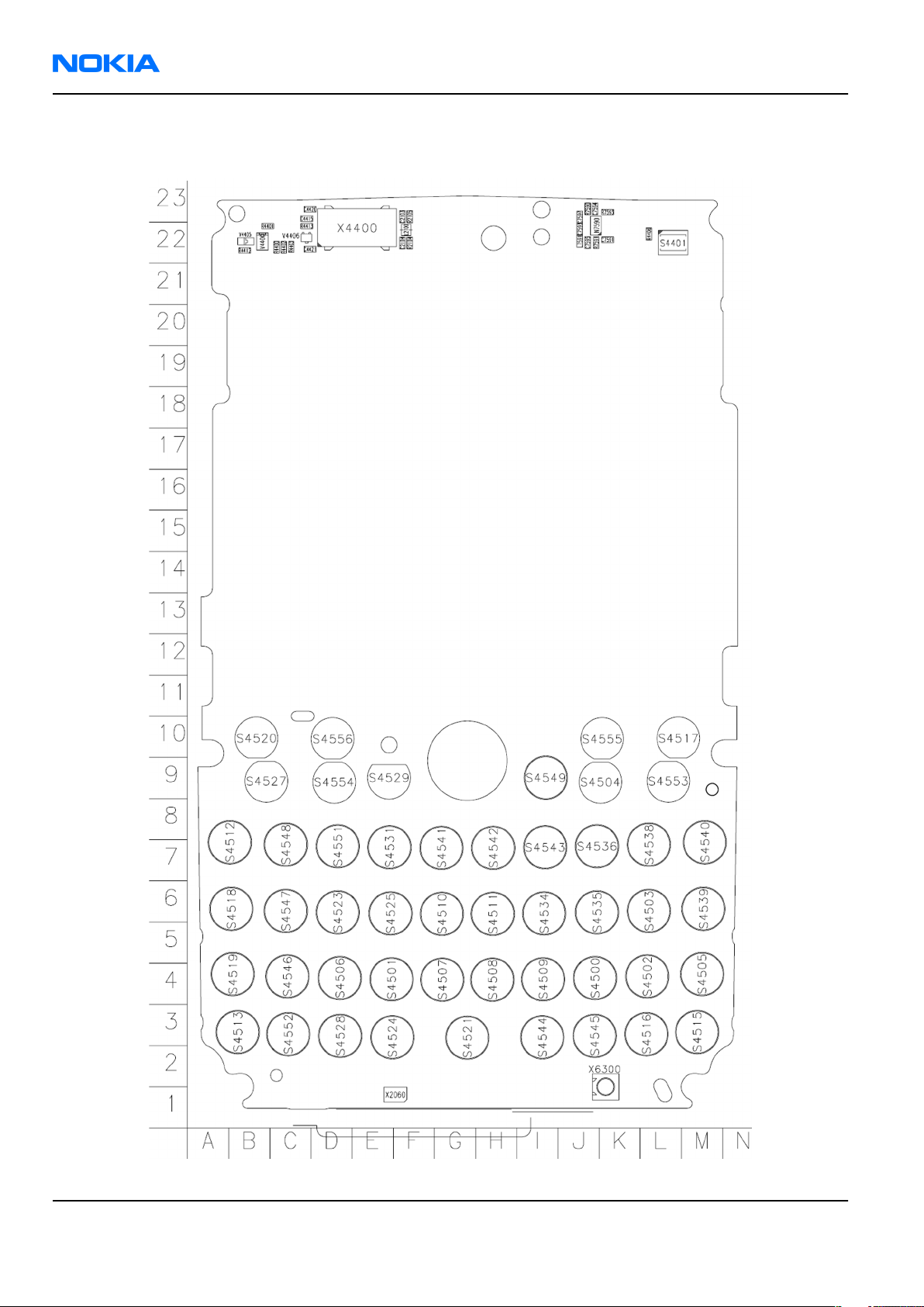
Component layouts
Component layout - bottom (1nf_11a_asmdrw)
Issue 1 COMPANY CONFIDENTIAL Page 2 –41
Copyright © 2006 Nokia. All rights reserved.
Page 62
RM-89
Nokia Customer Care Parts Lists and Component Layouts
Component layout - top (1nf_11a_asmdrw)
Page 2 –42 COMPANY CONFIDENTIAL Issue 1
Copyright © 2006 Nokia. All rights reserved.
Page 63

Nokia Customer Care
3 — Service Software
Instructions
Issue 1 COMPANY CONFIDENTIAL Page 3 –1
Copyright © 2006 Nokia. All rights reserved.
Page 64

RM-89
Nokia Customer Care Service Software Instructions
(This page left intentionally blank.)
Page 3 –2 COMPANY CONFIDENTIAL Issue 1
Copyright © 2006 Nokia. All rights reserved.
Page 65

RM-89
Service Software Instructions Nokia Customer Care
Table of Contents
Phoenix installation steps in brief........................................................................................................................3–5
Installing Phoenix...................................................................................................................................................3–6
Updating Phoenix installation..............................................................................................................................3–8
Uninstalling Phoenix..............................................................................................................................................3–9
Phone data package overview............................................................................................................................3–11
Installing phone data package...........................................................................................................................3–11
Uninstalling phone data package.......................................................................................................................3–14
Configuring users in Phoenix..............................................................................................................................3–16
Managing connections in Phoenix......................................................................................................................3–16
Installing flash support files for FPS-10.............................................................................................................3–18
Updating FPS-10 flash prommer software........................................................................................................3–21
List of Figures
Figure 3 Dongle not found.....................................................................................................................................3–6
Figure 4 Disclaimer text.........................................................................................................................................3–7
Figure 5 InstallShield Wizard Complete...............................................................................................................3–8
Figure 6 Installation interrupted..........................................................................................................................3–9
Figure 7 Remove program...................................................................................................................................3–10
Figure 8 Finish uninstallation.............................................................................................................................3–10
Figure 9 Data package setup information.........................................................................................................3–12
Figure 10 Data package destination folder.......................................................................................................3–13
Figure 11 InstallShield Wizard Complete...........................................................................................................3–14
Figure 12 Uninstalling phone data package......................................................................................................3–15
Figure 13 Finishing data package uninstallation..............................................................................................3–15
Figure 14 Phoenix login.......................................................................................................................................3–16
Figure 15 New user configured..........................................................................................................................3–16
Figure 16 Select mode: Manual...........................................................................................................................3–17
Figure 17 Connections list...................................................................................................................................3–18
Figure 18 Connection information.....................................................................................................................3–18
Figure 19 Product support module information (example from RM-1)..........................................................3–18
Figure 20 Flash update welcome dialog............................................................................................................3–19
Figure 21 Flash installation interrupted............................................................................................................3–19
Figure 22 Flash destination folder......................................................................................................................3–20
Figure 23 Finish flash update..............................................................................................................................3–21
Figure 24 Flash directory window......................................................................................................................3–21
Figure 25 Prommer software update finished..................................................................................................3–22
Figure 26 Prommer Maintenance window........................................................................................................3–22
Issue 1 COMPANY CONFIDENTIAL Page 3 –3
Copyright © 2006 Nokia. All rights reserved.
Page 66

RM-89
Nokia Customer Care Service Software Instructions
(This page left intentionally blank.)
Page 3 –4 COMPANY CONFIDENTIAL Issue 1
Copyright © 2006 Nokia. All rights reserved.
Page 67

RM-89
Service Software Instructions Nokia Customer Care
Phoenix
installation steps in brief
Prerequisites
Recommended hardware requirements:
• Computer processor: Pentium 700 MHz or higher
• RAM 256 MB
• Disk space 100-300 MB
Supported operating systems:
•
Windows 2000
•
Windows XP
Service Pack 3 or higher
Service Pack 1 or higher
Context
Phoenix
is a service software for reprogramming, testing and tuning phones.
Phoenix
• Service software support for all phone models included in the package
• Flash update package files for programming devices
• All needed drivers for:
The phone model specific data package includes all changing product specific data:
• Product software binary files
• Files for type label printing
• Validation file for the faultlog repair data reporting system
• All product specific configuration files for
To use
installation contains:
• PKD-1 (DK2) dongle
• DKU-2 or CA-53 USB cable
Note: Separate installation packages for flash update files and drivers are also available, but it is
not necessary to use them unless there are updates between
separate update packages are used, they should be used after
installed.
Note:
Uninstallation should be made from the
Phoenix
Phoenix
, you need to:
and phone data packages should only be used as complete installation packages.
Phoenix
software components
Windows
Control Panel.
Phoenix
Phoenix
service software releases. If
and data packages have been
Steps
1. Connect a PKD-1 (DK2) dongle to the computer parallel port.
2. Install
3. Install the phone-specific data package.
4. Configure users.
Issue 1 COMPANY CONFIDENTIAL Page 3 –5
Phoenix
.
Copyright © 2006 Nokia. All rights reserved.
Page 68

RM-89
Nokia Customer Care Service Software Instructions
5. Manage connection settings (depends on the tools you are using).
If you use FPS-10: • Update FPS-10 software
Note: There is no need to activate FPS-10.
• Activate SX-4 smart card, if you need tuning and
testing functions.
Note: When FPS-10 is used only for
product software updates, SX-4 smart
card is not needed.
Results
Phoenix
is ready to be used with FPS-10 flash prommer and other service tools.
Installing
Phoenix
Prerequisites
• Check that a dongle is attached to the parallel port of your computer.
• Download the
computer (in
• Close all other programs.
• Depending on your operating system, administrator rights may be required to install
• If uninstalling or rebooting is needed at any point, you will be prompted by the InstallShield program.
Phoenix
C:\TEMP
installation package (for example,
, for instance).
phoenix_service_sw_2004_39_x_xx.exe
Phoenix
) to your
.
Context
At some point during the installation procedure, you may get the following message:
Figure 3 Dongle not found
This may be a result of a defective or too old PKD-1 dongle.
Check the COM/parallel ports used. After correcting the problem, you can restart the installation.
For more detailed information, please refer to
Tip: Each feature in
program. Press the F1 key or the feature’s Help button to activate a Help file.
Phoenix
has its own Help function, which can be activated while running the
Phoenix
Help files.
Steps
1. To start the installation, run the application file (for example,
2. In the
Page 3 –6 COMPANY CONFIDENTIAL Issue 1
Welcome
dialogue, click Next.
Copyright © 2006 Nokia. All rights reserved.
phoenix_service_sw_2004_39_x_xx.exe
).
Page 69

RM-89
Service Software Instructions Nokia Customer Care
3. Read the disclaimer text carefully and click Yes.
Figure 4 Disclaimer text
4. Choose the destination folder.
The default folder
C:\ProgramFiles\Nokia\Phoenix
is recommended.
5. To continue, click Next.
To choose another location, click Browse (not recommended).
6. Wait for the components to be copied.
The progress of the installation is shown in the
Setup Status
window.
7. Wait for the drivers to be installed and updated.
The process may take several minutes to complete.
If the operating system does not require rebooting, the PC components are registered right away.
If the operating system requires restarting your computer, the Install Shield Wizard will notifies about it.
Select Yes... to reboot the PC immediately or No... to reboot the PC manually afterwards.
After the reboot, all components are registered.
Note:
Phoenix
does not work, if the components have not been registered.
Issue 1 COMPANY CONFIDENTIAL Page 3 –7
Copyright © 2006 Nokia. All rights reserved.
Page 70
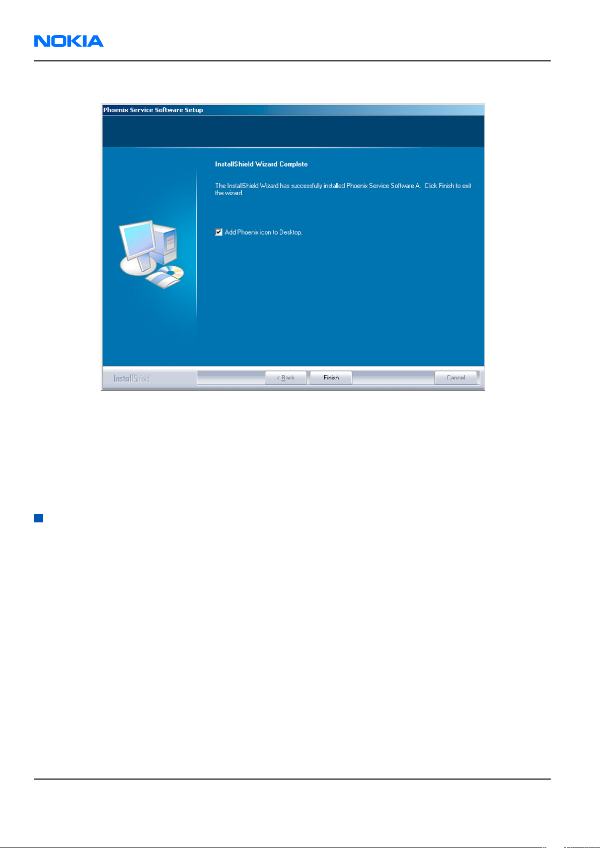
RM-89
Nokia Customer Care Service Software Instructions
8. To end the installation, click Finish.
Figure 5 InstallShield Wizard Complete
Next actions
After the installation,
• installing phone model specific data package for
• configuring users and connections
FPS-10 flash prommer can be used after updating their flash update package files.
Updating
Phoenix
Phoenix
can be used after:
Phoenix
installation
Context
• If you already have the
software when new versions are released.
• To update
• When you are updating, for example, from version a14_2004_16_4_47 to a15_2004_24_7_55, the update
will take place automatically without uninstallation.
• Always use the latest available versions of both
can be found in the phone model specific Technical Bulletins and phone data package
(shown during installation).
• If you try to update
to a15_2004_24_7_55), you are asked if you want to uninstall the existing version. In this case you can
choose between a total uninstallation or a repair installation in a similar way when choosing to uninstall
the application from the
Phoenix
Phoenix
, you need to follow the same steps as when installing it for the first time.
Phoenix
Windows
service software installed on your computer, you need to update the
Phoenix
with the same version you already have (for example, a15_2004_24_7_55
Control Panel.
and the phone-specific data package. Instructions
readme.txt
files
• If you try to install an older version (for example, downgrade from a15_2004_24_7_55 to
a14_2004_16_4_47), installation will be interrupted.
Page 3 –8 COMPANY CONFIDENTIAL Issue 1
Copyright © 2006 Nokia. All rights reserved.
Page 71

RM-89
Service Software Instructions Nokia Customer Care
Figure 6 Installation interrupted
• Always follow the instructions on the screen.
Steps
1. Download the installation package to your computer hard disk.
2. Close all other programs.
3. Run the application file (for example,
phoenix_service_sw_2004_39_x_xx.exe
).
Results
A new
Phoenix
version is installed and driver versions are checked and updated.
Uninstalling
Phoenix
Context
You can uninstall
Phoenix
service software manually from the
Windows
Control Panel.
Steps
1. Open the Windows Control Panel, and choose Add/Remove Programs.
Issue 1 COMPANY CONFIDENTIAL Page 3 –9
Copyright © 2006 Nokia. All rights reserved.
Page 72

RM-89
Nokia Customer Care Service Software Instructions
2. To uninstall
Phoenix
, choose Phoenix Service Software→Change/Remove→Remove .
Figure 7 Remove program
The progress of the uninstallation is shown.
3. If the operating system does not require rebooting, click Finish to complete.
Figure 8 Finish uninstallation
Page 3 –10 COMPANY CONFIDENTIAL Issue 1
Copyright © 2006 Nokia. All rights reserved.
Page 73

RM-89
Service Software Instructions Nokia Customer Care
If the operating system requires rebooting, InstallShield Wizard will notify you. Select Yes... to reboot the
PC immediately and No... to reboot the PC manually afterwards.
Phone data package overview
Each product has its own data package (DP). The product data package contains all product-specific data files
to make the Phoenix service software and tools usable with a certain phone model.
The phone data package contains the following:
• Product software binary files
• Files for type label printing
• Validation file for the fault log repair data reporting system
• All product-specific configuration files for Phoenix software components
Data files are stored in C:\Program Files\Nokia\Phoenix (default).
Installing phone data package
Prerequisites
• A phone-specific data package contains all data required for the
to be used with a certain phone model.
• Check that a dongle is attached to the parallel port of your computer.
• Install
Phoenix
service software.
Phoenix
service software and service tools
• Download the installation package (for example,
in C:\TEMP).
• Close all other programs.
(XX-XX = type designator of the product)
If you already have
released.
Note: Often
version of
available versions of both. Instructions can be found in phone-specific Technical Bulletins and
readme.txt
Phoenix
Phoenix
Phoenix
files of data packages.
installed on your computer, you will need to update it when a new version is
and the phone-specific data package come in pairs, meaning that a certain
can only be used with a certain version of a data package. Always use the latest
XX-XX_dp_EA_v_1_0.exe
Steps
1. To start the installation, run the application file (for example,
Wait for the installation files to be extracted.
) to your computer (for example,
XX-XX_dp_EA_ v_1_0.exe
),
Issue 1 COMPANY CONFIDENTIAL Page 3 –11
Copyright © 2006 Nokia. All rights reserved.
Page 74
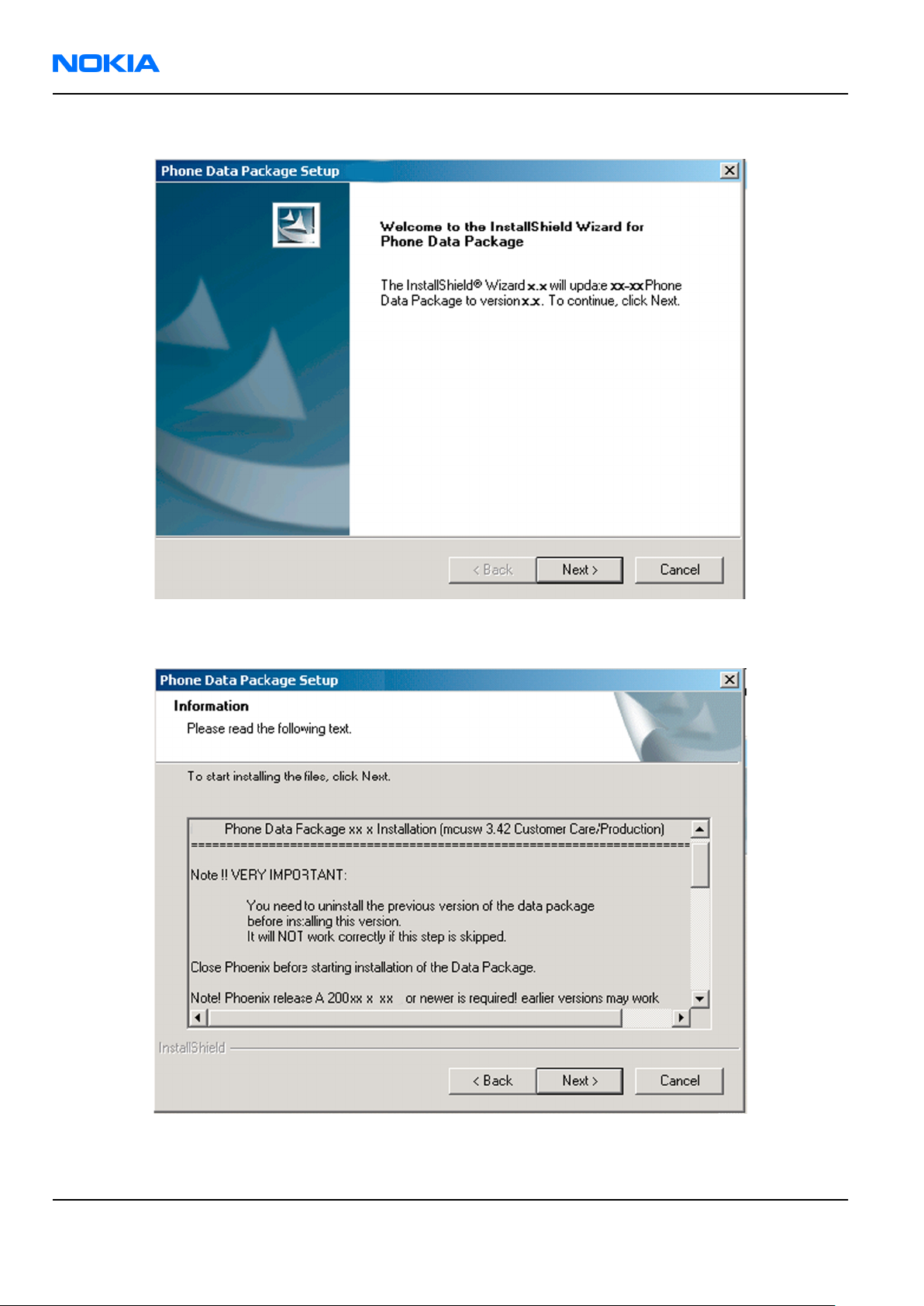
RM-89
Nokia Customer Care Service Software Instructions
2. Click Next.
3. In the following view you can see the contents of the data package. Read the text carefully. There is
information about the
Phoenix
version required with this data package.
Figure 9 Data package setup information
4. To continue, click Next.
Page 3 –12 COMPANY CONFIDENTIAL Issue 1
Copyright © 2006 Nokia. All rights reserved.
Page 75
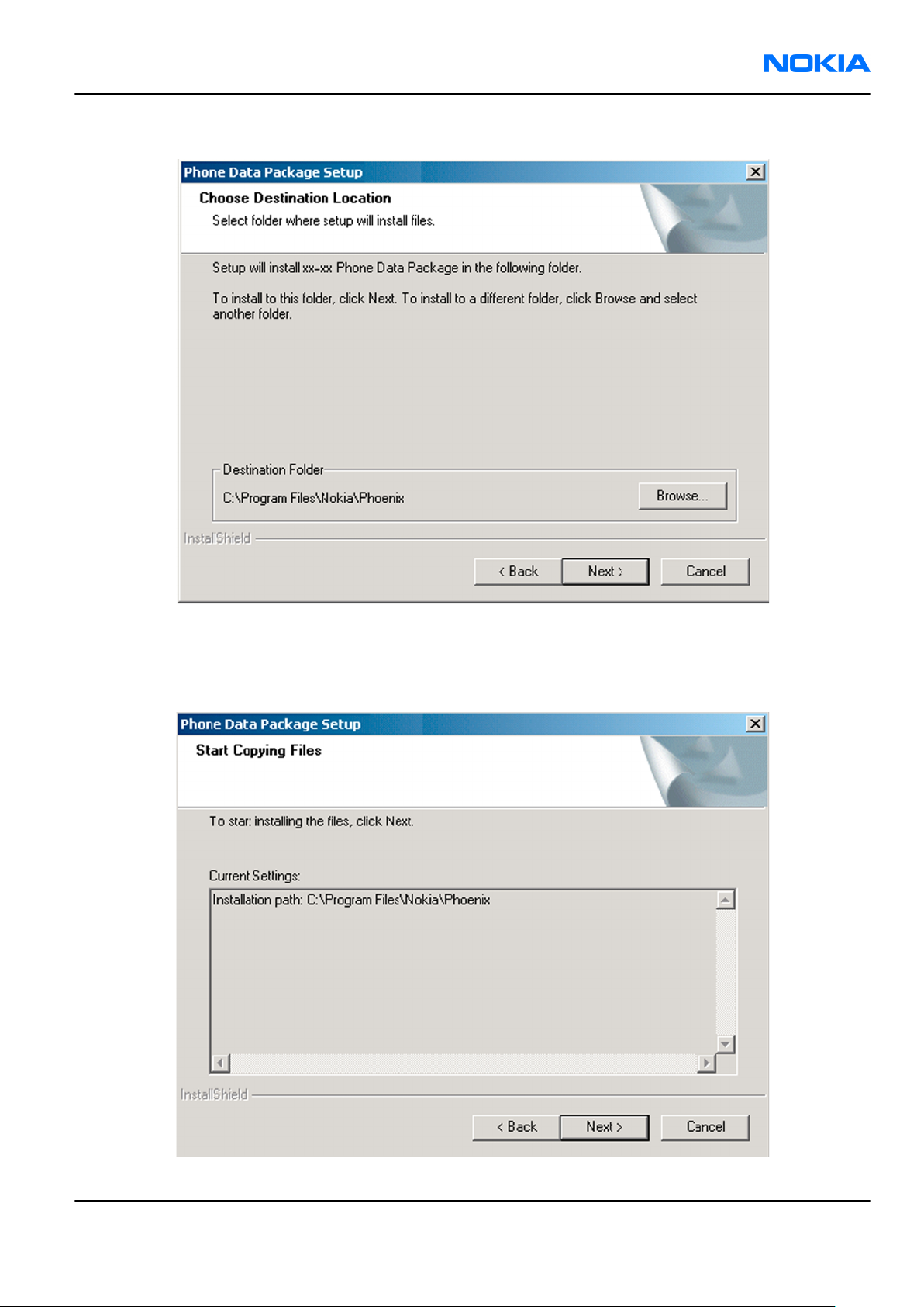
RM-89
Service Software Instructions Nokia Customer Care
5. Choose the destination folder, and click Next to continue.
Figure 10 Data package destination folder
The InstallShield Wizard checks where
6. To start copying the files, click Next.
Phoenix
is installed, and the directory is shown.
Issue 1 COMPANY CONFIDENTIAL Page 3 –13
Copyright © 2006 Nokia. All rights reserved.
Page 76
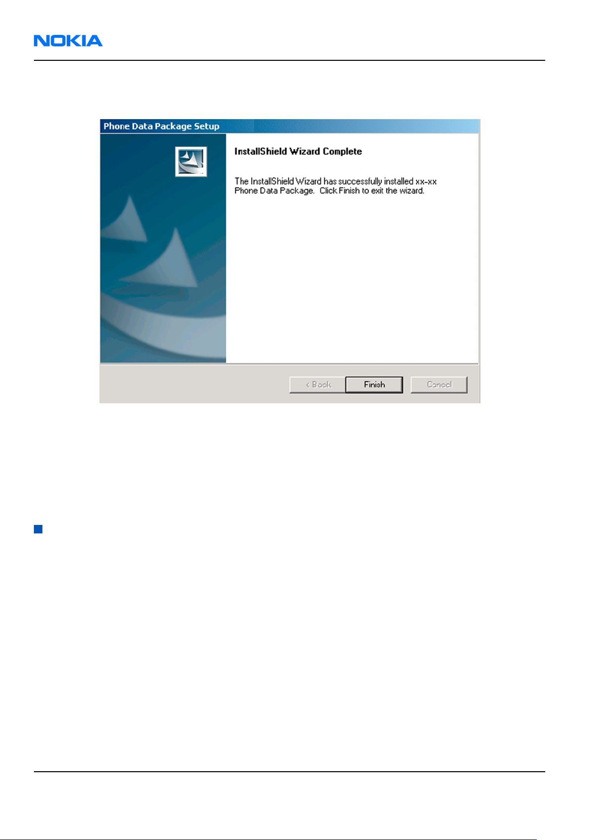
RM-89
Nokia Customer Care Service Software Instructions
Phone model specific files are installed. Please wait.
7. To complete the installation, click Finish.
Figure 11 InstallShield Wizard Complete
Next actions
Phoenix
• Configuring users
• Managing connections
FPS-10 can be used after updating its flash update package files.
can be used for flashing phones and printing type labels after:
Uninstalling phone data package
Context
There is no need to uninstall an older version of a data package, unless instructions to do so are given in
the
readme.txt
Please read all related documents carefully.
file of the data package and bulletins related to the release.
Steps
1. Locate the data package installation file (e.g.
2. To start the uninstallation procedure, double-click the data package installation file.
XX-XX_dp_EA_v_1_0.exe
) from your computer.
Page 3 –14 COMPANY CONFIDENTIAL Issue 1
Copyright © 2006 Nokia. All rights reserved.
Page 77

RM-89
Service Software Instructions Nokia Customer Care
3. To uninstall the data package, click OK or to interrupt the uninstallation, click Cancel.
Figure 12 Uninstalling phone data package
4. When the data package is uninstalled, click Finish.
Figure 13 Finishing data package uninstallation
Alternative steps
• You can also uninstall the data package manually from
Control Panel→Add/Remove Programs→xx-xx* Phone Data Package . (*= type designator of the
phone).
Issue 1 COMPANY CONFIDENTIAL Page 3 –15
Copyright © 2006 Nokia. All rights reserved.
Page 78

RM-89
Nokia Customer Care Service Software Instructions
Configuring users in
Phoenix
Steps
1. Start
2. To add a new user, or to edit existing ones, click Maintain.
3. To add a new user, click New.
4. Type in the name and initials of the user, and click OK.
5. Select the desired user from the
Phoenix
If the user ID is already configured, select s/he from the
The user is added to the user name list.
service software, and log in.
Figure 14 Phoenix login
User name
drop-down list, and click OK.
User name
drop-down list, and click OK.
Figure 15 New user configured
Managing connections in
Phoenix
Context
With the Manage Connections feature you can edit and delete existing connections or create new ones.
Note: After choosing the desired connection, and connecting the phone to a PC for the first time,
allow the PC to install the USB device drivers first. Please note that this may take some time to
complete.
If there are problems after the driver installation, check that the USB connection is active from
the Windows Control Panel. If the problem persists, contact the local PC support.
Steps
1. Start
2. Choose File→Manage Connections... .
Page 3 –16 COMPANY CONFIDENTIAL Issue 1
Phoenix
, and log in.
Copyright © 2006 Nokia. All rights reserved.
Page 79

RM-89
Service Software Instructions Nokia Customer Care
3. To add a new connection, click Add.
4. Select Manual mode, and click Next to continue.
If you want to create the connection using the Connection Wizard, connect the tools and a phone to your
PC. The wizard will automatically try to configure the correct connection.
Figure 16 Select mode: Manual
i For an FPS-10 flash prommer with a USB Connection, choose the following connection settings:
• Media: FPS-10 USB
• DEVICE_INDEX: 0
• SERIAL_NUM: See Serial No from the label attached to the bottom of FPS-10
• ACTIVE_MEDIA: USB
ii For an FPS-10 flash prommer with a LAN connection, choose the following connection settings:
• Media: FPS-10 TCP/IP
• NET_SERV_NAME: Click Scan.... Choose your own FPS-10 device based on the correct MAC address.
See Serial No from the label attached to the bottom of your FPS-10.
• PORT_NUM: Use the default value, and click Next.
• PROTOCOL_FAMILY: Use the default value, and click Next.
• SOCKET TYPE: Use the default value, and click Next.
• TX_BUFFER_SIZE: Use the default value, and click Next.
• RX_BUFFER_SIZE: Use the default value, and click Next.
iii For a plain USB connection, choose the following connection settings:
Note: First connect the DKU-2 or CA-53 USB cable between the PC USB port and phone.
• Media: USB
5. To complete the configuration, click Finish.
Issue 1 COMPANY CONFIDENTIAL Page 3 –17
Copyright © 2006 Nokia. All rights reserved.
Page 80

RM-89
Nokia Customer Care Service Software Instructions
6. Click the connection you want to activate. Use the up/down arrows located on the right hand side to move
it on top of the list, then click Apply.
Figure 17 Connections list
The connection is activated, and it can be used after closing the
The connection information is shown at the right hand bottom corner of the screen.
Figure 18 Connection information
7. To use the connection, connect the phone to your PC with correct service tools. Make sure the phone is
switched on, and then choose File→Scan Product .
Manage Connection
window.
Results
The product support module information appears in the status bar:
Figure 19 Product support module information (example from RM-1)
Installing flash support files for FPS-10
Prerequisites
• Install
• Install phone model specific data package for
• If you want to update the flash support files, they are delivered in the same installation package with
Phoenix
Phoenix
or newer
service software.
Phoenix
packages beginning from December 2004.
Phoenix
.
In case you want to update the MCU files, install the latest data package (see Technical Bulletins for
information on the latest one).
Normally, it is enough to install
always includes the latest flash update package files for FPS-10.
• A separate installation package for flash support files is available. The files can be updated according to
these instructions, if updates appear between
Phoenix
and the phone-specific data package because the installation
Phoenix
data package releases.
Context
If you are not using a separate installation package, you can skip this section and continue with "Updating
FPS-10 flash prommer software" (page 3–21) after installing a new phone data package.
Page 3 –18 COMPANY CONFIDENTIAL Issue 1
Copyright © 2006 Nokia. All rights reserved.
Page 81

RM-89
Service Software Instructions Nokia Customer Care
Steps
1. To begin the installation, double-click the flash update file (for example,
flash_update_03_183_0014.exe
).
Figure 20 Flash update welcome dialog
If the same version of the flash update package already exists, and you want to reinstall it, the previous
package is first uninstalled.
Restart installation again after the uninstallation.
2. If you try to downgrade the existing version to older ones, the setup will be aborted. If there is a need to
downgrade the version, uninstall newer files manually from the Windows Control Panel, and then rerun
the installation.
Figure 21 Flash installation interrupted
If an older version exists on your PC and it needs to be updated, click Next to continue installation.
Issue 1 COMPANY CONFIDENTIAL Page 3 –19
Copyright © 2006 Nokia. All rights reserved.
Page 82
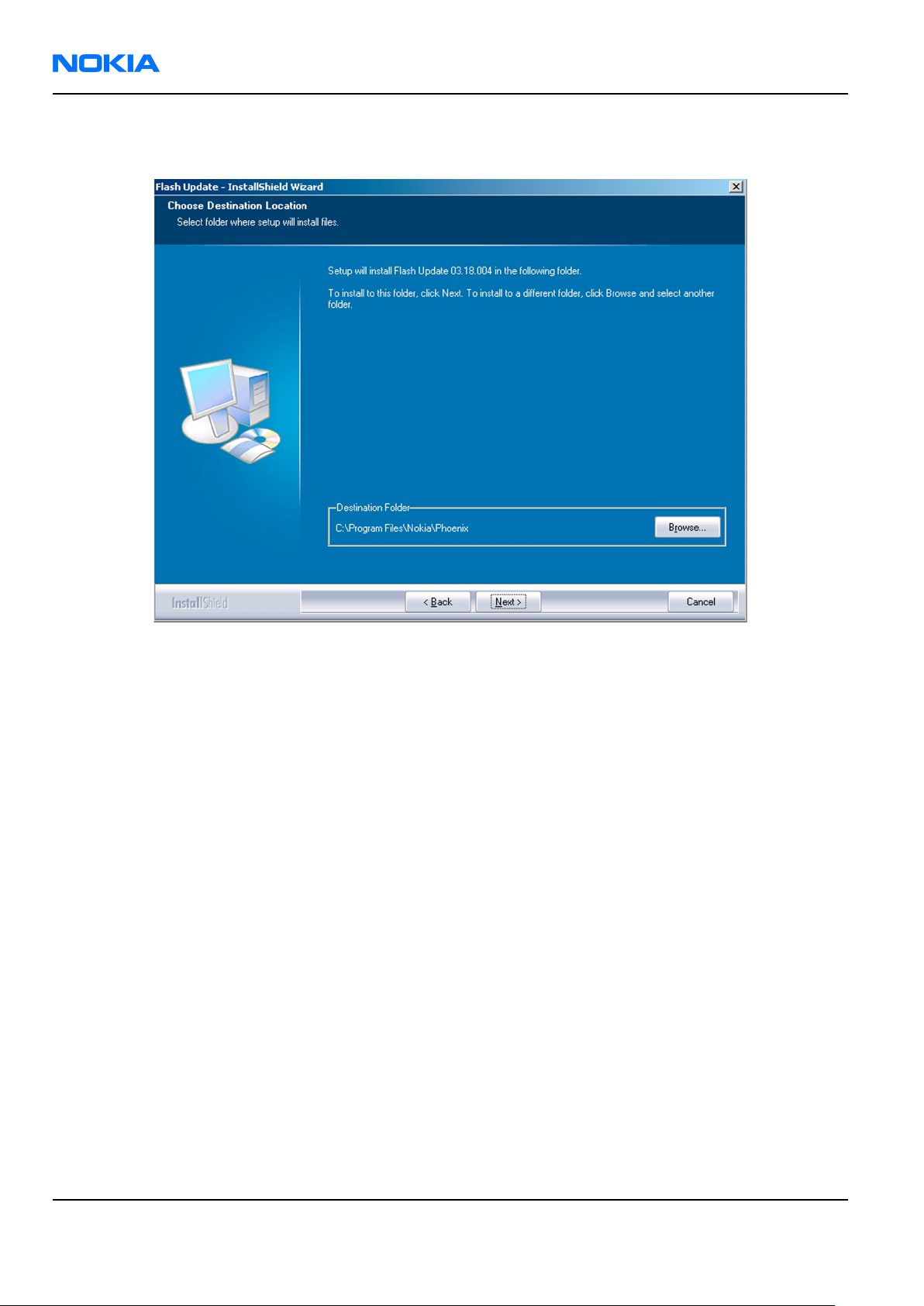
RM-89
Nokia Customer Care Service Software Instructions
3. It is recommended to install the files to the default destination folder
To continue, click Next.
C:\Program Files\Nokia\Phoenix
.
Figure 22 Flash destination folder
When installing the flash update files for the first time, you may choose another location by selecting
Browse (not recommended).
Page 3 –20 COMPANY CONFIDENTIAL Issue 1
Copyright © 2006 Nokia. All rights reserved.
Page 83

RM-89
Service Software Instructions Nokia Customer Care
4. To complete the installation procedure, click Finish .
Figure 23 Finish flash update
Next actions
FPS-10 flash prommer must be updated using
Updating FPS-10 flash prommer software
Phoenix
.
Steps
1. Start
2. Choose the correct connection for your flash prommer: File→Manage Connections...
3. Choose Flashing→Prommer maintenance .
4. To update the FPS-10 software, click Update, and select the appropriate file or
Phoenix
from
C:\Program Files\Nokia\Phoenix\Flash
service software, and log in.
fpsxupd.ini
.
(for FPS-10)
Figure 24 Flash directory window
Issue 1 COMPANY CONFIDENTIAL Page 3 –21
Copyright © 2006 Nokia. All rights reserved.
Page 84
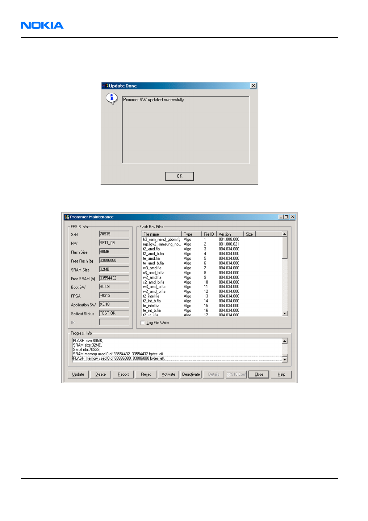
RM-89
Nokia Customer Care Service Software Instructions
Tip: All files can be loaded separately to the prommer used. To do this, click the right mouse button
in the
Flash Box Files
pane and select the file type(s) to be loaded.
5. Click OK.
Figure 25 Prommer software update finished
6. To close the
Prommer Maintenance
window, click Close.
Figure 26
Prommer Maintenance
window
Page 3 –22 COMPANY CONFIDENTIAL Issue 1
Copyright © 2006 Nokia. All rights reserved.
Page 85

Nokia Customer Care
4 — Service Tools and Service
Concepts
Issue 1 COMPANY CONFIDENTIAL Page 4 –1
Copyright © 2006 Nokia. All rights reserved.
Page 86

RM-89
Nokia Customer Care Service Tools and Service Concepts
(This page left intentionally blank.)
Page 4 –2 COMPANY CONFIDENTIAL Issue 1
Copyright © 2006 Nokia. All rights reserved.
Page 87

RM-89
Service Tools and Service Concepts Nokia Customer Care
Table of Contents
Service tools............................................................................................................................................................4–5
AC-33...................................................................................................................................................................4–5
CA-31D................................................................................................................................................................4–5
CA-56RS...............................................................................................................................................................4–5
CU-4.....................................................................................................................................................................4–6
FLS-5....................................................................................................................................................................4–7
FPS-10.................................................................................................................................................................4–7
FS-5.....................................................................................................................................................................4–7
JXS-1....................................................................................................................................................................4–8
MJ-67...................................................................................................................................................................4–8
RJ-86...................................................................................................................................................................4–8
SA-82...................................................................................................................................................................4–9
SB-7.....................................................................................................................................................................4–9
SRT-6.................................................................................................................................................................4–10
SS-46.................................................................................................................................................................4–10
SS-62.................................................................................................................................................................4–10
SS-76.................................................................................................................................................................4–10
Service concepts...................................................................................................................................................4–11
Flash concept with FPS-10..............................................................................................................................4–11
MJ-67 module jig concept...............................................................................................................................4–12
POS (Point of Sale) flash concept...................................................................................................................4–13
Service concept for RF testing and RF/BB tuning.........................................................................................4–14
CU-4 flash concept with FPS-10......................................................................................................................4–15
RF testing and BB testing/tuning..................................................................................................................4–16
List of Tables
Table 8 Attenuation table for antenna coupler SA-82........................................................................................4–9
List of Figures
Figure 27 Basic flash concept with FPS-10.........................................................................................................4–11
Figure 28 MJ-67 module jig service concept......................................................................................................4–12
Figure 29 POS flash concept................................................................................................................................4–13
Figure 30 Service concept for RF testing and RF/BB tuning.............................................................................4–14
Figure 31 CU-4 flash concept with FPS-10..........................................................................................................4–15
Figure 32 RF testing concept and BB testing/tuning........................................................................................4–16
Issue 1 COMPANY CONFIDENTIAL Page 4 –3
Copyright © 2006 Nokia. All rights reserved.
Page 88

RM-89
Nokia Customer Care Service Tools and Service Concepts
(This page left intentionally blank.)
Page 4 –4 COMPANY CONFIDENTIAL Issue 1
Copyright © 2006 Nokia. All rights reserved.
Page 89

RM-89
Service Tools and Service Concepts Nokia Customer Care
Service tools
The table below gives a short overview of service tools that can be used for testing, error analysis and repair
of product RM-89, refer to various concepts.
AC-33 Power supply Universal power supply for FPS-10; included in the FPS-10 sales
package.
CA-31D USB cable The CA-31D USB cable is used to connect FPS-10 or FPS-11 to a PC. It is
included in the FPS-10 and FPS-11 sales packages.
CA-56RS RF cable Small RF cable that is used for RF tuning with MJ-67 module jig.
Issue 1 COMPANY CONFIDENTIAL Page 4 –5
Copyright © 2006 Nokia. All rights reserved.
Page 90

RM-89
Nokia Customer Care Service Tools and Service Concepts
CU-4 Control unit CU-4 is a general service tool used with a module jig and/or a flash
adapter. It requires an external 12 V power supply.
The unit has the following features:
• software controlled via USB
• EM calibration function
• Forwards FBUS/Flashbus traffic to/from terminal
• Forwards USB traffic to/from terminal
• software controlled BSI values
• regulated VBATT voltage
• 2 x USB2.0 connector (Hub)
• FBUS and USB connections supported
When using CU-4, note the special order of connecting cables and
other service equipment:
Instructions
1 Connect a service tool (jig, flash adapter) to CU-4.
2 Connect CU-4 to your PC with a USB cable.
3 Connect supply voltage (12 V)
4 Connect an FBUS cable (if necessary).
5 Start Phoenix service software.
Note: Phoenix enables CU-4 regulators via USB when it is
started.
Reconnecting the power supply requires a Phoenix restart.
Page 4 –6 COMPANY CONFIDENTIAL Issue 1
Copyright © 2006 Nokia. All rights reserved.
Page 91
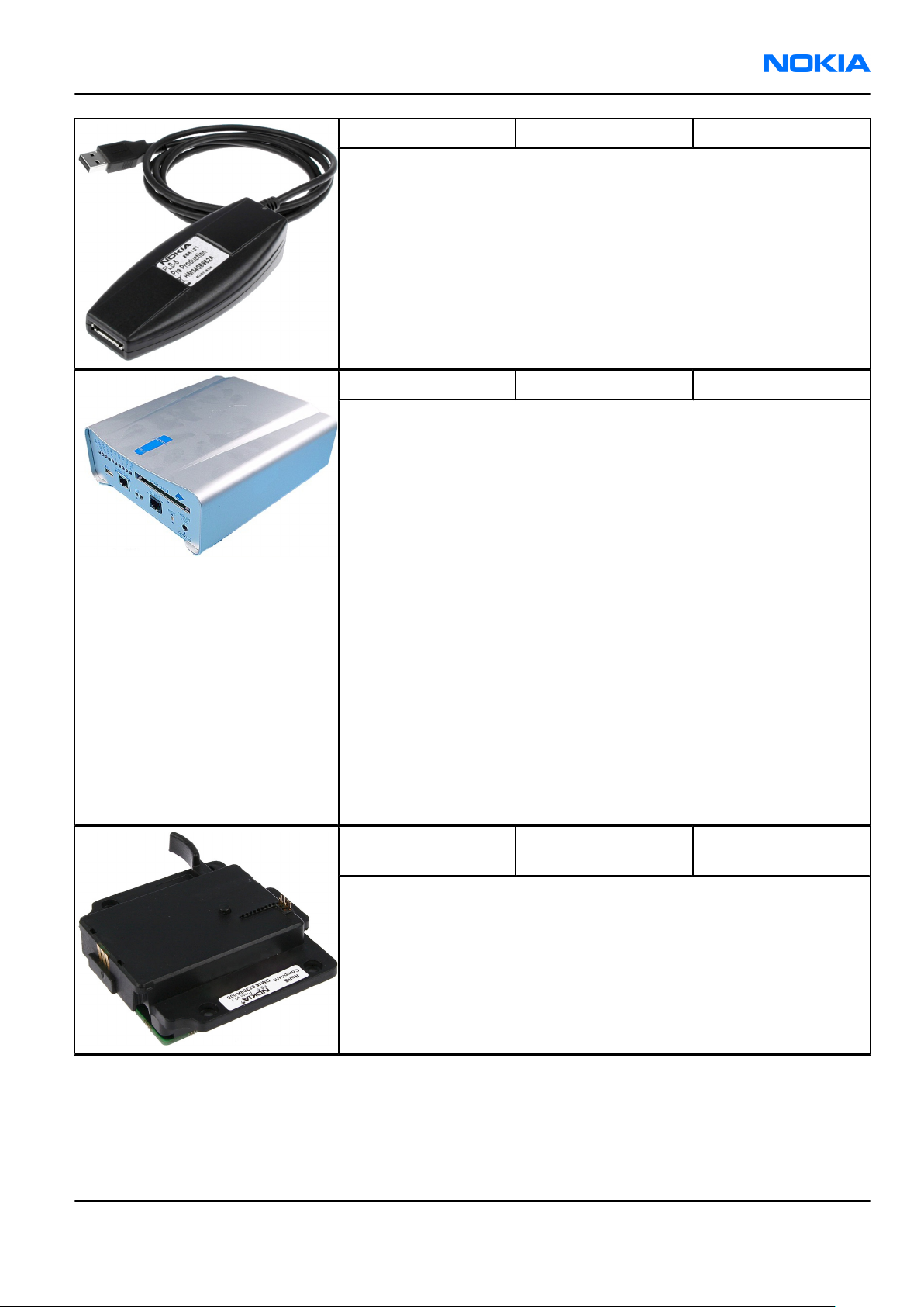
RM-89
Service Tools and Service Concepts Nokia Customer Care
FLS-5 Flash device FLS-5 is a dongle and flash device incorporated into one package,
developed specifically for POS use.
FPS-10 Flash prommer FPS-10 interfaces with:
• PC
• Control unit
• Flash adapter
• Smart card
FPS-10 flash prommer features:
• Flash functionality for BB5 and DCT-4 terminals
• Smart Card reader for SX-2 or SX-4
• USB traffic forwarding
• USB to FBUS/Flashbus conversion
• LAN to FBUS/Flashbus and USB conversion
• Vusb output switchable by PC command
FPS-10 sales package includes:
• FPS-10 prommer
• Power Supply with 5 country specific cords
• USB cable
FS-5 Product specific
adapter
RM-89 specific adapter.
Issue 1 COMPANY CONFIDENTIAL Page 4 –7
Copyright © 2006 Nokia. All rights reserved.
Page 92

RM-89
Nokia Customer Care Service Tools and Service Concepts
JXS-1 RF shield box Because the WCDMA network disturbs the RX side testing of the WCDMA
phone and the Tx signal of the WCDMA phone can severely disturb the
WCDMA network, a shield box is needed in all testing, tuning and fault
finding which requires WCDMA RF signal.
The shield box is not an active device, it contains only passive filtering
components for RF attenuation.
MJ-67 Module jig RM-89 specific module jig.
•
Attenuation values for galvanic RF connection
Module Jig
Band Tunin
Chann
el
GSM
850 190 0
GSM
900 37 0
GSM
1800 700 -0.2
GSM
1900 661 0
9750/
WCDMA
2100
WCDMA
1900
WLAN
RJ-86 Soldering jig
1070
Atten
g
0 -0.5
uatio
n RX
Tolera
nce RX
+/-
0.1 -0.1
+/-
0.1 -0.1
+/-
0.1 -0.9
+/-
0.1 -0.6
+/-
0.1 -0.5
Attenu
ation
TX
Toler
ance
TX
+/-
0.1
+/-
0.1
+/-
0.1
+/-
0.1
+/-
0.1
RM-89 specific soldering jig.
Page 4 –8 COMPANY CONFIDENTIAL Issue 1
Copyright © 2006 Nokia. All rights reserved.
Page 93

RM-89
Service Tools and Service Concepts Nokia Customer Care
SA-82 GSM&WCDMA coupler RM-89 specific GSM&WCDMA coupler.
• Flash adapter antenna coupler SA-82 attenuation table for NOKIA
E61, measured with Universal Radio Communication Tester
CMU-200.
Table 8 Attenuation table for antenna coupler SA-82
System Channel Tx-att. (dB) Rx-att. (dB)
GSM 850 128 3.5 4
190 4 4
251 4.3 4
GSM 900 975 3.7 3
38 3.5 3
124 4 3
GSM 1800 512 7 5
698 5.8 5
885 5.4 6
GSM 1900 512 5.7 5
700 5.3 5
810 5.5 7
TX / RX
WCDMA 9612 / 10562 10.6 10
9750 / 10700 10.5 11
9888 / 10838 8.6 11
Note: Tx-attenuation tolerance is +/-0.5 dB.
Rx-attenuation tolerance is +/-1.0dB.
SB-7 WLAN test box WLAN test requires defined position for the device.
Issue 1 COMPANY CONFIDENTIAL Page 4 –9
Copyright © 2006 Nokia. All rights reserved.
Page 94

RM-89
Nokia Customer Care Service Tools and Service Concepts
SRT-6 Opening tool SRT-6 is used to open phone covers and B-to-B connectors.
SS-46 Interface adapter SS-46 acts as an interface adapter between the flash adapter and
FPS-10.
SS-62 Generic flash adapter
base for BB5
• generic base for flash adapters and couplers
• SS-62 equipped with a clip interlock system
• provides standardised interface towards Control Unit
• provides RF connection using galvanic connector or coupler
• multiplexing between USB and FBUS media, controlled by VUSB
SS-76 Domesheet assembly
jig
Page 4 –10 COMPANY CONFIDENTIAL Issue 1
Copyright © 2006 Nokia. All rights reserved.
Page 95
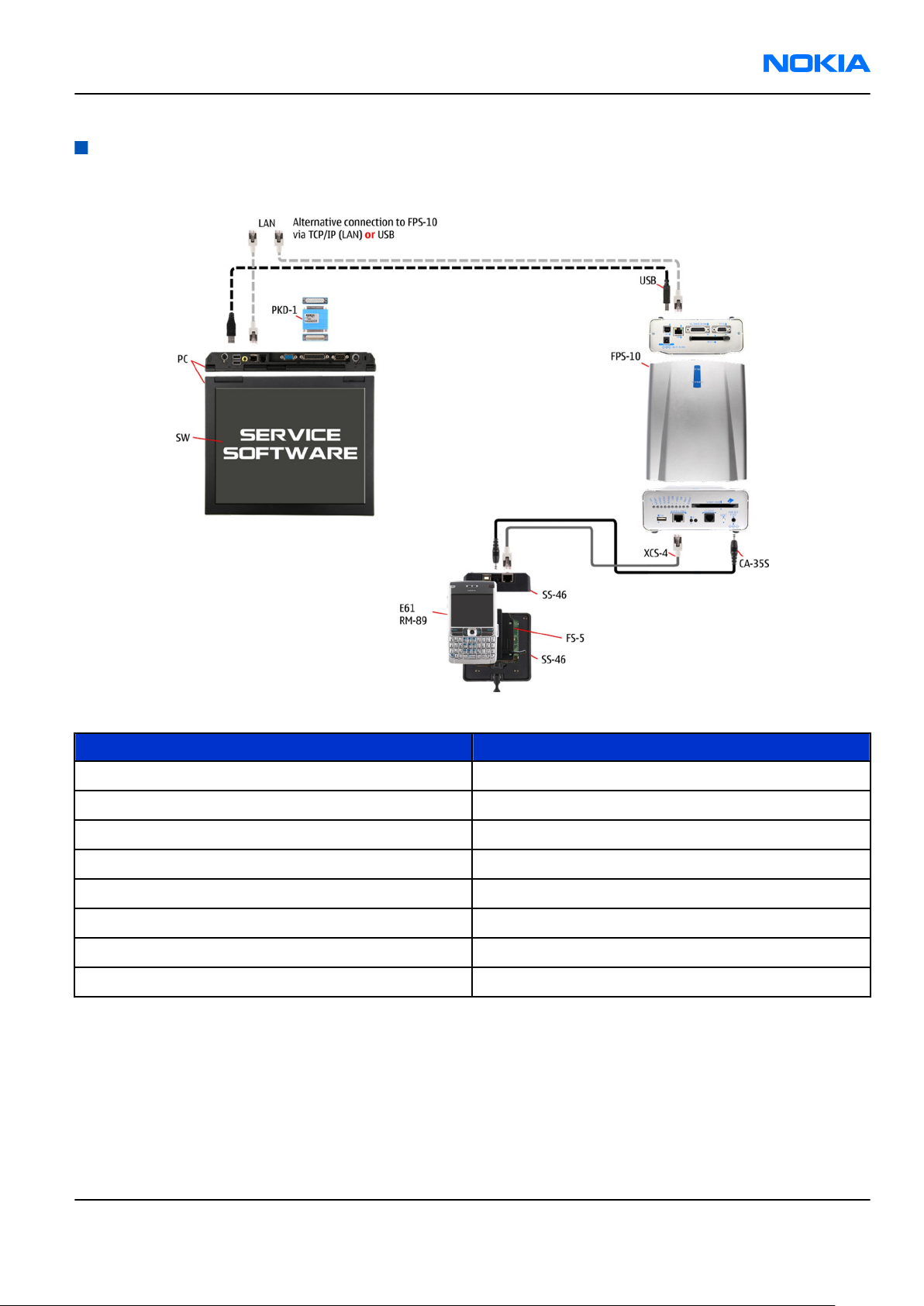
RM-89
Service Tools and Service Concepts Nokia Customer Care
Service concepts
Flash concept with FPS-10
Figure 27 Basic flash concept with FPS-10
Description Type
FS-5 Flash adapter
SS-46 Interface adapter
CA-35S Power cable
XCS-4 Modular cable
Standard USB cable
FPS-10 Flash prommer box
Standard USB cable
PKD-1 SW security device
Issue 1 COMPANY CONFIDENTIAL Page 4 –11
Copyright © 2006 Nokia. All rights reserved.
Page 96

RM-89
Nokia Customer Care Service Tools and Service Concepts
MJ-67 module jig concept
Figure 28 MJ-67 module jig service concept
Type Description
MJ-67 Module jig
CU-4 Control unit
FPS-10 Flash prommer box
SX-4 Smart card
XCS-4 Modular cable
PCS-1 DC power cable
Standard USB cable
Standard USB cable
GPIB control cable
XRS-6 RF cable
PKD-1 SW security device
RF shield box
Page 4 –12 COMPANY CONFIDENTIAL Issue 1
Copyright © 2006 Nokia. All rights reserved.
Page 97

RM-89
Service Tools and Service Concepts Nokia Customer Care
POS (Point of Sale) flash concept
Figure 29 POS flash concept
Type Description
CA-53 USB connectivity cable
FLS-5 POS flash device
ACP-8 Power adapter
Issue 1 COMPANY CONFIDENTIAL Page 4 –13
Copyright © 2006 Nokia. All rights reserved.
Page 98

RM-89
Nokia Customer Care Service Tools and Service Concepts
Service concept for RF testing and RF/BB tuning
Figure 30 Service concept for RF testing and RF/BB tuning
Description Type
MJ-67 Module jig
CU-4 Control unit
Standard USB cable
PCS-1 DC power cable
Standard USB cable + smart card reader
SX-4 Smart card
XRS-6 RF cable
GPIB control cable
PKD-1 SW security device
RF shield box
Page 4 –14 COMPANY CONFIDENTIAL Issue 1
Copyright © 2006 Nokia. All rights reserved.
Page 99
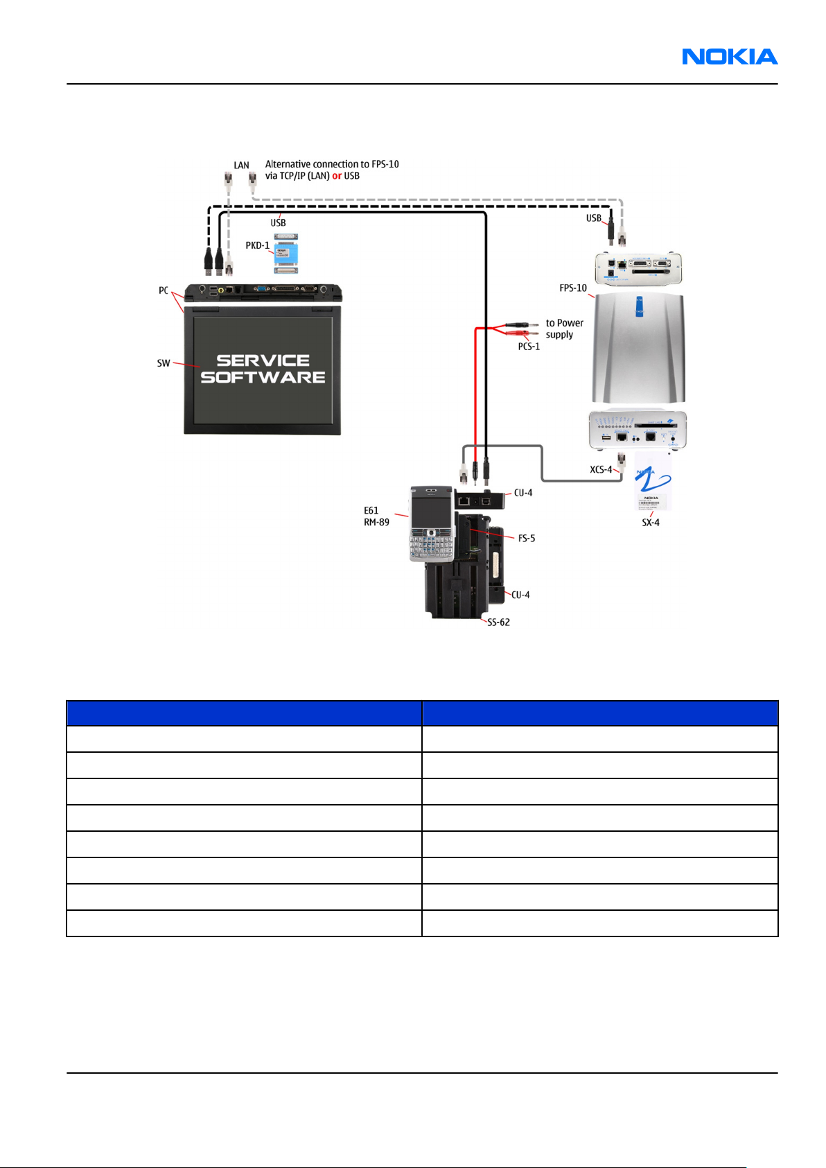
RM-89
Service Tools and Service Concepts Nokia Customer Care
CU-4 flash concept with FPS-10
Figure 31 CU-4 flash concept with FPS-10
Note: FPS-8 concept can also be used for flashing.
Description Type
SS-62/FS-5 Flash adapter
CU-4 Control unit
XCS-4 Modular cable
PCS-1 Power cable
FPS-10 Flash prommer box
Standard USB cable
Standard USB cable
PKD-1 SW security device
Issue 1 COMPANY CONFIDENTIAL Page 4 –15
Copyright © 2006 Nokia. All rights reserved.
Page 100
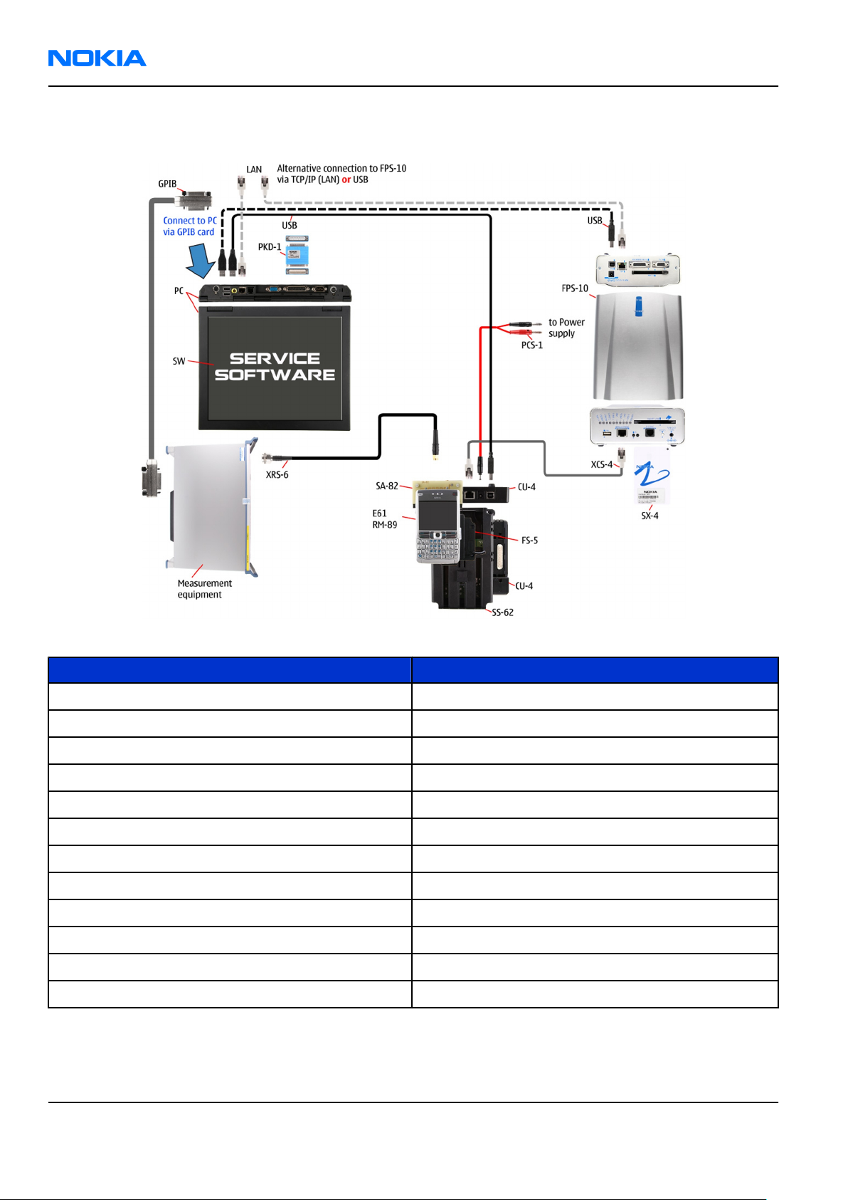
RM-89
Nokia Customer Care Service Tools and Service Concepts
RF testing and BB testing/tuning
Figure 32 RF testing concept and BB testing/tuning
Type Description
SS-62/FS-5 Flash adapter
CU-4 Control unit
SA-82 RF coupler
PCS-1 Power cable
XCS-4 Modular cable
Standard USB cable
Standard USB cable + smart card reader
SX-4 Smart card
GPIB control cable
XRS-6 RF cable
PKD-1 SW security device
RF shield box
Page 4 –16 COMPANY CONFIDENTIAL Issue 1
Copyright © 2006 Nokia. All rights reserved.
 Loading...